Download User Manual - INSTRAS SCIENTIFIC
Transcript
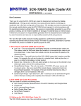
SCK200 | SCK200P Spin Coater Kit USER MANUAL v1.1 05/07/2013 Dear Customers: Thank you for using the SCK200 | SCK200P spin coater kit designed and produced by Instras Scientific LLC. Wrong use and operation may cause personal injuries and damage to equipment due to the fast moving parts of the product. We strongly recommend customers read this manual carefully before using the kit and operate it in strict accordance with the operating procedure outlined below. We assume no responsibility generated by use of this product, including, but not limited to liabilities for damage of incidental losses or indirect losses. Furthermore, we assume no responsibilities generated from the disassembly and/or modification by users themselves and assume no responsibility caused by third party products. We have the right to alter products including appearance, performance parameters, and operating requirements without advance notice. We make no guarantee, declaration or promise on whether the product is suitable for specific purposes of users. I. Main Features of the SCK200 | SCK200PSpin Coater Kit ● Low Cost The cost of this kit is significantly less than a commercial spin coater unit. This makes it ideal for R&D work where the benefits of a commercial spin coater is yet to be determined. It also means that multiple units can be purchased to speed up the research process. ● Compact Size The small foot print of the SCK200 | SCK200P allows the unit to easily fit in a crowded hood, inside a glove box, or even in an Aldrich’s AtmosBag or similar product. ● Easy to Use and Setup Simply turn on the unit, place sample on chuck, put on the chamber cover, select spin speed, and start the coating process. Moreover, the kit only needs a 110V or 220V A/C power source. No vacuum pump is required. ● Digital Control By using an offtheshelf controller, combined with our custom firmware, speed can be repeatedly controlled accurately (within +/ 200 rpm, or +/ 20 rpm for SCK200P). Basic Ramp functionality is also now available. ● Dynamic Spin Range Spin rates from 500 6,000 rpm (400 9,000 rpm for SCK200P) can be achieved with good control. Most spin coating work is typically done between 1,200 and 5,000 rpm. II. SCK200 | SCK200P Spin Coater Kit Contents The spin coater kit contains the following items: 1. Spin Coating Chamber (Motor/Aluminum Chuck/CD Cakebox) and Plexiglas Base 2. Digital Control Unit 3. 9V or 12V DC Universal Power Supply 4. Roll of Double Sided Tape 5. Set of Plastic Tweezers 6. User Manual 7. Laser Tachometer (SCK200P only and while supplies last) III. Setting up the SCK200 | SCK200P Spin Coater Kit The kit requires only a two connections to setup. (1) The power supply input, (2) connection to the motor/chuck. The connections to the PDC2 are shown in the diagram below. Once all the connections are made, clamp or weigh down the Spin Chamber to prevent it from moving during the spin coating process. Also, it is strongly recommend that the unit be placed in a fume hood, or glove box to prevent the escape of any dangerous vapors generated during the spin coating process. IV. Using the SCK200 | SCK200P Spin Coater Kit Warning: NEVER START THE MOTOR/CHUCK WITHOUT THE SPIN CHAMBER COVER IN PLACE Before powering on the unit, make sure the “Speed Control Knob” is at the lowest position. When the unit is powered on, there is a short musical chime, a two (2) second pause followed by one final beep. This indicates the unit is ready for use. If the musical chime is followed by a continuous series of beeps, it means the connections to the PDC2 are not correct or there is something wrong with the PDC2. If there is no chime, or beeps, the motor is likely not connected. By default the unit is placed into “Analog Control” mode, and is paused. Pause is indicated by a series of beeps coming from motor, and the word “PAUSE” flashing on LCD display. To unpause the unit, simply pressed the ENTER key once. Basic Spin Coating: 1. Place substrate in the center of the chuck using the double sided tape provided. Only about ½” piece of tape is all that is necessary, but that depends on the size and weight of substrate. Bigger/heavier substrates will require more tape. This tape does not need to be changed every time the substrate is changed, and can be reused as long as it holds the substrate in place. 2. Once sample is firmly in place, then there are two ways to proceed. 1) Place the desired solution on the substrate , then use the speed control knob to get a speed close to the desired value. The unit should be able to attain a stable speed within +/ 200 rpm (+/ 20 rpm for SCK200P) of the set value (this accuracy will be fine for most spin coating work). 2) Use the speed control knob to achieve the desired speed, then drop the desired solution onto the substrate. Which method works best will depend on the particular application. 3. Depending on what is being coated, the film/substrate should be left spinning from anywhere between 20 to 60 seconds. The amount of spinning time depends primarily on drying time of the coating solution. 4. Once the film is dry, press the “EXIT” key to bring the chuck to a stop and enter PAUSE mode. The current speed setting will remain the same (provided the control knob is not turned) until the unit is powered off. Please note that there maybe a sudden, brief acceleration of chuck when the “EXIT” is pressed, but chuck should stop rotating shortly thereafter. WAIT FOR CHUCK TO STOP SPINNING BEFORE REMOVING SPIN CHAMBER COVER AND SUBSTRATE. It is now safe to remove the coated substrate at this time. 5. Use a flat/wide tweezer to remove substrate by slowly creating a gap between the adhesive tape and bottom of the substrate. Advance Spin Coating: With the PDC2, users are now able to better control the spin coating process by using the “Digital” and “Ramp“ modes. Digital Control Mode In this mode the the UP and DOWN keys are used to change and set the speed, rather than the control knob. To access this mode, from the Analog Control: 1. Press the EXIT key twice to go to the main menu [photo here]. 2. Using the DOWN key, select “Digital Control” and press ENTER. For safety, the motor is paused, and is indicated by the blinking word “PAUSE”, and the continuous beeping. 3. Press the ENTER to exit pause, then use the UP and DOWN keys to change the speed. Repeatedly pressing ENTER again will allow the PWM increment to be changed between 1, 2, 4, 10, 100 us. 4. To pause, press the EXIT key once. Pressing the EXIT key a second time will return to the main menu. Ramp Mode In this mode, preconfigured programs, which have two speed steps (MIN and MAX), are used to allow the coating solution to be first evenly spread at a lower speed, before being thinned at a higher speed. The minimum and maximum speeds, along with their respective dwell times (in seconds) are configured through the SETUP menu (see section V below). There are three of these programs. To access this mode, from the Analog Control: 1. Press the EXIT key twice to go to the main menu [photo here]. 2. Using the DOWN key, select “Ramp” and press ENTER (see image). For safety, the motor is paused, and is indicated by the blinking word “PAUSE”, and the continuous beeping. 3. USING either the UP or DOWN key, select one of the three ramp programs to run. 4. Once a program is selected, press ENTER to start program. At this point the motor speed will be set to the minimum values and MIN text will blink inversely with the countdown of the seconds remaining for that step. Once the MIN step has completed, the MAX step is automatically selected. The MAX text will now intermittently blink with the countdown, and motor speed will be increase to the predefined setting. 5. After the MIN and MAX steps have both completed, the motor will again be paused. The substrate can be removed safely once the chuck has stopped moving. V. Configuring the PDC2 The PDC2 controller has a number of functions that can be configured by the user, by selecting “Setup” from the main menu. The UP and DOWN keys are used to select the function to configure. The following functions can be configured (see Figure): ● SET P# This is used to specified the pair of magnets in the motor in order to get accurate RPM measurements. It can be changed by repeatedly pressing the ENTER key; however, users should not have to modify this value from the default value of 7. ● START Specifies the default control mode the unit enters when powered on. Choices are None, Analog, Digital, and Ramp. To change, repeatedly press the ENTER key until the desired mode is displayed, then press the EXIT key to save. ● BL This option is used to turn the LCD backlight On and Off. The change, press the ENTER key, then press the EXIT to save. ● RAMP Used to configure the MIN/MAX speeds and corresponding dwell times (in seconds) for the three Ramp programs. To configure those program: ○ Use the UP and DOWN keys to select Ramp program 1, 2, or 3. ○ Press the ENTER key to set the MIN speed value for the selected program. The Control knob is used change the speed. The motor will spin at this point in order to measure the RPM. ○ Press the ENTER key now to modify the dwell time at the MIN speed. Use the UP and DOWN keys to set the dwell time in seconds. ○ Press the ENTER key now to set the MAX speed value. Again, use the Control knob to change the speed and measure the RPM. ○ Press the ENTER to set key now to modify the dwell time at the MAX speed. All parameters for the Ramp program are now set and saved. If mistake was made, then pressing ENTER at this point will allow all the parameters for the Ramp program to be configured again. ○ Press EXIT to select another Ramp program, or Press EXIT again to return to Main menu. VI. Caring for your Spin Coater Kit Caring for the spin coater kit primarily involves keeping the spin chamber and the aluminum chuck clean. If the spin chamber becomes too dirty, or damaged, it can be easily replaced with a new one. Given the spin chamber is just an empty CD cakebox, there are probable one lying around which can be used. Mounting and clearance holes will need to be drilled in the correct location though. A 5/64 hex key will be need to remove the chuck, before the CD cakebox can be replaced. A predrilled spin chamber can also be purchased by contacting our Customer Service Department at [email protected]. VII. Limitations Though fully functional as a spin coater, the SCK200 | SCK200P does have a few limitations. Firstly, for best performance, substrate size should be less than 2 sq. inches, since they are held onto the chuck by double sided adhesive tape (this has proven effective at holding glass slides (3/8” x 1”) in place, up to 10,000 rpm). Bigger/heavier substrates can be used, but performance might not be optimal and would require additional mounting tape. Also, due to the electronic controller/motor employed, the ability to optimize the spinning process (i.e. set the ramp and final spin speed with a high degree of control) is limited. Typically, the unit can be set within +/ 200 rpm (+/ 20 rpm for SCK200P) of the desired speed. For example, if you want a spin speed of 3000 rpm, then you will be able to get the unit to sit stable somewhere between 2800 and 3200 rpm, using the K1 RPM meter as a guide. For all practical purposes, any speed within that range will result in films with the same/similar relevant properties. In short, based on your particular R&D application, this unit can be all you need, and if it is not, then a commercial spin coater can be purchased at little financial loss. VIII. Handling Common Problems Problem Solution(s) Spin Coater does not turn on 1. Make sure A/C adapter is plugged into the back of the controller unit and into the wall outlet. 2. Flip the power switch on. In the on position, the LCD display of the PDC2 is illuminated. 3. If the above steps does not work send email to [email protected]. PDC2’s LCD screen goes blank Due to electronic noise, the LCD of the PDC2 could occasionally go blank or get corrupted. Turning the power switch ON and OFF will fix this issue. The ON OFF switch on the PDC2 doesn’t seem to do anything The ON OFF switch on the PDC2 is not used when connected to the SCK Interface Module. Instead, the inline switch on the interface module is used to control power to the spincoater components. Controller unit is on, but chuck will not spin when the control knob (in Analog control), or UP and DOWN keys are pressed (in Digital control). 1. Make sure the motor is plugged in. 2. Make sure system is not paused. The system beeps continuously when paused. Sample keeps flying off chuck when spinning Replace double sided tape on chuck or use more tape. The RPM values fluctuates by +/ 60 rpm, how do I know what the real speed of the chuck is? The resolution of the RPM counter is +/ 60 rpm, so this is normal. The real speed of the chuck is going to be within this range. A noncontact laser tachometer can always be used to verify speed. IX. Warranty See website (http://stores.ebay.com/instrasscientific) for warranty information


