1
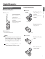
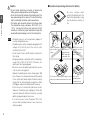
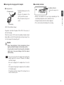
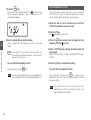
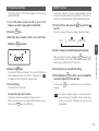
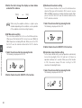
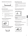
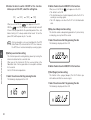
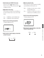
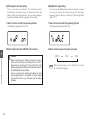
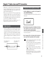
WIDE BAND COMMUNICATION RECEIVER
DJ-X7T/E
Instruction Manual
PRI
MW
TONE
BANK
V/P/M
SCAN
BAND
SHIFT
PWR
10M/1M
DJ-X7
WIDE BAND
COMMUNICATION RECEIVER
ALINCO, INC.
NOTICE / Compliance Information Statement
This device has been tested and found to comply with the limits for a Class B digital device, pursuant to part 15 of the FCC Rules.
These limits are designed to provide reasonable protection against harmful interference in a residential installation.
This device generates, uses, and can radiate radio frequency energy and, if not installed and used in accordance with the instruction
manual, may cause harmful interference to radio communications. However, there is no guarantee that interference will not occur in a
particular installation. If this device does cause harmful interference to radio or television reception, which can be determined by turning the
device off and on, the user is encouraged to try to correct the interference by one or more of the following measures:
• Reorient or relocate the receiving antenna.
• Increase the separation between the equipment and receiver.
• Connect the equipment to an outlet on a circuit different from that to which the receiver is connected.
• Consult the dealer or an experienced radio/TV technician for help.
Tested to Comply
With FCC Standards
FOR HOME OR OFFICE USE
Information in this document is subject to change without notice or obligation. All brand names and trademarks are the property of their
respective owners. Alinco cannot be liable for pictorial or typographical inaccuracies. Some parts, options, and/or accessories are
unavailable in certain areas. Changes or modifications not expressly approved by the party responsible for compliance could void the user's
authority to operate the device.
Wide Band Communication Receiver DJ-X7T
This device complies with part 15 of the FCC Rules. Operation is subject to the following two conditions: (1) This device may not cause
harmful interference, and (2) this device must accept any interference received, including interference that may cause undesired operation.
Conformity Information
In case the device you have purchased is marked with a CE symbol, a copy of the relative conformity certificate or document can be
reviewed at http://www.alinco.com/usa.html. This device is authorized for use in all EU and EFTA member states.
MANUFACTURER: ALINCO, INC. Shin Dai Building 9F, 1-2-6, Dojimahama, Kita-ku, Osaka, 530-0004, Japan
2
Copyright © 2005 All rights reserved. No part of this document may be reproduced, copied, translated, or transcribed in any form or by any
means without the prior written permission of Alinco, Inc., Osaka, Japan.
English Edition Printed in Japan.
Table of Contents
Precautionary Statement ..........................................................5
Precautionary Statement - External Power Supply...................5
Request and Agreement ..........................................................5
■Memory types ............................................................19
■Programming to memory channel .............................20
■Clearing memory channel .........................................21
■Programmable items to memory channels................21
Chapter 1 Features ..........................................................6
Chapter 5 Advanced Operations ..................................22
1.1 Standard Accessory List ....................................................6
5.1 Scanning Function............................................................22
■VFO scan ...................................................................22
■Programmed scan .....................................................23
■Preset scan................................................................23
■Memory scan .............................................................23
5.2 Memory Skip Function......................................................24
5.3 Key-lock Function.............................................................25
5.4 Priority Monitoring Function..............................................25
5.5 Descrambling Function ....................................................25
5.6 Tone Squelch Function.....................................................26
5.7 Tone Scan Function..........................................................27
5.8 Shift Function....................................................................27
Precautions ......................................................................5
Chapter 2 Accessories ....................................................7
2.1 Mounting Arrangement.......................................................7
■Installing & uninstalling antenna..................................7
■Installing & uninstalling battery ...................................7
■Precaution for preventing short-circuit of battery ........8
■Receiving while charging with AC adapter .................9
■Low battery indicator ...................................................9
Chapter 3 Names and Functions of Parts ....................10
3.1 External View ....................................................................10
■Top/Front panel .........................................................10
■Side panel .................................................................11
3.2 Key Operations.................................................................12
3.3 Icons and Indicators.........................................................13
Chapter 4 Basic Operations ..........................................14
4.1 Turning Power ON ............................................................14
4.2 Adjusting Volume Level....................................................14
4.3 Adjusting Squelch Level...................................................15
■Monitor function .........................................................15
■Mute function .............................................................16
4.4 Operating Modes .............................................................16
■Switching among modes ...........................................16
4.5 Frequency Settings ..........................................................17
■VFO mode .................................................................17
■Preset mode ..............................................................18
■Memory mode ...........................................................19
4.6 Memory Mode ..................................................................19
Chapter 6 Set Mode Configurations .............................28
6.1 Set Mode Menu List..........................................................28
6.2 Configuring Values/Parameters of Menu Items................28
6.3 Set Mode Configurations..................................................29
(1)Attenuator function setting.......................................29
(2)Antenna Type Switching setting ..............................29
(3)AM Bar-antenna setting ...........................................30
(4)Shortwave Bar-antenna setting................................30
(5)Illumination Lamp function setting ...........................30
(6)Scan Type Switching setting ...................................31
(7)Priority Monitoring function setting ..........................31
(8)Auto-Power-Off function setting...............................31
(9)Battery-save function setting ...................................32
(10)Key-touch Beep function setting ...........................32
(11)Bell (Pager) function setting ..................................32
(12)Monitor/Mute function setting ................................33
(13)Monitor-key Operation setting ...............................33
3
(14)Write-protect function setting.................................34
(15)Modulation Type setting ........................................34
Chapter 7 Cable-clone and PC Connection .................35
7.1 Cable Connection.............................................................35
7.2 Operation for Receiving Data (on the Slave)....................35
7.3 Operation for Transferring Data (on the Master) ..............36
Chapter 8 Maintenance and Reference........................37
8.1 Troubleshooting................................................................37
8.2 Resetting ..........................................................................38
■Factory default value .................................................38
8.3 Optional Accessory List ...................................................38
8.4 Table of Available CTCSS Tones .....................................39
Chapter 9 Specifications ...............................................40
This manual uses the following icons to explain:
Caution
Items indicated with this icon mention precautions for use
and procedures which need to be followed. Otherwise,
person may be injured, or the receiver including
accessories may be damaged or not operate properly.
4
NOTE
Items indicated with this icon mention precautions for
use and procedures which need to be followed.
Memo
Items indicated with this icon mention supplementary
and referential information.
Precautions
Precautionary Statement
• Do not open the case nor touch the interior components.
Tampering can damage the receiver.
• Do not place the receiver in any place where it will be
subjected to direct sunlight, dust, or high temperatures.
• Keep the receiver away from TVs, tuners, or other equipment
if it interferes with reception.
• Ensure that the provided antenna is securely mounted.
• Turn the power OFF immediately if the receiver should emit
smoke or strange odors. Ensure that the receiver is safe, then
contact the nearest Alinco Service Center.
Precautionary Statement - External Power Supply
• Use a regulated 3.7V to 6.0V DC external power supply.
• Never use any external power supply which exceeds 6.5V.
Otherwise, this may cause the serious damage.
• To charge the battery or operate the receiver using AC power,
use the provided AC adapter (EDC-126 or EDC-128
depending on the version). Connect the adapter to the
receiver's DC-IN jack directly.
• When power is supplied from the cigarette socket of a car,
use the optionally available cigar-socket DC cable (EDH-32).
• Turn the receiver's power OFF when connecting or
disconnecting the cable of external power supply.
Request and Agreement
• This receiver is manufactured and shipped under strict quality
control. However, in some rare instances, if questionable or
doubtful points are found, please notify the store where you
purchased the receiver.
• Since this is a wide band communication receiver, its internal
oscillation can sometimes block a signal, or detect an internal
signal (sometimes referred to as a "birdie"). These symptoms are
not a malfunction.
• Specifications and information found in this document are
subject to change without notice.
5
Chapter 1 Features
1
Features
• DJ-X7 is a wide band receiver and can be applied to
business use.
• DJ-X7 receives AM radio with the internal bar-antenna.
• DJ-X7 receives high frequency wave (shortwave) with the
internal bar-antenna.
• DJ-X7 receives FM radio with the provided earphone antenna.
• DJ-X7 features the Shift function.
• DJ-X7 features the Tone Squelch function, and it covers 39
CTCSS tones.
• DJ-X7 features the Cable-clone function.
• DJ-X7 features the PC Connection function*.
• DJ-X7 adopts Lithium ion rechargeable battery.
*
6
The free editing software can be downloaded at our website
(http://www.alinco.com). The optional PC interface-cable
(ERW-4C) is required to interface your computer and the
DJ-X7. Please visit our website for more details before you
purchase the ERW-4C as some restrictions may apply
depending on your computer conditions.
1.1 Standard Accessory List
Standard accessories may vary. Please contact your dealer for
details.
• A Li-Ion rechargeable battery pack*
DJ-X7T/E: EBP-58N (3.7V 600mAh)
• An AC adapter for both recharging battery and supplying
power** (6.0V 0.5A)
DJ-X7T: EDC-126 (120V)
DJ-X7E: EDC-128 (220V)
• An SMA whip antenna
DJ-X7T/E: EA-131
• A curl-cable earphone/antenna
DJ-X7T/E: EME-25
• An antenna cap
• An instruction manual
* Hereinafter referred to as battery or battery pack.
** Hereinafter referred to as AC adapter or adapter.
Chapter 2 Accessories
2.1 Mounting Arrangement
■Installing & uninstalling antenna
■Installing & uninstalling battery
1.Hold the antenna at the base.
2.Attach the antenna to the
antenna connector.
3.Turn the antenna clockwise
until it stops.
4.Ensure the antenna is securely
installed to the receiver.
Accessories
1.Align the projections on the
battery with the grooves on
the receiver.
2.Push the battery in the direction
of the arrow.
Projections
●Installing antenna
2
●Installing battery
Grooves
3.Push down the latch of the
battery until it clicks.
●Uninstalling antenna
Turn the antenna counterclockwise.
Caution
When antenna connector conversion is necessary, be sure
to select a proper conversion connector or cable which
does not overburden the receiver. Otherwise, this may
cause the damage to the receiver and/or the antenna.
NOTE
Latch
●Uninstalling battery
1.Push the latch of the battery
upward.
Latch
Installing an excessively high performance external
antenna may get worse of the receiving conditions.
2.Pull out the battery in the
direction of the arrow.
7
Caution
• Do not modify, dismantle, incinerate, or immerse the
battery pack, as these practices can be dangerous.
• Do not short-circuit the terminals of the battery pack. This
may cause damage to the receiver. The short-circuit may
lead to overheating the battery, which causes burns.
• The battery pack should be stored in dry places where
the temperature range is between -20 to 45˚C (-4 to
113˚F). Leaving the battery pack exposed in high
humidity or outside the proper temperature range may
cause battery liquid leakage or rust on the metal portion.
2
Accessories
NOTE
8
• The battery pack is not charged when shipped. It
must be charged before use.
• The battery pack can be charged by plugging the AC
adapter to the DC-IN jack of the receiver after
mounting it to the DJ-X7.
• It takes up to 2 hours and 30 minutes (maximum) to
fully charge.
• Charging should be conducted within a temperature
range of 0 to 40˚C (32 to 104˚F). Otherwise, the
battery won't be charged properly.
• Be sure to remove the battery pack when the receiver
is not in use for a long period.
• Typically, the battery pack can be charged up to 500
times. However, it is considered consumed if the period
of use significantly drops despite the battery being
charged for the aforementioned charging time. When
this happens, replace the old battery with a new one.
• In the interests of environmental protection, do not
dispose of the battery pack improperly. Check with
your local solid waste officials for details on recycling
options or proper disposal in your area.
• It is not necessary to turn the power OFF of the
receiver while charging. However, noise may occur
during reception.
■Precaution for preventing short-circuit of battery
Terminals
DON'T carry with any
type of metals. (e.g.
chains)
Be extra cautious when
carrying the battery pack; the
short-circuit will produce surge
current possibly resulting in
fire.
DON'T put it in bags
whose interior is
plated with metal.
DON'T wrap with a
metal plated cloth.
Put it in a non-conductive plastic bag, or wrap it
with a non-conductive material when you carry.
DON'T place it in the
proximity of metals or
conductors. (e.g.
nails, chains)
Protect it by
spreading a nonconductive sheet.
■Receiving while charging with AC adapter
Low battery indicator
●Charging battery
AC adapter plug
■Low battery indicator
Power plug
Indicates the charge level is
low.
2
• Battery consumption level may change depending on the
surrounding temperature or the conditions of use.
• Charge the battery when the indicator appears.
• This is not an indicator for battery life remaining.
Accessories
1.Install the battery pack to the
receiver.
2.Plug the AC adapter to the
DC-IN jack of the receiver.
3.Plug the power plug to an
outlet.
(EDC-128 has different shape.)
Regardless of whether the power ON or OFF of the receiver, it
will start charging.
When the receiver is OFF state, the low battery indicator shown
below blinks and the RX lamp illuminates during charge. Once
it is fully charged, the lamp will go off.
Caution
• Never charge batteries of other manufacturers. Never
plug the provided AC adapter to other devices, either.
• If you should short-circuit the terminals with metal objects
and the like, it may cause damage to both the receiver
and the battery.
NOTE
• Be sure to connect the AC adapter after mounting the
battery pack to the receiver. Otherwise, the battery
won't be charged.
• Be sure to unplug the AC adapter when it is not in
use.
• The required charging time depends on the condition
of the battery pack.
• The battery won't be charged if the voltage from an
outlet is extremely low.
9
Chapter 3 Names and Functions of Parts
3.1 External View
■Top/Front panel
Item
3
Names and Functions of Parts
1
Earphone jack
2
Dial
3
RX lamp
4
Keypad
5
Speaker
6
Power key
7
LCD
3
1
2
7
PRI
MW
TONE
V/P/M
SCAN
BANK
BAND
4
SHIFT
EAR
PUSH
VOL/SQL
SET
6
PWR
10M/1M
5
DJ-X7
WIDE BAND
COMMUNICATION RECEIVER
10
Description
This is for plugging an earphone or an external
speaker (8Ω) with 2.5ø stereo plug.
Rotate this dial to change frequency and various
settings.
Press this dial to adjust the volume and squelch
levels.
Pressing it down while the
icon appears
switches to the Set mode. (P.28)
It illuminates green while it receives signals or
the squelch opens.
Use this keypad to change mode and various
settings.
See on P.12 for more information.
A thin speaker is built in.
Holding this key for 1 second turns the power
ON/OFF of the receiver.
It displays frequency and other information.
See on P.13 for more information.
■Side panel
8
Antenna
connector
9
Function key
(LOCK)
10
Monitor key
(ST/SK)
11
DC-IN jack
Install the included whip antenna or an external
antenna.
(Hereinafter referred to as [F] key.)
Use this key in combination with other keys to
access various functions of the receiver.
Holding this key for 1 second activates the Keylock function.
(Hereinafter referred to as [MONI] key.)
When this key is pressed, squelch opens so that
you may receive weaker signals better.
TSQ becomes deactivated also.
Pressing it down while the
icon appears
changes tuning steps.
This is for plugging an external power supply.
Connect the included AC adapter or an optional
cigarette lighter cable to operate without
battery.
When you install the provided battery, you can
charge it by connecting the adapter or the
cable.
(Depending on the receiving frequency, noise
may occur when you use the receiver with the
cable.)
LOCK
F
Description
9
SK
11
ST
MONI
10
3
Names and Functions of Parts
8
Item
11
3.2 Key Operations
Dial
3
Names and Functions of Parts
[F] key
PRI
MW
TONE
V/P/M
SCAN
BANK
BAND
SHIFT
PWR
Key
V/P/M
SCAN
BAND
PWR
10M/1M
F
Dial
12
Independent Operation
While
10M/1M
is ON
Switch among the
Program to memory channels
VFO/Preset/Memory mode (P.16) (P.20)
Start scanning (P.22-24, 25-27) Switch to the Tone Squelch
setting (P.26)
Switch among bands (P.17)
Switch among banks
Holding for 1 Sec
Dial Operation with Holding
Perform the Priority Monitoring
function (P.25)
Switch among the scanning
modes (P.22-24)
Switch to the setting of bank
links
Turn power ON/OFF (P.14)
Perform the Shift function (P.27) Switch to the Shift setting (P.27)
Switch between 10MHz and
1MHz up/down (P.18)
Switch among functions
Set and release the Key-lock
function (P.25)
Adjust volume, squelch, and
Switch to the Set mode (P.28)
other parameters/values
(P.14-15, 28)
3.3 Icons and Indicators
1
2
3
4
5
6
7
8
3
18
16 15 14 13
12
1
Appears when the [F] key is pressed.
2
Appears while the keypad is locked.
3
Appears while the Attenuator function is ON.
4
Indicates the shift direction.
5
T appears during the tone squelch operation.
SQ appears during the tone signal detection operation.
6
Appears while the Auto-Power-Off function is ON.
7
Appears while the Battery-save function is ON.
8
Appears only when the remaining battery level is low.
9
Displays frequency and values of the various settings.
10
Indicates strength of the receiving signals.
11
Names and Functions of Parts
9
17
10
11
Blinks during various types of scanning operations.
Disappears during the memory skip operation.
12
Appears when the receiver squelch opens.
13
Appears while the Bell function is ON.
14
Blinks during the descrambling operation.
15
Appears when you link banks in the linked banks
scan of the DJ-X7's memory scan.
16
Appears while the Priority Monitoring function is ON.
17
Displays the memory channel number, the set menu
number, and other various settings.
18
Indicates a modulation type (AM/FM/WFM).
* The unexplained icon is not used on this receiver.
13
Chapter 4 Basic Operations
2. Adjust the volume level by rotating the dial.
4.1 Turning Power ON
As the value increases, the sound becomes louder.
Hold the PWR key for 1
second to turn the power ON.
Hold the key again for 1
second to turn the power OFF.
4
Basic Operations
PRI
MW
TONE
V/P/M
SCAN
BANK
BAND
SHIFT
PWR
3. Press the dial twice or the [F] key to conclude the setting.
The DJ-X7 also concludes the setting and returns to the normal
operating mode after no dial operation continues for 5 seconds.
Caution
• When you use an earphone, be sure to set the volume to
a proper level.
• Never adjust the volume level while using an earphone,
as it may hurt your ear.
10M/1M
If the DJ-X7 makes no sound...
4.2 Adjusting Volume Level
• There are 51 volume levels. (0-50)
• The default is set to 30.
1. Press the dial once.
The current volume level is displayed on the LCD.
PRI
MW
TONE
V/P/M
SCAN
BANK
BAND
SHIFT
PWR
14
10M/1M
When squelch closes or the Mute function is activated, the DJX7 does not make any sound even though you increase the
value of the audio volume. For more information, refer to "4.3
Adjusting Squelch Level" (see on P.15) and "Mute function"
(see on P.16).
4.3 Adjusting Squelch Level
"Squelch" is a function for eliminating noise which you may hear
during AM or FM radio reception. This noise is a nature of
AM/FM receivers when no signals are present. "To open
squelch" means that you have the DJ-X7 receive any signals
stronger than the squelch level you adjusted.
• There are 10 squelch levels. (0-9)
• The default is set to 3.
1. Press the dial twice.
■Monitor function
This is a function to open squelch compellingly. When a
receiving signal is relatively weak or is interrupted, this function
opens squelch temporarily regardless of the squelch level you
adjusted.
This is activated only when the [MONI] key is assigned to the
Monitor function in the Set mode. For more information, refer to
"(12)Monitor/Mute function setting" on P.33.
There are two options in the Monitor function: PUSH and HOLD.
Both options open squelch, and the
icon appears on the
LCD while this function is ON.
4
Basic Operations
The current squelch level is displayed on the LCD.
[MONI] key
PRI
PRI
MW
TONE
BANK
V/P/M
SCAN
BAND
MW
TONE
V/P/M
SCAN
BANK
BAND
SHIFT
PWR
10M/1M
SHIFT
PWR
10M/1M
2. Increase/decrease the squelch level by rotating the dial.
When you set it to a higher level, weak signals may be
interrupted while receiving or may not be received at all.
Generally, you should set the squelch to the lowest level where
noise is just cut.
Depending on the receiving frequencies and the conditions
around you, the squelch level needs to be adjusted.
3. Press the dial or the [F] key to conclude the setting.
• PUSH: Squelch opens while holding the [MONI] key down.
When you release the key, the squelch goes back to its
normal setting.
• HOLD: Squelch opens when you press the [MONI] key, and it
remains open until you press the key again. The squelch then
goes back to its normal setting.
You can switch between PUSH and HOLD in the Set mode. For
more information, refer to "(13)Monitor-key Operation setting" on
P.33.
The DJ-X7 also concludes the setting and returns to the normal
operating mode after no dial operation continues for 5 seconds.
15
■Mute function
This is a mute function, and it's for cutting off the audio output.
This is activated only when the [MONI] key is assigned to the
Mute function in the Set mode. For more information, refer to
"(12)Monitor/Mute function setting" on P.33.
There are also two options in the Mute function: PUSH and
HOLD. Both options put the receiver on mute, and the
icon blinks on the LCD while this function is ON.
[MONI] key
4
4.4 Operating Modes
The DJ-X7 has three operating modes; VFO, Preset, and
Memory.
VFO mode...............This mode allows you to change frequency
continuously by rotating the dial.
Preset mode............The frequencies of AM, FM, and TV
channels have already been set so that you
can choose among them.
Memory mode.........You can receive signals by calling up
previously programmed frequencies.
Basic Operations
Memo
PRI
MW
TONE
V/P/M
SCAN
BANK
BAND
SHIFT
PWR
To program to memory channels, refer to "4.6 Memory
Mode" (see on P.19-20).
10M/1M
■Switching among modes
PRI
• PUSH: You can keep the DJ-X7 on mute while holding the
[MONI] key down. When you release the key, audio output
comes back to normal.
• HOLD: You can mute the DJ-X7 when you press the [MONI]
key, and the mute state is kept on until you press the key again.
Then, audio output comes back to normal.
You can switch between PUSH and HOLD in the Set mode. For
more information, refer to "(13)Monitor-key Operation setting" on
P.33.
Memo
Only either of the Monitor function or the Mute function
can be executed at a time.
Preparations for receiving signals are now finished. Now, let's
tune to a frequency and operate the receiver.
The next section explains the DJ-X7's three operating modes.
16
MW
Every time you press the V/P/M
operating mode as shown below.
key, you can change the
VFO
PRI
PRI
MW
V/P/M
MW
V/P/M
Preset
Memory
PRI
MW
V/P/M
●Switching among bands (E version)
4.5 Frequency Settings
BANK
For E version, every time you press the BAND key, the following
14 bands can be switched in listed order.
■VFO mode
This is the mode which is displayed when you turn the power
ON of the receiver as a factory default setting.
Frequency and the various settings can be changed by rotating
the dial in this mode.
Note that the operations are slightly different between the DJX7 T and E.
●Switching among bands (T version)
.100
.530
29.000
59.750
Default 145.000
216.000
400.000
960.000
BAND
(100~529kHz)*1
(530~28.995MHz)
(29.000~59.745MHz)
(59.750~107.995MHz)
(108.000~215.995MHz)
(216.000~399.995MHz)
(400.000~959.995MHz)
(960.000~1299.995MHz)
key, the following
AM
AM
FM
WFM
FM
FM
FM
FM
(100~530kHz)*1
(531~1620kHz)*2
(1.625~49.995MHz)
(50.000~75.995MHz)
(76.000~107.995MHz)
(108.000~141.995MHz)
(142.000~169.995MHz)
(170.000~221.995MHz)
(222.000~335.995MHz)
(336.000~429.995MHz)
(430.000~469.995MHz)
(470.000~769.995MHz)
(770.000~959.995MHz)
(960.000~1299.995MHz)
AM
AM
AM
FM
WFM
AM
FM
WFM
AM
FM
FM
WFM
WFM
FM
4
Basic Operations
BANK
For T version, every time you press the
8 bands can be switched in listed order.
.100
.531
1.625
51.000
76.100
118.000
Default 145.000
175.750
270.000
380.000
433.000
475.750
806.000
1295.000
●Specifying tuning step
The tuning step can be changed. You may choose one of the
selections as follows:
Auto, 5, 6.25, 8.33, 10, 12.5, 15, 20, 25, 30, 50, 100, 125, 200
kHz.
*1 Only 1kHz is available as the step in the bands listed above.
*2 Only 9kHz is available as the step in the band listed above.
The default is set to "Auto".
It is not necessary to change this setting in normal operations,
however, this feature may be useful when you wish to receive
frequency which is hard to be tuned with the "Auto" setting.
17
BANK
1. Press the BAND key to select a band to change its
tuning step.
Note that the bands with the * marks in the lists shown at the
previous page are not able to be selected.
2. Press the [F] key, and press the [MONI] key with the
icon ON.
NOTE
Note that this key will be used as the Shift key when the
Shift function is set to ON (see on P.27). Thus, this
tuning becomes invalid.
■Preset mode
PRI
1. Press the
MW
V/P/M
key to switch to the Preset mode.
3. Choose a tuning step by rotating the dial.
4
4. Press the [F] key to conclude the setting.
The DJ-X7 returns to the display of frequency.
Basic Operations
●10MHz1MHz UP/DOWN
Frequency can be tuned in increments/decrements of
SHIFT
10MHz by pressing the 10M/1M key once. Then, every time you
click the dial (rotate clockwise/counterclockwise), the
frequency can be changed in 10MHz units. The digit of the
10MHz flashes at this time.
Frequency can be tuned in increments/decrements
SHIFT
of 1MHz by pressing the 10M/1M key once again. Then, every
time you click the dial (turn clockwise/counterclockwise), the
frequency can be changed in 1MHz units. The digit of the
1MHz flashes at this time.
Tune frequency with a click
PRI
MW
TONE
V/P/M
SCAN
BANK
BAND
SHIFT
PWR
18
10M/1M
Increase/decrease
by 10MHz units when pushing once.
by 1MHz units when pushing twice.
BANK
2. Press the
monitor.
BAND
key to select a band you wish to
BANK
Every time you press the BAND key, the band is changed as
follows: AM radio ➔ FM radio ➔ TV ➔ AM radio...
3. Increase/decrease the frequency (or the channel for TV
reception) by rotating the dial.
Memo
"AM" appears on the LCD when you select AM radio,
and "WFM" appears when you select FM radio or TV.
Also, the frequency is displayed when AM/FM radio is
selected, but the channel number is displayed when
TV is selected.
■Memory mode
PRI
1. Press the
4.6 Memory Mode
MW
V/P/M
key to switch to the Memory mode.
BANK
2. Press the
monitor.
BAND
key to select a bank you wish to
For more information on a bank, see on P.20 (step 3). It is not
possible to select a bank which you have not programmed to.
For more information on a channel, see on P.20 (step 4). It is
not possible to select a channel which you have not
programmed to.
Memo
When nothing is programmed to memory channels, the
Memory mode is skipped and the receiver switches
between VFO and Preset in turn.
■Memory types
The DJ-X7 has four types of memory bank; bank for normal
memory channels, bank for programmed scan channels, bank
for skip-search channels, and bank for priority channels. "Bank"
is like a partition which separates a group of channels from
others. The following explains each bank type.
4
Normal memory channel
....................................Channels which are usually called up in
the Memory mode. You can program
frequencies up to 1000 channels into the
available memory banks. Editing your
favorite frequencies in advance will ease
calling them up.
Programmed scan channel
.....................................Channels which are used for the
programmed scan. You can program up
to 50 pairs of frequency ranges (higher
and lower limits) into the "PS" bank.
Skip-search channel
.....................................Channels which are skipped while
executing the VFO scan or the
programmed scan. You can program
frequencies up to 100 channels into the
"PAS" bank.
Priority channel
....................................Channels which are used for the Priority
Monitoring function. You can program
frequencies up to 10 channels into the
"Pri" bank.
Basic Operations
3. Select a channel by rotating the dial.
This mode allows you to program frequencies into the DJ-X7's
memory. A programmed frequency is called a channel.
19
NOTE
It is not possible to program duplicated frequencies to
a skip-search channel. If you try to do so, an error
beep will sound.
■Programming to memory channel
Here are the instructions for programming a frequency to a
memory channel. It is necessary to have the
icon appear
while you are following the step 2 to 4. If the icon disappears,
press the [F] key to continue.
1. In the VFO mode, tune to the frequency you wish to
program by rotating the dial.
4
4. Select a channel by rotating the dial.
Basic Operations
According to the bank, the number of programmable channels
is different as follows;
0-9 ...............Note that the programmable numbers of each
channel may vary depending on how you separate
each bank. Total 1000 channels can be divided
into each bank.
PS ................0A - 49b (50 pairs)
PAS..............000 - 099 (100 channels)
Pri ................000 - 009 (10 channels)
Blinking of the channel number indicates that the channel is
free to program. When the channel number does not blink, then
this indicates the channel is already registered.
2. Press the [F] key.
The
icon appears on the LCD. The bank type is displayed
as well.
BANK
3. Press the
program to.
BAND
key to select a bank you wish to
Each bank corresponds to the following channel.
0-9 ...............Banks for normal memory channels.
(Note that the number of this bank may vary
depending on the factory default or can be varied
by using the editing software.)
PS ................A bank for programmed scan channels.
PAS..............A bank for skip-search channels.
Pri ................A bank for priority channels.
Select an appropriate bank as you desire.
20
PRI
5. Press the
MW
V/P/M
key to conclude the setting.
Now, the frequency you specified is programmed to the
channel. To call up the frequency, refer to "Memory mode" on
P.19.
Memo
• It is not possible to increase the number of memory
channels.
• It is not possible to overwrite to registered memory
channels with the factory default setting. If you wish
to enable memory overwriting, refer to "(14)Writeprotect function setting" on P.34.
■Clearing memory channel
■Programmable items to memory channels
The following can be stored in each memory channel:
1. Set the Write-protect function to OFF, if necessary.
For more information, refer to "(14)Write-protect function setting"
on P.34.
PRI
2. Press the
MW
V/P/M
key to switch to the Memory mode.
3. Select a channel you wish to delete by rotating the
dial.
PRI
MW
V/P/M
A beep sounds telling that the channel and its frequency are
deleted successfully. Then, "------" is displayed on the LCD.
5. With "------" displayed on the LCD, return to the
Memory mode by rotating the dial. Otherwise,
PRI
press the
MW
V/P/M
key to return to the VFO mode.
When there are no more channels programmed to the
PRI
memory, press the
Memo
MW
V/P/M
key to return to the VFO mode.
Right after deleting a channel with "------" displayed on
the LCD, you can restore what you erased.
To undo the deletion, press the [F] key and press
PRI
4
key with the
Memo
Introducing both free software we provide from our
website (http://www.alinco.com) and the optionally
available PC interface-cable (ERW-4C) enables you to
control and manage the configurations or previously
mentioned memory settings from your computer.
In addition, connecting the DJ-X7 to your computer
enables you to change the factory defaults and
separate each bank of the normal memory channel as
you desire. (Up to 50 banks x Desired number of
channels should equal to less than 1000 channels. For
instance, maximum 20 channels can be stored in each
of the 50 banks.)
This function enhancement is available only by the
editing software, and can't be operated with the
keypad of the receiver.
Basic Operations
4. Press the [F] key, and press the
icon ON.
• Frequency
• Shift frequency
• Shift direction (+/-)
• Tone frequency
• Modulation type
• Tone Squelch setting
• Analog-inversion scrambling frequency
• Decode number for Descrambling
MW
the V/P/M key with the
icon ON.
Note that you won't be able to restore it once you
change the operating mode.
21
Chapter 5 Advanced Operations
5.1 Scanning Function
This function automatically searches for active frequencies to
help you locate the signal that you wish to receive.
There are two types of the scan-resume conditions; Busy and
Timer. The default is set to Busy.
Switching between those two types can be done in the Set
mode. (See on P.31)
■VFO scan
In the VFO mode, it scans with the tuning step you specified in
advance throughout the frequencies of the selected band.
PRI
1. Press the
necessary.
Until the scanned signal is gone, the DJ-X7 continues to
receive it. Then, the DJ-X7 restarts scanning.
Advanced Operations
Timer scan
Even if the scanned signal is detected and is being received,
the DJ-X7 restarts scanning after 5 seconds.
• The decimal point (.) on the LCD blinks during the operation.
• The scanning can be suspended to open squelch temporarily
by using the Monitor function (see on P.15). Releasing the
function resumes the scanning.
• The scanning direction can be changed by rotating the dial
during the operation. The scanning restarts in the direction of
the last dial operation.
• Press any key other than the [MONI] key to stop scanning.
22
key to switch to the VFO mode, if
TONE
2. While holding the SCAN key down, rotate the dial to
display "vFo" on the LCD.
Busy scan
5
MW
V/P/M
TONE
3. Release the
SCAN
key.
The scanning will be performed with the specified tuning step
in the direction of the last dial operation (up or down).
4. Rotate the dial in the clockwise direction to scan in the
UP direction. Conversely, rotate the dial in the
counterclockwise direction to scan in the DOWN
direction.
5. Press any key other than the [MONI] key to stop
scanning.
■Preset scan
■Programmed scan
This programmed scan searches for signals between a
specified range of frequencies. Both the higher and the lower
limit of the range need to be programmed in advance.
Otherwise, the following operations can't be executed.
A programmed range of frequencies (higher and lower) is
called a pair of the "programmed scan channel". You can
program up to 50 pairs of frequencies. For more information on
programming, refer to "Programming to memory channel" on
P.20.
PRI
1. Press the
necessary.
key to switch to the VFO mode, if
Either A or b of the pair will scan the same range.
TONE
3. Release the
SCAN
key.
When you selected "A" side, the scanning performs in the
direction of "b" side. Conversely, when you selected "b" side,
the scanning performs in the direction of "A" side.
4. Rotate the dial in the clockwise direction to scan in the
UP direction. Conversely, rotate the dial in the
counterclockwise direction to scan in the DOWN
direction.
5. Press any key other than the [MONI] key to stop
scanning.
BAND
key to select an AM, FM, or TV station.
SCAN
key.
This starts the preset scan. The decimal point (.) on the LCD
blinks during the operation.
When the DJ-X7 detects a signal, the scanning operation will
be suspended.
5
Advanced Operations
2. While holding the SCAN key down, rotate the dial to
select a pair of programmed scan channel you wish to
search through.
key to switch to the Preset mode.
TONE
3. Press the
TONE
MW
V/P/M
BANK
2. Press the
MW
V/P/M
PRI
1. Press the
■Memory scan
In the Memory mode, signals are detected from the specified
bank or all the banks. There are three types of scanning
methods in this memory scan.
Bank scan...................This scans only through a specified
bank.
Linked banks scan
....................................This scans multiple banks which were
linked beforehand. Select a bank to be
BANK
linked, and hold the BAND key for 1
second. When the link is set, the
icon appears on the LCD. Holding the
key again for 1 second cancels the link
setting, and the
icon will go off.
All banks scan ............This scans from the bank 0 through bank
9 which are previously programmed.
23
Memo
• The all banks scan is valid only for numeric banks,
and other banks such as priority are disregarded.
• The banks can be expanded up to 50 with free
downloadable software we provide at our website.
PRI
1. Press the
Memo
MW
V/P/M
key to switch to the Memory mode.
TONE
2. Hold the
SCAN
key.
The currently selected scanning method is displayed.
TONE
3. Select a method by rotating the dial with the
pressed down.
SCAN
key
Each method is displayed as follows on the LCD.
mEmorY .......Bank scan
Linq..............Linked banks scan
ALL ..............All banks scan
When you select the bank scan, the bank which is currently
selected in the Memory mode becomes a target bank for
scanning.
5
Advanced Operations
The following operations are applicable to all the
Scanning functions (VFO, programmed, preset, and
memory).
• The scanning starts in the direction of the last dial
operation (up and down). However, the programmed
scan searches for signals towards the other side you
selected. (From "A" to "b" or from "b" to "A")
• The scanning direction can be changed by rotating
the dial during the operation.
• Press any key other than the [MONI] key to stop
scanning.
• The scanning can be suspended to open squelch
temporarily by using the Monitor function (see on
P.15). Releasing the function resumes the scanning.
• You can choose the scan-resume condition from two
options. For more information, refer to "(6)Scan Type
Switching setting" on P.31.
5.2 Memory Skip Function
This function is for skipping the specified memory channel
while executing the memory scan function.
Follow the instructions below to set the memory channel you
wish to skip during the scanning operation.
PRI
TONE
4. Release the
SCAN
key.
This starts the memory scan. The decimal point (.) on the LCD
blinks during the operation.
When the DJ-X7 detects a signal, the scanning operation will
be suspended.
1. Press the
key to switch to the Memory mode.
2. Select the memory channel you wish to skip.
3. Press the [F] key.
The
24
MW
V/P/M
icon appears on the LCD.
4. Press the [MONI] key.
You can now set the memory channel to be skipped. The
decimal point (.) on the LCD goes off during the skip operation.
PRI
The
icon appears on the LCD during the operation.
To cancel the Memory Skip function
Repeat step 3 and 4 after selecting the memory channel you
wish to cancel the skip. Then, the decimal point (.) on the LCD
appears.
MW
1. Hold the V/P/M key for 1 second to start the priority
monitoring operation.
PRI
2. Release the
The
Memo
5.3 Key-lock Function
This function avoids unwanted, incorrect, or unauthorized
operations of the keys.
key to cancel the function.
icon disappears.
• You are required to program frequency to at least 1
priority channel in advance. Otherwise, a beep
sounds and the above operation can't be executed.
For more information on programming, refer to
"Programming to memory channel" on P.20.
• You can select the programmed priority channel for
this operation in the Set mode. (See on P.31)
• The scanning is not executable during the operation.
• Even if the DJ-X7 detects the priority frequency, it
returns to the VFO frequency after a lapse of 5
seconds.
5
Advanced Operations
Hold the [F] key for 1 second to switch ON/OFF of the function.
• When the Key-lock function is ON, the
icon appears
on the LCD.
• The [MONI] key operations, volume and squelch adjustments,
ON/OFF of the power supply, and the Key-lock release are
executable even with this function ON.
MW
V/P/M
5.5 Descrambling Function
5.4 Priority Monitoring Function
This function can monitor two frequencies at a time, so that you
can catch the target signal effectively while receiving frequency
of another band.
This means that the DJ-X7 switches between two reception
modes alternately; after receiving the VFO frequency for 5
seconds, the DJ-X7 changes the mode momentarily to see if
the priority frequency is active. If not, it returns to the VFO
frequency after 0.5 seconds.
This function returns scrambled voice to normal reception.
Note that the DJ-X7T doesn't have this function. This feature is
available only for the E version.
1. Tune to a signal using analog-inversion scrambling.
2. Press the [F] key.
The
icon appears on the LCD.
25
TONE
3. Press the
SCAN
5.6 Tone Squelch Function
key.
This starts the Descrambling function. The
icon on the LCD
blinks during the operation. Also, the decode No. for
scrambling will appear.
This function opens squelch only when a signal carrying the
CTCSS tone is received. This function allows you to monitor
specific stations without listening to unwanted signals.
1. Rotate the dial to tune to a frequency on which the
CTCSS (Tone Squelch) system is used.
2. Press the [F] key.
The
icon appears on the LCD.
TONE
4. Select a decode No. by rotating the dial.
Select a number from 0 to 16 where you can hear clear audio
output.
5
Advanced Operations
Memo
Pressing the [F] key allows you to descramble the
voice using the specified decode No., and change the
frequency at the same time.
To cancel the Descrambling function
3. Press the SCAN key several times to display the tone
frequency with the
icon ON.
4. Select a CTCSS tone by rotating the dial to match the
target signal.
Select a tone referring to "8.4 Table of Available CTCSS Tones"
on P.39.
5. Press the [F] key to conclude the setting.
TONE
Press the [F] key, then the
SCAN
key.
To cancel the Tone Squelch function
TONE
NOTE
Use of the Descrambling function may be prohibited in
some jurisdictions. Check local regulations before use.
Press the [F] key. Then, press the SCAN key several times to
display "oFF" on the LCD. Press the [F] key again to conclude
the cancel setting.
NOTE
26
You should always set the normal squelch level
properly (see on P.15) even though the noise is cut
automatically with this function.
5.7 Tone Scan Function
This function detects a CTCSS tone frequency of the receiving
signal automatically.
1. In the VFO mode, rotate the dial to tune to the
frequency on which a tone signal is transmitted.
TONE
2. Press the
SCAN
key.
5.8 Shift Function
This function switches to receive another frequency with the
one-touch operation while receiving the other. This feature is
useful to receive both repeaters' uplink and downlink signals.
SHIFT
1. Press the [F] key, and press the
icon ON.
10M/1M
key with the
Every time you press the key, the display changes as follows.
3. Rotate the dial to display "tonE" on the LCD while
「oFF」
TONE
holding the
SCAN
Shift freq.
Shift freq.
key down.
5
2. Select a frequency to be shifted by rotating the dial.
Advanced Operations
SHIFT
When you rotate the dial while holding the 10M/1M key down, you
can tune frequency in the unit of 1MHz except the band .100 (T
and E version) and the band .531 (E version).
TONE
4. Release the
SCAN
key.
This starts the Tone Scan function. The scanned CTCSS tone
will be displayed on the LCD. When it is detected, the
icon appears on the LCD and the scanning stops.
3. Press the [F] key to conclude the setting.
SHIFT
4. While holding the 10M/1M key down, you can temporarily
receive the frequency of the split side.
SHIFT
5. Press the [F] key.
This returns to the VFO mode.
To cancel the Tone Scan function
This function continues scanning until it detects a tone.
When you wish to suspend or stop the function, press any key
other than the PWR key or the [MONI] key.
Releasing the
reception.
NOTE
10M/1M
key returns to the current frequency
As a nature of repeater signals, it is not always able to
receive both signals. The uplink stations must be close
to you to receive them. Otherwise, you may hear only
the downlinks.
27
Chapter 6 Set Mode Configurations
You can configure values or parameters of the DJ-X7's various
operating functions in the Set mode.
6.1 Set Mode Menu List
The following 15 items are available for your DJ-X7 customization.
(1)Attenuator function setting
(2)Antenna Type Switching setting
(3)AM Bar-antenna setting
(4)Shortwave Bar-antenna setting
6
(5)Illumination Lamp function setting
Set Mode Configurations
(6)Scan Type Switching setting
(7)Priority Monitoring function setting
6.2 Configuring Values/Parameters of Menu Items
1. Press the [F] key, and press the dial once with the
icon ON.
The DJ-X7 enters the Set mode.
2. Press the dial to select an item.
Every time you press the dial, the setting item is changed.
When you press the [MONI] key, the items are displayed in the
reverse direction.
3. When the item to be configured is displayed, change
its value or parameter by rotating the dial.
For more detailed information, refer to "6.3 Set Mode
Configurations" section. The number shown in the section
corresponds to the set menu number displayed on the LCD.
The explanations are made in the order displayed in the
clockwise direction.
(8)Auto-Power-Off function setting
Setting item
(9)Battery-save function setting
Value/Parameter
(10)Key-touch Beep function setting
(11)Bell (Pager) function setting
(12)Monitor/Mute function setting
(13)Monitor-key Operation setting
(14)Write-protect function setting
(15)Modulation Type setting
28
Set menu No.
4. Press the [F] key to conclude each setting.
6.3 Set Mode Configurations
Details of each item of the Set mode menu are as follows.
(1)Attenuator function setting
Use this function when the receiving signal is interfered by
strong signals of nearby channels. When you activate this
function, the DJ-X7 attenuates the receiving sensitivity at about
20dB. Although the reception level of the target signal you wish
to listen to weakens, this means that unnecessary signals also
become difficult to be received. And as a consequence, it may
make the target signal distinctly audible.
1. Select the set menu No.1 by pressing the dial.
The following is displayed on the LCD.
When you set it to ON, the
Memo
6
Each antenna is displayed as follows on the LCD.
External antenna......................SmA
Earphone antenna ...................EAr
AM bar-antenna.......................Abr
Shortwave bar-antenna ...........Sbr
Set Mode Configurations
2. Rotate the dial to switch ON/OFF of the function.
External antenna
....................................The whip antenna included with the DJX7 or an external antenna. This setting is
valid for all frequency range.
Earphone antenna
...........................................The provided earphone's cord performs the
role of an antenna. It can receive frequency
bands over 30MHz.
AM bar-antenna............This is an internal antenna which receives
100kHz to 3MHz frequencies including AM
radio. Switch to this antenna with the set
menu No.3.
Shortwave bar-antenna
.........................................This is an internal antenna which receives
3MHz to 30MHz frequencies including
shortwave bands. Switch to this antenna
with the set menu No.4.
icon appears on the LCD.
This function is effective only for antennas installed to
the DJ-X7's antenna connector. Set it to OFF for normal
operations.
Switch between the external antenna and the earphone
antenna with this set menu No.2.
1. Select the set menu No.2 by pressing the dial.
The following is displayed on the LCD.
(2)Antenna Type Switching setting
The DJ-X7 can switch its antenna according to the frequency
bands you wish to listen to. The DJ-X7 provides you with the
following 4 types of antenna. You can select the antenna with
the set menu No.2 to No.4.
29
2. Rotate the dial to change the display as shown below
and select the antenna.
「SmA」
Memo
「EAr」
When using the earphone antenna, a signal may be
unstable depending on the conditions, such as position
of the earphone cord and receiving frequency.
(4)Shortwave Bar-antenna setting
You can choose whether or not to use the shortwave barantenna. When you set this function to ON, it comes to receive
3MHz to 30MHz frequencies including shortwave bands. When
you set it to OFF, the DJ-X7 uses the antenna installed to the
DJ-X7's antenna connector.
1. Select the set menu No.4 by pressing the dial.
The following is displayed on the LCD.
(3)AM Bar-antenna setting
You can choose whether or not to use the AM bar-antenna.
When you set this function to ON, it comes to receive 100kHz to
3MHz frequencies including AM radio. When you set it to OFF,
the DJ-X7 uses the antenna installed to the DJ-X7's antenna
connector.
6
Set Mode Configurations
1. Select the set menu No.3 by pressing the dial.
The following is displayed on the LCD.
2. Rotate the dial to switch ON/OFF of the function.
(5)Illumination Lamp function setting
As the factory default setting, any key operations automatically
turn on the backlight of the LCD and turn it off when no
operation continues for 5 seconds. When you set this function
to ON, it becomes always ON state. Setting it to OFF
deactivates the backlight feature.
1. Select the set menu No.5 by pressing the dial.
The following is displayed on the LCD.
2. Rotate the dial to switch ON/OFF of the function.
30
2. Rotate the dial to select the mode as you desire.
「5」
「on」
「oF」
The default is set to 5 seconds. The battery consumes faster
when you select ON.
(6)Scan Type Switching setting
(7)Priority Monitoring function setting
This function can monitor two frequencies at a time, so that you
can catch the target signal effectively while receiving frequency
of another band.
With this setting, you can set a priority channel for the priority
monitoring operation. For more information on this function, see
on P.25.
1. Select the set menu No.7 by pressing the dial.
You can set the scan-resume condition. When the DJ-X7
detects a signal while scanning, it suspends the operation. With
this setting, you can choose how it resumes.
bUSY ...........This setting resumes the scanning when the DJ-X7
no longer receives the signal.
timEr ............This setting resumes the scanning after an interval
of 5 seconds, even though the DJ-X7 is receiving
the signal.
The following is displayed on the LCD.
6
2. Rotate the dial to select one of the priority channels to
be watched.
Set Mode Configurations
1. Select the set menu No.6 by pressing the dial.
The following is displayed on the LCD.
Select a priority channel from the channels of 000 to 009 which
are programmed beforehand. (See on P.20)
(8)Auto-Power-Off function setting
This function prevents the battery from being consumed by
forgetting to turn off the receiver.
1. Select the set menu No.8 by pressing the dial.
The following is displayed on the LCD.
2. Rotate the dial to change the display as shown below
and select either of the scan-resume conditions.
「bUSY」
「timEr」
31
2. Rotate the dial to switch ON/OFF of the function.
Unless you set it to OFF, select the setting time.
「oF」
「30」
「60」
「90」
When you set it to ON, the
icon appears on the LCD.
With the
icon ON, the power is automatically turned off
if there is no key operation for the specified period of time. Just
before turning it off, a beep sound will be heard. To turn the
power ON, hold the power key for 1 second.
Memo
Any key operations can reset countdown for the APO
(Auto-Power-Off) and extend the APO time. However,
the APO time is not extended only by receiving signals.
2. Rotate the dial to switch ON/OFF of the function.
When you set it to ON, the
icon appears on the LCD.
• The default is set to ON.
• This function becomes invalid temporarily while the DJ-X7 is
scanning or receiving signals.
• The LCD displays even when the DJ-X7 is in the hibernation
state.
(10)Key-touch Beep function setting
This function sounds a beep during operations. If you feel noisy
or annoying, you may turn off the sound.
1. Select the set menu No.10 by pressing the dial.
The following is displayed on the LCD.
(9)Battery-save function setting
6
Set Mode Configurations
This function prevents wasting battery power by making the
internal circuit dormant at a constant ratio.
When you set this function to ON, the receiver will be in the
hibernation state if no key operation or no reception continues
for 5 seconds.
Set it to ON for normal operations.
1. Select the set menu No.9 by pressing the dial.
The following is displayed on the LCD.
2. Rotate the dial to switch ON/OFF of the function.
(11)Bell (Pager) function setting
This function is like a pager (beeper). The DJ-X7 informs you
with a bell sound that it received a signal.
1. Select the set menu No.11 by pressing the dial.
The following is displayed on the LCD.
32
2. Rotate the dial to switch ON/OFF of the function.
When you set it to ON, the
icon appears on the LCD.
When the DJ-X7 receives a signal, a bell sounds with the
icon blinked to let you know.
(12)Monitor/Mute function setting
With this setting, you can decide the role of the [MONI] key; to
be used for the Monitor function or to be used for the Mute
function.
(13)Monitor-key Operation setting
With this setting, you can decide the operation of the [MONI]
key when the Monitor or the Mute function is used.
PUSH ...........The Monitor or the Mute function is valid while
holding the [MONI] key down.
HoLd............The Monitor or the Mute function switches to
valid/invalid every time the [MONI] key is pressed.
1. Select the set menu No.13 by pressing the dial.
moni.............The [MONI] key is used for the Monitor function.
mUtE............The [MONI] key is used for the Mute function.
The following is displayed on the LCD.
1. Select the set menu No.12 by pressing the dial.
The following is displayed on the LCD.
6
2. Rotate the dial to change the display as shown below
and select the key role.
「moni」
「PUSH」
Set Mode Configurations
2. Rotate the dial to change the display as shown below
and select the operation mode.
「HoLd」
「mUtE」
33
(14)Write-protect function setting
This is a memory-save function. This function prevents
overwriting or deleting memory channels by mistake and
protects what you've programmed. You can always program
frequencies to blank channels regardless of this setting.
1. Select the set menu No.14 by pressing the dial.
The following is displayed on the LCD.
2. Rotate the dial to switch ON/OFF of the function.
6
(15)Modulation Type setting
You can select modulation types (radio wave types). It may be
necessary to change the tuning step used in the target
frequency band in advance, referring to "Specifying tuning
step" on P.17.
1. Select the set menu No.15 by pressing the dial.
The following is displayed on the LCD.
2. Rotate the dial to select the radio wave type.
「WFM」
Caution
Set Mode Configurations
Before resetting (see on P.38) the receiver, be sure to
check out the setting of the Write-protect function.
Executing the resetting with the function OFF state
deletes all programmed memory channels and returns to
the initial (default factory) settings.
Once you execute the resetting and delete the data
you've programmed, it is not possible to undo it (unless
you saved the data in your computer with the editing
software).
34
Memo
「FM」
「AM」
When the tuning step is set to "Auto", this set menu
No.15 won't be displayed.
Chapter 7 Cable-clone and PC Connection
Cable-clone is a useful function for transferring the stored
memories and operating parameters from one receiver (called
as Master) to another (called as Slave) using a cable to make a
copy of the Master (original) DJ-X7.
Moreover, once you connect the DJ-X7 to your computer using
an optionally available cable, you can control and manage the
configurations or other memory settings from the computer with
free downloadable software we provide on the Internet. (For
more information, see MEMO on P.21 right hand.)
When you wish to connect to a computer, refer to "7.2
Operation for Receiving Data (on the Slave)" section.
7.1 Cable Connection
To the earphone jack on
the Master DJ-X7
To the earphone jack on
the Slave DJ-X7
1. Hold the PWR key for 1 second to turn the power ON
while holding the [MONI] key.
The following is displayed on the LCD, and the Slave enters the
Clone mode.
2. For the Cable-clone, operate on the Master at this time
with reference to the next section. For the PC
connection, launch the editing software.
7
After you launched the software, select the menu displayed on
the screen as you desire.
Cable-clone and PC Connection
• Connect the earphone jacks on the Master and the Slave with
a 2.5ø stereo plug cable (commercially available) as shown in
the below illustration. When you connect the DJ-X7 to a
computer, use the PC interface-cable (optionally available;
ERW-4C). Plug the socket of the cable to a serial port on the
computer, and plug the other to the earphone jack on the DJX7.
• Ensure that the both receivers are OFF before the connection.
7.2 Operation for Receiving Data (on the Slave)
3. Turn the power OFF on the Slave after the transfer is
over or you finish the operations with the computer.
NOTE
• A 2.5ø stereo plug cable should be a direct-coupled
type to avoid internal resistance.
• Even while the Master transfers data, the operation
can be suspended with any key operations on the
Slave. To restart, press the dial.
• Do not unplug the cable while cloning. Otherwise
"
" is displayed on the Master's LCD, and the
Master suspends transferring.
• Note that all data stored on the Slave are overwritten
with the Master's if cloning is executed. Be sure if it's
OK before cloning.
35
7.3 Operation for Transferring Data (on the Master)
1. Hold the PWR key for 1 second to turn the power ON
while holding the [MONI] key.
The following is displayed on the LCD, and the Master enters
the Clone mode.
2. Press the dial to transfer data of the Master's. Make
sure that the following is displayed on the LCD.
7
Cable-clone and PC Connection
3. Make sure of the following display.
4. Turn the power OFF on the Master to release the
Clone mode.
If it should fail to transfer data, "
LCD. If you see this, redo from step 1.
36
" is displayed on the
Chapter 8 Maintenance and Reference
8.1 Troubleshooting
Please check the list below before concluding that the receiver is faulty.
If a problem persists, try to reset the receiver (see on P.38). This may correct erroneous operations.
Symptom
Nothing appears on the LCD when you turn
the power ON.
No speaker audio/ No reception.
Possible Cause
Action
Loose connection of the Li-Ion battery
Check if the terminals of the battery are clean.
Consumed battery/ Discharged battery
Recharge the battery.
Releasing the [PWR] key too quickly.
Hold the [PWR] key for 1 second until the receiver turns on.
Volume level is too low.
Adjust the volume level.
Squelch level is too high.
Adjust the squelch level.
Tone Squelch is ON.
Deactivate the Tone Squelch.
Uninstall the battery or unplug an external power supply, and
do it again after an interval of 10 seconds. If it does not solve
Frequency display is incorrect.
CPU error
Won't scan.
Squelch opens.
Adjust the squelch level so that noise is just muted.
Key-lock is ON.
Release the Key-lock.
Key entry is not possible.
Key-lock is ON.
Release the Key-lock.
Display blinks or goes out during reception.
Insufficient battery power
Recharge the battery.
the problem, reset the receiver.
Frequency and memory channel number do
not change.
8
Maintenance and Reference
37
8.2 Resetting
8.3 Optional Accessory List
Caution
Before resetting the receiver, be sure to check out the
setting of the Write-protect function (see on P.34).
Executing the resetting with the function OFF state
deletes all programmed memory channels and returns to
the initial (default factory) settings.
Once you execute the resetting and delete the data
you've programmed, it is not possible to undo it (unless
you saved the data in your computer with the editing
software).
The resetting deletes all programmed memory channels and
returns to the initial (default) factory settings.
1. Hold the PWR key for 1 second to turn the power ON
while holding the [F] key.
2. Release the keys when all icons and indicators are
displayed.
8
The receiver returns to the initial VFO mode.
Maintenance and Reference
■Factory default value
• VFO frequency
• Max number of memory channels
• Volume level
• Squelch level
• Tuning step
38
145MHz
1000ch
30
3
Auto
EBP-58N:
EDC-126:
EDC-128:
EME-25:
EDH-32:
EME-18:
ESC-38:
ERW-4C:
Li-Ion rechargeable battery pack (3.7V 600mAh)
AC Adapter (6.0V 0.5A/120V for DJ-X7T)
AC Adapter (6.0V 0.5A/220V for DJ-X7E)
Curl-cable earphone/antenna
Cigar-socket DC cable
Straight-cable earphone
Softcase
PC interface-cable
8.4 Table of Available CTCSS Tones
The table below illustrates the available CTCSS tones.
Rotate the dial while a tone frequency is displayed on the LCD
to make selection of CTCSS tone from the 39 available.
131.8
136.5
141.3
146.2
151.4
156.7
162.2
167.9
173.8
179.9
186.2
192.8
203.5
210.7
218.1
225.7
233.6
241.8
250.3
8
Maintenance and Reference
67.0
69.3
71.9
74.4
77.0
79.7
82.5
85.4
88.5
91.5
94.8
97.4
100.0
103.5
107.2
110.9
114.8
118.8
123.0
127.3
39
Chapter 9 Specifications
0.100~1299.995MHz continuous (USA T version: cellular frequencies [824.000~849.995MHz,
869.000~894.995MHz)] are blocked.)
AM
A3E
Modulation
FM/WFM
F3E
type
50Ω unbalanced SMA port
Antenna impedance
Operating
Battery contacts
DC3.7V
battery voltage
External DC port
DC3.7V~6.0V
Average
Approx. 90mA
Current
Stand-by
Approx. 65mA
consumption
Battery-save ON
Approx. 22mA
-7~+3ppm (-10°C~+60°C)
Frequency stability
58W×96H×14.5D mm/2.28W×3.78H×0.57D inches (projection exclusive)
Size
Approx. 103g/3.62oz (antenna and battery inclusive)
Weight
NFM/AM
Triple-conversion Super-heterodyne
Receiver
WFM
Double-conversion Super-heterodyne
1st
243.95MHz
Intermediate
2nd
39.15MHz (NFM/AM),10.7MHz (WFM)
frequency
3rd
450kHz (NFM/AM)
FM
30~470MHz: -12dBµ (0.25µV) 470MHz or higher: -6dBµ (0.5µV) 12dBSINAD
Sensitivities (*)
WFM
76~470MHz: -2dBµ (0.8µV) 470MHz or higher: 9dBµ (2.8µV) 12dBSINAD
AM
0.1~50MHz: 0dBµ (1.0µV) 50MHz or higher: -8dBµ (0.4µV) 10dB S/N
NFM/AM
-6dB/12kHz or more -60dB/35kHz or less
Selectivity
WFM
-6dB/130kHz or more -60dB/300kH or more
Audio output power
Max 100mW or more (8Ω)
* Typical values in the bands, not the minimum guaranteed values.
Receiver range
9
Specifications
40
ALINCO, INC.
$ % ' ( )*+
,-.-#+ '/+ 0-+ 12 - !+ 3
% 4",-#-!5)5-.,2# *6% 4",-#-!5)5-.,15
7-% 6
8/
!"#