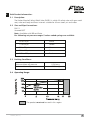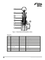
1
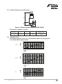
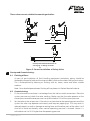
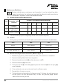
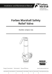
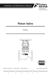
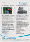
Installation and Maintenance Manual
Forbes Marshall Safety
Relief Valve
FMSRV (DN 15)
ProductHUB
Installation and Maintenance Guide
ANDROID APP ON
G oogl e play
Forbes Marshall
Forbes Marshall Arca
Codel International
Krohne Marshall
Forbes Solar
Forbes Vyncke
Forbes Marshall Steam Systems
Table of Contents
1.
Preface .................................................................................1
2.
Important Safety Notes
3.
Brief Product Information .....................................................3
4.
Product Working Principle ...................................................6
5.
Installation Guidelines ..........................................................6
6.
Startup and Commissioning...................................................7
7.
Maintenance Guidelines ......................................................8
8.
Troubleshooting ...................................................................9
9.
Available Spares ..................................................................9
10.
Warranty Period ...................................................................9
......................................................1
PLEASE NOTE - Throughout this manual this cautionary symbol is used to
describe a potential damage or injury that might occur if the safety
considerations are overlooked. This symbol denotes CAUTION, WARNING or
DANGER.
Forbes Marshall Safety Relief Valve
1.
Preface:
This manual is intended for anyone using, commissioning, servicing, or disposing the below
mentioned products safely and efficiently.
Forbes Marshall Safety Relief Valve. [FMSRV (DN15)]
Sizes: DN15 (1/2”)
PLEASE NOTE:
Throughout this manual the following cautionary symbol is used to describe a potential damage
or injury that might occur if the safety considerations are overlooked.
2.
Important Safety Notes:
Read this section carefully before installing/operating/maintaining the product. The
precautions listed in this manual are provided for personnel and equipment safety.
Furthermore, Forbes Marshall accepts no responsibility for accidents or damage
occurring as a result of failure to observe these precautions. Note that the product is
designed to perform for non-contaminated fluids only. A contamination in the form of
chemical, foreign particle etc. can lead to problem with product performance and life
of the product.
If these products in compliance with the operating instructions are, properly installed,
commissioned, maintained and installed by qualified personnel (refer Section 2.7) the safety
operations of these products can be guaranteed. General instructions for proper use of tools and
safety of equipments, pipeline and plant construction must also be complied with.
2.1 Intended use:
Check if the product is suitable for intended use/ application by referring to the installation
and maintenance instructions, name plates and technical information sheets.
i)
The product is suitable for use as defined in the technical information sheet. In case the
need arises to use the product on any other fluid please contact Forbes Marshall for
assistance.
ii)
Check for the suitability in conformance to the limiting conditions specified in technical
information sheet of the product.
iii)
The correct installation and direction of fluid flow has to be determined.
iv)
Forbes Marshall products are not intended to resist external stresses, hence necessary
precautions to be taken to minimize the same.
2.2 Accessibility and Lighting:
Safe accessibility and working conditions are to be ensured prior to working on the product.
FMSRV (DN 15)
1
2.3 Hazardous environment and media:
The product has to be protected from hazardous environment and check to ensure that no
hazardous liquids or gases pass through the product.
2.4 Depressurizing of systems and normalizing of temperature:
Ensure isolation and safety venting of any pressure to the atmospheric pressure. Even if the
pressure gauge indicates zero, do not make an assumption that the system has been
depressurized.
To avoid danger of burns allow temperature to normalize after isolation.
2.5 Tools and consumables:
Ensure you have appropriate tools and / or consumables available before starting the work.
Use of original Forbes Marshall replacement parts is recommended.
2.6 Protective clothing:
Consider for the requirement of any protective clothing for you/ or others in the vicinity for
protection against hazards of temperature (high or low), chemicals, radiation, dangers to
eyes and face, noise and falling objects
2.7 Permits to work:
All work to be carried out under supervision of a competent person. Training should be
imparted to operating personnel on correct usage of product as per Installation and
Maintenance instruction. “Permit to work” to be complied with (wherever applicable), in
case of absence of this system a responsible person should have complete information and
knowledge on what work is going on and where required, arrange to have an assistant with
his primary goal and responsibility being safety. “Warning Notices” should be posted
wherever necessary.
2.8 Handling:
There is a risk of injury if heavy products are handled manually. Analyze the risk and use
appropriate handling method by taking into consideration the task, individual, the working
environment and the load.
2.9 Freezing:
Provision should be made to protect systems which are not self-draining, against frost
damage (in environment where they may be exposed to temperatures below freezing point)
to be made.
2.10 Returning products:
Customers and Stockist are reminded that, when returning products to Forbes Marshall they
must provide information on any hazards and the precautions to be taken due to
contamination residues or mechanical damage which may present a health, safety or
environmental risk.
This information must be provided in writing including Health and Safety data sheets
relating to any substances identified as hazardous or potentially hazardous.
2
Forbes Marshall Safety Relief Valve
3.
Brief Product Information:
3.1 Description:
The Forbes Marshall Safety Relief Valve FMSRV is a high lift safety valve with gun metal
seat, valve and body and brass internals suitable for use on steam, air and water.
3.2 Size and Pipe Connections:
DN 15
Screwed BSPT
Note : Available with IBR certificate
For following set pressure ranges 5 colour coded springs are available
00 to 15 psi
White
15 to 35 psi
Yellow
35 to 75 psi
Green
75 to 125 psi
Blue
125 to 250 psi
Red
3.3 Limiting Conditions:
Minimum blow off pressure
0.34 bar g
Maximum blow off pressure
17.3 bar g
3.4 Operating Range:
The product must not be used in this region.
FMSRV (DN 15)
3
Figure 1: Forbes Marshall Safety Relieve Valve
Materials:
4
Sr. No.
Part
Material
Standard
1
Body
G.M
BS 1400
2
Valve Head
G.M.
BS 1440 LG 2
3
Spring
Spring Steel
I.S. 4454 part IV
4
Spindle
Brass
I.S.4170
5
Bonnet
Brass
I.S.4170
6
Adjustment Cap
Brass
I.S.4170
7
Lock Nut
Brass
I.S.4170
8
Ring
C 20
I.S.2062
9
Dowel Pin
SS 304
ASTM A 276
Forbes Marshall Safety Relief Valve
3.5 Product Dimension and Drawing:
Figure 2: Dimensional drawing of FMSRV (DN15)
Dimensions: (approx. ) in mm:
Size (DN)
A
B
C
Weight (kg)
15
87
23
30
0.42
3.6 Capacity Chart:
Discharge capacities with 10% accumulation above the set pressure
for various fluids shown below
600
500
400
STEAM
kg/hr
300
200
100
0
0
2
4
6
Set pressure in bar g
8
10
12
8
10
12
14
16
18
7000
6000
5000
4000
kg/hr
WATER
3000
2000
1000
0
0
2
4
6
14
16
18
Set pressure in bar g
150
125
100
AIR
kg/hr
75
50
25
0
0
2
4
6
8
10
12
14
16
18
Set pressure in bar g
FMSRV (DN 15)
5
4.
Product Working Principle (Refer to Figure 1):
The Forbes Marshall Safety Relief Valve is normally set at a pressure which is 10% above the
working pressure of the system. This is referred to as a set pressure. When the safety pressure
reaches blow off pressure the safety valve opens to its full lift to discharge full capacity. The valve
closes at reset pressure.
The steam enters the Safety Relief Valve through the inlet from the bottom. When the steam
reaches the set point of the FMSRV it lifts the valve head (2) off the valve seat, working against the
spring (3) present inside the valve body (1). As long as the steam pressure exceeds the set
pressure, the valve remains open. As soon as it comes below the set pressure, the spring force
pushes the valve head (2) back onto the valve seat.
5.
Installation Guidelines (Refer to Figure 3):
Note: Before implementing any installations observe the 'Important Safety notes” in
section 2. Referring to the Installation and Maintenance Instructions, name-plate and
Technical Information Sheet, check that the product is suitable for the intended
installation.
6
1.
The Forbes Marshall Safety Relief Valve should always be mounted vertically upwards with
its main axis kept vertical.
2.
There should be no intervening valve or any fitting between the piping and the safety relief
valve which could isolate the FMSRV (Refer to fig. 3a).
3.
The inlet connection should never be smaller than the valve inlet and output pipe should be
either equal or larger than the valve outlet.
4.
Where the outlet pipework is directed upwards a small bore drain should be provided at the
lowest point. Take the drain to a place where discharge will not create any hazard or
inconvenience (Refer to fig. 3b).
5.
Each safety relief valve should have its own discharge pipe.
6.
Make sure that safety relief valve is set to the correct pressure.
7.
Safety relief Valves should not be insulated.
8.
Excessive pressure loss at the inlet of a safety relief valve when it operates will cause
extremely rapid opening and closing of the valve, observed as chattering or hammering. This
may result in reduced capacity as well as damage to seating faces and the other parts of the
valve. When normal pressure is restored it is possible that the valve will leak. Therefore the
Valve should be fitted 8-10 pipe diameters downstream of Converging or Diverging Fittings
or Bends (Refer to fig. 3c)
Forbes Marshall Safety Relief Valve
These valves are not suitable for mounting on boilers
3a
3b
8-10 Pipe Diameters downstream of
converging ‘Y’ fittings or bends.
3c
-
Figure 3: Correct Installation of Safety Valve
6.
Startup and Commissioning :
6.1 Flushing of lines:
As part of pre-installation all fluid handling equipment particularly piping should be
thoroughly cleaned of scale and the internal debris which accumulates during construction.
This is accomplished by blowing or flushing with air, steam, water and other suitable
medium.
Note: For a detailed procedure on flushing of lines please visit Forbes Marshall website.
6.2 Commissioning:
1.
Fit the valve and ensure there is no leakage from the inlet or outlet connections. Raise the
system pressure and check the valve working. Make sure that the valve operates at the
correct pressure and the over pressure is only be limited to 10% of the system pressure.
2.
Set the valve at the set pressure. If the valve is set too close to the operating pressure of the
system the valve may operate continuously and keep on popping up. This may result in
reduced capacity as well as damage to seating faces and the other parts of the valve. It will
also fail to close satisfactorily when normal operating pressure is restored. Hence it is
advisable to set it at 10% higher than the operating pressure.
FMSRV (DN 15)
7
7.
Maintenance Guidelines :
Before undertaking any maintenance on the product it must be isolated from both
supply line and return line and any pressure should be allowed to safely normalize to
atmosphere. The product should then be allowed to cool.
7.1 Routine and Preventive Maintenance:
S.No
1
2
3
Parameters to be
checked
Visual inspection for
leakages
Testing of Safety
relief Valve
Frequency for checking and maintaining
Immediately
Daily
weekly Monthly Quarterly
Half
yearly
Annually
Y
Y
Cleaning of internals
Y
*Re-certification by respective regulatory authorities as and when required
7.2 Tool Kit:
To carry out any maintenance of the SRV please use the tools mentioned in the table below.
Part
Tool
Size
Bonnet
open spanner
22mm (A/F)
Valve seat
box spanner
28 mm (A/F)
Adjust bolt and lock nut
open spanner
22mm (A/F)
7.3 Maintenance/Replacement Procedure : (Refer to Figure 1)
8
1.
Before carrying out any maintenance on the valve, make sure that it is isolated first.
2.
Remove the Safety Relief Valve from the pipeline.
3.
Remove the adjustment bolt (6) and the adjustment nut (7)
4.
Remove the bonnet (5) of the valve
5.
Pull out the spindle (4) off the body (1) to expose the valve head (2) with the spring (3)
out of the body.
6.
Clean and lap the valve seat on the valve head in oscillation motion.
7.
Reassemble in the reverse manner.
8.
Fit the valve back on the pipeline. Set the pressure to 10% above the working pressure
of the system. Use the adjustment bolt, nut and the pressure gauge present
downstream to set the pressure.
Forbes Marshall Safety Relief Valve
8.
Troubleshooting:
If the expected performance is unachievable after the installation of the safety relief valve, check
the following points for appropriate corrective measures.
Failure Mode
Possible Cause
Remedy
Check for spring
Refer to the spring ranges given in section 3.2
range
Valve
Leakage
Valve seating
surface dirty or
damaged
Not
Check the
Releasing the pressure setting
of the valve
Pressure
9.
It is usually sufficient to clean the seating surfaces and
reassemble. If the seating surface has been damaged it is
necessary to re-lap. When reassembling all foreign matter and
scales should always be cleared away from the surrounding
components, all lapping paste removed and seating surface
cleaned.
1. It should be 10% above the working pressure of the
system.
2. Make sure the spring range selected is not higher than
mentioned in section 3.2 for a given pressure range.
Available Spares:
SPARE CODE
SPARE PART
S2250520
SPARES KIT: DN15 VALVE HEAD AND SPINDLE KIT FOR FMSRV (DN 15) (STEAM &
S2250521
SPARES KIT: SPRING KIT FOR DN15 FMSRV (DN 15) - 05 - 15 – PSI
S2250522
SPARES KIT: SPRING KIT FOR DN15 FMSRV (DN 15) - 15 - 35 – PSI
S2250523
SPARES KIT: SPRING KIT FOR DN15 FMSRV (DN 15) - 35 - 75 – PSI
S2250524
SPARES KIT: SPRING KIT FOR DN15 FMSRV (DN 15) - 75 - 125 – PSI
S2250525
SPARES KIT: SPRING KIT FOR DN15 FMSRV (DN 15) - 125 - 250 – PSI
S2250529
SPARES KIT: DN15 VALVE HEAD AND SPINDLE KIT FOR FMSRV (DN 15) (AIR
How to Order:
Example: Forbes Marshall Safety Valve, FMSRV , DN15 with BSPT ends & a set pressure of 6 bar g.
Note : available with IBR certificates
How to Order Spares:
Always order spares by using the description given in the column headed available spares. For
codes refer user manual.
10. Warranty Period:
As per the ordering information and agreement in the contract
FMSRV (DN 15)
9
Forbes Marshall
B-85, Phase II, Chakan Indl Area
Systems Pvt. Ltd.
Sawardari, Chakan
(Formerly Spirax Marshall Pvt. Ltd.)
Tal. Khed, Dist. Pune 410501. INDIA. Opp 106th Milestone
Tel : +91 02135 393400
Email : [email protected]
Forbes Marshall Steam
Bombay Poona Road, Kasarwadi,
Pune 411 034. INDIA.
Tel.: 91(0)20-27145595, 39858555
CIN No : U27109PN1959PTC011334
www.forbesmarshall.com
Doc# FMSS/0415/UM-FMSRV(DN15)/V1.R0
ALL CONTENTS HEREIN ARE THE PROPERTY OF FORBES MARSHALL PRIVATE LIMITED (“FMPL”) OR FORBES MARSHALL STEAM SYSTEMS PRIVATE
LIMITED (“FMSSPL”), AS THE CASE MAY BE, AND HAVING PROTECTION UNDER THE INTELLECTUAL PROPERTY RIGHTS. ANY REPRODUCTION,
DISTRIBUTION OR DISCLOSURE WITHOUT PRIOR WRITTEN PERMISSION IS PROHIBITED.
The information in this document is subject to change without notice. FMPL or its Subsidiaries, Associates, Affiliates and Group Companies assume no
responsibility for inaccuracies or omissions and specifically disclaim any liabilities, losses, or risks, personal or otherwise, incurred as a consequence,
directly or indirectly, of the use or application of any of the contents of this document.