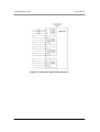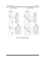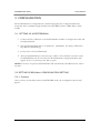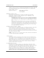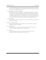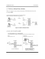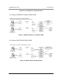
1
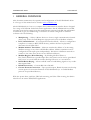
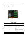
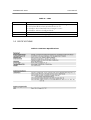
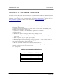
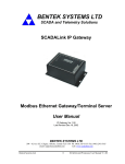
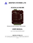
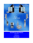
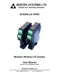
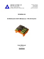
BENTEK SYSTEMS LTD
#315, 3750 - 46 Ave S.E.
Calgary, Alberta, T2B 0L1
ph: (403) 243-5135 fax: (403) 243-5165
SCADA & Telemetry
Control Systems
Instrumentation
Operator Interfaces
Data Communications
SCADALink
SCADASwitch SS10 Multiplexer / RS-232 Switch
User Manual
Feb 15, 2012
www.scadalink.com
TABLE OF CONTENTS
1 GENERAL OVERVIEW ............................................................................................. 1
2 HARDWARE OVERVIEW ........................................................................................ 2
2.1. HARDWARE ...................................................................................................... 2
2.2 SPECIFICATIONS ............................................................................................ 3
3 CONFIGURATION .................................................................................................... 6
3.1 SETTING UP HYPERTERMINAL ................................................................... 6
3.2 SETTING SCADASwitch CONFIGURATION SETTING .......................... 6
3.2.1 General........................................................................................................ 6
3.2.2 Settings ........................................................................................................ 7
4 TYPICAL OPERATING MODES ........................................................................... 10
4.1 Mux MODE ......................................................................................................... 10
4.2 LOI / RS-232 SWITCH MODE .................................................................... 10
4.3 Modbus ADDRESS TRANSLATION MODE .............................................. 11
4.4 Modbus WRITE BLOCKING MODE ............................................................ 11
4.5 RS-232 RADIO KEYING MODE .................................................................. 12
4.6 RS232 / RS485 CONVERSION MODE ..................................................... 12
APPENDIX A – UPGRADE FIRMWARE ................................................................. 13
SCADASwitch SS10
User Manual
1 GENERAL OVERVIEW
This document summarizes the operation and configuration of the SCADASwitch SS10.
A soft copy of this manual can be found at www.scadalink.com.
The SCADASwitch is a low cost, compact data communications interface device designed
for a range of SCADA & Industrial control applications. The SCADASwitch has two RS232 input ports and an output port that simultaneously supports both RS-232 and RS-485
connections to give it a flexible range of functions. It can be configured via terminal
software to do the following:
•
•
•
•
•
•
•
Multiplexing – Allows 2 Master devices to share a single communication channel
(Note: only works for Poll/Response-type protocols such as Modbus or ROC).
LOI / RS-232 Switch - (Local Operator Interface Mode) - Allows a configuration
computer to connect to RTU/EFM device(s) without the need to physically
disconnect the SCADA Host
Modbus Address Translation - SS10 can translate the address of an incoming
Modbus message to any other valid Modbus address. Address translation can be
configured on both input ports independently. This allows 2 different networks to
connect to the same slave device on two different addresses.
Modbus Register Write Blocking – By blocking Modbus Writes to
PLC/RTU/EFM from a specific Input Port, this feature can be used to grant ReadOnly access to one SCADA host while allowing full access to a second host.
RS-232 Radio Keying – Allows an RTU with no handshaking signals to key a radio
that requires RTS.
RS-485 Conversion - Converts RS-232 to RS-485
Custom Protocol Conversion – Upon special request, Bentek Systems can develop
custom protocol conversion firmware for SCADASwitch (i.e. to enable Modbus
protocol for specialized devices)
With low power draw, small size, DIN rail mounting, and Class I Div 2 rating, the SS10 is
ideal for use in remote EFM/RTU applications.
Feb 15, 2012
General Overview
1 of 13
SCADASwitch SS10
User Manual
2 HARDWARE OVERVIEW
2.1. HARDWARE
The SS10 is shown in Figure 1 below:
COM 1
COM 2
COM 3: RS-232
COM 3: RS-485
Input
Power
Switched
Power
Output
LEDs
Figure 1: SS10 Hardware
Table 1: Connectors
CONNECTOR
Input Power
Switched Power
Output
COM1
Tx, Rx, GND
COM2
Tx, Rx, GND, RTS, CTS
COM3: RS-232
Tx, Rx, GND, RTS, CTS
COM3: RS-485
Tx+, Tx-, Rx+, Rx-, GND
Feb 15, 2012
PINS
PWR, GND
SWP, GND
DESCRIPTION
9-30VDC,Reverse Polarity Protection
Vin-0.5V@ 2.5A peak or 1.5A
continuous
RS-232, DB9F (DCE) Used for
Configuration and LOI or second Host
for Multiplexing
RS-232, 5 Pin Terminal Block, usually
used for Primary Modem or SCADA
input
RS-232 Output, 5 Pin Terminal Block,
usually used for slave connection or
radio network
RS-485 Output, 5 Pin Terminal Block,
usually used to connect to slave devices
or multidrop networks
Hardware Overview
2 of 13
SCADASwitch SS10
User Manual
Table 2: LEDs
LEDS
STATUS
Tx
Rx
DESCRIPTION
1. Flashes every second while waiting for Entry to Configure Mode
2. Off in Run Mode when Switched Power is off
3. Solidly lit when Switched Power Output is active
4. Solidly lit when in Configure Mode
Flashes when there is data coming from COM3
Flashes when there is data going to COM3
2.2 SPECIFICATIONS
Table 3: Hardware Specifications
Feb 15, 2012
Hardware Overview
3 of 13
SCADASwitch SS10
User Manual
Figure 2: Serial Port Signal Flow Direction
Feb 15, 2012
Hardware Overview
4 of 13
SCADASwitch SS10
User Manual
Figure 3: COM 3 RS-485 Wiring
Feb 15, 2012
Hardware Overview
5 of 13
SCADASwitch SS10
User Manual
3 CONFIGURATION
The SCADASwitch is configured with a terminal program such as Hyperterminal and
connected with a standard straight thru RS-232 cable DB9 Female to DB9 Male to SS10
COM 1.
3.1 SETTING UP HYPERTERMINAL
1. Connect the PC COM Port to the SCADASwitch COM1: via straight thru cable and
run Hyperterminal.
2. Start up Hyperterminal and set to 9600 N 8 1 (9600 Baud, No Parity, 8 Data Bit, 1
Stop Bit No Handshaking).
3. Cycle power to the SCADASwitch
4. After the SCADASwitch is rebooted, type <ESC> twice within 8 seconds to enter
CONFIGURE mode. If successful, the SCADASwitch Configuration Menu will
appear. If not, re-cycle the power and try again.
NOTE: If no keys are pressed, SCADASwitch will automatically enter RUN mode after 8
seconds.
3.2 SETTING SCADASwitch CONFIGURATION SETTING
3.2.1 General
Once you have successfully entered CONFIGURE mode, the Configuration Screen will
appear.
Feb 15, 2012
Configuration
6 of 13
SCADASwitch SS10
User Manual
Figure 4: Configuration Screen
3.2.2 Settings
1-3: Serial Port Parameters
Multiplex (Mux) Mode: (default mode)
Both Input ports (COM1 & COM2) are able to communicate to devices connected
to the Output Port (COM3). Requests from the input ports are sent on a first come
first served basis and messages waiting to be sent are buffered internally until output
port is available. Mux mode is used to transparently share a single serial port between
two master devices.
Local Operator Interface (LOI) Mode:
COM2 is used as normal communications port to end devices connected to COM3
(Output port). COM1 is left unconnected and is used for Local interfacing to end
devices. The SS10 automatically detects the connection of a RS232 device (eg.
Laptop) on COM1 and blocks all traffic from COM2 until the cable is disconnected
from the device on COM1. This mode is used to allow the operator to connect
directly to the end devices on COM3 for local configuration, calibration etc. without
being disrupted by traffic from COM2.
Baud Rate and Data Format:
All three com ports can be configured to have independent baud rates from 1200115200 baud. SS10 will automatically handle baud rate conversion between ports set
to different rates. (default baud rate = 9600).
Feb 15, 2012
Configuration
7 of 13
SCADASwitch SS10
User Manual
All three com ports can also be configured with independent data formats. SS10 will
automatically handle data format conversion between ports set to different data
formats. (default = N:8:1)
Supported settings are:
-None, even, or odd Parity.
-8 or 9 Data bits.
-1 or 2 stop bits.
Handshaking: (default = none)
RTS or RTS/CTS handshaking are available on COM2 and COM3. When
handshaking is enabled user will be prompted to enter a “RTS Delay” value.
Handshaking operation is as follows:
-RTS: When data is ready to be sent out via port in which RTS handshaking
is enabled, RTS line is driven high. After the time specified by “RTS Delay”
value, Message data is sent. After message has completed RTS line is driven
low.
-RTS/CTS: When data is ready to be sent out via port in which RTS/CTS
handshaking is enabled, RTS line is driven high. SS10 waits for CTS to be
asserted by the connected device. Once CTS signal is received the SS10 waits
for the value of “RTS Delay” before sending message data. After message
has completed RTS line is driven low.
No Response Timeout: (default = 2000ms)
COM3 (Output Port) configuration requires a “No Response Timeout” value. This
value is the amount of time the SS10 will wait for a response from a device
connected to COM3 before giving up and allowing the next request to be sent.
This value should be set longer than the maximum expected response time from the
end devices connected to COM3.
NOTE: In Mux mode, the no response timeout values on both hosts should be set
to “at least” twice the value set on the SS10.
4. Timer Options:
The SS10 has a built in general purpose timer which controls the switched power
output (SWP) on the two terminal block next to the power input. The timer can be
programmed to turn on at a specified interval for a specified amount of time (in
minutes) The SWP output sources power and can provide up to 2.5A peak, or 1.5A
continuous. The Timer can be used to turn on a sensor or device for a limited
amount of time in order to save power.
5-6. Modbus Write Protection:
Both Input ports (COM1 & COM2) can be independently configured to block
modbus write commands. When Enabled the SS10 will block all write commands to
both holding registers and coil registers incoming on that port. When write
protection is enabled, user can configure up to six ranges of register addresses (6
holding ranges and 6 coil ranges) in which write commands can be allowed if
required, all other writes to any other registers except those ranges specified are
blocked. In some cases a write might be necessary in order to populate an index for
Feb 15, 2012
Configuration
8 of 13
SCADASwitch SS10
User Manual
historical data polling (eg. Enron Modbus) This feature allows the user to configure
the device so that the host device can still poll historical data but does not have write
access to the rest of the device registers.
7-8: Modbus Address Translation / Blocking:
Both Input ports (COM1 & COM2) can be independently configured to Translate,
Pass, or Block any message containing a user specified modbus addresses within the
valid range of 1-256. When translating the SS10 can convert incoming messages for
one address and send them out for another address, then convert the response back
to the original address. The SS10 can also block or pass specific addresses. The user
can choose to either block or pass all other addresses not specified in the table.
9: Advanced Settings:
These settings are for specific applications. Consult with Bentek Systems Ltd. before
adjusting these settings.
10. Return to Factory Defaults:
This option resets all configuration parameters to Factory Defaults. All current
configuration settings are cleared.
11. Firmware upgrade:
This Option is used to upgrade the current firmware running on the SS10. All
current configuration settings are cleared. (See Appendix)
12. Save and Exit:
Entering this option or pressing esc from the main menu screen exits the
configuration mode and automatically reboots the SS10.
Feb 15, 2012
Configuration
9 of 13
SCADASwitch SS10
User Manual
4 TYPICAL OPERATING MODES
These are examples of some common modes that the SCADASwitch can be used in.
4.1 Mux MODE
Figure 5: Modbus Multiplex Mode
4.2 LOI / RS-232 SWITCH MODE
Feb 15, 2012
Typical Operating Modes
10 of 13
SCADASwitch SS10
User Manual
Figure 6: Local Operator Interface Mode
4.3 Modbus ADDRESS TRANSLATION MODE
Figure 7: Modbus Address Translation Mode
4.4 Modbus WRITE BLOCKING MODE
Figure 8: Modbus Write Blocking Mode
Feb 15, 2012
Typical Operating Modes
11 of 13
SCADASwitch SS10
User Manual
4.5 RS-232 RADIO KEYING MODE
Figure 9: RS-232 Radio Keying Mode
4.6 RS232 / RS485 CONVERSION MODE
Figure 10: RS-232 / RS-485 Conversion Mode
Feb 15, 2012
Typical Operating Modes
12 of 13
SCADASwitch SS10
User Manual
APPENDIX A – UPGRADE FIRMWARE
The SS10 factory ships with the latest firmware. Under normal conditions, the firmware does
not need to be upgraded. In the event that Bentek System issues a critical update to the
firmware, or customizes it for your application, follow these instructions to upgrade. If you
have problems upgrading, contact Bentek Systems at www.scadalink.com or
[email protected]
1. Open Hyperterminal, set to COM1, 9600 Baud, No Parity, One Stop Bit,
Hardware Flow Control.
2. Connect a standard straight-thru serial cable ( at least 5 wire: Tx, Rx, RTS, CTS,
GND) from computer to DB9 port.
3. Connect 10-30VDC to SCADASwitch Input Power terminals
4. Cycle power on
5. While status light is flashing hit ESC twice within 8 seconds
6. If main menu appears, select Option 11, Upgrade Firmware, otherwise repeat
steps 4 & 5
7. Wait for prompt “Erase complete, press any key”
8. Press any key ONCE
9. When prompted with the message “waiting for program…” Click transfer from the
top menu bar and select “Send Text File”
9. Browse for the SCADASwitch Firmware file and select it
10. Spade characters will appear until file is finished loading. If no Spade characters
appear, cycle power and start process again.
11. Cycle power
Table 4: Programming Cable Pinout
Signal Name
Rx
Tx
Gnd
RTS
CTS
Feb 15, 2012
DB9F Pin
2
3
5
7
8
Appendix A
DB9M Pin
2
3
5
7
8
13 of 13