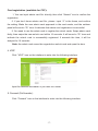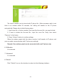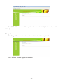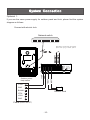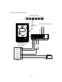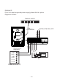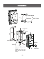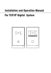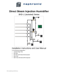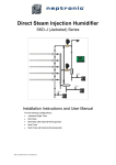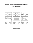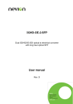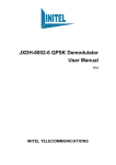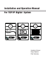
1
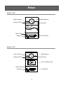
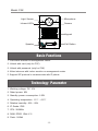
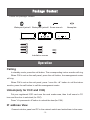
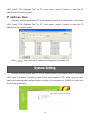
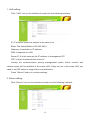
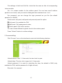
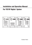
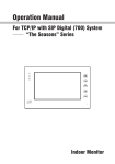
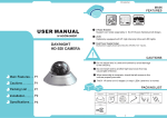
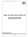
Installation and Operation Manual
For TCP/IP Digital System
Outdoor Panel
Help Station
Flat Camera
Remark
Please follow the user manual for correct installation and testing, if
there is any doubt please call our tech-supporting and customer
center.
Our company applies ourselves to reformation and innovation of
our products. No extra informing for any change. The illustration
shown here only used for reference, if there is any difference
please take the actual product as standard product.
CATALOG
Product Picture ........................................................1
Basic Functions........................................................2
Technology Parameters ...........................................2
Package Content......................................................3
Operations................................................................3
System Setting .........................................................4
System Connection................................................10
Installation ..............................................................13
Care and Maintenance...........................................14
Picture
Model:C3S
Light Sensor
Microphone
Infrared LEDs
Camera
Name Tag
Speaker
Call Button
Light Sensor
Microphone
Infrared LEDs
Camera
Model:C3C
Card Reader Area
Name Tag
Call Button
Speaker
-1-
Model:C3K
Light Sensor
Microphone
Infrared LEDs
Camera
Keypad
Call Button
Speaker
Basic Functions
1. Call indoor monitor or management center.
2. Unlock with card (only for C3C).
3. Unlock with password (only for C3K).
4. Video intercom with indoor monitor or management center.
5. Support SIP protocal to communicate with IP phone.
Technology Parameter
1. Working voltage: DC 12V
2. Rated power: 6W
Technology Parameter
3. Standby power consumption: 2.5W
4. Operating temperature: -10℃~+55℃
5. Relative humidity: 20%~93%
6. IP Grade: IP65
7. CPU: 350MHz
8. RAM: DDR2 1Gbit X 2
9. Flash: 16Gbit
-2-
Package Content
Check the package content:
Waterproof jacket1 Waterproof jacket2 Screw wrench
Waterproof jacket3
Cover
Nameplate
Waterproof stricker
Installation screws
Operation
Calling
In standby mode, press the call button. The corresponding indoor monitor will ring.
When C3S is set as the wall panel, press the call button, the management center
will ring.
When C3K is set as the unit panel, press “room No.+#” button to call the indoor
monitor, press the call button to call the management center.
Unlock(only for C3C and C3K)
Put your registered IC/ID card near the card reader area, then it will sound a "Di"
tone and the door is unlocked (for C3C).
Press “#+password+#”button to unlock the door(for C3K).
IP address View
Connect outdoor panel and PC in the network switch and make them in the same
-3-
LAN. Install “700 Upgrade Tool” in PC, and press “search” button to view the IP
address of the outdoor panel.
IP address View
Connect outdoor panel and PC in the network switch and make them in the same
LAN. Install “700 Upgrade Tool” in PC, and press “search” button to view the IP
address of the outdoor panel.
Click
icon, then the IP address will display in the frame of IP.
System Setting
Connect outdoor panel and PC in the network switch and make them in the same
LAN. Input IP address of outdoor panel in the web browser of PC, then input the user
name and password(the default name is admin, the password is 123456) to enter into
the following interface:
-4-
1. LAN setting:
Click “LAN” icon on the interface to enter into the following interface:
IP: IP address should be unique in the same LAN.
Mask: The default Mask is 255.255.255.0.
Gateway: It depends on IP address.
DNS: It depends on LAN.
Server IP: It is the same as the IP address of management PC.
NTP: It refers to network time protocol.
Usually, the communication among management center, indoor monitor and
outdoor panel will be available in the same LAN; if they are not in the same LAN, you
need to set SIP server to support the communication.
Press “Submit” button to confirm settings.
2. Device setting:
Click “Device” icon on the interface to enter into the following interface:
-5-
The settings of build and Unit No. should be the same as that of corresponding
indoor monitor.
No.: It is unique number for the outdoor panel. You can have max.9 outdoor
panels in one house, and you need to distinguish their numbers from 1 to 9.
Sys password: you can change the login password as you like (the default
password is 123456).
Panel mode: unit panel, wall panel and personal panel for option.
1 Unit panel: It is available for C3K;
2 Wall panel: Call management center;
3 Person panel: Call indoor monitor.
You can choose different ring back tone for the outdoor panel.
Press “Submit” button to confirm settings.
3. Access setting:
Click “Access” icon on the interface to enter into the following interface:
Unlock timeout: After 1~9 seconds, the door lock is open.
Unlock delay: The door lock is open for 0~9 seconds.
Unlock password: It is used for unlocking the door, the default is 0000 (only
available for C3K, and the password is 4 digits at most).
Elev refer: It is reserved.
-6-
Card registration (available for C3C):
1. You can input admin card No. directly, then click “Submit” icon to confirm the
registration.
2. If you don’t know admin card No., please input “0” in the frame, and confirm
the setting. Make the new admin card approach to the card reader, and the outdoor
panel will sound a “Di” tone. It indicates that admin card registration is successful.
3. You need to use the admin card to register the unlock cards. Swipe admin card
firstly, then swipe the new unlock card within 10 seconds. It will sound a “Di” tone and
indicate the unlock card is successfully registered. If exceeds the time, it will be
delayed for 10 seconds.
Note: the admin card cannot be regarded as unlock card and open the door.
4. VOIP
Click “VOIP” icon on the interface to enter into the following interface:
Input the relevant information if you have SIP server.
5. Forward (Call transfer):
Click “Forward” icon on the interface to enter into the following interface:
-7-
The indoor monitor can be bound with IP phone No.. When someone calls it, and
there is no answer within 25 seconds, the calling will transfer to the IP phone
automatically. Please refer to the following steps:
1. Input room No. of indoor monitor, then input the Account No. you want to bind;
2. If want to delete the Account No., input the room No. firstly, then select
“Remove” in the frame;
3. Press “Submit” button to confirm settings.
When the outdoor panel calls the indoor monitor, it will transfer to IP phone, and
you can make communication with IP phone accordingly.
Remark: One outdoor panel can be connected with one IP phone only.
6. ExModule
It is reserved.
7. Advanced
It is reserved.
8. Default
Click “Default” icon on the interface to enter into the following interface:
-8-
Click “Submit” icon, now all the registered card are deleted (admin card cannot be
deleted).
9. Logout
Click “Logout” icon on the interface to enter into the following interface:
Click “Submit” icon to logout the system.
-9-
System Connection
Optional 1:
If you use the same power supply for outdoor panel and lock, please find the system
diagram as follows:
Connect with electric lock:
Network switch
Exit button: connect with the outdoor
panel. when you go outside, press it.
(Optional)
LOCK
+12V
LOCK+
Flat camera/
Outdoor panel/
Help station
+12V
GND
V+
(Optional)
GND
485+
D-SW
485
DC12V
GND
BLANK
Electric lock
CTRL
LOCK
GND
Power(UPS-DP/P)
-10-
Connect with magnetic lock:
Network switch
Exit button: connect with the outdoor
panel. when you go outside, press it.
GND
EX-BUT2
LOCK
+12V
LOCK+
Flat camera/
Outdoor panel/
Help station
+12V
EX-BUT1
CAT5e
GND
空
CTRL
LOCK
GND
Magnetic lock
电源
-11-
Optional 2:
If your lock need a seperate power supply, please find the system
diagram as follows:
Network switch
Exit button: connect with the outdoor
panel. when you go outside, press it.
EX-BUT1
EX-BUT2
CAT5e
(Optional)
NO
+12V
GND
NC
COM
Flat camera/
Outdoor panel/
Help station
+12V
GND
V+
(Optional)
GND
D-SW
485+
DC12V
485
DC Power
Supply
+18V
CTRL
LOCK1
LOCK2
Power(UPS-DP/P)
-12-
Lock
Installation
Plug
Waterproof
CAT5 Cable
m
104m
Screw holes
181mm
Screw
lHole
60mm
Drain hole: 20mm
Name tag
Build-in box
Break through the cord
hole on the bottom of the
build-in box firstly for water
draining.
Please don’t cover the
drain hold with the glass
cement.
-13-
Name tage
Cover
Care and Maintenance
1.Do not put the unit near the magnetic area such as television, video recorder etc.
2. Do not drop, knock or shake the unit.
3.Do not put the unit in hot areas. If the temperature is too high, it will shorten the using
life of the unit.
4.Do not use the wet dishcloth or volatile cleansers to clean it.
5.Do not repair the unit without any professional, or else it will harm to yourself or
damage the unit.
-14-