1
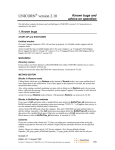
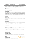
G
E
H
e
a
l
t
h
c
a
r
e
pH Monitor
User Manual
59-8310-01
Edition AD
Reading this entire manual is
recommended for full
understanding of the use of
this product.
The exclamation mark within an equilateral triangle
is intended to alert the user to the presence of
important operating and maintenance instructions in
the literature accompanying the instrument.
Should you have any comments on this manual, we
will be pleased to receive them at:
AGE Healthcare Bio-Sciences AB
S-751 82 Uppsala
Sweden
GE Healthcare Bio-Sciences AB reserves
the right to make
changes in the specifications without prior notice.
Warranty and Liability
GE Healthcare Bio-Sciences AB guarantees that the product
delivered has been thoroughly tested to ensure that it
meets its published specifications. The warranty
included in the conditions of delivery is valid only if
the product has been installed and used according to
the instructions supplied by GE Healthcare Bio-Sciences AB.
GE Healthcare Bio-Sciences AB shall in no event be liable for
incidental or consequential damages, including
without limitation, lost profits, loss of income, loss of
business opportunities, loss of use and other related
exposures, however caused, arising from the faulty
and incorrect use of the product.
Trade marks
FPLC is the exclusive trade mark of
GE Healthcare Bio-Sciences AB.
In view of the risk of trade mark
degeneration, it is respectfully suggested that authors
wishing to use these designations refer to their trade
mark status at least once in each article.
©
Copyright 1995 GE Healthcare
Bio-Sciences AB
All rights reserved. No part of this publication may
be reproduced, stored in a retrieval system or
transmitted in any form or by any means, without
permission in written form from the company.
Reading the entire manual is recommended for full
understanding of the use of this product.
Contents
1. Introduction . . . . . . . . . . . . . . . . . . . . . . . . . . . . . . . . . . . . . . . . . . . . . . . . . . . . . 5
2. General Description. . . . . . . . . . . . . . . . . . . . . . . . . . . . . . . . . . . . . . . . . . . . . . . . 6
2.1 Front panel. . . . . . . . . . . . . . . . . . . . . . . . . . . . . . . . . . . . . . . . . . . . . . . . . 6
2.2 Rear panel. . . . . . . . . . . . . . . . . . . . . . . . . . . . . . . . . . . . . . . . . . . . . . . . 7
3. Installation . . . . . . . . . . . . . . . . . . . . . . . . . . . . . . . . . . . . . . . . . . . . . . . . . . . . . . . 8
3.1 Unpacking . . . . . . . . . . . . . . . . . . . . . . . . . . . . . . . . . . . . . . . . . . . . . . . . . 8
3.2 Setting up . . . . . . . . . . . . . . . . . . . . . . . . . . . . . . . . . . . . . . . . . . . . . . . . . 8
3.3 Using the pH Monitor as a standard pH meter . . . . . . . . . . . . . . . . .8
3.4 Continuous recording of pH . . . . . . . . . . . . . . . . . . . . . . . . . . . . . . . . . .8
3.5 Calibration of the pH Monitor . . . . . . . . . . . . . . . . . . . . . . . . . . . . . . . . 9
3.6 Range adjustment . . . . . . . . . . . . . . . . . . . . . . . . . . . . . . . . . . . . . . . . . l 0
4. Operation . . . . . . . . . . . . . . . . . . . . . . . . . . . . . . . . . . . . . . . . . . . . . . . . . . . . . . l l
5. Maintenance . . . . . . . . . . . . . . . . . . . . . . . . . . . . . . . . . . . . . . . . . . . . . . . . . . . .l 2
6. Trouble-shooting . . . . . . . . . . . . . . . . . . . . . . . . . . . . . . . . . . . . . . . . . . . . . . . . l 3
7. Technical Specifications . . . . . . . . . . . . . . . . . . . . . . . . . . . . . . . . . . . . . . . . . . l 4
8. Accessories and Spare Parts. . . . . . . . . . . . . . . . . . . . . . . . . . . . . . . . . . . . . . . 1 5
3
4
1. Introduction
1. Introduction
The GE Healthcare pH Monitor (Code No. 19-8300-02,
100–120 V and 19-8301-02, 220–240 V) is a high precision
instrument which is used with the GE Healthcare flow-through
pH electrode (19-8305-01) for continuous measurement of pH in
column effluents. The pH measured can be recorded directly on the
chromatogram thus providing a valuable check on the progress of
chromatofocusing, ion exchange chromatography, affinity .
chromatography and other techniques for which pH is an
important factor.
Together with the GE Healthcare Standard pH Electrode
(Code No. 19-8306-01), the pH Monitor can be used as a high
precision pH meter for measuring the pH of eluent buffers and other
standard solutions.
5
2. General Description
2. General
Description
2.1 Front panel
pH Monitor
1
2
3
4
5
6
Fig. 1.
6
No. Item
Description
1
Digital display
3 1/2 digit LCD with two decimals. The correct pH value is
always indicated on the display even if the pH being
measured outside the range defined for the recorder.
See Low end and Span below
2
Electrode inlet
The electrode inlet is for connection of the pH electrode.
The connector must be of the BNC type
3
Low end
Potentiometer to set the lowest pH to be registred in a
pH interval
4
Span
Potentiometer to set the width in pH units
5
Zero
Potentiometer for calibration of the pH Monitor
6
Slope
Potentiometer for calibration of the pH Monitor
2. General Description
2.2 Rear panel
Fig. 2.
No. I t e m
Description
7
Mains inlet
Mains cable inlet
8
Fuse holder
Mains fuses: 1 x 63 mA for 100–120 V, 60 Hz 1 x 32 mA
for 220–240 V, 50 Hz
9
Signal output
The pH Monitor has two output ranges for the connection of
the recorder, 0-10 mV and 0-1 V
7
3. Installation
3. Installation
The pH Monitor is designed for use in normal laboratory conditions.
To minimize drift the instrument should not be placed in draught, in
direct sunlight, near the compressor or in the fan stream of cold boxes
or cold rooms.
3.1 Unpacking
Carefully unpack the pH Monitor. Check the contents against the
packing list supplied. Inspect for any damage that may have occurred
during transit. Report any damage immediately to the local
GE Healthcare representative and to the transport company
concerned.
3.2 Setting up
1. Check that the fuse holder are fitted with the correctly rated fuse.
2. Check that the voltage of the pH Monitor is correct. Connect the
instrument to a grounded mains outlet. Since the instrument only
consumes 1.5 VA, there is no ON/OFF switch and the instrument
may be left connected to the mains. In this way there is no need for
a warm-up period and the pH Monitor is always ready for use.
3.3 Using the pH
Monitor as a
standard
pH meter
1. Connect the Standard pH electrode (Code No. 19-8306-01) to the
electrode connector (Fig. 1).
2. Calibrate the pH Monitor according to the procedure in
Section 3.5.
3. The instrument is ready for use.
3.4 Continuous
recording of
1. Connect the appropriate output (Fig. 2:9) to a recorder using the
signal cable supplied with the pH monitor. Using the left and the
middle output contacts gives 0-10 mV; using the left and right gives
0-1 V (Fig. 3). To obtain the best stability use the range 0-1 V if
possible.
2. The GE Healthcare recorders REC 101/REC 102 are supplied
with pin connectors banana type with clamp connection. Connect
the screened recorder cable supplied with the pH Monitor to the
connecting clamp by pressing down the spring loaded key on the
side of the clamp connection and insert the corresponding
connecting pin on the signal cable. Release the key. Make sure
that they are properly connected. (Fig. 3)
3. Connect the recorder to the mains and press the chart drive OFF
button and the zero check button (zero).
4. Switch on the recorder.
5. Set the recorder pen at the Zero position of the chart paper by
adjusting the zero adjustment on the recorder.
8
3. Installation
6. Select the corresponding recorder input range (0-10 mV or 0-1V.)
7. Connect the Flow-through pH electrode to the electrode connector
(Fig. 1:2).
8. Release the range 0 button.
Note:
In most chromatographic uses it is advisable to connect the
detector cells in series with the following order: UV and
pH. If a UV monitor is used, connect the pH Monitor to
the outlet of the UV monitor cell.
Fig. 3. The pH Monitor connected to recorder REC 102
3.5 Calibration of
the pH Monitor
It is always necessary to calibrate a pH monitor with the pH electrode
to be used in order to adapt the pH monitor to the characteristics of
the electrode. A good laboratory routine is to recalibrate the
instrument once a day, when the electrode is replaced and if the
ambient temperature is changed.
If the Flow-through pH electrode is used, the calibration procedure
can be done with the pH electrode either fitted or disconnected from
the flow cell. Make sure to pump at least 1 ml of the new buffer
through the flow cell before adjusting the pH Monitor.
When calibrating the electrode disconnected from the flow cell, rinse
the electrode with distilled water and dry it with a soft tissue when
changing from one buffer to another.
1. Remove air bubbles from the glass membrane and the lower parts
of the connecting wires, if necessary, by shaking the electrode like
a clinical thermometer.
2. Place the electrode in a standard buffer solution with a pH close
to 7.
9
3. Installation
3. Allow the pH Monitor to stabilize and adjust it to the pH of the
buffer using the Zero switch.
4. Place the pH Electrode in standard buffer of a different pH. If the
instrument will be used predominantly in the pH range above 7,
then use a standard buffer with a pH above 7 as the second
calibration buffer. Use second calibration buffer with a pH of less
than 7, if the measuring range will be below pH 7.
5. Allow the instrument to stabilize and adjust the reading by the
potentiometer Slope to the pH of the second calibration buffer
chosen under paragraph 4 above.
6. The instrument is now calibrated.
Note:
If the pH Monitor is to be used at an extreme interval, e.g.
between pH 11-13, the calibration procedure has to be
slightly modified. Use in this case two calibration buffers,
one of pH 11.00 and one of pH 13.00. Put the electrode in
the pH 11.00 buffer and adjust the pH Monitor to show
this value with the Zero switch. Rinse the electrode with
distilled water and then put it in pH 13.00 buffer. Use the
Slope knob of the pH Monitor so that the display shows
this value. Rinse the electrode with distilled water and go
back to the pH 11.00 buffer. If the pH Monitor does not
show pH 11.00, adjust to this value with the Zero switch.
Rinse the electrode with distilled water and go back to
pH 13.00. Set the pH Monitor read-out to show the same
value.
If the pH Monitor is to be calibrated for instance between
pH 2-3, adjust and set pH 3.00 with the Zero switch and
pH 2.00 with the Slope knob. In this case also, these
operations should be performed twice.
Before calibration extremes of pH the monitor must have
been calibrated in the standard way as previously described,
e.g. betweeen pH 4 and 7 or pH 7 and 10.
3.6 Range
adjustment
The pH interval registered on the recorder is defined with the two
switches Low end and Span on the pH Monitor.
1. Choose the lowest pH to be registred on the recorder by setting
Low end at this value.
2. Choose the width in pH units of the interval to be registred on the
recorder by setting Span on this value.
Example 1:
Low End on 3, Span on 5. The pH 3-8 interval will
be recorded.
Example 2:
Low end on 4, Span on 2. The pH 4-6 interval will
be recorded.
If the pH of the solution is outside the set interval, the display will
still show the correct value even if the recorder is off-scale.
10
4. Operation
4. Operation
1. If the instrument is used for Chromatofocusing see Section “Using
the Flow-through pH Electrode in Chromatofocusing” in the
specifications instructions for the Flow-through pH Electrode.
2. Select the desired chart speed.
3. Start recording by releasing the chart drive button.
11
5. Maintenance
5. Maintenance
Wipe the instrument regularly with a damp cloth. Let the instrument
dry completely before use.
The instrument does not require any regular service. In case of failure,
contact your local GE Healthcare representative.
12
6. Trouble-shooting
6. Trouble-shooting
If the pH system is not working properly the following test procedure
can be performed in order to find out whether the pH Monitor is the
cause to the problem.
1. Set the Low end potentiometer to “Test”.
2. Set the Span potentiometer to 3.
3. Turn the Zero and Slope potentiometers fully counter-clockwise.
4. If the pH Monitor is working properly the display should now
read pH 10.00 ± pH 0.20 and the Recorder output should give
10.00 mV ± 0.20 mV (on the 10 mV range) or 1.00 V ± 0.02 V
(on the 1 V range). This means that the malfunction is to be found
in the electrode.
After this check it is necessary to recalibrate the instrument as
previously described.
13
7. Technical Specification
7. Technical
Specifications
EMC standards
Measuring range
pH 0.00-14.00
Precision
± 0.01 pH units
Display
3 1/2 digit LCD
Drift
<0.005 pH units/°C
Environment
+14 to +32 °C, 20–95% relative humidity,
84-106 kPa (840–1060 mbar) atmospheric
pressure
Input impedance
>1012 Ohm
Recorder output
0-10 mV or 0-1 V
pH electrode connector
BNC type
Mains voltage
100–120/220–240 V
Frequency
50–60 Hz
Fuse
T 63 mAL 100–120 V
T 32 mAL 220–240 V
Power consumption
1.5 VA
Dimensions (W x D x H)
215 x 105 x 65 mm
Weight
1.5 kg
~
This product meets the requirement of the EMC Directive 89/336/EEC through the harmonized
standards EN 50081-2 (emission) and EN 50082-1 (immunity)
Note: This is a class A product. In a domestic environment this product may cause radio
interference in which case the user may be required to take adequate actions.
Note: The declaration of conformity is valid for the instrument when it is:
• used in laboratory locations
• used in the same state as it was delivered from GE Healthcare Bio-Sciences AB except for
alteration described in the User Manual
• used as “stand alone” unit or connected to other CE labelled GE Healthcare products
or other products as recommended.
Safety standards
14
This product meets the requirement of the Low Voltage Directive (LVD) 73/23/EEC through the
harmonized standard EN 61010-1.
8. Accessories and Spare Parts
8. Accessories and
Spare Parts
Please order accessories and spare parts according to the designation
and code numbers below.
Designation
Code No.
No. per pack
Flow-through pH Electrode
(complete with flow cell)
19-8305-01
1
Standard pH Electrode
19-8306-01
1
Signal cable
19-6006-01
1
Fuse 62 mA SB 100/120 V
19-6235-01
2
Fuse 32 mA SB 220/240 V
18-2804-01
5
15