1
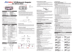
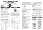
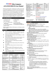
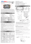
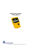
ATV/Motorcycle Computer
ACE-1000/1100 User Manual
Thanks for bought the ATV/Motorcycle computer; this manual is designed for ACE-1000/1100 series.
ACE-1000 does not have functions of thermometer and volt meter; *all descriptions relative to these functions are for ACE-1100 only.
2
RESET
1
9
4
3
7
8
English
10R-029648
RESET
10R-029648
MADE IN TAIWAN
5
6
PANEL DESCRIPTIONS
1. Tachometer Scale
2. Bar Tachometer
3. Other functions
4. Thermometer*
5. RESET Button
6. MODE Button
7. Fuel Gauge
8. RPM Warning Indicator
9. Thermo*/Fuel gauge
warning LED
FEATURES
Displays bar-graphic tachometer, digital thermometer*,
bar fuel gauge and one additional function at the same time.
Bar-graph tachometers with selectable 10,000rpm or
20,000rpm redline.
Two sets of maintenance reminders to remind you it is time to service
your bike.
Fuel gauge includes 100, 250 and 510 Ohm options for fuel meter
input resistance, as well as “fuel gauge off” mode.
Includes main unit, bracket, RPM sensing wire, thermo sensor*,
fitting kits and wiring harness.
SPECIFICATIONS
Function
Simbolo
500-10,000 rpm
1,000-20,000rpm options
Bar Tachomete
Digital Tachometer
Specifications
rpm
100-19,900rpm
Digital Thermometer*
Maximum Thermometer*
12/24 Hour Clock
Hour meter 1&2
0:00`-11H59`/23H59`
RT 1&2
0-99H59`59``
V
8.0-25.0 Volt
Total Hour Meter
Voltage Gauge*
1. Signal intensity from ignition coil is dependent on vehicle type.
2. Circles 2-5 turns around ignition coil, with more turns creating
steadily stronger signal, fewer turns creating weaker signal.
3. The RPM circuit is designed for most bikes, however partial
bikes’ signal is too strong if the RPM looks like much more than
actual RPM and unstable, please serial connect the attached 1M
Ohm resistor to solve it.
RPM-INPUT
Either One
2-5 Tuns
CDI
Ignition Coil
Thermo Sensor and Sensor Tube* :
1. The unit includes a water temperature sensor; you have to
purchase a suitable water pipe temperature sensor tube to
install the sensor easily. It is not need to purchase sensor
tube in case your bike matches PT1/8 temperature sensor
and the attachment is PT1/8 sensor.
2. Cut the water pipe, insert the temperature tube into the
pipe and secure it by attached pipe clamps.
3. Screw the sensor into the tube.
0-999999H
100Ω, 250Ω, 500Ω options or
1-7 Bar-graphic
Bar-Fuel Gauge
Maintain Reminder
RT1
or RT2
Power Input
Tachometer Sensor
Temperature Sensor*
Power Consumption
DC 12V
CDI or Ignition Coil Signal
Thermo Sensor
50uA at clock mode
1mA at on status without backlight
15mA at on status with 3 sec. backlight
25mA at on status with continue backlight
110.0mm x 55.0mm x 21.5 mm)
Dimensions
RPM sensing wire mounting:
1-9999 hours
INSTALLATION
FUNCTIONS
BAR RPM: Bar Graphic Tachometer
The bar tachometer has 10,000rpm and 20,000rpm options.
RPM: Digital Tachometer
1. It displays digital tachometer up to 19,900RPM.
2. Tachometer signal can pick up from either CDI or
Ignition Coil Signal.
Shift Warning RPM
1. The function enables you to set up a shift warning RPM.
2. Shift warning LED indicator flashes when RPM reaches
setting value, and stop flash after you shift gear.
RT 1&2: Hour Meter 1&2
1. Calculates total engine operation time from last RESET.
2. Count automatically begins with engine starting.
TT: Total Hour Meter
Mounting
1. Calculates total engine operation time from the
beginning of the computer.
2. TT data is stored in memory, and couldn’t be reset.
: 12/24 hour Clock
It displays 12 or 24 hour current time.
Rubber Pad
Washer
Spring Washer
Fixing Screw Nut
: Digital Thermometer*
1. The thermometer always displays on the right side of the screen.
2. It displays -L- C or -L- F when temperature is lower than
50 C or 122 F, and displays -H- C or –H- F when
temperature is over 180 C or 356 F.
3. The thermometer digits and warning LED indicator flash
when the thermo sensor detects temperature over the
presetting warning temperature.
MAX C or F : Maximum Thermometer*
SHIFT WARNING RPM OPERATION
Displays highest temperature achieved after last
Reset operation.
1. Press MODE button to the RPM screen; pull on the throttle
until the desired shift warning RPM.
2. Press RESET button to confirm and set up the shift warning RPM.
3. Bar-graphic tachometer and warning LED will flash to warning
you shift gear.
4. Press RESET button for 2 seconds at the RPM screen to re-adjust
the shift warning RPM.
Volt: Digital Voltage Gauge*
It checks bike’s battery and charging systems health.
Fuel Gauge
1. Have 7 bars to indicate how much fuel remains.
2. Built-in 100, 250 and 510Ohm fuel sender resistance,
the fuel bar will disappear in case you select “oFF” mode.
3. Last bar flashes to indicate low fuel level automatically.
RT1 or RT2: Maintenance Reminders
1. It has 2 maintenance reminders RT1 and RT2, which count
down the preset
entered time RT1 & RT2 since last RESET.
2. It accumulates RT1&RT2 when the count down reaches to
“0 ”, and symbols of “ RT1 or RT2” flash to remind you to
maintain oil or parts.
3. Push and hold RESET button to reset and restart the
maintenance reminder after changing oil or parts.
:Low Battery Indicator
1. The “ “ symbol flashes when the CR-2032 battery is at
low power status to remind you change the battery.
2. Remove the old battery.
3. Replace with a new CR2032 with the positive (+) pole
towards the battery cap.
4.Be sure to press RESET button at rear side after installed
the battery to sure all functions work smoothly.
BUTTON OPERATIONS
MODE BUTTON
Press the MODE button to move all functions in loop sequence
from one function screen to another.
Mode
Mode
Mode
Mode
Mode
Mode
Mode
Mode
Mode
Mode
RESET BUTTON
1. Press MODE button to get to the desired screen then press RESET
button for 2 seconds to reset hour meter, MAX thermometer*,
and MAX RPM data from stored values to zero individually.
2. TT data cannot be reset.
Backlight of Internal/Bike’s Powers:
1. The computer built-in a CR2032 battery for off road bikes in
case take away bike’s batter to reduce weight.
2. You can use both internal battery and bike’s battery at the
same time.
3. The backlight is always turned on if you connect to bike’s battery.
4. Each press of either button turns on backlight for 3 seconds then
turn off automatically when uses CR2032 only.
Clock, RPM,Temperature and fuel meter SET UP
1. Setup operations include 12/24hour clock, bar rpm scale, shift
warning RPM, numbers of engine rotation per signal, units of
thermometer*, temperature warning*, fuel meter input
resistance selection and maintain reminder setting. These must
be set up step by step. The computer will be automatic reversion
to normal mode if no button operation for 75 seconds at any
setting screen.
2. Press both MODE & RESET buttons to go into setting screen. In
setting screens, each press RESET button to increment the flashing
digit by 1 or switch units, press MODE button to confirm the digit
setting and jump to next digit or next setting screen to be set. Press
MODE button for 2 seconds at any setting screen to finish the
setting and go to normal mode.
3. It displays "12 or 24H, “XX:XX" and “A” or “P” symbols in 12H mode.
Operate buttons as described in item 2 to finish clock setting and
jump to 10,000/20,000rpm scale setting.
4. It displays 10,000rpm scale, press RESET button to convert
10,000 or 20,000rpm. Press MODE button to confirm the setting
and jump to shift RPM warning setting.
5. It displays the default "r 06500", the digit “0” flash. Follow the
item 2 of button operation to finish the shift RPM warning
setting and jump to engine specification setting.
6. It displays "RPM SPC-X.X", the default value is 1.0; there are
4 options: 1.0, 2.0, 3.0 and 0.5. It means the numbers of
engine rotation per signal. For example the value 2.0 means
the engine rotate 2 turns to output a signal.
7. Press RESET button to rotate between the 4 values. Press MODE
button to confirm the setting and go to temperature unit
setting screen.
8. It displays " C , F or OFF ", each press of RESET button
converts C , F or Off, the temperature icon and digits will
disappear when you select oFF mode ; press MODE button to
confirm temperature setting and jump to temperature
warning setting.
9. It displays "XXX" and the selected unit. Follow the item 2 of
button operation to finish the temperature warning setting
and go to fuel sensor resistance setting.
10. It displays “ 100r ” and fuel tank symbol, follow the item 2
to select 100r, 250r, 510ohm or oFF and jump to maintain
reminder setting.. The fuel meter bar will disappear if you
select oFF mode.
11. It displays “ RT1 or RT2 “symbols and “XXXX”, the default of
RT1 is 3 hours and RT2 has default of 10 hours, follow item 2
to setting a desired hours of maintain reminders and jump to
normal mode.
Clock, RPM, Temperature and fuel meter SET UP
RESET+
MODE
2 Sec
Mode
RESET
Mode 2 Sec
Mode
Clock: Hour
Mode
Maintain Reminder 2: 1~9999
Clock: Minute
Mode
Mode
Mode
RPM: 10,000 / 20,000
Maintain Reminder 1: 1~9999
Mode
Fuel Type: 100 / 250 / 510
RESET
/ off
Mode
Mode
RPM Warning: 1000 ~19,900
Temp. Warning: 40 ~ 180 C
Mode
Mode
Mode
Unit: C / F / off
Engine Signal: 0.5/1.0/2.0/3.0