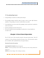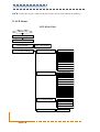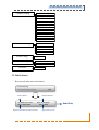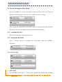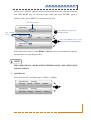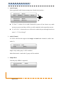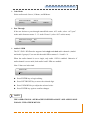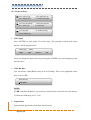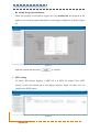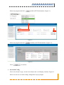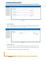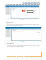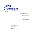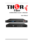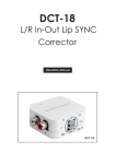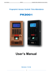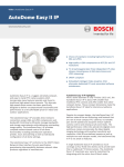
1
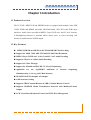
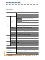
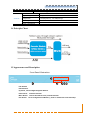
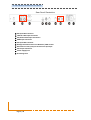
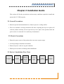
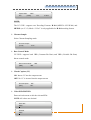
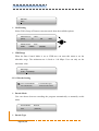
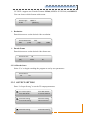
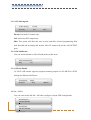
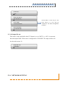
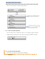
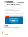
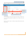
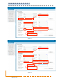
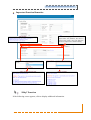
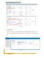
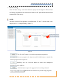
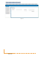
UC-550E+ MPEG-2/H.264 HD Encoder SW Version: V1.65 HW Version: V1.4.0 Web NMS Version: V1.28 About This Manual Intended Audience This manual has been written to help the end user install, integrate, and use the UC-550 MPEG2/H.264 Encoder. Some chapters require prerequisite knowledge in electronics and broadcast technologies. Disclaimer No part of this document may be reproduced in any form without the written permission of the copyright owner. The contents of this document are subject to revision without notice due to continued progress in methodology, design, and manufacturing. UPCOM Technologies shall have no liability for any error or damage of any kind resulting from the use of this document. Copy Warning This document includes some confidential information. Its usage is limited to the owners of the product that it is relevant to. It cannot be copied, modified, or translated into another language without prior written authorization from UPCOM Technologies. UC‐550E+ MPEG‐2/H.264 HD Encoder User Manual Directory CHAPTER 1 INTRODUCTION ................................................................................................................. 1 1.1 PRODUCT OVERVIEW .............................................................................................................................. 1 1.2 KEY FEATURES ........................................................................................................................................ 1 1.3 SPECIFICATIONS ...................................................................................................................................... 2 1.4 PRINCIPLE CHART ................................................................................................................................... 3 1.5 APPEARANCE AND DESCRIPTION ............................................................................................................. 3 CHAPTER 2 INSTALLATION GUIDE ........................................................................................................ 5 2.1 GENERAL PRECAUTIONS ......................................................................................................................... 5 2.2 POWER PRECAUTIONS .............................................................................................................................. 5 2.3 DEVICE’S INSTALLATION FLOW CHART .................................................................................................. 5 2.4 ENVIRONMENTAL REQUIREMENTS .......................................................................................................... 6 2.5 GROUNDING REQUIREMENTS .................................................................................................................. 7 CHAPTER 3 FRONT PANEL OPERATION ................................................................................................. 7 3.1 LCD MENU ............................................................................................................................................. 8 3.2 INITIAL STATUS ....................................................................................................................................... 9 3.3 GENERAL SETTINGS, MAIN MENU ........................................................................................................ 10 CHAPTER 4 WEB NMS OPERATION ...................................................................................................... 22 4.1 LOGIN .................................................................................................................................................... 22 4.2 OPERATION ........................................................................................................................................... 22 CHAPTER 5 TROUBLESHOOTING ......................................................................................................... 33 CHAPTER 6 PACKING LIST .................................................................................................................... 34 UC‐550E+ MPEG‐2/H.264 HD Encoder User Manual Chapter 1 Introduction 1.1 Product Overview The UC-550E+ MPEG-2/H.264 SD\HD Encoder is equipped with multiple video (SDI, CVBS, YPbPr and HDMI) and audio (SDI Embedded, AES, RCA and XLR) input interfaces. Audio can be encoded in MPEG1 Layer II, HE-AAC and LC-AAC formats. A Multiplexing function is included which allows users to select incoming ASI streams to embed into the ASI\IP output. 1.2 Key Features MPEG-2 HD/SD and MPEG-4 AVC/H.264 HD/SD Video Encoding Support for 1080I, 720P, 480I, 576I and 352*288 Video Resolution MPEG1 Layer II, HE-AAC (v1&v2) and LC-AAC Audio Encoding Supports 2 Stereo or 4 Mono Audio Encoding Support AC3 Pass Through Support for EIA 608 and EIA 708 CC (Closed Captioning) Applicable for one Seg/ISDB-T utilization (2 Streams Outputting Simultaneously: 1 one-seg and 1 Main Stream) IP (MPTS/8*SPTS) Output; ASI Output GOP Structure Setting Supports CBR (Constant Bitrate) & VBR (Variable Bitrate) Control Supports UDP/RTP Media Transmission Protocols with Multicast/Unicast Output LCD / Front Panel Keyboard Control and TCIP Web Management UC‐550E+ MPEG‐2/H.264 HD Encoder User Manual 1.3 Specifications 1×SDI, 1×CVBS, 1×YPbPr and 1×HDMI input 2×XLR, 2×RCA and 1×AES inputs Input 1×ASI input, BNC interface Input 1080i@60 1080i @59.94 Output 1920×1080, 1440×1080, 1280×1080i 1080i @50 Resolution [email protected] 720p@50 576i Video Video (one-seg) Audio 480i 1280×720, 960×720p 720×576, 704×576, 640×576, 544×576, 528×576, 352×576 720×480, 704×480, 640×480, 544×480, 528×480, 352×480 Encoding MPEG-2 HD/SD; MPEG-4 AVC/H.264 HD/SD Bit-rate 0.25Mbps~60.5Mbps Rate Control CBR/VBR GOP Structure Auto, IP, IPB, IPBB, IPBBB, IPBBBB, IPBBBBB Aspect Ratio 4:3; 16:9; 1:1; 2.35:1 Chroma 4:2:0; 4:2:2 (Applied to all resolution under MPEG2 compression) Pretreatment De-interlacing, noise reduction, sharpening Resolution 96×96, 128×96, 128×128, 192×192, 352×240, 352×288, 416×240 Encoding MPEG-2; H.264; Auto (follow the main stream format: MPEG-2 or H.264) Bit-rate 0-1.0 Mbps Aspect Ratio 4:3; 16:9; Auto (follow the main stream) Encoding MPEG-1 Layer II, HE-AAC (v1&v2), LC-AAC Sampling rate 48KHz Resolution 24-bit Bit-rate 32Kbps~384Kbps Multiplexing 1 ASI input multiplexed with local 1 channels TS Delay 1400ms - 5000ms Stream output System function Page 2 / 38 2×ASI output ports, BNC interface MPTS/8*SPTS over UDP/RTP, 10/100 Base-T Ethernet interface (UDP/RTP multicast/unicast) LCD/keyboard and web management Language: English UC‐550E+ MPEG‐2/H.264 HD Encoder User Manual Ethernet software upgrade General Dimensions 482mm×405mm×44.5mm (W × D × H) Approx weight 4.5Kg Temperature 0~45 (Operation), -20~80 (Storage) Power requirement AC110V±10%, 50/60Hz /AC 220V±10%,50/60Hz Power consumption 21W 1.4 Principle Chart 1.5 Appearance and Description Front Panel Illustration LCD window LED Indicators Up, Down, Left and Right Navigation Buttons Enter Button: Confirms Selection Menu Button: Returns One Menu Level \ Cancels Selection Lock button: Saves Configuration to Memory \ Locks or Unlocks the Front Panel Keys UC‐550E+ MPEG‐2/H.264 HD Encoder User Manual Rear Panel Illustration ① SDI Input BNC Connector ② YPbPr & CVBS Input Connectors ③ AES, RCA and XLR Input Connectors ④ HDMI Input Connector ⑤ ASI Input BNC Connector ⑥ Management Ethernet Port for Web GUI \ NMS Control ⑦ DATA Port for TSIP (Transport Stream over IP) Output ⑧ ASI Output Connectors ⑨ Power Supply/Fuse ⑩ Grounding Point Page 4 / 38 UC‐550E+ MPEG‐2/H.264 HD Encoder User Manual Chapter 2 Installation Guide This section will list the precautions and necessary conditions required to install and operate the UC-550E properly. 2.1 General Precautions Must be operated and maintained free of dust to preserve cooling airflow. The cover should be securely fastened at all times. Opening the top cover plate will void the product warranty. Do not open the top cover plate of the product while the power source is connected \ live under any circumstances. 2.2 Electric Precautions Ensure the power source of the product does not cause a power surge. Avoid operating in a humid environment. Ensure all power cords are in good condition. Ensure power switch is off during initial installation. 2.3 Device’s Installation Flow Chart Acquis ition C heck Ins talling D evice C onnecting G rouding Wire and P ower C ord C onnecting S ignal cable S etting P arameter R unning D evice UC‐550E+ MPEG‐2/H.264 HD Encoder User Manual 2.4 Environmental Requirement Item Equipment-Rack Requirements Requirement Product will require 1.2~1.5m between neighboring devices. Allow 0.8m of space from walls. Electrically Isolated, Dust Free. Datacenter Flooring Volume resistivity of ground anti-static material: 1X10⁷~1X10¹⁰Ω,Grounding current limiting resistance: 1MΩ (Floor bearing should be greater than 450Kg/㎡) Environment Temperature 5~40℃(sustainable),0~45℃(short term), Relative Humidity 20%~80% sustainable Pressure 86~105KPa Doors & Window Installing rubber strips for sealing door-gaps and dual pane glass windows are recommended. Walls Do not enclose the unit in spaces with poor airflow. Fire Protection Fire alarm system and extinguisher Power Ensure device, air-conditioning and lighting power are independent circuits. Device power requires AC 110V±10%, 50/60Hz or AC 220V±10%, 50/60Hz. Please carefully check sources before making connections. Page 6 / 38 Installing air-conditioning is recommended. 10%~90% short term UC‐550E+ MPEG‐2/H.264 HD Encoder User Manual 2.5 Grounding Requirement Good grounding is essential for a reliable product lifespan. The grounding conductor should be made of copper in order to reduce high frequency impedance. The grounding wire must be as thick and short as possible. Users should make sure the two ends of the grounding wire have good electric conductivity and are rust-resistant. Separate grounding circuits from other devices. The area of conduction between grounding wire and the device’s frame should be no less than 25 mm2. Chapter 3 Front Panel Operation The UC-550E can be fully controlled using the front panel menu buttons. The LCD consists of a 2-line 40-characer back-lit dot-matrix screen. The front panel contains the UP, DOWN, LEFT and RIGHT Menu Navigation Buttons. Keyboard Function Description LEFT/RIGHT/UP/DOWN: Menu Navigation. MENU: To cancel presently entered value and resume previous setting. Returns one menu level. ENTER: Activate changes. Save settings to memory. UC‐550E+ MPEG‐2/H.264 HD Encoder User Manual LOCK: Locks the screen / cancels the lock state. Saves unit settings to memory. 3.1 LCD Menus LCD Menu Path: Switch On Initializing General Status 1 A larm Status 2 E ncode Setting E rror T ype C heck 2.1 A udio Setting 2.1.1 A udio Input 2.1.2 A udio B it rate 2.1.3 A udio Format 2.1.4 A udio C hannel 2.1.5 A udio B it rate 2.1.6 A udio Format 2.1.7 A udio C hannel 2.1.8 A udio B it rate 2.1.9 A udio Format 2.2 V ideo Setting 2.2.1 V ideo Input 2.2.2 V ideo B it rate 2.2.3 A spect R atio 2.2.4 C hroma Sample 2.2.5 R ate C trl Mode 2.2.6 C losed C aption 2.2.7 V ideo PID 2.2.8 PC R PID 2.2.9 PMT PID 2.2.10 GOP Setting 2.2.11 V B R R ange 2.3 E ncode Setting 2.3.1 E ncode Mode 2.3.2 E ncode T ype 2.3.3 R esolution 2.3.4 E ncode Frame 2.4 E ncode Start Page 8 / 38 No / Y es UC‐550E+ MPEG‐2/H.264 HD Encoder User Manual 3 Output Setting 4 Network Setting 5 Save C onfig 6 L oad C onfig 7 V ersion 3.1 T S Mux Option 3.2 IP Null Packet 3.3 IP Out Mode 3.4 IP Out A ddress 3.5 IP Out Submask 3.6 IP Out Port 3.7 Service IP 3.8 Source MA C 3.9 Source Gateway 3.10 Output B it rate 4.1 IP A ddress 4.2 Subnet Mask 4.3 Gateway 4.4 MA C A ddress No / Y es 6.1 L oad Saved C FG 6.2 L oad D efault C FG V ersion Info 3.2 Initial Status Boot-up and main menu information: Encode Starting >>>>>>>>>>>>>>>>>>>>>> 56% Device Name Output Bit Rate UC‐550E HD Encoder Rate: 12.34 Mbps FMT: 720x576 50i PORT: HDMI Signal’s encoded resolution format Read Only Signal source port UC‐550E+ MPEG‐2/H.264 HD Encoder User Manual 3.3 General Settings for Main Menu Press the “LOCK” key on the front panel to enter the main menu. The LCD will display the following pages where user can configure the device settings: 1 Alarm Status 2 Encode Setting 3 Output Setting 4 Network Setting 5 Saving Config 6 Load Config 7 Version User can press the UP/DOWN/LEFT/RIGHT buttons to navigate menu items. Pressing enter at the relevant menu options will bring up the following displays: 3.3.1 ALARM STATUS Encoder error messages will be displayed here. 3.3.2 ENCODE SETTING Enter “2 Encode Setting” to configure the Video/Audio input and encoding parameters. 2.1 Audio Setting 2.2 Video Setting 2.3 Encode Setting 2.4 Encode Start 3.3.2.1 Audio Setting 2.1.1 Audio Input 2.1.2 Audio Bit rate 2.1.3 Audio Format 2.1.4 Audio Channel 2.1.5 Sample Rate 2.1.6 Code Mode 2.1.7 Pass through 2.1.8 Audio‐1 PID 2.1.9 Audio‐2 PID Audio Input Press ENTER to enter menu 2.1.1Audio Input. Displays the current audio encoding Page 10 / 38 UC‐550E+ MPEG‐2/H.264 HD Encoder User Manual format. Press “ENTER” again to enter the selected sub-menu, move the square bracket with LEFT/RIGHT keys to select the target setting and press “ENTER” again to confirm. Lastly, press “MENU” to return one menu item. The current mode Audio Input RCA The current mode Press ENTER key to go to the setting interface Audio Input RCA XLR [RCA] AES HDMI Audio Input RCA Press LEFT/RIGHT keys to turn pages and elect the target mode. [SDI] If the audio\video source is either HDMI or SDI the device will automatically identify and match the corresponding interface. NOTE THE OPERATIONAL APPROACHES DEFINED ABOVE ARE APPLICABLE FOR ALL MENUS. Audio Bit rate Select audio bit rate. Available range is 32Kbps – 384Kbps. Audio Bit rate 192 Kbps [32 Kbps] 64 Kbps 96 Kbps 128 Kbps Audio Bit rate 192 Kbps [192 Kbps] 256 Kbps 320 Kbps 384 Kbps UC‐550E+ MPEG‐2/H.264 HD Encoder User Manual Audio Format Select applicable audio formats among items listed in the interface. Audio Format MPEG 1 None [MPEG 1] AC3 Pass AAC LC Audio Format MPEG 1 [AAC HE V1] AAC HE V2 If “None” is chosen for an audio format the system will not choose any audio streams to process and there will be no audio contained in the output data stream. If “AC3 Pass” is chosen the user will need to enable the pass-through function at menu “2.1.7 Pass through”. Audio Channel UC-550E+ HD Encoder supports both single and dual audio channels (Audio1 and Audio 2). Audio Channel Multi Single [Multi] Single: Only Audio group 1 will be enabled. Multi: Both Audio 1 and Audio 2 groups will be enabled. Sample Rate Currently only 48Khz is supported. Audio Sample Rate 48 KHz [48 KHz] Page 12 / 38 UC‐550E+ MPEG‐2/H.264 HD Encoder User Manual Code Mode Select audio mode: Stereo, L-Mono, and R-Mono. Audio Code Mode Stereo [Stereo] L‐Mono R‐Mono Pass Through If the user desires to pass through unmodified source AC3 audio, select “AC3 pass” as the audio format at menu “2.1.3 Audio Format” (select “ON” at this menu). Audio Pass Through ON OFF [ON] Audio-1/2 PID The UC-550E+ HD Encoder supports both single and dual audio channels (Audio1 and Audio 2 groups). User can edit the audio PID at menus 2.1.8 and 2.1.9. When the audio channel is set to single, only audio 1 PID is enabled. Otherwise if audio channel is set to multi, both audio1 and 2 PIDs are enabled. Note: Values are in decimal. Audio‐1 PID 0512 Press ENTER key to begin editing. Press LEFT/RIGHT key to move the selected digit. Press UP/DOWN key to adjust the selected value. Press ENTER key again to confirm changes. NOTE THE OPERATIONAL APPROACHES DEFINED ABOVE ARE APPLICABLE FOR ALL THE OTHER MENUS. UC‐550E+ MPEG‐2/H.264 HD Encoder User Manual 3.3.2.2 Video Setting 2.2.1 Video Input 2.2.2 Video Bit rate 2.2.3 Aspect Ratio 2.2.4 Chroma Sample 2.2.5 Rate Ctrl Mode 2.2.6 Closed Caption 2.2.7 Video PID 2.2.8 PCR PID 2.2.9 PMT PID 2.2.10 GOP Setting 2.2.11 VBR Range Video Input Press “ENTER” to enter menu 2.2.1Audio Input. The currently selected audio input interface will be displayed here. Video Input YPbPr HDMI CVBS [YPbPr] SDI Users can change the input source by pressing the “ENTER” key and navigating to the desired source. Video Bit Rate User can choose within Bitrate range 0.25-60.50 Mbps. This is only applicable when unit is set for CBR. Video Bit rate 12.00 Mbps NOTE: If VBR (Variable Bit Rate) is set as the rate-control mode, ensure the set video bit rate is within the VBR range (see 2.2.10). Aspect Ratio Select desired aspect ratio mode from options listed. Page 14 / 38 UC‐550E+ MPEG‐2/H.264 HD Encoder User Manual Aspect Ratio 16x9 4x3 [16x9] 1x1 2.35x1 NOTE: The UC-550E+ supports two Encoding Formats: H.264 (MPEG4 AVC/H.264) and MPEG2 (see 2.3.2). Mode “2.35x1” is only applicable for H.264 encoding format. Chroma Sample Select Chroma Sampling mode. Chroma Sample [4:2:0] 4:2:2 Rate Control Mode UC-550E+ supports both CBR (Constant Bit Rate) and VBR (Variable Bit Rate) bitrate control mode. Rate Control Mode CBR [CBR] VBR Closed Caption (CC) ON: Inserts CC into the output stream OFF: No CC is inserted into the output stream Closed Caption OFF [OFF] ON Video/PCR/PMT PID Enter each sub-menu to edit the relevant PIDs. NOTE: All values are decimal. Video PID 0258 PCR PID 0256 UC‐550E+ MPEG‐2/H.264 HD Encoder User Manual PMT PID 0257 GOP Setting Select GOP (Group of Pictures) structure mode from the available options. GOP Structure Auto [Auto] IP IPB IPBB GOP Structure Auto IPBBB IPBBBB IPBBBBB VBR Range When the Rate Control Mode is set as VBR user can enter this menu to set the allowable range. The minimum rate is fixed to 1.00 Mbps. User can only set the maximum value. VBR range 01.00 – 15.00 Mbps 3.3.2.3 Encode Setting 2.3.1 Encode Mode 2.3.2 Encode Type 2.3.3 Resolution 2.3.4 Encode Frame Encode Mode User can choose between encoding the program automatically or manually at this menu. Encode Mode Manual Auto [Manual] Encode Type Page 16 / 38 UC‐550E+ MPEG‐2/H.264 HD Encoder User Manual UC-550E+ supports two Encode Formats: H.264 (MPEG4 AVC/H.264) and MPEG2. User can choose which format at this menu. Encode Type MPEG 2 H.264 [MPEG 2] Resolution Enter this menu to set the desired video resolution. Encode Resolution 576i 480i [576i] 720p 1080i Encode Frame Enter this menu to set the desired video frame rate. Encode Frame 50 [50] 59.94 60 3.3.2.4 Encode Start Select ‘Yes’ to begin encoding the program as set by user parameters. Encode Start? No Yes 3.3.3 OUTPUT SETTING Enter “3 Output Setting” to set the TS output parameters. 3.1 TS Mux Option 3.2 IP Null Packet 3.3 IP Out Mode 3.4 IP Out Address 3.5 Audio Setting 3.6 Video Setting 3.7 Encode Setting 3.8 Encode Start 3.9 Audio Setting 3.10 Video Setting UC‐550E+ MPEG‐2/H.264 HD Encoder User Manual 3.3.3.1 TS Mux Option TS Mux Setting Encode [Encode] ASI Mux Encode: Encoded TS content only. ASI: ASI sourced TS output only. Mux: This option will allow the user to parse and filter selected programming from both Encoded and incoming ASI streams. Mux TS output will exit the ASI-OUTPUT ports. 3.3.3.2 IP Null Packet User can decide whether to filter IP null packet at this menu. Filter IP Null Packet? [No] Yes 3.3.3.3 IP Out Enable UC-550E+ HD encoder supports program streaming output over IP (MPTS or SPTS) through the Ethernet DATA port. IP Out Mode MPTS Disabled SPTS [MPTS] 3.3.3.4 – 3.3.3.9 User can enter menus 3.3.3.4 – 3.3.3.9 to configure relevant TSIP configuration. IP Out Address 224.002.002.002 IP Out Mask 255.255.255.000 Page 18 / 38 UC‐550E+ MPEG‐2/H.264 HD Encoder User Manual IP Out Port 1234 Service IP Address 192.168.002.137 Source MAC is read only on the Source MAC 11:22:33:44:55:22 front panel. It is can only be modified in the Web management interface. Source Gateway 192.168.002.001 3.3.3.10 Output Bit rate This menu is only applicable when TS Output is set to ‘MUX’ or ‘ASI’. It represents the total output bitrate. When unit is configured for ‘ENCODE’ TS output, bitrate will be selected in menu 2.2. Output Bit rate 50.00 Mbps 3.3.4 NETWORK SETTING UC‐550E+ MPEG‐2/H.264 HD Encoder User Manual Enter “4 Network Setting” to set the network parameters. 4.1 IP Address 4.2 Subnet Mask 4.3 Gateway 4.4 MAC Address IP Address This is the IP address used for 192.168.000.136 connecting to Web management. Subnet Mask 255.255.255.000 Gateway 192.168.000.001 MAC Address 00:11:22:33:55:11 The MAC is read only on the front panel. It is can be modified in the Web management interface. 3.3.5 SAVE CONFIGURATION User can enter the Save Configuration menu to save settings to memory. Unsaved changes will be lost if unit power is lost. Choose yes and press “ENTER” to confirm. Save Configuration? Yes No 3.3.6 LOAD CONFIGURATION User can choose to load last saved or default configuration. Page 20 / 38 UC‐550E+ MPEG‐2/H.264 HD Encoder User Manual 6.1 Load Saved CFG 6.2 Load Default 3.3.7 VERSION This menu will display the current unit firmware. UC‐550E HD Encoder SW: XX.XX HW: XX.XX UC‐550E+ MPEG‐2/H.264 HD Encoder User Manual Chapter 4 WEB NMS Operation 4.1 Login The default management IP address of this device is 192.168.0.136. This can be modified from the front panel in menu 4.1. Connect the devices in a properly configured Local Area Network. Use a web browser to connect to the device’s Graphical User Interface by inputting the device’s IP address in the browser’s address bar. The following screen will allow the user to input login credentials. Both the default Username and Password are “admin”. Figure-1 4.2 Operation System Information Once proper credentials are validated unit will display general status. Page 22 / 38 UC‐550E+ MPEG‐2/H.264 HD Encoder User Manual User can click any item here to enter the corresponding interface to check information or set the parameters. The system automatically reads and displays the current encoding state. Indicators—Green light indicates it is working Figure-2 normally, which otherwise turns to red. Encode Setting Click “Encode Setting” on the left column to display interface Figure 3 & Figure 4. User can set the Audio/Video parameters by inputting a value or selecting a value in the pull-down list. Red boxes and arrows in Figure 3 and Figure 4 display the hidden sub-menus under different settings. UC‐550E+ MPEG‐2/H.264 HD Encoder User Manual Figure-3 Figure-4 Page 24 / 38 UC‐550E+ MPEG‐2/H.264 HD Encoder User Manual Important Function Remarks: Be careful to apply this function: If the output video has problems, like there is ghost on the screen, users can apply this function to adjust lines or fields to debug. “Help” Function If the following cursor appears, click to display additional information. UC‐550E+ MPEG‐2/H.264 HD Encoder User Manual Figure-5 Figure-6 Output Setting Click “Output Setting” on the left column and it will display interface Figure-7. User can set the output parameters by inputting a value or selecting a mode in the pull-down list. Figure-7 Page 26 / 38 UC‐550E+ MPEG‐2/H.264 HD Encoder User Manual TS Mux Setting Click “TS Mux Setting” on the left column to display interface Figure-8. This section is for filtering programs that are sourced from both the ASI Input and Encoder interfaces (HDMI/SDI/CVBS/YPbPr). NOTE: This mux section will be applicable on condition that “TS Mux” is chosen at the “Mux Output Option” in “Output Setting” (Figure 7). Quantity of multiplexed programs Program quantity in each channel These numbers indicate the source channel of the multiplexed program. Figure-8 Click “Refresh” button to refresh the input/output program list. Select one program in the input box and click this button to transfer the selected program to the output box. Similarly, user can click this button to remove the multiplexed programs from the right box. click this button to parse the program list in each input channel. : Maximum time limitation to parse the input programs. UC‐550E+ MPEG‐2/H.264 HD Encoder User Manual Modify Program Information: When one program is selected to output, user can double-click the program in the right box to reset the program information. It will trigger a dialog box as below (Figure 9): Figure-9 Input the custom data and click to confirm. SPTS Setting UC-550E+ HD encoder supports 1 MPTS IP or 8 SPTS IP output. Click “SPTS Setting” on the left column and it will display interface Figure-10 where user can configure the SPTS output. Figure-10 Page 28 / 38 UC‐550E+ MPEG‐2/H.264 HD Encoder User Manual Select one program and click to add its SPTS information. (Figure 11) Figure-11 Select one program and click to modify its SPTS information. (Figure 12) Figure-12 Click to confirm. Save/Load Config Click “Save/Load Config” on the left column and it will display interface Figure-13 where user can save or load existing configuration as per prompts. UC‐550E+ MPEG‐2/H.264 HD Encoder User Manual Figure-13 Network Setting Click “Network Setting” on the left column and it will display interface Figure-14 where user can check or reset the network parameters. Figure-14 Update Software Click “Update Software” on the left column to display interface Figure-15 where user can update the software for the device. Click browse button to find the update file on a local hard drive and click “Update” button to start updating. Page 30 / 38 UC‐550E+ MPEG‐2/H.264 HD Encoder User Manual Browse Button Figure-15 Reboot System Click “Reboot System” on the left column and it displays interface as Figure-16 where user can reboot the system as per prompts. Figure-16 Modify Password Click “Modify Password” on the left column and it displays interface Figure-12 where user can reset the login credentials as needed. UC‐550E+ MPEG‐2/H.264 HD Encoder User Manual Figure-12 Page 32 / 38 UC‐550E+ MPEG‐2/H.264 HD Encoder User Manual Chapter 5 Troubleshooting UPCOM Technologies’ ISO9001 quality assurance system has been approved by the CQC Organization to guarantee all products’ quality and reliability. UPCOM products must pass testing and inspection before leaving the factory. The testing and inspection process covers all the Optical, Electronic, and Mechanical criteria. To prevent potential hazard, please strictly follow all operation instructions. Upcom Technical support can be contacted by e-mailing [email protected] or calling 1-408-329-4158. Preventative Measure Installing and operating the device in temperatures between 0-45 °C. Ensuring proper cooling airflow for the device. Carefully check the input AC for the proper power supply working range. Check all signal cables have been properly connected. Allow a 10-second interval between alternating power ON\OFF states. Unplug the power cord if: Damaged power cord or socket. Any accidental liquid spillage on device. Any suspicion of short circuits. Physical damage. Long-term idle periods are planned. Performing any needed maintenance. UC‐550E+ MPEG‐2/H.264 HD Encoder User Manual Chapter 6 Packing List UC-550E+ MPEG2/H.264 HD Encoder 1PC HDMI Cable 1PC SDI Cable 1PC YPbPr Cable 1PC CVBS Cable 1PC Audio Cables 2PCs Power Cord Page 34 / 38 1PC