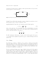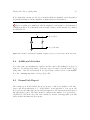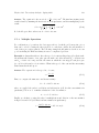
1
Physics 124 Lab Manual
Amherst College
Spring 2012
Contents
General Instructions
6
Laboratory Syllabus
11
1 Optics I: Ray Optics
12
1.1
Questions for Lab Preparation . . . . . . . . . . . . . . . . . . . . . . . . .
12
1.2
Introduction . . . . . . . . . . . . . . . . . . . . . . . . . . . . . . . . . . . .
12
1.3
Experiment 1: Snell’s Law . . . . . . . . . . . . . . . . . . . . . . . . . . . .
13
1.4
Experiment 2: Thin Lenses . . . . . . . . . . . . . . . . . . . . . . . . . . .
14
1.5
Additional Activities . . . . . . . . . . . . . . . . . . . . . . . . . . . . . . .
15
2 Optics II: Wave Optics
17
2.1
Questions for Lab Preparation . . . . . . . . . . . . . . . . . . . . . . . . .
17
2.2
Introduction . . . . . . . . . . . . . . . . . . . . . . . . . . . . . . . . . . . .
17
2.3
Experiment 1: Young’s Double Slit . . . . . . . . . . . . . . . . . . . . . . .
20
2.4
Experiment 2: Polarization . . . . . . . . . . . . . . . . . . . . . . . . . . .
22
2.5
Additional Activities . . . . . . . . . . . . . . . . . . . . . . . . . . . . . . .
22
2.6
Formal Lab Report . . . . . . . . . . . . . . . . . . . . . . . . . . . . . . . .
24
1
2
3 Introduction I: Electrostatics
25
3.1
Introduction . . . . . . . . . . . . . . . . . . . . . . . . . . . . . . . . . . . .
25
3.2
Experiment 1: Tape Electrometer . . . . . . . . . . . . . . . . . . . . . . . .
25
3.3
Experiment 2: Versorium . . . . . . . . . . . . . . . . . . . . . . . . . . . .
26
3.4
Experiment 3: Electrophorus . . . . . . . . . . . . . . . . . . . . . . . . . .
27
3.5
Experiment 4: Wimshurst Machines . . . . . . . . . . . . . . . . . . . . . .
27
3.6
Experiment 5: Van de Graaf Generator . . . . . . . . . . . . . . . . . . . .
28
3.7
Experiment 6: Kelvin Water Dropper . . . . . . . . . . . . . . . . . . . . .
28
4 Introduction II: Equipment
29
4.1
Questions for Lab Preparation . . . . . . . . . . . . . . . . . . . . . . . . .
29
4.2
Introduction . . . . . . . . . . . . . . . . . . . . . . . . . . . . . . . . . . . .
29
4.3
Experiment 1: Voltmeter - Constant Voltages . . . . . . . . . . . . . . . . .
30
4.4
Experiment 2: Voltmeter - Time-varying voltages . . . . . . . . . . . . . . .
33
4.5
Experiment 3: Oscilloscope . . . . . . . . . . . . . . . . . . . . . . . . . . .
33
4.6
Experiment 4: Function Generator . . . . . . . . . . . . . . . . . . . . . . .
38
4.7
Experiment 5: A Warning about Grounds . . . . . . . . . . . . . . . . . . .
40
4.8
Experiment 6: Mystery Signals . . . . . . . . . . . . . . . . . . . . . . . . .
41
4.9
Additional Activities . . . . . . . . . . . . . . . . . . . . . . . . . . . . . . .
41
5 Resistors I
43
5.1
Questions for Lab Preparation . . . . . . . . . . . . . . . . . . . . . . . . .
43
5.2
Introduction . . . . . . . . . . . . . . . . . . . . . . . . . . . . . . . . . . . .
43
5.3
Definitions . . . . . . . . . . . . . . . . . . . . . . . . . . . . . . . . . . . . .
44
3
5.4
Schematic Diagrams . . . . . . . . . . . . . . . . . . . . . . . . . . . . . . .
45
5.5
Equipment . . . . . . . . . . . . . . . . . . . . . . . . . . . . . . . . . . . .
50
5.6
Experiment 1: First Circuit . . . . . . . . . . . . . . . . . . . . . . . . . . .
53
5.7
Experiment 2: Kirchhoff’s Rules . . . . . . . . . . . . . . . . . . . . . . . .
54
5.8
Experiment 3: Ohm’s Law . . . . . . . . . . . . . . . . . . . . . . . . . . . .
56
5.9
Experiment 4: Ohmmeter . . . . . . . . . . . . . . . . . . . . . . . . . . . .
58
5.10 Experiment 5: Correcting Meter Imperfections . . . . . . . . . . . . . . . .
59
5.11 Additional Activities . . . . . . . . . . . . . . . . . . . . . . . . . . . . . . .
60
6 Resistors II
64
6.1
Questions for Lab Preparation . . . . . . . . . . . . . . . . . . . . . . . . .
64
6.2
Introduction . . . . . . . . . . . . . . . . . . . . . . . . . . . . . . . . . . . .
64
6.3
Experiment 1: Ohmic vs. Dynamic Resistance
. . . . . . . . . . . . . . . .
65
6.4
Experiment 2: Impedance . . . . . . . . . . . . . . . . . . . . . . . . . . . .
65
6.5
Additional Activities . . . . . . . . . . . . . . . . . . . . . . . . . . . . . . .
70
6.6
Formal Lab Report . . . . . . . . . . . . . . . . . . . . . . . . . . . . . . . .
70
7 Capacitors I
71
7.1
Questions for Lab Preparation . . . . . . . . . . . . . . . . . . . . . . . . .
71
7.2
Introduction . . . . . . . . . . . . . . . . . . . . . . . . . . . . . . . . . . . .
71
7.3
Experiment 1: Voltmeter Input Impedance . . . . . . . . . . . . . . . . . .
72
7.4
Experiment 2: Function Generator Output Impedance . . . . . . . . . . . .
72
7.5
Experiment 3: Resistor-Capacitor Circuit - Step change in Voltage . . . . .
73
7.6
Additional Activities . . . . . . . . . . . . . . . . . . . . . . . . . . . . . . .
78
4
8 Capacitors II
79
8.1
Questions for Lab Preparation . . . . . . . . . . . . . . . . . . . . . . . . .
79
8.2
Introduction . . . . . . . . . . . . . . . . . . . . . . . . . . . . . . . . . . . .
79
8.3
Experiment 1: Resistor-Capacitor Circuit - Sinusoidal Response . . . . . . .
79
8.4
Additional Activities . . . . . . . . . . . . . . . . . . . . . . . . . . . . . . .
85
8.5
Formal Lab Report . . . . . . . . . . . . . . . . . . . . . . . . . . . . . . . .
85
9 Inductors I
86
9.1
Questions for Lab Preparation . . . . . . . . . . . . . . . . . . . . . . . . .
86
9.2
Introduction . . . . . . . . . . . . . . . . . . . . . . . . . . . . . . . . . . . .
86
9.3
Experiment 1: RL Circuit - Step Response . . . . . . . . . . . . . . . . . .
87
9.4
Experiment 2: RL Circuit - Sinusoidal Response . . . . . . . . . . . . . . .
90
9.5
Experiment 3: RLC Meter . . . . . . . . . . . . . . . . . . . . . . . . . . .
92
9.6
Additional Activities . . . . . . . . . . . . . . . . . . . . . . . . . . . . . . .
92
10 Inductors II
94
10.1 Questions for Lab Preparation . . . . . . . . . . . . . . . . . . . . . . . . .
94
10.2 Introduction . . . . . . . . . . . . . . . . . . . . . . . . . . . . . . . . . . . .
94
10.3 Experiment 1: RLC Circuit . . . . . . . . . . . . . . . . . . . . . . . . . . .
99
10.4 Formal Lab Report . . . . . . . . . . . . . . . . . . . . . . . . . . . . . . . .
102
A Keeping a Lab Notebook
104
B Formal Lab Report
108
C Uncertainty Analysis
112
5
C.1 Expressing Experimental Uncertainties . . . . . . . . . . . . . . . . . . . . .
113
C.2 Determining Experimental Uncertainties . . . . . . . . . . . . . . . . . . . .
114
C.3 Propagation of Uncertainties . . . . . . . . . . . . . . . . . . . . . . . . . .
115
C.4 Assessing Uncertainties and Deviations
from Expected Results . . . . . . . . . . . . . . . . . . . . . . . . . . . . . .
118
C.5 The User’s Guide to Uncertainties . . . . . . . . . . . . . . . . . . . . . . .
121
D Complex Numbers
123
Bibliography
126
General Instructions
The laboratory sessions of Physics 124 are designed to help you become more familiar
with fundamental physical concepts by actually carrying out quantitative measurements of
physical phenomena. The labs are designed to help you develop several basic skills and
several “higher-level” skills. The basic skills include the following:
1. Being able to relate abstract concepts to observable quantities. For example, knowing how one determines the electrical resistance of a device from easily measured
quantities. This skill includes the ability to estimate and measure important physical
quantities at various levels of precision.
2. Knowing how to use common equipment found in professional research laboratories,
such as voltmeters, oscilloscopes, signal generators, and prototyping breadboards.
3. Knowing and applying some generally useful measurement techniques for improving
the reliability and precision of measurements, such as using repeated measurements
and applying comparison methods.
4. Being able to estimate the experimental uncertainties in quantities obtained from
measurements.
The higher-level skills include the following:
1. Planning and preparing for measurements.
2. Executing and checking measurements intelligently.
3. Analyzing the results of measurements both numerically and graphically. This skill
includes assessing experimental uncertainties and deviations from expected results.
4. Being able to describe, talk about, and write about physical measurements.
The laboratory work can be divided into three parts: preparation, execution, and analysis. The preparation, of course, must be done before you come to your laboratory
Physics 124 · General Instructions · Spring 2012
7
session. The execution and analysis (for the most part) will be done during the three-hour
laboratory sessions. Some suggestions for performing these three parts successfully are given
below. Please also refer to Appendix A, Keeping a Laboratory Notebook, since good
note-taking will be essential in all phases of the lab.
Preparation (Before Lab)
1. Read the laboratory instructions carefully. Make sure that you understand what the
ultimate goal of the experiment is.
2. Review relevant concepts in the text and in your lecture notes.
3. Outline the measurements to be made.
4. Understand how one goes from the measured quantities to the desired results.
5. Organize tables for recording data and the equations needed to relate measured quantities to the desired results.
6. Complete any written assignments related to these preparations in advance of the
laboratory meeting.
Execution (During Lab)
1. LABORATORY NOTEBOOK: A laboratory notebook is one of the most important
elements of executing the experiment. You will need to keep a step-by-step record
of what you’ve done, how you’ve done it, and in what order. Obtain an inexpensive,
permanently bound notebook (spiral notebooks and binders are not acceptable) for
recording your laboratory data, your analysis of the data, and the conclusions you
draw from the measured results along with any other relevant comments.
BE NEAT. The notebook is an informal record of your work, but it must be sufficiently neat and well-organized so that both you and the instructor can understand
exactly what you have done. It is also advantageous for your own professional development that you form the habit of keeping notes on your experimental work —
notes of sufficient clarity that you can understand them at a later time. Developing
good lab notebook technique requires consistent effort and discipline, skills that will
be of great value in any professional career. If you become a research scientist, you
will often (while writing reports or planning a new experiment) find yourself referring
back to work you have done months or even years before; it is essential that your notes
be sufficiently complete and unambiguous that you can understand exactly what you
did then. In keeping a laboratory notebook, it is better to err on the side of verbosity
and redundancy than to leave out possibly important details.
Physics 124 · General Instructions · Spring 2012
8
NEVER ERASE data or calculations from your notebook. If you have a good
reason to suspect some data (for example, you forgot to turn on a power supply) or
a calculation (you entered the wrong numbers in your calculator), simply draw one
line through the data or calculation you wish to ignore and write a comment
in the margin. It is surprising how often “wrong” data sets turn out to be useful after
all.
USE PEN to record all of your data so that you will not fall prey to the temptation
to erase. There will not be any pencils allowed in the lab.
WRITE ON ONE SIDE of the page only. This allows for a blank space to insert
graphs or new data and helps with neatness.
As mentioned above, Appendix A gives instructions on how to keep a good lab notebook. You will be expected to adhere to these guidelines throughout the semester.
2. DATA: Naturally, you will need to pay attention to your data-taking technique.
Throughout the semester, you will be learning how to use various types of measurement equipment, sometimes crude and sometimes sophisticated. In all cases, the
quality of your data will depend on your understanding of when and how to use the
equipment. It is always more important to put care and thought into the setup for
a measurement than it is to attain a (sometimes deceptively) high level of accuracy
from a meter. Sure, you will want to optimize the accuracy, but only when you’re sure
you’re making the right measurement. For example, if you build a circuit incorrectly,
it doesn’t matter how many digits you get out of a voltage reading. If the circuit is
wired wrong, the results will be wrong, too. So take care to think first, and always
critically assess your measurements as you go along to see if they make sense.
3. QUICK DATA ASSESSMENT: After taking a piece of data ask yourself, “Does the
data make sense?” Do a quick “back-of-the-envelope” calculation to see if it does. If
it doesn’t make sure you know why. Don’t fall into the trap of taking tons of data and
analyzing it at the end. You need to make sure things are making sense as you go.
This will prevent you from taking a whole data set with an improperly wired resistor.
Analysis (During Lab)
1. GRAPHS AND CALCULATIONS: In addition to the ongoing analysis you conduct
during data-taking, you will be expected to perform a more thorough analysis for
each experiment. Most importantly, you will be asked to obtain meaningful physical
results from the measurements. Often, though not always, this will be done in the
context of graphical analysis. That is, usually you will fit a curve, most often a line,
to the graph and extract the fit parameters, such as the slope. Of secondary (though
not insignificant) importance is the need for you to specify some limits of accuracy
about your results. This phase of the operation is often mistakenly referred to as
“Error Analysis.” In fact, the expression for determining the range of uncertainty in
a particular measurement is, appropriately, “Uncertainty Analysis.” Below are some
guidelines to help with this process.
Physics 124 · General Instructions · Spring 2012
9
2. UNCERTAINTIES: The stated results of any measurement are incomplete unless accompanied by the uncertainty in the measured quantity. By the uncertainty, we mean
simply: How much greater, or smaller, than the stated value could the measured quantity have been before you could tell the difference with your measuring instruments?
If, for instance, you measure the distance between two marks as 2.85 cm, and judge
that you can estimate halves of mm (the finest gradations on your meter stick), you
should report your results as 2.85 ± 0.05 cm. More details on uncertainties are given
in Appendix C.
An important (if not the most important) part of the analysis of an experiment is
an assessment of the agreement between the actual results of the experiment and
the expected results of the experiment. The expected results might be based on
theoretical calculations or the results obtained by other experiments. If you have
correctly determined the experimental uncertainty for your results, you should expect
your results to agree with the theoretical or previously determined results within the
combined uncertainties. If your results do not agree with the expected results, you
must determine why. Several common possibilities are the following:
(a) You underestimated the experimental uncertainties;
(b) There is an undetected “systematic error” in your measurement;
(c) The theoretical calculation is in error;
(d) The previous measurements are in error; or
(e) Some combination of the above.
Sometimes these deviations are “real” and indicate that something interesting has
been discovered. In most cases (unfortunately) the explanation of the deviation is
rather mundane (but nevertheless important). Remember that small deviations from
expected results have led to several Nobel prizes.
Analysis (After Lab)
You will prepare four formal lab reports this semester. One for each of the major laboratory
topics that we will cover: optics, resistors, capacitors, and inductors. For formal reports,
you are to prepare a somewhat longer, written account of your experimental work. These
reports should include a complete description of the experiment and its results. They should
be compiled in a word processor and turned in according to the schedule in the syllabus.
You should pay special attention to the clarity and conciseness of your writing. In fact, if
we find that your report would benefit from rewriting, we may ask you to submit a revised
version of the report before a grade is assigned to the report. Guidelines for preparation of
formal lab reports are included in Appendix B.
Physics 124 · General Instructions · Spring 2012
10
Grading
You must complete all of the labs to pass Physics 124. If you have to miss a lab because
of illness, family difficulties, or other legitimate reasons, please let me know in advance
(whenever possible) so we can arrange for a make-up time.
You will receive a grade for each of the writeups in your lab notebook and each formal
report according to the grading policies listed on the syllabus.
Intellectual Responsibility
Discussion and cooperation between lab partners is strongly encouraged an, indeed, often
essential during the lab sessions. However, each student must keep a separate record of
the data and must do all calculations independently. In addition, laboratory partners are
expected to share equally in the collection of data.
The use of any data or calculations other than one’s own, or the modeling of discussion or
analysis after that found in another student’s report, is considered a violation of the Honor
Code. We wish to emphasize that intellectual responsibility in lab work extends beyond
simply not copying someone else’s work to include the notion of scientific integrity, i.e.,
“respect for the data.” By this we mean you should not alter, “fudge,” or make up data
just to have your results agree with some predetermined notions. Analysis of the data may
occasionally cause you to question the validity of those data. It is always best to admit
that your results do not turn out the way you had anticipated and to try to understand
what went wrong. You should NEVER ERASE data that appear to be wrong. In fact, it’s
better for you to use ink for lab notebooks anyway. It is perfectly legitimate to state that
you are going to ignore some data in your final analysis if you have a justifiable reason to
suspect a particular observation or calculation.
Finally
In the midst of these bewildering “ground rules” it is important to keep in mind that the
laboratory exercises can be both challenging and rewarding. As with any fundamentally
collaborative effort, the amount of fun you end up having during these sessions will depend
to some degree on the openness, humor, and good will that you bring with you. Enjoy!
Physics 124 · Laboratory Syllabus · Spring 2012
11
Laboratory Syllabus
We will meet Wednesdays from 2–5pm for the laboratory. This semester we will begin and
end promptly at the appointed hours. (Please plan to spend the entire period in class.) All
of the labs must be completed to receive a passing grade.
For the four sessions marked with a F, below, a formal report will be required.
Date
Jan. 25
Feb. 1
Feb. 8
Feb. 15
Feb. 22
Feb. 29
Mar. 7
Mar. 14
Mar. 21
Mar. 28
Apr. 4
Apr. 11
Apr. 18
Apr. 25
May 2
Lab
(No Lab)
Optics I: Ray Optics
Optics II: Wave Optics F
(Exam)
Introduction I: Electrostatics
Introduction II: Equipment
Resistors I
Resistors II F
(Spring Break)
(Exam)
Capacitors I
Capacitors II F
Inductors I
Inductors II F
(No lab)
Reading
Lab 1
Optics I: Ray Optics
1.1
Questions for Lab Preparation
1. Explain what the critical angle, θC , is.
2. There is an unlabeled lens on the table. You need to find its focal length. Using only
the room lights overhead, the lens, and the table how might you estimate the focal
length?
3. What does an image distance of infinity mean? Is the image really at infinity? Almost
all microscope objectives have an image distance of infinity, why?
1.2
Introduction
One way to model the behavior of light is to think of it as a simple ray. A single ray (an
arrow) just represents the direction the light is propagating. Sometimes we can model light
as just a single ray; for instance, a laser pointer traveling through the air and reaching a
projection screen might be modeled as a single ray. Other times we might model light as
two rays or multiple rays. A light bulb may be modelled as multiple rays since it sends
light out in all directions. Modeling light as two or more rays is also useful when modeling
a laser beam incident on a lens. Even though all the rays are initially propagating in the
same direction the curvature of the lens will refract each ray differently. Knowing where
multiple rays end up, not just one ray, tells you more about the properties of the lens.
Sometimes this simple model is too crude, and we will need to model light as a wave or
a particle. However, the ray model of light is incredibly useful when discussing the laws
of reflection and refraction. In this lab, you will investigate the fundamental relationship
Physics 124 · Lab 1 · Spring 2012
13
90◦
laser beam
air
180◦
θ1
θ2
0◦
gelatin
270◦
Figure 1.1.
between incident and refracted light beams. This is the foundation for building more complicated refractive optics such as lenses and optical instruments. Thus, our treatment of
light as a ray will suffice.
1.3
Experiment 1: Snell’s Law
Snell’s Law states that for light incident at a normal angle θ1 on a smooth interface between
two materials of indices of refraction n1 and n2 , the normal angle θ2 of the refracted light
is related to θ1 by
n1 sin θ1 = n2 sin θ2 .
(1.1)
! Place the D-shaped semicircle of gelatin (“stiff water”) within its plastic holder on top
of the polar ruled acetate sheet. Place the gelatin in such a way that the straight side is
aligned with the 90-270 degree line on the paper, and so that the midpoint of the straight
side sits at the center of the polar grid, as shown in Fig. 1.1. Set the laser so that the
light beam shines through the circular “wall” of the gelatin and exits at the midpoint of
the straight side (see Fig. 1.1). The light will enter the gelatin normal to its surface. You
will need to set the height of the laser (by propping it up on a book or some such object)
so that you can see the beam as it enters and exits the gelatin. Rotate the laser beam until
you discover the angle θC for total internal reflection for water. (Make sure that the beam
is exiting at the midpoint of the straight side.)
Physics 124 · Lab 1 · Spring 2012
14
? What is the critical angle? Use it to determine the index of refraction of water from the
relation sin θC = 1/nW .
! Record the incident and refracted beam angles, θ1 and θ2 , respectively, starting with
θ1 = 0 and increasing θ1 in 5◦ increments for as many data points as you can. Make sure
to read the θ2 values relative to the normal, i.e., relative to the 180◦ line. Determine the
index of refraction of the water by using IGOR to fit to the functional form
θ2 = sin−1 (A sin θ1 ) .
(1.2)
? Compare the two values that you measure. Are they the same?
1.4
Experiment 2: Thin Lenses
If a point source is a distance s from a “thin” lens, then light diverging from the source will
be refracted by the lens and will converge at a distance s0 from the lens (see Fig. 1.2). Here
s and s0 are related to the focal length, f , of the lens by the Gaussian lens equation:
1
1
1
+ 0 = ,
s s
f
(1.3)
where f is a length characteristic of the particular lens used. Its value depends upon the
radii of curvature of the spherical surfaces of the lens and on the material of which the lens
is made. (Note: in the drawing we assume s > f .)
f
f
source
image
+
s
+
s0
Figure 1.2.
If a screen were placed at s0 , then a bright spot would appear on the screen. If, instead of
a point source, we had an extended source a distance s from the lens, then a focused image
of this extended source would appear on the screen at a position s0 . Indeed, if we placed
a photographic plate instead of a screen at this position, we would have the makings of a
camera.
Physics 124 · Lab 1 · Spring 2012
15
In this experiment, you will test the validity of equation 1.3. There are two (or so) setups
for each minilab, so you will need to circulate from station to station.
! If an object is very far from the lens (s f ), then 1/s 1/f . In this case we expect
from the equation that the distant object will be focused at a distance s0 = f . To get a
crude idea of the focal length of the lens you are using, find some very distant bright object
(e.g., a mountain or a tree) and measure the distance from the lens to a point where the
light is focused. Be sure to include with your measurement an estimate of the uncertainty
associated with f .
! You have been provided with a light source, a screen, an optical bench, and a meter
stick. Using these, set up an experiment to test the validity of Eq. 1.3. Plot your data in
such a way that, if the theory is correct, you ought to obtain a straight line graph from
which you can obtain the focal length of the lens. Again, be sure to estimate the uncertainty
in your measurement. Does your value deduced here agree with that obtained in Part I?
While making these measurements, observe the characteristics of the image produced. Is
the image larger or smaller than the original object? Is the image inverted?
! Repeat the last exercise with a different lens that has a different curvature, and hence
focal length. Which lens has the larger f ? For which lens are the surfaces more curved (i.e.,
depart further from being planes)? Which lens is “stronger”?
! Take one of the “negative” lenses. Estimate its focal length by using the method of
parallax (or some other method) to ascertain the position of virtual images produced by
the lens. We use parallax all of the time to determine which of two objects is closer than
the other. You will want to apply the method of parallax to the image of a distant object
viewed through the lens and a (closer) object viewed outside of the lens.
1.5
1.5.1
Additional Activities
Intensity of Light
Here you will explore the phenomenon that light from a point source propagates outward
uniformly in all directions about the source. Without any optical interference, such as lenses,
mirrors, or interfaces, light will propagate outward from a point source in a straight line,
filling a spherically symmetric volume. Because the total energy per unit time produced
by the source is constant, the intensity (energy per unit area per unit time) must fall off
with distance from the source. In fact, since the area of a spherical shell surrounding the
source increases as the square of the distance r from the source, the intensity I is expected
to exhibit “inverse square law behavior” when measured as a function of r.
On an optical bench, align a light bulb 10 cm in front of a photo sensor (light detector),
Physics 124 · Lab 1 · Spring 2012
16
filter
r
light
bulb
detector
Figure 1.3.
as shown in Fig. 1.3. The detector is designed so that it will give an output voltage
proportional to the intensity of the light hitting the sensor so long as the voltage is less
than 300 mV. That is, for low intensities, the detector responds linearly to the intensity.
We will want to conduct this experiment in the linear region of the detector. To make sure
this happens, place a holder that contains a collection of light absorbers (these are actually
just partially darkened overhead transparencies cut into 2 inch squares) between the bulb
and the detector so that the output reading is close to but not more than 300 mV. The
absorber (filter) allows only a fraction of the light to penetrate through it. It should be
positioned very close to the bulb.
! Examine qualitatively what happens to the intensity when the source-detector spacing
r is gradually increased. Take quantitative measurements of the detector output voltage V
vs. r for at least 10 readings between 10 cm and 80 cm. These readings do not need to be
evenly spaced.
? What is the background voltage or the intensity when the light bulb is off? Is it necessary
to subtract the background voltage? It it is, do this now.
! First, make a plot of V (with background subtracted if necessary) vs. r. Fit the data
in IGOR to a line, an inverse square law, and an exponential decay. What is the best fit?
Does this make sense? Can you identify reasons for any discrepancies by looking carefully
at your plot?
Lab 2
Optics II: Wave Optics
2.1
Questions for Lab Preparation
1. Is light a transverse or longitudinal wave? What is sound? Light has a polarization
and exhibits interference. Does sound have these properties? Why or why not?
2. In Young’s time there were not lasers, only white light. Could you do Young’s Double
Slit experiment that is described in this manual with white light? Why or why not?
3. What is the reason the lab manual gives for why polarized sun glasses are useful?
What is the actual reason? (Hint: It has to do with glare.)
2.2
Introduction
In our last laboratory on ray optics we treated light as if it were composed of rays. While this
approximation is usually adequate for objects which are large compared to the wavelength
of light, it is not adequate for describing the interaction of light with small objects. In this
case, it is necessary to consider light as an electromagnetic wave.
2.2.1
Light as an Electromagnetic Wave
At this point in the semester we have not discussed fields let alone the electric field, magnetic field, or electromagnetic field. However, many of you have probably heard the terms
before. For the purposes of this lab we need to know that light acts as a transverse wave. In
a transverse wave the oscillation of the wave occurs perpendicular to the direction of propagation. Transverse waves that you should be familiar with from introductory mechanics
Physics 124 · Lab 2 · Spring 2012
18
include water waves and waves on a string. Compare transverse waves to longitudinal waves.
In a longitudinal wave the oscillation and the propagation of the wave occur in the same
dimension. A good example of a longitudinal wave is sound. A sound wave changes the
local density of the medium as it propagates through, appearing as a series of compressions
and rarefactions.
If we want to mathematically define a transverse wave we might write down the equation for
the amplitude, A, of the oscillation as a function of both time, t, and propagation distance,
x. This might look something like:
h x
i
A = A0 cos 2π
− ft .
λ
(2.1)
Here A0 is the maximum amplitude of the wave, f is the frequency of the wave, and λ is
the wavelength of the wave. Remember from introductory mechanics that if we know f
and λ we also know the speed of the wave. This equation could be used for a water wave,
a wave on a string, or light. However, in the case of light we usually define the electric
field, E, as the thing that oscillates (even though the magnetic field oscillates too, in a
plane perpendicular to both the electric field and the direction of propagation). So instead
of using A for amplitude let’s just use E for the electric field. In your head you can just
replace all the E’s with A’s. Additionally, if the manual talks about an electromagnetic
wave you can just replace this with the word light.
Therefore, the magnitude of the electric field associated with a beam of light propagating
in the x-direction may be written as
h x
i
E = E0 cos 2π
− ft .
(2.2)
λ
This describes a “traveling” wave with an amplitude E0 and a velocity equal to f λ, where
f is the frequency of the light and λ is the light’s wavelength.
Note: The intensity of an electromagnetic wave is proportional to the total electric field
squared (E 2 ).
2.2.2
Interference
Because light is a wave, it may exhibit the property of interference. Consider what would
happen if two electromagnetic waves were traveling in the same direction but with their
phases shifted by 180◦ . That is, we let one wave have its maximum just as the other is at
its minimum. The total electric field is just the sum of the electric fields associated with
each beam, in accordance with the principle of superposition.
Physics 124 · Lab 2 · Spring 2012
19
So
E = E1 + E2
i
h x
i
h x
− f t − E0 cos 2π
− ft
= E0 cos 2π
λ
λ
= 0.
(2.3)
(2.4)
(2.5)
The field associated with the second beam will exactly cancel the first and there is no net
field. Since there is no field, there is no intensity, and hence we would see no light. This
phenomenon is called total destructive interference. Alternatively, we could imagine two
electromagnetic waves having the same amplitude and phase. Then the total field would
simply double:
h x
i
E = E1 + E2 = 2E0 cos 2π
− ft .
(2.6)
λ
Because the intensity of light is proportional to the square of the electric field the intensity
would quadruple. This phenomenon is called “constructive” interference.
2.2.3
Diffraction
Diffraction and interference seem to go hand and hand in introductory texts. Sometimes
this classification blurs the definition of diffraction in student’s minds. Diffraction is just
the spreading of a wave with a fixed beam diameter. Typically, the Huygens Construction is
employed to show how this spreading would occur. See Section 34.1 in Ohanian’s ”Physics
for Engineers and Scientists” for more details.
The divergence angle of the beam, θD , mathematically defines how much diffraction or
spreading will occur. The divergence angle for a particular beam with wavelength, λ, and
diameter, D, is given by:
θD =
2λ
.
πD
(2.7)
This shows that as the beam diameter decreases the amount of diffraction increases.
? In the ray optics lab we talked about a lens focusing a beam of light to a point. This
was referred to as the focal point of the lens. Is the focal point real? After learning about
diffraction do you think we can focus a beam to an infinitesimal point?
Physics 124 · Lab 2 · Spring 2012
2.3
20
Experiment 1: Young’s Double Slit
Today we would like to observe these “wavelike” properties of light. To do this we will
do Young’s double-slit experiment. In this experiment an electromagnetic wave is incident
upon two narrow apertures. We let the separation between the two apertures be d. The
electromagnetic wave will exit the two slits with approximately the same amplitude and
phase. If we place a screen some distance D away from our two slits, the electromagnetic
waves propagating from the two slits will combine to illuminate the screen (see Fig. 2.1).
y
θ
d
∆L = d sin θ
D
Figure 2.1.
The distance traveled by the wave from slit 2 to the screen is longer than that traveled by
the wave from slit 1. The difference in the path lengths is approximately equal to
∆L = d sin θ
(2.8)
where θ is the angle shown in the figure.
Now, if y D, then θ is small and sin θ = y/D. The difference in travel distances is then
∆L = yd/D.
If this path difference is equal to nλ, where n is an integer, then there will be a constructive
interference and we will see a bright spot on the screen. Thus the positions of the bright
spots will be at positions yn given by
nλ =
yn d
D
or
yn =
nDλ
.
d
(2.9)
The separation between two successive bright spots will then be given by
∆y = yn+1 − yn =
Dλ
.
d
(2.10)
Similarly, for points where the path difference ∆L creates a phase shift of 180◦ there will
be destructive interference and no light will be observed. These points of destructive interference will be halfway between the bright maxima. They will also be separated by a
Physics 124 · Lab 2 · Spring 2012
21
distance
∆y =
Dλ
.
d
(2.11)
If we measure ∆y, d, and D, we can in principle measure the wavelength of the incident
light.
In order to perform this experiment a helium-neon (He-Ne) laser will be used. Lasers create
light that propagates only in a particular direction and is monochromatic (i.e., it has only
one frequency or wavelength). You will determine the wavelength of this laser light from
your double slit interference experiment.
You have been provided with a photographic plate that has a column of double slits. For
our lab today we will use at least two of these double slits. For ease of measurement we
recommend the second- and third-widest double slit pairs on your film; note that in the
“series” of double-slits, the narrowest is actually only a single slit.
! For at least these two slit pairs measure the distance d between the slits as follows: put
the whole photographic plate on an overhead projector to magnify the image. Measure the
slit separation the image as well as the width of the whole photographic plate and its image
at the horizontal line through the slits whose width is being measured. Because the slits
have a finite width, you may want to measure edge to edge and average your results for left
edges and right edges to get a value for d. Repeat this measurement enough times so that
you have a good idea of the uncertainty in d.
! Shine your laser beam onto one of the double slits that you have measured. Place a
screen at large distance D (at least a couple of meters) away from the double slit. You
should observe several points of constructive and destructive interference. To get maximum
sensitivity here it is important that the ambient light be dim. Measure the distance between
successive minima. To get the best precision in this measurement, measure the interval over
several successive minima and divide by the number of intervals. From your measurement,
determine the wavelength of the He-Ne laser. Be sure to include an estimate of the uncertainty in your measurement. (CAUTION: You will see successive brightening and dimming
of the maxima as you move away from the center. This is an interference effect associated
with the finite slit widths. Do not confuse it with the double-slit interference pattern.)
! Repeat the last exercise for your second slit pair. Obtain a second value for the He-Ne
wavelength along with the uncertainty.
? Are your two answers the same? Explain any differences. Which do you have more
confidence in? Which has greater separation between maxima? What do you think you
would see for d = 2 m?
Physics 124 · Lab 2 · Spring 2012
2.4
22
Experiment 2: Polarization
Certain materials (such as the polymers in our polarizers) have the ability to respond to an
incident electric field by absorbing all of the light that has an electric field aligned with the
polymers, and re-radiating the light that does not. We can think of light shining directly
on a polarizer as having two components of electric field, one aligned with the polymers,
and one perpendicular to that direction. (The third dimension, perpendicular to the plane
of the polarizer, doesn’t matter and need not be considered here.) The light that makes it
through the polarizer is the perpendicular component. We say that the transmitted light is
polarized because it comes out having an E-field in a single, well-defined direction (that we
might mark on the polarizer with an arrow), regardless of what its E-field orientation was
to begin with. This is good news for those of us who wear sunglasses since the polarizer
acts somewhat as an E-field filter and cuts the transmitted light intensity way down.
? Why does the third dimension, perpendicular to the plane of the polarizer, not matter?
To get polarized light in the first place, we can pass unpolarized light (light with many
random orientations of the E-field vector, such as the light from our bulb) through one
polarizer. It turns out that in that case, half of the incident light intensity makes it through.
If you shine that polarized light onto a second polarizer, the polarization of the output light
is determined by the second polarizer, as discussed above. But the intensity of that light
depends on the relative polarization angles of the polarizers. Malus’s Law describes the
overall output intensity as a function of the angle θ between the alignment axes of the two
polarizers. In fact, Malus’s law says that the output intensity (out of the second polarizer)
and the input intensity (out of the first polarizer) are related by the factor cos2 θ. Why
does this make sense?
! Get a qualitative feel for the effect of crossed polarizers by looking through a stack of
two polarizers and rotating one relative to the other. You’ll probably need to do this in a
well-lit room. What do you notice about the light intensity? Do your observations make
sense in light of the above discussion?
2.5
Additional Activities
2.5.1
Single Slit Experiment
In your double slit experiment cover one of your slits so that light is only passing through a
single slit. What happens to the pattern you observe on the screen? Measure the distance
to the first minima. Does this measurement make sense? Use the discussion in section 35.5
of Ohanian’s ”Physics for Scientists and Engineers” to help you.
Physics 124 · Lab 2 · Spring 2012
23
laser
fixed polarizer
second polarizer
(rotates)
detector
Figure 2.2.
2.5.2
Laser Polarization
Is the He-Ne laser light polarized? Using the polarizer, make up an experiment to test this
question. What do you find?
2.5.3
Intensity due to Angle between Polarizers
On the optical bench set up on the laser, a polarizer holder, a rotatable polarizer, and
the detector, as shown in Fig. 2.2. The first polarizer should be aligned so as to pass the
inherently polarized laser light beam. Direct this light through the second polarizer and
adjust its orientation so the transmitted intensity is a maximum. The transmission axes of
the two polarizers are now parallel to one another. Adjust the distance between the second
polarizer and the detector so that the measured intensity does not exceed 300 mV on the
multimeter for this maximum transmitted intensity. Record the measured intensity V every
10◦ by varying the angle between ±90◦ . Because these polarizers are only partially effective,
you may notice a baseline offset. For your data, subtract off this baseline and try a plot of
V vs. cos2 θ. (Beware of software that assumes you’ve entered the data in radians.) What
do you find? Is it consistent with your expectations?
2.5.4
Polarized Sunglasses and Glare
Why do polarized sunglasses remove glare? To figure this out you will need a polarizer
and some glare. Typically, you can find glare on a waxed floor from the overhead lights, so
try the hallway. Look at the glare without the polarizer. Now look at the glare with the
polarizer and rotate the polarizer in your hand while still viewing the glare. What happens?
Do you know how polarized sunglasses work now?
Physics 124 · Lab 2 · Spring 2012
2.6
24
Formal Lab Report
Your lab report should include the measurement of the index of refraction of water from last
week and the measurement of the laser wavelength from this week. Please see the Appendix
on formal lab reports for more details.
Lab 3
Introduction I: Electrostatics
3.1
Introduction
This lab is really a brief menu of experiments designed to get you thinking about the
properties of charged objects and their interactions with other objects, both charged and
uncharged. Since another goal is to become familiar with working in the laboratory, this
is not meant to be particularly strenuous. Have fun! Pay close attention, though, and you
may be surprised by some of the things you see.
3.2
Experiment 1: Tape Electrometer
The equipment for this lab is remarkably simple: two roughly 3 cm long pieces of transparent
tape. Fold a little bit of the ends of the tapes over themselves to make a little “handle” that
won’t stick to things. This will make it easier to pull the tapes apart and off of surfaces.
In addition, you will need some insulators to rub and some materials to rub them with, and
a few assorted objects such as magnets and paper clips. I will provide some of these things;
others you may be carrying around as everyday items in your backpacks.
3.2.1
Preparing the Tapes
On one of the two tapes mark the letter “B” (for Bottom) and, on the other, the letter “T”
(for Top). Stick the two tapes together, sticky-side of tape “T” on the non-sticky side of
tape “B.” Then, holding the tapes by their handles, pull them apart quickly. (Try not to
touch the tapes excessively with your fingers, or anything else.)
Physics 124 · Lab 3 · Spring 2012
26
What do you observe when you bring the tapes near one another? Does the effect change
if you allow the tapes to touch one another? If so, how?
3.2.2
An Electrometer
Prepare the tapes again in the usual way. This time, stick them (carefully!) at
of a table, so that they are sticking out horizontally (i.e., parallel to the table
Try rubbing an insulating (that is, nonmetal) object, such as your plastic pen,
fabric of your clothing. Bring the object up to the tapes (again, be careful not
unintentionally). What is the effect of the object on the tapes?
the edge
surface).
with the
to touch
What happens if you bring instead the rubbing object, e.g., your clothing, near the tapes?
Repeat this experiment several times with different combinations of rubbing and rubbed
objects. What patterns emerge from your data?
If you are careful about handling the tapes you can bring them near charged objects rather
than the other way around. You can try this in the other experiments described below.
3.2.3
Which is Negatively Charged?
We have called the tapes “T” and “B,” which is a perfectly fine convention for their charges.
If we want to communicate with physicists elsewhere, however, we might want to use a
slightly more standard convention and call them “positive” and “negative,” or “+” and
“−.” Ben Franklin chose to call the charge on a glass rod after it had been rubbed with silk
“positive,” and the charge on a rubber rod after rubbing it with fur “negative.” Armed with
this knowledge, can you figure out which of your tapes is positive and which is negative?
Compare with others in the class after making your decision and recording it indelibly in
your lab notebook.
3.3
Experiment 2: Versorium
There are two Versoria you can build: a metal one and a wood one. Explain how each one
works (they are slightly different).
Physics 124 · Lab 3 · Spring 2012
3.4
27
Experiment 3: Electrophorus
Use the electrophorus. Does the metal plate become positively or negatively charged?
3.5
Experiment 4: Wimshurst Machines
BE VERY CAREFUL with the Wimshurst machines — they are quite fragile
and can deliver a momentarily painful electric shock. Turn the crank in the direction indicated by the arrows on the machine chassis. If the belt slips off or the “teeth”
start scraping the wheels contact an instructor. Discharge the machine before attaching or
removing wires.
The Wimshurst machine separates charges by induction. Can you figure out which terminal
is positive and which terminal is negative?
See if you can figure out how the Wimshurst machine works. (Keep it as conceptually
simple as possible.) We’ll discuss it at the end of lab today.
3.5.1
Franklin’s Bells
Consider the following passage, from Walter Isaacson’s recent biography Benjamin Franklin:
An American Life (Simon & Schuster, New York, 2003) p.143:
That September, [Franklin] also erected a [lightning] rod on his own house with
an ingenious device to warn of the approaching of a storm. The rod, which he
described in a letter to [his friend] Collinson, was grounded by a wire connected
to the pump of a well, but he left a six-inch gap in the wire as it passed by his
bedroom door. In the gap were a ball and two bells that would ring when a
storm cloud electrified the rod.
Re-create Franklin’s alarm system, using a suspended pith ball and a pair of plates, one of
which you connect to each terminal of a Wimshurst machine (to represent the Earth and an
electrical storm, respectively). Explain, using appropriate diagrams and descriptions, how
Franklin’s storm-warning system worked. Focus in particular on why the ball alternately
strikes one bell and then the other when a charged storm cloud is overhead.
Physics 124 · Lab 3 · Spring 2012
3.5.2
28
Spinning Structures
If you hook up one of the “spinners” to a terminal of the Wimshurst machine you will find
that it begins to rotate. Why? Does it matter which terminal you attach it to?
3.6
Experiment 5: Van de Graaf Generator
CAUTION: The Van de Graaf can deliver a momentarily painful shock.
Does the dome of the Van de Graaf generator become positively or negatively charged? See
if you can figure out how it works. We’ll discuss it at the end of lab today.
3.7
Experiment 6: Kelvin Water Dropper
Pour water in the top of the Kelvin water dropper. (Try not to get water everywhere.)
Which side becomes positively charged, and which side negatively charged? Does it change
each time you run the experiment? Can you force it to go one way rather than the other?
See if you can figure out how it works. Does anything happen to the water streams when
the machine becomes charged?
Lab 4
Introduction II: Equipment
4.1
Questions for Lab Preparation
1. How are voltage and temperature alike and unalike?
2. Do the voltmeter and oscilloscope measure the same thing?
3. What is a protoboard?
4.2
Introduction
The basic idea of electronics in physics is to take some observable quantity — pressure,
temperature, position, and the like — and convert it into a voltage. This conversion takes
place in a transducer, which might be a microphone, or a kind of thermometer, or strain
sensor. In analog electronics, this voltage is processed by amplification and filtering and
then sent to an output device, which might be an oscilloscope, voltmeter, or loudspeaker.
Input
Transducer
Voltage
Processing
Output
In digital electronics, the voltages are encoded into bits by an analog-to-digital converter,
or ADC. Once digitized, the signal can be processed and stored in a computer, or (possibly)
sent to an analog output device after passing through a digital-to-analog converter (DAC).
Physics 124 · Lab 4 · Spring 2012
30
Figure 4.1. The Fluke 117 digital multimeter.
Input
Transducer
Voltage
Processing
ADC
DAC
Output
Experimental physicists make use of both digital and analog electronics in the laboratory.
We will be focused largely on analog electronics in this class, but most modern instruments
(oscilloscopes, signal generators, and voltmeters) are essentially digital devices.
For now, we can think of voltage (or potential) as simply a quantity that is measured by
a voltmeter. Like temperature, voltage is a scalar field, which means that at every point
in space one can assign a value of the voltage, in volts. Unlike temperature, a voltmeter
can only tell us the difference in the voltage between two different points. This is because
voltage is closely related to energy, and only differences in energy are meaningful.
4.3
Experiment 1: Voltmeter - Constant Voltages
Our first device is the handheld multimeter, which we will be using as a voltmeter today.
Our multimeter is the Fluke 117 (see Fig. 4.1), a fairly general-purpose device that can
measure many electronic quantities.
Physics 124 · Lab 4 · Spring 2012
31
The multimeter has three inputs — one marked A, one marked COM, and the third marked
VΩ · · · . These are at the bottom of the multimeter, and are a kind of connector known as
banana jacks. You will often see the corresponding banana plug that fits into the jack. It is
not entirely clear what the origin of the name is, since neither the plug nor the jack looks
much like a banana.
There are two probe leads that fit into the banana jacks, one of which is red and the other
black. The black lead should be plugged into the COM jack, and the red lead into the
VΩ · · · jack. This is the usual way in which the multimeter is used (we will see in a later
lab how to use the third multimeter jack).
Let’s turn on the multimeter, using the multifunction position knob. Turn it clockwise two
clicks until the selector points towards V. (Do not confuse this setting with the one marked
e The multimeter is now a voltmeter, measuring the voltage difference between the red
V.)
and black leads. Specifically, it is measuring Vred − Vblack , in volts. Unless you are moving
the leads around, or touching them to something in the room, it should read a number that
is close to zero. Keep in mind that positive voltage readings mean that the red lead is at a
higher voltage than the black lead, and that negative voltage readings mean that the black
lead is at a higher voltage than the red lead.
? If you want to read the voltage from a battery do you connect (-) to COM or VΩ · · · ?
At this point the voltmeter can measure voltages that are reasonably constant, i.e., those
that do not change quickly. This is because the voltmeter samples the voltage at regular
intervals (usually a few times a second) and displays the most recent sampled value. If your
voltage is varying rapidly more rapidly than the rate at which the display is updated the
voltmeter cannot give an accurate voltage reading.
! Let’s measure the voltage across a D cell. Chemical reactions that take place within the
cell can add energy to charges that pass through it, raising the voltage on one side of the
cell with respect to the other. As long as the chemical reactions can continue, the voltage
across the cell should be roughly constant — an ideal first test for our voltmeter. The D
cell is a cylinder, with a bump on one of its ends. If you bring the red lead into contact
with the bump, and the black lead into contact with the opposite end, you should be able
to read the voltage across the battery (that is, between the red and black leads).
? What value do you measure? If you reverse the red and black leads, such that you
connect the bumped end of the cell to the black lead, and the flat end to the red lead, what
voltage do you measure?
? Voltage is really a way of talking about the energy of a charge — a higher voltage (for
a positive charge) means a higher energy. In fact, the potential energy U of a charge at a
potential V is U = qV , where q is the charge. In some ways this parallels our understanding
of the gravitational potential energy U = mgh; in terms of mass, rather than charge, what
is the “gravitational voltage”?
Physics 124 · Lab 4 · Spring 2012
32
There are two important concepts that one should keep in mind with any measurement
device in electronics. The first is the concept of precision. Roughly speaking, precision
refers to the number of significant digits that one obtains when measuring some quantity.
The meters we have generally give four digits, with some uncertainty (specified in the user’s
manual) in the last digit. When you measured the voltage across the cell, you could in
principle record all four digits, which means that your least significant digit was a millivolt
(mV), and your precision is ± a few mV.
The second concept is dynamic range. Dynamic range refers to level of precision that is
possible for a given magnitude of the voltage input. When we turn on the multimeter the
dynamic range is automatically set to give you the highest precision measurement possible.
As the magnitude of the input voltage difference increases, however, the ability of the
multimeter to give a highly precise measurement diminishes. For instance, if you were
measuring a potential difference of 8 V, the meter could not give you a precision of ± a
few mV — instead, it would give you a precision of ± a few tens of mV. This is one of
many trade-offs that occur in electronics. We’ll observe this effect directly a little later
on in the lab today; for now, it is important just to have a sense that the precision of a
measurement depends on the magnitude being measured, with higher magnitudes generally
yielding measurements with less precision.
? What is the precision and dynamic range of the measurement you just made?
! Try stacking two D cells together to make a battery1 — and measure the voltage across
the battery. How does your measurement compare to the individual voltages of the cells you
measured earlier? What if you reverse the orientation of one of the cells — what voltage
do you expect, and what do you measure?
With the cells in the “reversed” orientation, your measurement precision is probably about
± a few mV. You can actually do better than this by turning the multifunction knob on
g and then pressing the yellow button
your multimeter one click clockwise, to mV,
just
below the display to make the measurement of constant millivolts. This should give you
one more digit of precision, since your voltage magnitude should be quite small. Record
this value of the voltage across the two cells.
? Keeping the meter on this mV setting, measure the voltage across one of the cells. What
do you measure? This is the dynamic range problem in a nutshell. If you reverse your leads,
can you at least tell which lead is at the higher voltage?
1
In physics, a cell is a single instance of the chemical system that increases the energy of a charge, and
a battery is a collection of cells. In colloquial use, cells and batteries (in the physics sense) are collectively
referred to as batteries.
Physics 124 · Lab 4 · Spring 2012
4.4
33
Experiment 2: Voltmeter - Time-varying voltages
! Not all voltage sources are constant, or nearly so. Indeed, most interesting transducers
generate voltages that can change rapidly, with time scales anywhere from hundreds of
milliseconds to nanoseconds. One such transducer is the simple microphone, a device that
converts sound waves (pressure) into an electrical signal (voltage). Your instructors will
have a few microphones — when you have a chance, try connecting one to your handheld
voltmeter. Do you see any signal? Try talking into the microphone and see if it makes any
difference.
Handheld multimeters can also measure voltages that vary in time, up to a certain rate;
they can then return a sort of average value of the signal.2 If you dial your multimeter to
ACV, or ACmV, you can see what the meter makes of the signal from the microphone when
you talk or hum into it.
Because it is an averaging device, the voltmeter is decidedly imperfect. Often we would
like to know what the voltage is doing as a function of time, not what its average value is
as a function of time. Fortunately there is another device that can do this for us — the
oscilloscope, also known as the physicist’s best friend.
4.5
Experiment 3: Oscilloscope
The oscilloscopes we will use in this class are Tektronix 2001c, which can measure signals
up to about 50 MHz on two input channels. They are general-purpose digital oscilloscopes,
of a kind that has become nearly ubiquitous in research laboratories around the country.
Unlike the digital multimeter, you must plug these oscilloscopes in, although there are now
battery-powered versions that are liberated from the grid.
4.5.1
Getting Started
TURNING IT ON One you have plugged in the oscilloscope, you can turn it on by
pressing the power button on the top of the device. After a few moments of self-testing the
main display might look something like in Fig. 4.2.
The main display graphs the voltage appearing on one (or both) of its input channels as a
function of time. This is a major improvement over the voltage averaging provided by the
multimeter, but with this great power comes great responsibility, as attested by the many
controls on the front panel. In this lab we will spend time on the most essential oscilloscope
2
Technically, this is not quite an average, but the square root of the average of the squares of the
instantaneous signal. The reasons for this will be explored further in a future lab.
Physics 124 · Lab 4 · Spring 2012
34
Figure 4.2. The Tektronix 2001c. (Figure from the Tektronix user manual.)
Figure 4.3. The three inputs to the oscilloscope. (Figure from the Tektronix user manual.)
controls. As you go on in life you will use more and more of the available features, until it
becomes your best friend.
INPUTS There are three inputs to the oscilloscope (see Fig. 4.3). The two signal inputs
are the first two on the left (marked 1 and 2 ); we may talk about the third input
(marked Ext Trig ) later. These inputs are so-called BNC3 connectors. There are special
BNC cables that can be plugged into these connectors; you should try this out now, to get
the sense of how these connectors work. Note that they push on and then turn to make the
solid connection. The voltage difference on a BNC cable is measured between the central
pin and the outer shield. There are also adapters that convert from BNC to banana, in
which case there is a red connector and a black connector. These are mostly similar to the
connectors on the handheld multimeter, with one important exception that we will discuss
in a little while.
? Take a minute to look at the connectors. Suppose you connected a battery to a BNC
cable through the banana/BNC connector such that the (-) end of the battery went to the
3
The letters BNC stand for Bayonet Neill Concelman, after the style of the connector and its inventors.
Physics 124 · Lab 4 · Spring 2012
35
black banana jack and the (+) end went to the red banana jack. At the BNC output would
the (-) end of the battery be the central pin or the outer shield of the BNC connector? Why
do you suppose the BNC cable connection is designed this way?
In this class we are going to make use of the oscilloscope probes, which have a BNC plug
that goes into a BNC jack. You should plug in an oscilloscope probe to channel 1 of the
oscilloscope now. With the probe installed, the voltage difference is measured between the
clip at the end of the probe and the alligator clip that dangles down from the middle of the
probe. This configuration is a little strange, but it is standard and has some advantages in
some circumstances.
For these oscilloscopes, any time you plug in a probe you should connect it to the probe
comp. output, which generates a “square wave” signal. You must clip the alligator lead to
the lower of the two metal connectors, and the probe clip to the upper of the two, being
careful not to “short” the two metal leads together by accidentally clipping across both
leads. Once you’ve clipped the probe on, you should press the Probe Check button just
above it. The oscilloscope will then make sure that its internal settings are appropriate to
the probe you’ve connected.
DISPLAY Now we’re ready to look at the signal on the display. (You may already be
looking at the signal, which is fine, but follow along with these instructions this first time.)
A quick shorthand method for getting the signal on the screen in a nice way is to press the
black AutoSet button in the upper right corner of the front panel. In general you can
usually start with the AutoSet button if you end up having difficulty getting your signal
to display nicely, but you should also recognize that it is something of a “crutch” that you
will ultimately want to abandon as you become more comfortable with the oscilloscope.
After pressing the AutoSet button you should be looking at a square wave signal, something like that shown in Fig. 4.4. The voltage is given on the vertical axis, as a function
of time on the horizontal axis. The screen will have “graticule” (grid) markings on it, and
at the bottom of the screen will be a guide that tells you what the voltage difference is per
division (box) and the time difference per division (box). From this information you can
characterize the signal pretty well.
! Go ahead and characterize the probe comp. signal now. It will be moving rapidly on
the screen and difficult to measure. Estimate its amplitude, average voltage value, and
frequency.
4.5.2
Setting Scales
VERTICAL SCALE You can adjust the sensitivity of the oscilloscope by turning the
Scale knob associated with Channel 1. You can try this now. Note that the oscilloscope
reflects the changes in the vertical scale. There are two Scale knobs, one for each of the
Physics 124 · Lab 4 · Spring 2012
36
Figure 4.4. A typical oscilloscope display, with channel 1 in red and channel 2 in blue. You will have only
the square wave trace at this point. The softmenu selections for channel 1 appear to the right of the voltage
graph.
channels.
You can also move the trace up and down on the screen by adjusting the vertical Position
knob, located above the Scale knob.
If you press the yellow button marked 1 , you will get a menu of options (soft menu) on
the right side of the oscilloscope display. We will discuss some of these options in class. If
you press the button again the trace will disappear. You can make it reappear if you press
it again.
HORIZONTAL SCALE The time interval per division is selected using the Scale knob
in the Horizontal control section of the oscilloscope. You should try this out now. Note
what happens to the display when you turn the Scale knob either direction. Note also that
there is only one Scale knob for the horizontal control — each of the two oscilloscope traces
is plotted against the same time axis. There is also a Horizontal Position knob that moves
the entire trace to the right or left. Try this adjustment, too. If you turn this knob too
far there is a Set to Zero button that will bring the zero of time back to the center of the
display. (We will define the zero of time and the zero of voltage in a little bit.) You can also
bring up a horizontal control softmenu by pressing the Horiz Menu button. We won’t use
that menu so much in this class.
Physics 124 · Lab 4 · Spring 2012
37
The Scale controls, both horizontal and vertical, are used to zoom in on the waveform to
get the best signal. The same kinds of concerns about dynamic range and precision apply
here as do to the multimeter controls.
4.5.3
Setting the Trigger
The final major oscilloscope control system is the Trigger system. The trigger determines
when the oscilloscope causes the voltage traces to update on the screen, and defines the
zero of time. If you have a periodic signal, then it is important that the zero of time line up
from trace to trace; otherwise the traces overlap badly and it will be difficult to see what is
going on with the signal.
There are two principal parts to the trigger: the trigger level (controlled by the Level
knob), and the trigger slope control (found in the Trigger softmenu, after pressing the
Trig Menu button). The trigger level controls the voltage level that triggers the oscilloscope; you can see this on the screen as you move the Level knob around. Whenever the
input voltage is the same as the trigger level, the scope will trigger (update the trace). Of
course, for a typical periodic waveform there might be two points in the waveform at which
the trigger level equals the voltage at the input, one in which the input voltage is decreasing
through the trigger level and one in which the input voltage is increasing through the trigger
level. You can select which of these two “slopes” causes the oscilloscope to trigger through
the softmenu.
There two other aspects of the trigger control that are worth noting, both of which are
available through the trigger softmenu. The first is the trigger type, which can be Auto,
Normal, or Single. The Auto trigger will display the voltage trace even if the trigger level
does not intersect the waveform at all. On the other hand, the Normal trigger setting will
not update the display unless the trigger conditions are met. The Single trigger will take
one trace and then suspend its operation until the Run/Stop button (in the upper right
corner of the front panel) is pressed again to rearm the oscilloscope.
The second aspect is the signal that is used for the trigger. This can be either of the two
input signals, a signal that is provided at the external input BNC connector, or a variety
of other options. You should try out the various trigger settings and see if you can figure
out what they do.
4.5.4
Making a Measurement
You can measure voltages and time intervals with the cursor controls, reached through
the Cursor button in the upper part of the front panel. You can measure either voltage
differences (on either Channel 1 or Channel 2) or time differences (on both channels) by
selecting either Voltage or Time cursors. The (unmarked) multifunction knob towards the
Physics 124 · Lab 4 · Spring 2012
38
top of the control panel then controls the positions of the cursors, and the values can be
read from locations within the softmenu.
! Try measuring carefully the amplitude of the square wave signal, as well as the period
of the waveform. How do these values compare to those that you measured more “by eye”
in the earlier part of the lab? How do the values compare to the ones listed on the screen?
! Try measuring the voltage of the battery in a similar fashion.
! Try looking at the signal that comes from a microphone. Try various different sounds,
including a tuning fork, and describe the sorts of waveforms that you see.
4.5.5
Saving your Data
! You can save your data on a USB Flash Drive in a number of formats. You can use
the Save/Recall button to do this. Generally you will want to save the actual traces as
comma-separated value (.CSV) files, but you can also save .JPG or .TIFF files containing
the image of the oscilloscope screen instead. Later on we’ll import .CSV files into IGOR so
that you can create graphs of the traces and further analyze them. To simplify matters, see
if you can figure out how to program the little printer button so that it will save your data
to the Flash drive — this will save you some time later. (Ask your instructors for help if
you can’t figure it out.) Go ahead and save a waveform to the flash drive.
4.6
Experiment 4: Function Generator
The Function Generator generates repeating, time-varying waveforms. The simple function
generator we will be using today (the Tektronix CFG253 — see Fig. 4.5) generates only
three different types of waveforms: square, sinusoidal, and triangle, selected by a set of
buttons in the upper right corner of the device. For now, let’s work with a sinusoidal
waveform.
The output of the device appears on a BNC connection on the front panel. There is also
a SYNC connection — that’s used to drive the oscilloscope trigger, if you want. For now
let’s ignore it. Go ahead and connect a BNC cable between the function generator output
and the oscilloscope input on channel 2.
Since we are not using a probe, we want to make sure the calibration is correct. To do
this, press the blue 2 button and then cycle through the softmenu selection marked 10x
until you get it to read 1x. The 1x setting is appropriate for signals that do not come from
oscilloscope probes. Our oscilloscope probes are all 10x, but you can always make sure
for any particular probe by doing the probe check steps described earlier in this manual.
Physics 124 · Lab 4 · Spring 2012
39
Figure 4.5. The Tektronix CFG253 function generator.
Unfortunately there is no automatic way to make the oscilloscope choose the 1x setting
when you plug in a cable, so you will have to remember to do that yourself when you switch
between a probe and a BNC cable.
The two main parts of the function generator (besides the type of waveform) are the frequency and the amplitude of the signal. You can select the frequency using the row of
buttons along the top of the function generator panel; fine control is achieved with the rotary knob on the right. The amplitude of the signal is adjusted using a scale button (either
0-2V or 0-20V) and the nearby rotary knob. For now, try to dial in a 2V signal at 1 kHz.
Ask an instructor for help if you are stuck. Make sure that the other rotary knobs are all
pushed in (e.g., the offset control).
You should see a signal on channel 2 of the oscilloscope (blue). It may not be a steady
signal, i.e., it may appear to be moving across the screen. This is because the trigger is not
operating on channel 2, but on channel 1.
? See if you can trigger on the signal from the function generator on channel 2. What
happens to the probe comp. signal on channel 1 that you were triggering on?
! Try adjusting the frequency and the amplitude controls on the function generator. Also
try the different wave functions. Then try the Offset button (pull it out and turn it). What
does it do?
Physics 124 · Lab 4 · Spring 2012
4.7
40
Experiment 5: A Warning about Grounds
Suppose you were interested in measuring the waveform from the function generator by
using the oscilloscope probe rather than the BNC cable. There is a subtlety that often
confounds the oscilloscope novice: the zero of the voltage scale. The little clip on the
oscilloscope is actually attached to the planet we live on through the oscilloscope “ground”
connection, which is the third wire on the plug that goes into the wall. Similarly, the outer
conductor (shield) of the BNC cable is attached to the planet through the same connection.
The function generator has the same property. Thus you can use the probe in only one
way: you have to connect the probe clip to the center conductor of the BNC cable, and the
alligator clip to the BNC shield. You should try this out. If you reverse the connections
you will measure something quite different. You can try this out, too, but be aware that
this is a special case: if you were to do this to a grounded power supply, you might damage
it. On the other hand, if you measure the voltage across something that is not plugged
into the wall, you needn’t worry as much about getting this connection wrong. Measuring
the voltage across the battery is a good example. In general, you want to make sure of the
following:
• Make sure that the alligator clips of any oscilloscope probes are connected to the same
point in a circuit;
• Make sure that the shield connection of the function generator is also connected to
this point; and
• Make sure that this point is also the ground connection point of a grounded power
supply.
Note that this problem also doesn’t arise with the handheld multimeter, which can make
differential voltage measurements without worrying about which lead is attached to which
part of the circuit. Of course this is because it does not plug into the planet through a wall
connection.
If you’re wondering how to make differential measurements with the oscilloscope, given that
you can’t connect the ground alligator clip arbitrarily in most circumstance, you should play
with the Math menu, which is the red Math button between the 1 and 2 channel buttons
on the front of the oscilloscope. Keep in mind that a differential measurement is just the
difference between what is measured on one channel and the other channel, so you want to
do math such that you get V1 − V2 , where V1 is the voltage measured on channel 1 and V2
is the voltage measured on channel 2.
? Given what we know about voltage, does it matter whether we take a differential measurement in this way? Are we losing any information by doing this?
Physics 124 · Lab 4 · Spring 2012
41
The voltage associated with the planet is, as far as the oscilloscope (or function generator,
or any device plugged into the planet), considered to be the zero of the voltage. This point
is marked with a little arrow to the left of the traces. The zero of time is marked similarly
with a little arrow at the top of the traces, but remember that is related to the trigger
signal, rather than anything that has to do with the planet.
4.8
Experiment 6: Mystery Signals
! Now let’s see how adept you are at using the oscilloscope and function generator. One
partner should set up a “secret signal” on the function generator and have the other lab
partner measure its frequency and amplitude (and, of course, what type of wavefunction it
is). Trade back and forth until you feel very comfortable measuring frequency and amplitude
of various signals.
! Try holding the oscilloscope probe in your hand. What signal do you see? What is its
frequency? Does its amplitude depend on where you are, or what part of your body the
probe clip is touching? Where do you think the signal might be coming from?
! At various stations around the room will be mystery signals on BNC cables. Use your
oscilloscope to characterize each of these signals. Ask an instructor if you are correct.
4.9
4.9.1
Additional Activities
Advanced Oscilloscope and Function Generator Capabilities
We will assume in future labs that you have a basic familiarity with the devices you have
used today. If you have completed everything then you should try to explore some of the
more advanced features of the oscilloscope and function generator, since there are many
more possibilities than we are able to cover in detail in this manual. The user manual that
comes with the oscilloscope may be of particular use.
4.9.2
Protoboard
As the final part of this laboratory exercise you will play with the protoboards, which include
a grounded power supply, function generator, BNC connections, speakers, and so forth. We
will be doing more with the protoboards next week; for now these are the interesting things
to understand:
Physics 124 · Lab 4 · Spring 2012
42
• cutting and stripping wires
• wiring the protoboards: what is connected to what
• using the variable power supplies (warning: this is a grounded power supply, so don’t
just connect your oscilloscope alligator clip willy-nilly; in other words, don’t connect the alligator clip to anything that isn’t directly connected to the ground (black)
terminal on the protoboard, at the expense of a new protoboard!
• using the function generator
• using the BNC connectors to make connections to the Tektronix function generator
and the oscilloscope.
Lab 5
Resistors I
5.1
Questions for Lab Preparation
1. What are devices that obey Ohm’s Law called? Look up their color codes. Do you
see a pattern?
2. Describe the drawing in Fig. 5.19. What does each symbol and letter mean?
3. Will the light bulb obey Ohm’s Law?
5.2
Introduction
Last week you learned how to use several instruments: the handheld multimeter (used as a
voltmeter), the oscilloscope, and the function generator. In this lab you will be looking at
the relationship between the quantity we worked with last week (voltage) and the flow of
electric charge through a variety of materials (current). Neither of these concepts will be
covered in lecture for several more weeks. We will therefore adopt a more phenomenological
point of view. By the end of this lab (which will stretch over two weeks) you should be
comfortable with the notion that electronic circuit elements are defined by the relationship
they implement between the current through them and voltage across them. We will also
become familiar with circuit diagrams, resistors, the use of the handheld multimeter as an
ammeter and ohmmeter, and the use of the so-called “breadboards” for testing circuits. If
you finish all of these things, there are a number of auxiliary exercises that you can try that
will further develop your electronic skills. At the end of the two weeks, you will be asked
to write a lab report on aspects of the laboratory, which will require some analysis and the
use of IGOR.
Physics 124 · Lab 5 · Spring 2012
5.3
44
Definitions
The primary quantities that we will work with are current, voltage, and resistance. In this
section we’ll develop these terms qualitatively to give you a sense of what is happening at
the microscopic scale.
5.3.1
Current
The motion of charge is called an electric current in analogy to the flow of fluid. Consider
the flow of a fluid, like water, through a pipe (Fig. 5.3.1). The current through this pipe
P
Figure 5.1. Flow of fluid across a plane P .
is characterized by the amount of fluid, measured by volume flowing past a plane P which
is perpendicular to the pipe, per unit time. Similarly, if charge is flowing through a wire
the electrical current is characterized by the amount of charge flowing through P per unit
time. The symbol for electric current is I and its units are
units of electric current are amperes (amps, A)
1 ampere = 1 C/s = 1 A
5.3.2
Voltage
To get water to flow through a pipe there must be a pressure difference between one end
and the other. The analogous concept with electrical circuits is potential difference. The
symbol for electric potential difference is V , and its units are
units of electric potential are volts (V)
1 volt = 1 J/C = 1 V
Hooking both ends of a hose up to the inlet and outlet of a water pump will cause water to
flow through the hose. A battery plays a similar role for electric circuits. Attaching one end
Physics 124 · Lab 5 · Spring 2012
45
of a wire to the positive end of a battery and the other to the negative end will cause charge
to flow through the wire. (Please take my word for this and refrain from discharging the
batteries in this way.) Batteries are special kinds of electrical pumps because they pretty
much always maintain the same potential difference between the positive and negative ends
no matter what the current.
5.3.3
Resistance
The ratio between the voltage difference between two points and the current flowing between
those points is called the resistance, R, where
R=
∆V
.
I
(5.1)
We often take the limit where the ratio between ∆V and I is a derivative, i.e., R = dV /dI,
which is the slope of the I-V curve; this is a bit like defining the velocity v as the slope of
the curve of x-t curve. Strictly speaking, this derivative is called the dynamic resistance.
The units of resistance (or dynamic resistance) are
units of resistance are ohms (Ω)
1 ohm = 1 V/A = 1 Ω
Devices for which R is a constant are said to be ohmic; and in this (special) case we can
write R = V /I.
Ohm’s Law:
∆V = IR
R = constant
where the constant R is the resistance of the device. Devices that obey Ohm’s Law are
called resistors. Keep in mind that most things do not strictly obey Ohm’s Law, but many
of the devices that we will see in the laboratory do.
5.4
Schematic Diagrams
Since electrical circuits can get enormously complicated, an elaborate system of symbols
has been developed to help us draw the circuits we study.
Physics 124 · Lab 5 · Spring 2012
5.4.1
46
Wires and Nodes
The symbol for a wire is a line. Wires are conductors; for our purposes every point along a
wire is at a constant voltage. Charges can move freely in a wire, so wires support currents.
Most wires are surrounded by some kind of insulating layer, such as plastic or rubber, but
since air is a good insulator they might well be bare. (Usually wires have the insulation
so that they can be bundled together without fear of having the conductors touching one
another accidentally — such an unintended connection is often called a short circuit.)
Most devices have conducting (metal) leads to which wires can be attached. No special
symbol is used for these kinds of connections — the line just connects to the terminal of
whatever symbol without any further ado. When wires are attached to other wires, however,
it is customary to use a dot to indicate the junction. These dots are also called nodes. When
wires cross on a schematic, but are actually not connected to one another, no dot is used
on the schematic.
Figure 5.2. Wires. A single wire is shown at left. In the center are two wires that cross but are not
connected. At right are two wires that cross and are connected.
It is worth mentioning that the wire configuration is a topological configuration, and may not
actually resemble the schematic when put into place in a physical circuit. The connections
implied by the wires must be made, of course, but they may twist and turn in threedimensional space such that a faithful representation of their actual paths would not at
all resemble the circuit schematic. Circuit schematics usually simplify the connections and
make them as short as is consistent with depicting the circuit in question.
5.4.2
Battery
A battery is represented by the symbols in Fig. 5.3. The longer vertical line indicates the
position of the positive voltage end of the battery.
5.4.3
Resistor
A resistor is represented by the drawing in Fig. 5.4.
We’ll return to the details of resistors presently (Sec. 5.5.2).
Physics 124 · Lab 5 · Spring 2012
47
+
+
Battery
Cell
Figure 5.3. A simple cell (left) and battery (right).
Resistor
Figure 5.4. A resistor.
5.4.4
Light Bulb
A light bulb is often used as a proxy for a resistor; in fact, as we will see, a light bulb is not
really like a resistor at all. It has the virtue of lighting up when the current through it is
sufficiently large. Different light bulbs require different amounts of current to turn on.
5.4.5
Simple Circuit
A circuit which in “reality” (in a cartoon world) looks something like that shown in Fig. 5.6
is represented symbolically like that shown in Fig. 5.7. Current flows in the direction shown,
from the positive terminal of the battery to the negative terminal through the resistor.
5.4.6
Voltmeter
As we saw in lab last week, we measure the voltage difference between two points with a
voltmeter. The voltmeter is represented symbolically in Fig. 5.8. Voltmeters measure the
voltage difference between (or across) points a and b, i.e., if the potential is Va at point a
and Vb at point b, the voltmeter will display Va − Vb . There is typically a “red” (a) and a
“black” lead (b) — the price you pay for confusing these two leads is an extra minus sign
in the voltage displayed by the meter.
Light Bulb
Figure 5.5. A light bulb.
Physics 124 · Lab 5 · Spring 2012
48
I
R
V
Figure 5.6. A “real” circuit with battery and resistor.
I
+
R
Figure 5.7. A simple circuit diagram.
a
V
b
Figure 5.8. The voltmeter.
5.4.7
Ammeter
We have already seen that there is a way to measure the voltage between two points. To
measure electric current we use a device called an ammeter, which is represented symbolically in Fig. 5.9. Current must flow through an ammeter in order to be measured. The
ammeter will display the current that flows into its “red” lead and out of its “black” lead.
If the measured current is negative, then the current is actually flowing into the black lead
and out of the red lead. In some ways this behavior is similar to that of the voltmeter.
A
Figure 5.9. The ammeter.
5.4.8
Oscilloscope
There isn’t any official symbol for an oscilloscope; sometimes a little miniature drawing of
an oscilloscope is used, and other times just the word “scope” inside a box.
Physics 124 · Lab 5 · Spring 2012
49
SCOPE
Figure 5.10. The oscilloscope.
The funny inverted triangle is the symbol for electrical ground, which is an implicit connection to the planet we live on. All points that are connected to such triangles are actually
connected, via conductors, to one another, so it is usually a good idea to put those grounds
on the circuit diagram to remind ourselves. For the oscilloscope, the ground takes the form
of the shield of a BNC cable or the little alligator clip on the oscilloscope probe. While
the grounds are all implicitly connected to one another on a schematic, sometimes we will
emphasize this point by drawing a line connecting these points together, just to make sure
that we don’t forget.
Figure 5.11. Several symbols commonly used to mark the ground connection.
5.4.9
Power Supply
Another device that we’ll use from time to time is the power supply. Most power supplies
are distinguished from batteries in that they are plugged into the wall, so their ground
terminal is (once again) the planet that we live on. We nevertheless use the battery symbol,
but we attach the ground symbol to one side or the other (depending on whether the power
supply is positive or negative). Which is which, here? Your protoboard has three power
supplies, two of which are variable and one of which is fixed. A variable power supply has
an arrow through it to indicate that it can be adjusted.
+
+
+
Figure 5.12. Positive power supply (left), negative power supply (center), and variable positive power
supply (right).
5.4.10
Function Generator
A function generator is depicted by a circle with a waveform within it, and two output
leads. For function generators that plug into the wall, such as the CFG 253, one of these
Physics 124 · Lab 5 · Spring 2012
50
leads is attached to ground; this is the lead that is the shield of the BNC connection.
Figure 5.13. The function generator (shown generating a sine wave).
It is unlikely that we can emphasize enough that the ground connections are all attached to
one another (through some copper spike stuck into the ground in the basement, probably).
You are not required to repeat these connections, although it is generally a good idea to
do so, if only as a reminder that they exist. But it is really important not to connect the
signal output of a function generator to the ground of an oscilloscope, or the output of a
grounded power supply to the ground of an oscilloscope, or so on — these are activities that
will generally require us to buy new pieces of equipment, even though they are nominally
protected against such abuse.
5.5
5.5.1
Equipment
Ammeter
Your Fluke 117 handheld multimeter can be turned into an ammeter by turning the selector
knob to the A position, and — critically! — moving the red lead to the leftmost banana
input (marked “A”). If you fail to do the second step you will never measure any current.
Unlike a voltmeter, which can be attached and detached from a circuit without much
penalty, the ammeter measures a quantity (of charge per unit time) that passes through
it, and therefore requires a reconfiguration of the circuit when it is attached and detached.
Specifically, this means that a segment of wire has to be disconnected from the circuit and
the ammeter leads attached to that segment and to the portion of the circuit to which the
segment was attached. This is a rather disruptive act, but it may help to remember that
ammeters must be used in this way, and if they are removed the circuit must be reconnected
where the ammeter leads were attached. This will soon become obvious if it is not already
(see Fig. 5.17).
5.5.2
Resistors
You will have two boxes of resistors that you can use without having to test that they are, in
fact, resistors. The resistances are given, approximately, by their color codes. We will make
sure that you have a card that will help you decipher the resistor color code, but eventually
Physics 124 · Lab 5 · Spring 2012
51
it is probably in your best interest to memorize it, since it doesn’t take very long to do so
and it repays itself in terms of how much time you spend looking at the card. Besides, how
many people do you know who pull out a card of resistor values at a party? I thought so.
5.5.3
Protoboard
Most professional physicists first test a circuit idea on a protoboard, which is a multifunction
board that allows many impermanent and easily changed connections to be made. The main
action on a protoboard occurs on the big white connection panel that dominates the center
of the protoboard. Components can be attached to the protoboard by pushing their leads
into the little sockets. Many of these sockets are connected to one another directly, and
with the addition of jumper wires one can make a dizzing array of possible connections.
There are many other functions scattered about the periphery of the protoboard, including
power supplies (the multicolored banana jacks at the top of the panel), a (rather crappy)
function generator, BNC connections, variable resistors, a loudspeaker, and several switches
and light emitting diode (LED) arrays. Some of these things we probably won’t use too
much, since they are designed for digital electronics.
We’ll now describe some of the aspects of the protoboard that we will use, beginning with
the big connection panel.
Wiring
The connection panel is the big white breadboard that occupies the center of the protoboard.
Note that there is a large grid of connections (broken into groups of five columns across,
many rows in height) and a number of smaller, vertical connections (groups of five vertically,
in two columns). One makes a connection to the breadboard by pushing a wire or the lead
of a component into the metal connector inside one of the grid elements. The breadboard
itself has a number of implicit connections between the grid elements, which you can then
exploit to build up connections between the components and the wires.
Let’s start with the grid elements that consist of five columns across. Each group of five
is connected together, such that a wire or component lead attached to any one of these
grid elements is connected to all of the other grid elements and any wires or leads that
are attached to them in that group. This allows you to make connections between five
wires/component leads without clipping anything together — it’s as simple as pushing the
wire or lead into the breadboard.
The grid elements that are in two columns are connected to one another vertically. One
might think that the grid elements are connected vertically in groups of five, analogous
to the horizontal groups of five that we just considered, but this is not true. In fact, the
Physics 124 · Lab 5 · Spring 2012
52
Figure 5.14. The colored lines indicate the connections made by the breadboard. The horizontal connections are shown in blue; the vertical connections in red.
grid elements are connected to all of the vertical grid elements in its own column. Well,
this is not precisely true — the upper half of the grid elements in a vertical column are
all connected together, and the lower half of the grid elements in a vertical column are all
connected together, but they are not connected to each other (unless you do this explicitly
with a wire). The purpose of these vertical grid elements is to bring power supply voltages,
and ground, vertically along the breadboard without having to use long wires to do so. You
can bring other signals along these vertical grid elements, too, if you wish — there’s no rule
that says you have to make power supply connections to them. That’s just conventional.
Figure 5.14 should help to make the grid element connections explicit.
A word of advice about making connections: try not to have wires and components dangling
all over the place when you make circuits. Instead, shorten component leads as necessary,
and try to neatly route the wires around. Try not to clip alligator clips all over the place,
either — you can make connections using the breadboard. Finally, you should try color
coding your wiring — red, yellow, and blue wires for power supply voltages, black for
ground, and other colors as appropriate. Although a color coding scheme may seem silly
when you only have a few wires, it generally proves extremely useful when you have many,
many wires to worry about.
Power Supplies
There are three “power supplies” on your breadboards, and one ground. Two of the power
supplies can be used as “variable batteries.” Although you can connect banana plugs
Physics 124 · Lab 5 · Spring 2012
53
(or even wires, using the screw connection) on these jacks, it is generally easier to make
connections to the power supply voltages from the four rows of connections just above the
connection panel. Each of these rows is called a “bus,” and is connected to one of the
power supply terminals. You can connect these buses to individual connection groups on
the panel, or you can connect the buses to the vertical bus strips on the panel, as you prefer.
What is most important is that you not connect one of the power supply terminals directly
to another of the power supply terminals; the price will be a disabled protoboard.
BNC Connections
The two BNC connections on the protoboard can be useful to make connections to external
function generators or oscilloscopes. You can wire to either the central pin of the BNC
cable, or to its shield (which is also attached internally to ground).
Variable Resistors
There are two variable resistors at the bottom of the protoboard. You can wire to either
side of the fixed resistor, and or to the so-called wiper that is used to generate the variable
resistance. Should you finish these exercises today you can try out these variable resistors
and get a sense of how they work (see also Sec. 5.5.3).
Function Generator
The protoboard has its own function generator, found on the left side. The protoboard
can generate the same sort of waveforms as can the Tektronix CFG 253, but they are in
general inferior in quality. We have also found that they tend to fail after a bit of use. The
controls are fairly self-explanatory — you can wire either to the signal generator output
or to a ground pin. For fun, you might wire the function generator output to the BNC
connection and then use a BNC cable to bring the signal over to the oscilloscope for further
examination. We will probably not use this function generator so much, but it is nice to
have on a protoboard if you don’t have an external function generator handy.
5.6
Experiment 1: First Circuit
! Measure the voltage between the red and black banana jacks (also known as terminals)
of the power supply. You should measure 5 V. Now try another measurement between the
yellow terminal and the black terminal. What happens when you adjust the knob labeled
Physics 124 · Lab 5 · Spring 2012
54
V +? Try this yet a third time for the blue and and black terminals of the power supply,
using the V − knob.
! As a first exercise, set the positive supply (V +) to +6 V (with respect to the black
banana jack, which is at ground). Plug your light bulb into the connection panel, and then
route some wires from the power bus to the light bulb. If the light goes on you are doing
great. If not, you might want to reassess your connections. If you continue to be stuck, ask
an instructor.
5.7
Experiment 2: Kirchhoff ’s Rules
5.7.1
Theory
Current Rule
Kirchhoff’s name is associated with two rules. The first, Kirchhoff ’s current rule, expresses a property of charge, namely, that it is locally conserved:
“The sum of all currents into a junction is equal to the sum of all currents out
of the junction.”
If we have a junction into which the currents I1 and I2 flow, and out of which I3 flows, then
we know by Kirchhoff’s current rule that
I3 = I1 + I2 .
(5.2)
If this weren’t the case, then charge would build up at the junction! After a while we’d
know if that were happening. By way of analogy, consider your heart, with blood arriving
from the two pulmonary arteries and exiting through the aorta. If the sum of the blood
entering from the pulmonary arteries were not, on average, the same as the blood leaving
through the aorta, this would present itself as a serious health issue, at the very least.
One of the most important outcomes of this rule is that the current that passes through
several devices serially (i.e., one after the other, with no other nodes or current paths
introduced along the way) must be the same at every point along that path.
! Using the circuit of Fig. 5.17, verify Kirchhoff’s current rule. Use 10 kΩ resistors, and
put the ammeter in only one location at a time. You can make your life a lot easier if you
use a wire to simulate (i.e., replace) an ammeter when you have the actual ammeter located
elsewhere in the circuit. As always, remember to record uncertainties so you have a means
of evaluating whether Kirchhoff’s current rule is in fact verified.
Physics 124 · Lab 5 · Spring 2012
55
I3
node
I2
I1
Figure 5.15. Conservation of charge (current) at a junction of several wires.
I
I
I
Figure 5.16. The same current passes through each of the devices when they are in series.
I1
A
A
I2
+
I3
A
A
A
Figure 5.17. Circuit for demonstrating Kirchhoff’s current rule.
Voltage Rule
The second of Kirchhoff’s rules, Kirchhoff ’s voltage rule, expresses conservation of energy in the circuit.
“The sum of all voltages around any circuit loop must be zero.”
This is really a statement about the conservation of energy, and the fact that voltage is
defined when the electric field is conservative. When we consider the sum of voltages
around a loop, if we return to our starting point we
H must return to our starting voltage;
otherwise, voltage would not be well defined and E · ds 6= 0. A more formal proof of
Kirchhoff’s voltage rule will have to wait a little while. If you’re wondering which loop to
use, the answer is “any loop at all,” although certain loops that follow conductors and cross
the devices of a circuit are more interesting than others.
Physics 124 · Lab 5 · Spring 2012
56
One of the most important outcomes of this rule is that if you have two or more devices
attached at both ends such that the current splits several ways to pass through them, the
voltage across each of the devices is the same. Devices connected in this way are said to be
connected in parallel.
V
I3
I
I
I2
I1
Figure 5.18. The voltage across a set of parallel elements is the same.
5.7.2
Experiment
! Verify Kirchhoff’s voltage rule by measuring the voltage across each of the devices in
the circuit you built to test Kirchhoff’s current rule (Fig. 5.19. Is the sum of the voltages
equal to zero?
V
+
V
V
V
Figure 5.19. Circuit for demonstrating Kirchhoff’s voltage rule.
5.8
Experiment 3: Ohm’s Law
Your lab report will be based on the work in this section. It is recommended that you try to
complete this section in class today, so that we can turn to the important work of analysis
of your data next week. If you run into trouble with the analysis next week, never fear —
this is why you have two weeks to work on this, so that you can get it right for the report.
Physics 124 · Lab 5 · Spring 2012
57
As mentioned in the introduction, devices are characterized by their I-V relationship; that
is, if you apply a voltage across a device, a certain current will usually flow through it.
If that I-V relationship is linear, then you have a resistor that obeys Ohm’s law. If it is
not, then you have some other kind of device. Our goal in this set of experiments is to
characterize the I-V curves for three devices: a mystery red device, a mystery white device,
and a lamp. At least two of these devices are resistors.
Ohm’s law is not meant to be surprising, and you are not proving it here (indeed, one does
not ever “prove” such a phenomenological relationship; one instead determines whether
a particular device, in the main, obeys Ohm’s law). View your work in this section as an
exercise in measurement of resistance, with the goal of accurately and precisely determining
the resistance of two mystery devices, and the dynamic resistance of a third (the light bulb).
! Build the circuit of Fig. 5.20 that will allow you to measure the I-V relationship for the
three devices. You can use one multimeter as a voltmeter, and the other as an ammeter.
Use your circuit to obtain about 10 (I,V ) values for each device (red, white, lamp); and
repeat your ten measurements for current going the other way through the device (and
negative voltages). Your laboratory notebook should contain a current-voltage graph for
each of these devices, along with their uncertainties. You should refer to the Fluke 117
manual to assess uncertainties for these measurements.
A
+
?
V
Figure 5.20. This is the circuit you should use to take data on the mystery devices (marked with a ?) and
the lamp.
VERY IMPORTANT: Do not apply more than ±6 V to (or, rather, across) the lamp, or
it will burn out. We recommend starting with the smallest variable voltage the breadboards
can generate and then turning up the voltage carefully to something approaching 6 V to
avoid this.
IMPORTANT: Reversing the meter leads does NOT reverse the direction of current
through the device you are testing, but it does multiply your subsequent measurements
by the factor −1. Instead, you might replace the positive power supply connection with a
negative power supply connection and see what happens (see Fig. 5.21). Make sure you are
not applying more than | − 6V | if you are testing the light bulb!
IMPORTANT: You will want to measure the current for voltages that are beyond the
reach of the power supplies, i.e., smaller in magnitude than about 1 V. Use your knowledge
Physics 124 · Lab 5 · Spring 2012
58
A
?
V
+
Figure 5.21. Use the negative power supply to test the I-V curve for negative voltages and currents.
of Ohm’s law and your choice of resistors from your resistor box to revise your circuit to
produce such voltages across the devices.
Your graphs should have the origin somewhere in the middle of the sheet, so that an I–V
graph would look something like that shown in Fig. 5.22:
I
V
Figure 5.22. How your I–V graph might look. Yours will no doubt properly include error bars, however.
You can do a preliminary analysis of the resistances “by hand,” with a calculator. We will
do a more thorough analysis next week, using IGOR.
? Determine the resistances of the Ohmic devices. Is the lamp Ohmic? If not, what can
you say about it? For example, at what voltage and current does the lamp begin to light
up? What is its dynamic resistance?
5.9
Experiment 4: Ohmmeter
! One of the functions of the Fluke 117 multimeter is its ohmmeter function, which
measures resistance directly between the two leads. AFTER you have completed the data
collection described above, you can measure the resistance of the two mystery devices using
the ohmmeter function. Write down these numbers in your lab notebook, and include these
results in your report. (Consult the multimeter manual for advice on how to determine
the uncertainty in these measurements.) Once we have completed the full analysis it will
Physics 124 · Lab 5 · Spring 2012
59
be interesting to see how these numbers agree with one another. What is the resistance
of the light bulb, as measured by the Ohmmeter? What sense can you make of what the
ohmmeter is doing to make this measurement?
IMPORTANT: Ohmmeters will not give accurate readings for a device that is attached
to things like power supplies, meters, other devices, and so forth. You need to remove the
device from the circuit before attaching it to an ohmmeter.
IMPORTANT: The meter leads (red and black) are conductors, but they also have some
(small) resistance. Try touching them together and measuring their resistance prior to
measuring each device. Technically you should subtract this small resistance from the
measured resistance on the meter display.
? Can you think of another way to make the ohmmeter leads irrelevant?
5.10
Experiment 5: Correcting Meter Imperfections
The ammeter and voltmeter are not perfect devices, in the sense that the voltmeter does
not have an infinite resistance, and the ammeter does not have zero resistance. These
values are practically quite large and quite small, respectively, compared to the values of
the resistances you have measured today, but it is possible that these non-ideal values will
affect your measurement.
! Measure the resistances of the ammeter and the voltmeter. You will need two fluke
multimeters to setup the circuit. Think for a minute about the circuit you will need to
use. These values may change depending on what range setting the voltmeter or ammeter
adopts, so you will want to override the “autorange” feature using the ”Range” button on
the multimeter. Measure the resistances for the various different range settings.
? Why do you think the circuit you used (as shown schematically in Figs. 5.20 and 5.21)
is superior to the circuit shown in Fig 5.23, below? Do you think you would have arrived
at the same results?
? You will want to include a comment that talks about possible systematic effects on your
measurement. Discuss in particular what might have happened if your test resistance were
either really big (e.g., 1 MΩ), or if it were really small (e.g., 100 Ω). Can you identify any
other systematic effects that might make your measurements less accurate?
Physics 124 · Lab 5 · Spring 2012
+
60
A
V
?
Figure 5.23. Alternate positioning of the ammeter and voltmeter. Does this circuit offer any advantages
or disadvantages, as compared to those in Figs. 5.20 and 5.21?
5.11
Additional Activities
Here are some additional fun things to try if you complete the main laboratory exercises
(Sec. 5.8, above).
5.11.1
Body Resistance
? How much resistance does your body have (hand to foot)? Is it different in different
places? WARNING: your skin has a very high resistance, but once you prick through the
skin your blood is a good conductor and the resistance decreases immensely. Don’t prick
through the skin, the battery in the multimeter would produce a current high enough to
kill you if your resistance is too low.
5.11.2
Circuit Simulator
Visit the following web site:
http://phet.colorado.edu/en/simulation/circuit-construction-kit-dc
Construct some of the circuits that you have seen today with the circuit toolkit. You will
probably have developed some intuition about these circuits — does what you see coincide
with what you expect?
5.11.3
Resistors in Series and Parallel
You may have heard that resistors R1 and R2 connected in series add according to the
equation R = R1 + R2 , where R is the effective resistance of the combination. For resistors
Physics 124 · Lab 5 · Spring 2012
61
R1 and R2 in parallel, the effective resistance is given by 1/R = 1/R1 + 1/R2 . We can use
Kirchhoff’s rules in order to see why resistances add according to these rules.
We will often encounter two resistors in series, as shown in Fig. 5.24. (We say that the
resistors are in series because the current has no choice of path — if it flows through one
resistor, it must serially flow through the other.) Later we will show that this new device
behaves exactly like a resistor with an effective resistance R = R1 + R2 . Notice that R
is always greater than R1 or R2 . Because wires typically have a small resistance they can
usually be ignored because of this rule.
R1
R2
R
Figure 5.24. Two resistors in series behave as a single resistance R = R1 + R2 .
The other way to hook up two resistors is “in parallel,” as shown in Fig. 5.25. In this
case the current will divide itself up among the various paths — two, in this case. We will
show later that the two resistors together behave as a single resistor of resistance R, where
R−1 = R1−1 + R2−1 . In this case, R will always be less than both R1 and R2 .
R1
R
R2
Figure 5.25. Two resistors in parallel behave as a single resistor of resistance R−1 = R1−1 + R2−1 .
Use the red and white devices and the ohmmeter to test the hypothesis that resistors in
series add according to the equation
R = R1 + R2
(5.3)
and that resistors in parallel add according to
1
1
1
=
+
.
R
R1 R2
5.11.4
(5.4)
AC Resistance
Suppose we hook up a function generator (rather than a DC power supply) to one of the
mystery devices. Do you expect Ohm’s law to continue to be satisfied? See if you can figure
out how to use your oscilloscope to measure the voltage across the device and the current
through the device.
Physics 124 · Lab 5 · Spring 2012
62
IMPORTANT: Pay close attention to where you are connecting the oscilloscope grounds!
If you hook them up to different places in your circuit you will be measuring what you think
you are measuring.
Hint: You might want to use at least one additional resistor, and possibly the math features
of the oscilloscope. If what you see makes sense, repeat the experiment with the light bulb.
5.11.5
Imperfect Voltmeters and Ammeters
try measuring the resistance of a really large resistor (> 1 MΩ) using the I-V curve technique.
Try it again with the meter topologies reversed. Then try to measure the resistance of a
small resistor (< 10 Ω), using both meter topologies. Compare your results to those obtained
with the ohmmeter. What happens if you are touching the resistor while you are measuring
its resistance? For that matter, what is the resistance between two points on your body?
5.11.6
Temperature
The resistance of a resistor can depend on other external quantities, such as temperature.
You can see this effect by measuring the resistance of a resistor, and then heating it up by
touching it with your fingers. In which direction does the resistance change? If the resistance
gets bigger (smaller) with increasing temperature then we say that it has a positive (negative
temperature coefficient.
One annoying fact with resistors is that their resistances typically do depend on temperature, and to make matters worse, they are self-heating. When current passes through a
resistor, the resistor gets hotter. This can then change the resistance and the properties
of the circuit in which it is embedded. Part of good electronic design is to make sure that
these resistance changes do not upset the circuit properties too much. In high-end audio
systems, and other critical analog circuits, one often spends a lot of money on special resistors that have a vanishing temperature coefficient so that the effects of temperature are
entirely mitigated. These “zero tempco” resistors can be thousands of times more expensive
than the resistors you are using in today’s lab.
5.11.7
Variable Resistors
Your instructors can make available a variable resistor for you to try out. A variable resistor
is a three-terminal device, with a fixed resistance R12 between terminals 1 and 2. The third
terminal is adjustable, and divides the resistor in two such that there is an adjustable
resistance between terminals 1 and 3 R13 and a complementary adjustable resistor between
Physics 124 · Lab 5 · Spring 2012
63
terminals 2 and 3 R23 , such that
R13 + R23 = R12 .
(5.5)
Both R13 and R23 can be adjusted to range from 0 to R12 , provided they also meet the
constraint of Eq. 5.5.
There is also a variable resistor on your protoboard. See if you can figure out how to make
connections to it.
Variable resistors used to find frequent use in electronics, to adjust things like volume,
balance, tone, and so forth. Nowadays most of these sorts of controls are digital.
Lab 6
Resistors II
6.1
Questions for Lab Preparation
1. What is impedance? Are there devices without any impedance?
2. What is Thevin’s theorem? Why is it useful?
6.2
Introduction
Here are the things that you should do today, following the introductory comments of your
instructor.
• Finish taking data from last time;
• Analysis of data using IGOR;
• Review what is needed for your lab report;
• Learn about input impedance and output impedance; and
• If time, try out some of the additional activities.
It would be most helpful to you to try to get through the first four of these items before
leaving today, since there will not be another opportunity in the laboratory until after the
report is due.
Physics 124 · Lab 6 · Spring 2012
6.3
6.3.1
65
Experiment 1: Ohmic vs. Dynamic Resistance
Finding Ohmic Resistance
! Two of the items you worked with last week are resistors; their I-V relationship is
constant, and may be expressed as V = IR (Ohm’s law). For the Resistors I lab you should
have recorded about twenty data points (I, V ) and uncertainties (δI, δV ) for both. Graph
the data using IGOR and fit a line. Determine the value of the resistance in each case along
with the uncertainty.
6.3.2
Finding Dynamic Resistance
For the light bulb the dynamic resistance is not constant; it does not obey Ohm’s law.
Something more interesting is going on judging from the shape of the I-V curve. In this
section we’ll look at a crude calculation of its dynamic resistance.
The idea here is that dynamic resistance is the slope of the curve of V plotted against I
(with V on the vertical axis). Ideally we would calculate Rdynamic = dV /dI, but we can’t do
that calculation analytically since we don’t know V as a function of I. On the other hand,
we can crudely estimate dV /dI as ∆V /∆I, where ∆V and ∆I come directly as differences
in your data set.
! Use IGOR to calculate the dynamic resistance as ∆V /∆I from your light bulb data set.
Plot the dynamic resistance on a graph. We recommend plotting the dynamic resistance as
a function of I, and using the average value of I on each interval ∆I.
? Given that the filament of a light bulb is a material that obeys Ohm’s law, how might
you account for the fact that the dynamic resistance is not constant? What else is going on
where the dynamic resistance curve is “interesting”?
6.4
Experiment 2: Impedance
Impedance is a generalization of resistance; for now they can be thought of as identical,
but when we start considering devices such as capacitors and inductors we will see that
impedance includes current-voltage relationships other than those given by Ohm’s law.
We shall not prove a remarkable theorem due to Thévenin, which says that any two-terminal
combination of signal sources and resistors is equivalent to a single signal source Vth and
a single series resistor Rth . This is the other reason we care about input and output
impedances — they can simplify circuit analysis dramatically.
Physics 124 · Lab 6 · Spring 2012
66
Rth
+
=
+
Vth
Figure 6.1. An arbitrary combination of voltage sources and resistors is equivalent to a single voltage
source and a single series resistance (Thévenin’s theorem).
6.4.1
Input Impedance
Devices such as the voltmeter have a finite input impedance, which is to say that if you
apply a voltage to a voltmeter, a small current will flow through it. The input impedance
is the ratio of the voltage applied to the current that arises. The input impedance of a
voltmeter is very large — you measured it in last week’s lab, and you probably found that
it is in excess of 10 MΩ.
Even though this is large compared to most of the resistances that one typically uses, one
should always keep this value in mind when one is performing a measurement. For instance,
consider the following circuit (Fig. 6.2):
10MΩ
+
V
Figure 6.2. A circuit that should reveal the effect of large but finite input impedance.
? Theoretically, what is the voltage at the “free” end of the resistor?
! Build the circuit of Fig. 6.2. Measure the voltage between the free end of the resistor
and ground using your voltmeter, and compare it to the voltage across the power supply
terminals. What do you observe? Can you account for any discrepancy?
The output impedance for most useful circuits is far less than that of the voltmeter.
? Suppose that you wanted to pass 100 mA through a 100 ohm resistor connected between
Physics 124 · Lab 6 · Spring 2012
67
the free end of the 10 MΩ resistor and ground, using the circuit of Fig. 6.2. What is the
input impedance of the 100 Ω resistor? (This is as easy as it looks.) What battery voltage
would be required to generate 100 mA through the 100 Ω resistor?
10MΩ
+
V
100Ω
Figure 6.3. A large output impedance requires a large voltage to supply significant current. Such a circuit
may more properly be viewed as a current source for small resistances.
On the other hand, a current source (as opposed to voltage source) usually has a large
output impedance. Note that replacing the 100 Ω resistor with a 1 kΩ resistor, or even a
10 kΩ resistor, would result in essentially the same current through each.
? Show that the current source works as advertised — theoretically, of course, since you
won’t be able to produce the kinds of voltage required with your protoboard!
6.4.2
Output Impedance
Obviously if you want to build a voltage supply you don’t want to include a 10 MΩ resistor
in series with the output. What is less obvious is that all power supplies do include a (small,
less than a few ohms) series resistance. For function generators this series resistance can
actually be fairly large (tens to hundreds of ohms.) This ubiquitous series resistance is
called the output impedance of a circuit.
The importance of input and output impedances extends beyond signal sources and measurement devices. Electronic devices are usually built out of interconnected blocks, where
the signal enters one block, is processed, and then is passed to the next block.
Input
Transducer
Amplifier
Filter
Output
In order not to reduce (attenuate) the signal, one requires that the output impedance
of a block is small compared to the input impedance of the following block. You saw
this dramatically in the simple case of the power supply with the 10 MΩ resistor and the
voltmeter above.
Physics 124 · Lab 6 · Spring 2012
68
? Why does choosing the ouput impedance of one block to be much smaller than the input
impedance of the the following block ensure that the signal is not attenuated?
It is important, therefore, that we understand a little about these two types of impedance.
Theoretically, one calculates the output impedance of a circuit by connecting a wire to
the output of the device, and then imagining raising the potential on that wire by some
amount ∆V . In so doing, you will be forced to supply some additional current ∆I such
that Kirchhoff’s rules are still obeyed. The ratio ∆V /∆I is the output impedance of the
circuit.
? What is the output impedance of the power supply attached to the series 10 Mohm
resistor (Fig. 6.2)?
? (Slightly harder) What is the output impedance of the following circuit?
R1
+
R2
V
Figure 6.4. What is the output impedance of this circuit?
? (Similar) What is the input impedance of the following circuit? Again, imagine increasing the potential on a wire connected to the input, and discover what additional current
you would need to supply.
R1
+
V
R2
Figure 6.5. What is the input impedance of this circuit?
Curiously, you should have found that the output impedance and the input impedance are
both what you would get if you calculate the parallel resistance of the two resistors (often
Physics 124 · Lab 6 · Spring 2012
69
written R1 k R2 ):
R1 k R2 =
R1 R2
.
R1 + R2
(6.1)
? In what sense are these resistors “in parallel” in these two circuits? This is one of the
hardest concepts to wrap one’s mind around in introductory electronics, and may be the
hardest question in today’s lab. After answering this question to the best of your ability in
your lab book, feel free to draw your instructor into a conversation about it.
Experimentally, one can measure the output impedance in the following way (provided the
output impedance is much smaller than the voltmeter input impedance — this technique
will not work for the circuit in Fig. 6.2!). First, measure the output voltage, Vth , as shown
in Fig. 6.6 (the subscript “th” is conventional: see below). Then connect a resistor R in
Rth
+
Vth
V
Figure 6.6. Measuring the supply voltage Vth ; the measured V = Vth , provided the input impedance of
the meter is much larger than Rth .
parallel to the meter, as shown in Fig. 6.7. The new measured output voltage V is related
Rth
+
Vth
R
V
Figure 6.7. Measuring the output impedance Rth ; the measured V can be related to the output impedance
of the supply by Eq. 6.3, below.
to Vth , R, and the output impedance Rth by
V = IR =
? Show that Eq. 6.2 is correct.
Vth
R.
Rth + R
(6.2)
Physics 124 · Lab 6 · Spring 2012
70
You can easily invert this to find
Rth =
Vth
− 1 R.
V
(6.3)
As a special example, note that if you adjust R until V = Vth /2, then Rth = R. One can
nevertheless use Eqs. 6.2–6.3 with arbitrary R.
! Use the oscilloscope to measure the output impedance of the Tektronix CFG253 function
generator and the protoboard function generator.
By the way, input impedances are easy to measure experimentally: just apply a ∆V and
measure ∆I. In some sense this is what an ohmmeter does, and what you did in last week’s
lab.
You do not have to write up these exercises for your lab report, but you need to do them;
they may appear again in the future, in lab and on examinations!
6.5
Additional Activities
A number of other activities were suggested at the end of last week’s lab. If you have
completed and feel comfortable with the things you have seen this week, feel free to try out
some of these other exercises. Your instructors can provide you with even more fun things
to try if you complete these!
6.6
Formal Lab Report
The formal lab report for this topic should focus on the I-V curves for the two resistors
and the light bulb. Remember to provides some background information that introduces
the devices. As part of the analysis, comment on any systematic uncertainties that you can
think of that might be distorting your results.
Make sure to include the following:
• diagrams of the circuits used,
• graphs of the data. The graphs should be titled and axes should be labeled.
• results.
Lab 7
Capacitors I
7.1
Questions for Lab Preparation
1. How do you measure the output impedance of the function generator?
2. Please answer the questions in section 7.5.1. Bring the answers with you to lab so
that you can tape them into your lab notebook.
3. What are the units of RC? Why is this value useful?
7.2
Introduction
In this lab we will be performing the following experiments:
1. You will measure the input impedance of a voltmeter.
2. You will determine the output impedance of the function generator.
Every real source of emf has some output impedance (or “internal resistance”), which
in many cases can have an important effect on its operation. Here we shall explore
a simple but effective method of measuring that internal resistance to illustrate some
basic notions about electrical circuits and about measurement philosophy.
3. You will observe an RC transient decay of a charged capacitor when a step change in
the driving voltage occurs.
Physics 124 · Lab 7 · Spring 2012
7.3
72
Experiment 1: Voltmeter Input Impedance
There is only one setup for this part. (You do not have to do this first.)
! On a bench at the side of the laboratory we have arranged the following circuit:
Red
+
10 V
C
V voltmeter
−
Black
Figure 7.1. Circuit for measuring the input impedance of a voltmeter.
Initially, the voltmeter should read about 10 volts; call this value V0 . Now break the circuit
by disconnecting the red wire from the red terminal of the power supply. Observe how long
it takes the meter reading to decrease to 0.37 V0 . (Note that e−1 = 0.37. Look at Eq. 7.6 to
see why we use this value.) Ask your instructors to provide the value of the capacitor, C, if
it is not printed in an obvious way somewhere on its side. Using this value for C, calculate
the meter’s input impedance (in ohms). (Don’t worry about uncertainties — rough values
are OK here.) Compare your estimate with what you measured for the voltmeter input
impedance you obtained in last week’s lab.
7.4
Experiment 2: Function Generator Output Impedance
Recall that voltage sources typically have a small but finite output impedance (sometimes
also called the internal resistance. We cannot easily measure the output impedance of an
emf source by using an ohmmeter. By making some clever voltage measurements, however,
we can determine r rather easily. We did this last week, but as we will need the measurement
for this week’s lab you will complete the exercise again. Get good at doing this, you will
do this at least one more time before the semester is done.
Consider the circuit of Fig. 7.2, where r denotes the output impedance of the function
generator.
Next, consider the circuit of Fig. 7.3.
Physics 124 · Lab 7 · Spring 2012
73
r
V oscilloscope
V (t)
function generator
Figure 7.2. A function generator attached to an oscilloscope, showing the output impedance r.
r
Rs
V oscilloscope
V (t)
Figure 7.3. When r = Rs , the output voltage will be half of what it was in the circuit of Fig. 7.2.
! Build the second circuit (Fig. 7.3) on your protoboard, using the Tektronix function
generator as the source of emf. Set up the function generator to produce square waves
with a frequency of 400 Hz. Set the function generator VOLTS OUT in the “out” position
(“0–20 V P-P”). (The two buttons next to it should also be “out.”)
The square-wave voltage seen on the scope will be smaller in the second circuit than in the
first. Suppose that you adjust Rs so that the observed voltage (amplitude) in the second
circuit is half what it is in the first. Use that idea to find r. For Rs , use a multiturn 1 kΩ
resistor, which you can later disconnect from the circuit and measure with an ohmmeter.
We will need this value of r for the other measurements in this lab.
7.5
Experiment 3: Resistor-Capacitor Circuit - Step change
in Voltage
Our primary challenge is to understand the charging and discharging a capacitor through
a resistor.
Physics 124 · Lab 7 · Spring 2012
74
Consider the following circuit 7.4 consisting of a time-dependent emf source V (t), a resistor
R and a capacitor C connected in series.
I(t)
R
V (t)
C
VC (t)
Figure 7.4. Simple time-dependent circuit with a resistor and capacitor.
In what follows we will adopt the engineering convention of using lower-case letters to denote
time-dependence; hence v ≡ V (t), i ≡ I(t), and so forth.
Applying Kirchhoff’s Voltage Law to the circuit gives us the following equation:
v = iR + vC =
dq
1
R+ q
dt
C
(7.1)
where we have made use of the relationship between the potential difference across the
capacitor vC and the charge q stored on one of the capacitor plates. Dividing through by
R gives a differential equation for the charge q:
dq
v
1
= −
q.
dt
R RC
(7.2)
We will be studying two different types of behavior described by this equation: the response
to step changes in the emf (this week), and the response to sinusoidal changes in the emf
(next week).
7.5.1
Theory
For the first type of behavior, we will have a source of emf (e.g., a function generator) that
jumps very quickly between two voltage values. Without loss of generality, we’ll call one
V0 and take the other to be 0 V. (In fact, the function generator may jump quickly between
V0 /2 and −V0 /2, taking 0 V to be ground. Since only differences in potential matter, these
two pictures are equivalent for our purposes.)
Now let’s consider the following scenario. Suppose that the voltage provided by the function
generator has been 0 V for a long time. (What “long” means will become apparent in a
moment.) Then we know that the capacitor will be completely discharged. Next, let’s
assume that the function generator output suddenly jumps to the value V0 and stays at
that value. Let’s call the time at which that jump occurs t = 0. In the differential equation
Physics 124 · Lab 7 · Spring 2012
75
for q, we treat the emf value as a constant, and the solution of the differential equation
with the initial condition that q = 0 at t = 0 (since the capacitor is initially completely
discharged) is
q = V0 C 1 − e−t/(RC) .
(7.3)
? Verify that Eq. 7.3 provides a solution of the differential equation (Eq. 8.1) when v = V0
by evaluating the derivative of Eq. 7.3 and substituting the result and v into the differential
equation.
Note that the product RC determines the time scale required for the capacitor to charge.
This product is called the time constant for the circuit: τc ≡ RC.
Unfortunately, we cannot measure the charge stored in the capacitor directly, but we can
measure the potential difference across the capacitor (say, with the oscilloscope). The
electric potential across the capacitor is given by
q
vC =
(7.4)
= V0 1 − e−t/(RC) .
C
? Using Eq. 7.4, sketch a graph of vC as a function of t.
Now suppose that the capacitor is completely charged (i.e., the potential difference across it
is equal to V0 ). Then suddenly the potential supplied by the function generator drops back
to 0 V. Let’s reset our time axis so that this new change occurs at t = 0. In this case, the
charge stored in the capacitor and the potential across the capacitor decrease with time:
q = V0 Ce−t/(RC) ,
vC (t) = V0 e
−t/(RC)
.
and
(7.5)
(7.6)
Note once again that the product RC sets the time scale for the capacitor to discharge.
? Using Eq. 7.6, sketch a graph of the electrical potential across the capacitor as a function
of time.
7.5.2
Experiment
We wish to verify that the equations developed in Sec. 7.5.1 describe the response of an
RC circuit to step changes in the applied emf. We will then use that response to determine
Physics 124 · Lab 7 · Spring 2012
76
the capacitance of the capacitor from measurements of the time constant, τ = RC, of the
circuit.
For a circuit with a large time constant (i.e., a minute or more) it would be possible to
study the charge and discharge processes by placing an ordinary high resistance voltmeter
across the capacitor and reading the potential difference every few seconds. Alternatively,
the vertical input to an oscilloscope might be connected across the capacitor.
The time constants of the circuits you are provided with, however, are only a fraction of a
second and these methods would be hopelessly inadequate. Instead, you can use the trigger
controls of the oscilloscope to examine repeated dischargings of the capacitor through the
resistor. The oscilloscopes are capable of doing some sophisticated averaging of these traces
as well, although that is not required for our purposes today.
As with most oscilloscope measurements, the goal is to achieve good sensitivity over the
interval of time in which you are interested. We are interested here in seeing most of a
trace (from its maximum voltage to close to its minimum voltage) with as much vertical
resolution as possible. Your best results will be obtained by manipulating the horizontal
and vertical range controls, the horizontal and vertical position controls, and the trigger
controls. You can refer back to earlier chapters of this document, to the documentation or
help screens for the oscilloscope, or ask your instructors if you would like some assistance
in the best practices for measuring the trace you want. Please make use of the oscilloscope
probes unless your signal comes directly from the function generator, in which case you can
use a BNC cable.
The periodic charging and discharging of the capacitor could be achieved by using a battery
and motor-driven switch which made the appropriate connections alternatively at regular
intervals. The function generator is a more convenient device. When set for a “square
wave” output, the function generator is designed so that it acts like a battery with an emf
that is alternately +V0 and 0, switching back and forth between these two values at a rate
controlled by the frequency setting on the function generator. If, for instance, the frequency
is 500 Hz, then for 1 millisecond the function generator acts like the circuit on the left in
Fig. 7.3. Then for the next millisecond, it acts like the circuit on the right.
r
r
V0
Figure 7.5. (left) For the first half of the cycle, the function generator behaves like a battery with output
impedance r. (right) In the second half of the cycle, the function generator behaves like a wire of impedance
(resistance) r.
Physics 124 · Lab 7 · Spring 2012
77
The size of V0 can be adjusted with the amplitude control on the function generator. Note
also that this “battery” has an internal resistance, denoted here by r, that must be taken
into account.
! Connect the circuit depicted in Fig. 7.6, which is essentially the same as the circuit in
Fig. 7.5 except that the generic source of emf depicted there is replaced by the function
generator. Keep in mind that the ground terminal of the function generator must be
connected to the ground terminal of the oscilloscope; if you do not do this, you will see noise
with an amplitude of a few millivolts. For C, use the capacitor you have been provided,
and record its identification number.
1 kΩ
Scope Ch. 1
C
Scope Ground
Figure 7.6. Circuit for measuring the capacitance of a capacitor.
Set the function generator to produce a large amplitude square wave at about 400 Hz to
begin with. Observe the waveform, then increase and decrease the frequency and see what
happens. (Adjust the time base of the oscilloscope and its vertical sensitivity as desired.)
Then set the function generator at a convenient frequency at which you can see a complete
decay of one of the exponential curves, but sufficiently spread out so that you can measure
it. We recommend using the vertical position controls to put the level which the exponential
decay is approaching on the bottom line of the screen.
Measure vC as a function of t for about 10 values of t. Be sure to record the uncertainty
associated with each measurement. (You can use the oscilloscope cursors, and you need not
record the uncertainty in time, which is well controlled by the oscilloscope. This is the only
measurement you will do “by hand.”
Then use the oscilloscope to “capture” the waveform in its entirety, and save it to your
memory stick.
Now change the 1 kΩ resistor shown above to a 100 Ω resistor, and repeat your measurement.
Do the same for a 10 kΩ resistor.
Physics 124 · Lab 7 · Spring 2012
7.5.3
78
Analysis
Analyze and graph (in IGOR) at least one of the decays of the sort just described before
leaving the lab. Show your graph and your results to one of the instructors.
The theory developed in Section 7.5.1 says that the voltage across the capacitor is of the
form:
vC = Ae−t/D + E
(7.7)
where A, D, and E are fit parameters. You can obtain the capacitance C from the fit
parameter D if you know R.
! Before coming to lab next week, plot all (three) of your data sets, and fit them to the
functional form of Eq. 7.7. Conventionally, the plot with the discrete points should have
(vertical) error bars attached to each point. For the oscilloscope traces, create line plots
rather than xy-plots, and error bars are not typically required. Finally, find the capacitance
and propagate the error correctly.
7.6
Additional Activities
If you have finished early continue on to the next lab. Remember to read the lab and
complete the questions for lab preparation before beginning.
Lab 8
Capacitors II
8.1
Questions for Lab Preparation
1. If you have not done so, finish analyzing your data from the Capacitors I lab. Find
the capacitance and propagate the error correctly.
2. Complete the questions from section 8.3.1. Bring the answers with you to lab. You
may tape these answers into your lab notebook.
3. Complete the questions from section 8.3.2. Again, you may tape these answers into
your lab notebook.
8.2
Introduction
In this lab we will be studying the behavior of an RC circuit with a sinusoidally varying
current and voltage.
8.3
8.3.1
Experiment 1: Resistor-Capacitor Circuit - Sinusoidal
Response
Theory I: Traditional
Recall that the governing differential equation is
dQ(t)
V (t)
1
=
−
Q(t).
dt
R
RC
(8.1)
Physics 124 · Lab 8 · Spring 2012
80
Suppose we let the source of emf vary sinusoidally in time:
E(t) = E0 cos ωt = E0 cos 2πf t,
(8.2)
where ω = 2πf is called the angular frequency. [Here, f is the frequency in hertz (Hz);
although ω strictly also has units of Hz, to remind ourselves that 2π 6= 1, we typically
write the units of ω as inverse seconds (sec−1 ).] The differential equation 8.1 describes the
behavior of the circuit, but V (t) is replaced by the sinusoidal expression given in Eq. 8.2.
The general solution to the differential equation in this case is fairly complicated. If we
perform measurements on this circuit, however, we find that if we wait a time equal to a
few times RC after turning on the circuit, then all the voltages in the circuit vary sinusoidally
with the same frequency f , but may be shifted in phase relative to the emf source and may
have different amplitudes.
Given that information, we can guess that the solution to the differential equation 8.1 will
look like
Q(t) = Q0 cos(ωt + φ),
(8.3)
where φ is a phase shift.
If we substitute this form into the differential equation 8.1, we find the following result:
−Q0 ω sin(ωt + φ) =
E0
Q0
cos ωt −
cos(ωt + φ).
R
RC
(8.4)
We have two unknowns: Q0 , the amplitude of the charge oscillation, and φ, the phase shift
between the driving voltage E(t) and the charge on the capacitor Q(t). We can find these
quantities by judiciously choosing two times to evaluate Eq. 8.4. First, we use ωt = π/2 to
find
Q0
sin φ
(8.5)
−Q0 ω cos φ =
RC
or, equivalently,
tan φ = −ωRC.
(8.6)
Note that the product RC appears again. Eq. 8.6 tells us how the phase difference between
Q(t) and V (t) depends on the frequency ω of the sinusoidally varying emf.
Next, we use the time ωt = 0. Then we find from Eq. 8.4,
−Q0 ω sin φ =
E0
Q0
−
cos φ.
R
RC
(8.7)
Using the trigonometric identities
1
sin φ = p
1 + cot2 φ
and
cot φ
cos φ = p
,
1 + cot2 φ
(8.8)
we find, after some algebra,
Q0 =
E0
p
.
ωR 1 + 1/(ωRC)2
(8.9)
Physics 124 · Lab 8 · Spring 2012
81
Once again, in practical situations, we need to look at the electrical potential across (as
opposed to the charge on) the capacitor, which is described by
VC (t) =
Q(t)
E0
=p
cos(ωt + δC ),
C
1 + (ωRC)2
(8.10)
where δC = φ is the phase shift for the voltage across the capacitor and is given by Eq. 8.6.
Note that the amplitude of VC (t) is given by
E0
VC0 = p
.
1 + (ωRC)2
(8.11)
Both the amplitude of this oscillating potential difference and the phase (relative to the emf
source) vary with frequency; the product ωRC is the controlling factor in both cases.
It is often convenient to talk about the period T of the oscillating signals: T = 2π/ω. If
T RC, then δC → 0, and VC (t) and E(t) have almost the same amplitude and oscillate
in phase. At the other extreme, we have T RC; then φ → π/2; in this case, VC (t) has a
small amplitude and “lags” behind E(t) by 90◦ .
? Using Eq. 8.10, draw a graph of VC (t) as a function of time for three special cases: ωRC
equal to 0, 1, 100.
8.3.2
Theory II: Complex Impedances
Let’s repeat our analysis of the preceding section by using complex impedances. If you have
not seen complex numbers before, or even if you have, there is a brief summary of their
properties in Appendix D.
We are familiar with Ohm’s law: V = IR. The complex version of Ohm’s law is Ṽ = I˜Z̃,
where the tilde (∼) denotes a complex number. The point of using complex numbers is that
we can use DC circuit analysis to analyze AC circuits — simplifying matters immensely
and, as a by-product, avoiding a whole bunch of messy trigonometry. Complex numbers
consist of real and imaginary parts, in general, and are themselves a little tricky to use —
so how on Earth are we supposed to understand this new version of Ohm’s law?
Recall the Euler identity,
ejθ = cos θ + j sin θ.
(8.12)
That is,
<(ejθ ) = cos θ
and
=(ejθ ) = sin θ
(8.13)
Physics 124 · Lab 8 · Spring 2012
82
are the real and imaginary parts of exp(jθ), respectively. Suppose, now, that our synthesizer
is generating an output voltage E(t) = E0 cos ωt. This can be written as
E(t) = <(E0 ejωt ).
(8.14)
Similarly, for I(t) = I0 cos(ωt + δ), we have
I(t) = <(I0 ejωt ejδ ).
(8.15)
Note that both E(t) and I(t) both contain the factor ejωt . Let’s drop it for now, with the
understanding that we’ll multiply it in before taking the real part. Come to think of it,
let’s just drop dealing with the real parts of the equations for our intermediate calculations,
with the understanding that we’ll take the real part at the end, after we multiply by ejωt .
These choices give us a mapping, rather than a strict equation:
E(t) = E0 cos ωt
⇒
I(t) = I0 cos(ωt + δ)
⇒
Ẽ = E0
I˜ = I0 ejδ .
(8.16)
(8.17)
“Solving” the circuit means finding I0 and δ, the two unknowns in this final expression.
Once you know the current you can figure out the voltage across any device by multiplying
the current by that device’s complex impedance.
We now use our generalized Ohm’s law, Ṽ = I˜Z̃, to find I0 and δ for the circuit in which
˜ then we can
the impedance includes both the resistor and the capacitor. Once we have I,
calculate the voltage across the capacitor by using Ohm’s law once again. In order to do
this, we need to have an expression for Z̃ for the resistor and the capacitor. For a resistor,
Z̃ = R, and the impedance is real. For a capacitor, however, we assert that
Z̃ = −
j
,
ωC
(8.18)
√
where j = −1. (We use j rather than i here so that we don’t end up confusing the
symbol with the current.) We’ll derive this expression for the impedance of the capacitor
in the future. This curious expression for the impedance depends on both the (angular)
frequency ω and the capacitance C, becoming larger with smaller ω. Note that it is also
purely imaginary! Let’s see how things go.
? Does the fact that the impedance of the capacitor gets big as ω → 0 make sense from
the perspective of DC circuits? Explain, briefly.
The same rules for series and parallel DC circuits with resistors apply to AC circuits with
complex impedances. The total impedance of the RC circuit is therefore
Z̃ = R −
j
,
ωC
(8.19)
Physics 124 · Lab 8 · Spring 2012
83
where the first term is due to the resistor, and the second term is due to the capacitor, and
they sum because they are in series. Now we can write
Ṽ
EωC
E
I˜ =
=
.
=
R
−
j/(ωC)
ωRC
−j
Z̃
(8.20)
We’d like to write this expression in the form I0 ejδ so that we can identify the amplitude
and phase of the resulting current. To find the “norm” of a complex number, you multiply
itself by its complex conjugate and take the square root:
p
˜ = I˜I˜∗ = p EωC
I0 = |I|
.
(8.21)
(ωRC)2 + 1
To find the phase shift, we need to write I˜ in the form a + jb, whence the phase shift is
˜
˜ Thus
given by tan δ = =(I)/<(
I).
tan δ =
1
.
ωRC
(8.22)
If we were interested in finding I(t) then we would be all done; but in fact we are interested
in the voltage across the capacitor. We therefore need to use Ohm’s law once again, just
as we would in a DC circuit, but this time multiplying the complex current by the complex
impedance of the capacitor:
−j
E(−jejδ )
EejδC
jδ
˜
ṼC = I Z̃C = I0 e
=p
=p
.
(8.23)
ωC
(ωRC)2 + 1
(ωRC)2 + 1
From this expression we see that
E
VC0 = p
(ωRC)2 + 1
(8.24)
is the amplitude of the voltage across the capacitor, and the overall phase shift is δC =
δ − π/2. The current therefore leads the voltage by π/2 radians, or 90◦ . Recall that
tan δ = 1/(ωRC).
Having now solved for VC0 and δC , we must honor our contract for the calculation of VC (t):
VC (t) = <ṼC ejωt = <VC0 ejωt+jδC = VC0 cos(ωt + δC ),
(8.25)
which is the same expression as we had earlier — almost. Certainly VC0 is the same, but
what about δC ? Earlier, we found tan δC = −ωRC. Here, we have δC = δ − π/2, with
tan δ = 1/(ωRC). Are these in fact the same? Yes.
? Challenging exercise in trigonometry with an elegant geometric solution: prove that the
two expressions for δC are identical.
Physics 124 · Lab 8 · Spring 2012
8.3.3
84
Experiment
! Use the same RC circuit as in Capacitors I with the 1 kΩ resistor and the provided
capacitor, but with the function generator set to produce sine waves. Turn the amplitude
control to its highest setting and leave it there.
1. We will measure the amplitude and phase of the potential across the capacitor as a
function of frequency by building the circuit in Fig. 8.1.
R
Scope Ch. 1
C
Scope Ground
Figure 8.1. Circuit for measuring the amplitude and phase response of the capacitor in the RC circuit.
First, make a few quick observations at high and low frequencies to see the general
trend of the behavior. Then judiciously select 10 to 15 frequencies for more careful
measurements of the amplitude. Use any oscilloscope features that make your job
easier.
2. Plot your results for the amplitude as a function of frequency. Make this plot a log-log
plot, and normalize your amplitude by dividing it by the amplitude of the voltage
applied by the function generator. (Your job can be made easier by noting that, in
addition to its other amazing talents, the oscilloscope can measure frequencies.) Does
your plot conform to the predictions of Eq. 8.11? Check these results at a very low
frequency, at a very high frequency, and at the frequency such that ωRC = 1.
3. Now we will look at the phase of VC (t) relative to v (the function generator signal) as
a function of frequency. Connect channel 2 of the oscilloscope to display the potential
produced by the function generator (you can use a BNC “tee” connector to obtain this
signal). Channel 1 should display the potential across the capacitor. Determine the
phase differences (and whether VC (t) “leads” or “lags” E(t)) for low frequencies, high
frequencies and for ωRC = 1. Do the results agree with the predictions of Eq. 8.6?
4. Log-log plots of relative amplitude, and semilog plots of phase (as a function of frequency) are known as Bode (pronounced “bow-dee”) plots. Include your plots of the
relative amplitude and phase of VC (t) as a function of frequency as an Appendix to
your lab report along with a brief comment about how well it matches the theory
derived in Sec. 8.3. Does anything interesting happen when ω = (RC)−1 ?
Physics 124 · Lab 8 · Spring 2012
85
Notice that what you have produced is a circuit in which the amplitude at low frequencies
is basically unchanged, but the amplitude at high frequencies is attenuated.
? Can you explain, more intuitively, why the amplitude of the signal becomes attenuated
at high frequencies? Does this make sense in terms of what you saw with the step changes
in emf last week?
C
Scope Ch. 1
R
Scope Ground
Figure 8.2. Circuit for measuring the amplitude and phase response across the resistor in the RC circuit.
8.4
Additional Activities
If you have time, try switching the capacitor and the resistor and making Bode plots for
that case. You will probably want to derive the expected voltage across the resistor VR (t)
using either of the theoretical methods developed in the earlier sections of this manual.
Note the continuing importance of the product ωRC.
8.5
Formal Lab Report
The formal report should include the step responses of last week, analysis of the three
curves, and the measurement of C. Please include, as an Appendix to your report, the
Bode plots for the sinusoidal response and brief answers to the various questions scattered
throughout these pages. The latter should be written in the manner of a “problem set,”
but should be brief and to the point. Also remember to include, as an Appendix, your data
tables and the information from your fits.
Lab 9
Inductors I
9.1
Questions for Lab Preparation
1. Compare the inductor and capacitor. How are they similar? How are they different?
2. Complete the questions from section 9.3.1. You may bring your answers with you to
the lab and tape them into your lab notebook.
9.2
Introduction
We have seen that when a constant current flows through a wire there is a potential difference
across the wire proportional to the current. That is, ∆V = IR. For a capacitor, we know
that the charge Q on the capacitor is related to the potential difference by Q = CV , where
C is the capacitance of the capacitor and depends on its geometry. Another way of writing
this relation is in terms of the current,
Z
1
V =
I dt
(9.1)
C
where we implicitly used I = dQ/dt.
There is one more device that finds common use in electronic circuits: the inductor. The
voltage across the inductor is given by
dI
.
(9.2)
dt
This is the Faraday-Lenz law, where the constant L is the self-inductance of the inductor.
The SI unit for self-inductance is the henry
V = −L
1 henry = 1 H = 1 V · s/A
(9.3)
Physics 124 · Lab 9 · Spring 2012
87
As with capacitance, the inductance is related to constants of nature and the geometry of
the coil.
The meaning of the minus sign in the Faraday-Lenz law is that the sense of the voltage
produced by the inductor, in response to a changing current, is in such a direction as to
oppose the change in the current. Inductors like there to be no changes in the current, and
respond by producing a voltage to oppose any changes when they occur.
The symbol for an inductor is shown in Fig. 9.1. As with the capacitor, the symbol represents
how one could make an inductor — by winding a helical coil. (In fact, that is how almost
all inductors are manufactured.) When current flows through the coil a magnetic field is
produced within it, much as an electric field is produced within a capacitor when it is
charged. Inductors can store energy, like capacitors do, although they store it in a magnetic
field rather than in an electric field.
Figure 9.1.
In this lab you explore some of the behavior of a series circuit containing an inductor and
a resistor.
9.3
9.3.1
Experiment 1: RL Circuit - Step Response
Theory
Consider the following circuit:
I(t)
L
V (t)
R
Figure 9.2.
where V (t) is a time-dependent applied EMF, supplied by the CFG2253 function generator.
In this circuit, Kirchhoff’s loop rule gives:
V (t) − L
dI
− IR = 0.
dt
(9.4)
Physics 124 · Lab 9 · Spring 2012
88
In our application, V (t) is a square-wave, switching back and forth from V = 0 to its
maximum value, say V0 :
V=V0
V=V0
V=V0
V=0
V=0
V=0
(a) (b) (a) (b) (a)
t
Figure 9.3.
We are interested in the solution of Eq. 9.4 when V (t) is a constant, either 0 or V0 . During
a time interval such as that denoted by (a) above, we have V = 0. Just at the beginning
of that time interval, V (t) had been equal to V0 for a “long” time, so the current had the
steady value I = V0 /R. So the problem is to solve the equation,
L
dI
+ IR = 0
dt
(9.5)
subject to the initial condition that I = V0 /R at t = 0.
Similarly, during a time interval such as that denoted by (b) in the sketch, V (t) = V0 , and
just at the beginning of that time interval, I was 0. So the problem is to solve the equation
dI
+ IR = V0
dt
subject to the initial condition that I = 0 at t = 0.
L
(9.6)
Precisely the same differential equations govern the charging and discharging of a capacitor!
In our earlier lab on capacitors, we saw that in those processes the voltage across a capacitor
exponentially approaches its final value with a “time-constant” given by τ = RC. (In an
exponential of the form e−t/τ , τ is called the time-constant.)
? Show from Eq. 9.5 that during a time interval such as (a), I(t) decays exponentially
with a time constant given by τ = L/R. Likewise, show from Eq. 9.6 that during a time
interval such as (b), I(t) exponentially approaches a steady non-zero value, with the same
time constant.
Include this derivation as part of your lab report. Show also that with the henry being an
abbreviation for volts-seconds/amperes, the combination henries/ohms indeed has units of
seconds!
9.3.2
Experiment
! Let’s first look at the response of the RL circuit to a step change in voltage.
Physics 124 · Lab 9 · Spring 2012
89
1. We will be using the square-wave output of the function generator. Begin by setting
the amplitude of the function generator to its its largest value. You will need to
know the output impedance of the square-wave function generator on this range; it is
nominally 50 Ω, but you should measure it directly using the method in the capacitor
lab.
2. Record the ACPL number for your coil.
3. The coil (inductor) also has some ordinary resistance, which you need to know; measure it with your digital ohmmeter.
4. Set up the following circuit (Fig. 9.4), using a nominal 100 Ω resistor as R1 :
L
V (t)
R1
To Oscilloscope
Figure 9.4.
As with the capacitor lab, the exact frequency of the square-wave oscillator is not
important, but it should be low enough so that each exponential growth or decay
is essentially complete before being interrupted by the next abrupt change of the
square-wave.
The oscilloscope measures the voltage across R1 , which is proportional to the current;
thus from what you see on the scope, you can measure the desired time constant.
Measure the waveform for exponential decays when R1 = 100 Ω and R1 = 1 kΩ.
Download your data for subsequent analysis.
9.3.3
Analysis
! You now have data for two τ measurements, one for each of the two different resistances.
At this point you will want to find the two values of L (with their uncertainties) from the
time constants you measure. Remember that the “R” in the theoretical expression for τ
includes not only R1 but also the output impedance of the function generator r as well as the
resistance of the coil itself (RL ). A more complete circuit diagram taking these impedances
into account is shown in Fig. 9.5.
Be sure to combine your uncertainties appropriately to come up with a final value for L
(see below).
Physics 124 · Lab 9 · Spring 2012
r
90
L
RL
Inductor Coil
V (t)
R1
To Oscilloscope
Function Generator
Figure 9.5.
V (t)
L
Figure 9.6.
9.4
Experiment 2: RL Circuit - Sinusoidal Response
Now we’ll look at the response of the circuit to sinusoidal inputs of varying frequency.
Recall that the response may be completely characterized by the Bode plots — one for the
normalized amplitude as a function of frequency, and one for the phase as a function of
frequency. If you do not remember the details of the Bode plots you should look back at
the Capacitors lab.
9.4.1
Theory
We’ll analyze the circuit using complex impedances. The first thing to do is to figure
out what the complex impedance of the inductor is. We’ll use a “perfect” inductor, i.e.,
an inductor in which the series resistance is vanishingly small, in series with a function
generator with vanishing output impedance (Fig. 9.6).
From Kirchhoff’s voltage rule, we have
E −L
dI
= 0,
dt
(9.7)
with E = E0 cos ωt. We know that our solution will look something like
I(t) = I0 cos(ωt + δ),
(9.8)
Physics 124 · Lab 9 · Spring 2012
91
where I0 is the amplitude of the current and δ is the phase. Using this, we find
E0 cos ωt = LωI0 sin(ωt + δ).
(9.9)
Now, sin(ωt + δ) = sin ωt cos δ + sin δ cos ωt, and choosing t = 0 we find
E0 = ωLI0 sin δ.
(9.10)
Clearly, δ = π/2, and E0 /I0 = Z0 = ωL is the magnitude of the impedance.
Now we can put these pieces together to get the complex impedance:
Z̃ = Z0 ejδ = jωL.
(9.11)
Now we proceed to analyze the entire RL circuit. The total resistance of the circuit is R,
and the impedance of the inductive part of the inductor is Z̃L = jωL. The total impedance
is therefore Z̃ = R + jωL, and the current is
E
E
=
.
I˜ =
R
+
jωL
Z̃
(9.12)
Recall that we are looking for the amplitude of the current, I0 , and the phase shift δ. The
former is
q
E
˜2 = √
,
(9.13)
I0 = |I|
2
R + ω 2 L2
and the latter is
tan δ =
=I˜
ωL
=−
.
˜
R
<I
(9.14)
Thus the current may be written
I(t) = √
R2
E
cos(ωt + δ),
+ ω 2 L2
(9.15)
with δ defined above.
The output voltage is the voltage across the resistor, which is simply
Vout = I(t)R1 = √
ER1
cos(ωt + δ).
R2 + ω 2 L2
(9.16)
If this analysis does not seem straightforward it might be of some interest to you to calculate
the output voltage across the resistor R1 using the trigonometric techniques developed in
the Capacitor lab.
Physics 124 · Lab 9 · Spring 2012
9.4.2
92
Experiment
! Create Bode plots for the circuit with the 1 kΩ resistor. Recall that the first Bode plot
is the log-log plot of the fractional amplitude (Vout /Vin vs. frequency, and the second Bode
plot is the semilog plot of relative phase vs. frequency. Include these two plots in your
report.
9.5
Experiment 3: RLC Meter
! Measure the inductance of your inductor with the special RLC meter. How does this
measurement compare to the measurement you made previously?
9.6
Additional Activities
If you have finished early, please move on to the next lab. Remember to read the lab and
complete the questions for lab preparation first.
Physics 124 · Lab 9 · Spring 2012
93
Appendix: A Note on Weighted Averages
I am quoting this from Taylor, An Introduction to Error Analysis (2nd. Ed.), (Sausalito:
University Science Books, 1997), p.177.
If x1 , x2 , . . . , xN are measurements of a single quantity x, with known uncertainties σ1 , σ2 , . . . , σN , then the best estimate for the true value of x is the
weighted average
P
wi xi
xwav = P
,
(9.17)
wi
where the sums are over all N measurements, i = 1, . . . , N , and the weights wi
are the reciprocal squares of the corresponding uncertainties,
wi =
1
.
σi2
(9.18)
The uncertainty in xwav is
1
σwav = pP
wi
,
(9.19)
where, again, the sum runs over all of the measurements i = 1, . . . , N .
As an example, consider two measurements x1 = 10(1) and x2 = 12(2). The uncertainties
are σ1 = 1 and σ2 = 2, and the weights are w1 = 1 and w2 = 0.25. The weighted average is
xwav =
10 · 1 + 12 · 0.25
= 10.4,
1 + 0.25
(9.20)
and the uncertainty in this weighted average is
σwav = √
1
≈ 0.89.
1 + 0.25
I would therefore quote the measured value as x = 10.4(9).
(9.21)
Lab 10
Inductors II
10.1
Questions for Lab Preparation
1. Why is an LC circuit like a harmonic oscillator?
2. If an LC circuit is like a harmonic oscillator, what is and RLC circuit like?
3. What is the resonant frequency of an RLC circuit
In this lab we will put together the three “linear” passive devices with which we have worked
in the past few weeks: the resistor, the capacitor, and the inductor. Remarkably, whenever
capacitors and inductors appear together in a circuit, Kirchhoff’s voltage rule yields the
equation for a simple harmonic oscillator! One important consequence is that the circuit
will display the phenomenon of resonance, which you will come to appreciate today.
10.2
Introduction
10.2.1
Capacitors
Recall that the voltage across a capacitor is proportional to the charge on one of the plates:
v(t) =
1
q(t)
C
(10.1)
We’ll use lower-case letters to represent quantities that change as a function of time. If we
indicate the current i(t) that flows as the capacitor is discharging, we have the following
situation (Fig. 10.1):
Physics 124 · Lab 10 · Spring 2012
95
i(t)
+q(t)
−q(t)
i(t)
Figure 10.1.
Since the current results in the charge q(t) changing with time, we have, with the signs used
in the figure,
dq(t)
dt
dv(t)
= −C
dt
i(t) = −
10.2.2
(10.2)
(10.3)
Inductors
Now consider the potential difference for an inductor. From Lab 9, we know that
v(t) = −L
di(t)
.
dt
(10.4)
Eqs. 10.3 and 10.4 suggest that capacitances and inductances are in some sense “complements” of one another:
• For a capacitor, the current is proportional to the time derivative of the voltage.
• For an inductor, the voltage is proportional to the time derivative of the current.
This situation might remind you of the relationship between velocity and position for the
motion of a mass on a spring or the motion of a simple pendulum. In some sense, it is
the interplay of position and velocity that leads to the interesting behavior of springs and
pendulums.
10.2.3
LC Oscillations — a simple case
The following circuit is the simplest imaginable one containing both an inductor and a
capacitor (Fig. 10.2):
Physics 124 · Lab 10 · Spring 2012
96
i(t)
+q(t)
L
C
−q(t)
i(t)
Figure 10.2.
Suppose that at t = 0, the capacitor is (somehow) charged as shown. As in an “RC”
circuit, current will start to flow, but (unlike the case of the RC circuit) q(t) will not
simply decay monotonically to zero; it will overshoot. The capacitor will become oppositely
charged, then current will flow clockwise, and so on. The system continues to oscillate
spontaneously, much like the (undamped) oscillations of a mass on a spring.
Here is the mathematical argument: Use Kirchhoff’s Voltage (Loop) Rule, and add the
voltages around the loop, equating the sum to 0:
L
di(t) q(t)
−
=0
dt
C
(10.5)
[The sign is correct, though the proof of that claim is omitted; the sign conventions for i(t)
and q(t) are those adopted in Fig. 10.2.]
We want to focus our attention on the charge q(t); so, we note that for the discharge of the
capacitor
i(t) = −
dq(t)
dt
(10.6)
and taking a derivative yields
di(t)
d2 q(t)
=−
dt
dt2
(10.7)
1
d2 q(t)
= − q(t)
2
dt
C
(10.8)
Using Eq. 10.7 in Eq. 10.5 gives us
L
But this is an old friend, the simple harmonic oscillator equation describing a mass on a
spring, whose equation of motion is
m
d2 x(t)
= −kx(t)
dt2
(10.9)
Comparing Eqs. 10.8 and 10.9, you might well choose to describe L as an inertia (“mass”)
term for a circuit. Just as a mass on a spring overshoots the equilibrium position (because
Physics 124 · Lab 10 · Spring 2012
97
of its inertia, because of Newton’s First Law), the charge through a coil “tends to keep
going” — Faraday’s law inhibits sudden current changes just as Newton’s First Law inhibits
sudden velocity changes. Similarly, the reciprocal of the capacitance plays the role of a
spring constant. Since you
p know the solution to Eq. 10.9 (simple harmonic oscillation with
angular frequency ω = k/m, sometimes called, for reasons that will become clear in this
lab, the resonant frequency), you can immediately predict
√ the solution to Eq. 10.8! Those
solutions are oscillatory in time with frequency ω = 1/ LC.
10.2.4
RLC circuit with a sinusoidal EMF
What has been omitted from the preceding, nearly rigorous, theory is the role of the resistance that is inevitably present. Whereas capacitors store energy (in electric fields) and
inductors store energy (in the magnetic fields), resistors dissipate energy, producing heat.
If a small amount of resistance is present, we will observe a damped sinusoidal oscillation
(a sinusoid of steadily diminishing amplitude). If a large amount of resistance is present,
the overshoot characteristic of oscillation may not even be seen. Let us therefore add some
resistance to the circuit shown in Figure 10.2 and to compensate for the loss of energy we
will add a sinusoidal EMF, of adjustable frequency.
Now our circuit would look like this (Fig. 10.3):
L
v(t)
R
C
Figure 10.3.
The EMF can drive an oscillatory current in this circuit (alternately clockwise and counterclockwise), maintaining the amplitude of such a current at a steady value in spite of the
energy being dissipated in the resistance. The frequency of this current will be the same as
the frequency of the oscillatory EMF, but one might well expect (correctly) that the size of
the resulting current will be greatest when the frequency of the driving EMF matches the
natural resonant frequency of the LC circuit, the frequency of natural oscillations that you
would predict from Eq. 10.8.
You might try the analogous experiment with a pendulum constructed from an object tied
to a string. Hold one end of the string in your hand and swing it at various frequencies.
Here is another way of coming to the same conclusion. If we consider Eq. 10.3 and assume
Physics 124 · Lab 10 · Spring 2012
98
that the potential across the capacitor is given by
v(t) = V sin ωt
(10.10)
i(t) = ωCV cos ωt
(10.11)
then we see that
Equation 10.11 tells us two things. First, the amplitude of the current is related to the
amplitude of the oscillating EMF I = ωCV . If we recall Ohm’s Law, we see that for a
capacitor 1/(ωC) plays the role of resistance. (In the jargon of electronics, 1/(ωC) is called
the impedance of the capacitor.) The crucial point is that the impedance of the capacitor
varies with frequency. For high frequencies, for which the current is rapidly oscillating
in time, the capacitor does not have a chance to charge or discharge very much, and its
effect (impedance) in the circuit is small. For very low frequencies, the capacitor has a
very high impedance and prevents very slowly changing currents from flowing in the circuit.
Secondly, there is a phase difference of 90◦ between the current and the potential difference
for a capacitor.
Now let’s look at an inductor using Eq. 10.4. Suppose that the current varies sinusoidally
with time
i(t) = I sin ωt
(10.12)
v(t) = ωLI cos ωt
(10.13)
Then Eq. 10.4 tells us that
Again we see that there is a 90◦ phase difference between the current and the potential across
the inductor. We also see that the product ωL gives us the impedance of the inductor. This
impedance is high at high frequencies, because the inductor strongly opposes the rapidly
changing current. For low frequencies, the inductor has almost no effect.
Look again at Fig. 10.3. A capacitor has an impedance of magnitude 1/(ωC), and an
inductor has an impedance of ωL, and there is a 180◦ phase difference between the potential
across the inductor and the potential across the capacitor. At some intermediate frequency,
at which the two impedances are of equal size, the maximum (amplitude of) current can
flow.
This frequency-dependent response is called resonance. The frequency where the cancelation occurs is called the resonant frequency (denoted f0 ), and the corresponding angular
frequency is denoted by ω0 . From our arguments, we predict that the resonant frequency
satisfies the following condition:
ω0 L =
1
ω0 C
(10.14)
Physics 124 · Lab 10 · Spring 2012
99
CAUTION: ω0 6= f0 because 2π 6= 1.
? Suppose L = 10 mH (10−2 H) and C = 0.01 µF. Find the numerical value of the
resonant frequency f0 . (This will help you find the resonance in the next section.)
10.3
Experiment 1: RLC Circuit
10.3.1
Setup
! Construct the circuit shown in Fig. 10.4. For R, use a 10 Ω resistor from your set
of resistors, and for L use the inductor you used in Lab 9. For C, use a “capacitance
substitution box,” set initially at 0.01 µF. Using the value of L you found earlier, make
a rough estimate of the expected resonant frequency. (You should already have done this
above.)
L
v(t)
C
R
Figure 10.4.
Set the Function Generator to produce a sinusoidal EMF in the 10 kHz range with its maximum possible amplitude on the 0–20 V scale. Connect the SYNC output on the function
generator to the EXT TRIG input on the oscilloscope, and set up the oscilloscope to trigger
on this external signal. Now you’re ready to find the resonance. Measure the voltage across
the function generator with one of your oscilloscope probes, and measure the voltage across
the resistor with the other. (Pay attention to where the little ground clips attach to your
circuit! They need to be connected to the ground terminal of the function generator.) Vary
the function generator’s frequency until you find the resonance — it should be obvious. (If
it is not, then probably something in your circuit setup is incorrect.) Once you have found
it, admire the resonant character of the circuit’s response by varying the frequency back
and forth through f0 .
10.3.2
Bode Plot
! Our first measurement task is to create a Bode plot of the voltage across the resistor
Physics 124 · Lab 10 · Spring 2012
100
as a function of frequency. You can use the measurement functions of the oscilloscope
to facilitate this experiment — you are interested in the relative phase and the relative
amplitude of the voltage across the resistor with respect to the voltage generated by the
function generator. Plot the relative voltage on a log-log plot, and the relative phase on a
semilog plot. Please note:
1. Use log10 , not loge ;
2. For the phase plot, indicate the relative phase in units of π radians, or in degrees;
3. Include error bars where appropriate; and
4. Indicate on the plot the location of the resonant frequency.
IMPORTANT If the oscilloscope displays a ‘?’ next to a measurement, that means it is
not properly measuring that quantity. You may have to adjust the horizontal and vertical
controls to make the ‘?’ go away.
10.3.3
Calculation of L
In this part we will calculate the inductance of the inductor L by measuring the resonant
frequency f0 as a function of the capacitance C. We know from the theoretical discussion
above that
ω02 =
1
,
LC
(10.15)
which means that we can find L by plotting ω0 against C, fitting to the appropriate functional form with a parameter that can be related to L with a minimum of fuss.
! You will know, at least approximately, the resonant frequency for the case C = 0.01 µF.
Now find the resonant frequency (by any method you like) for several (i.e., at least five)
other C values in the range 0.001 µF to 0.22 µF. Don’t forget to assign an error bar to your
measurement of f0 for each C. Then measure the values of C with a capacitance meter,
including uncertainties in that measurement as well. (Your points will have bidirectional
error bars.)
Calculate L. Don’t forget that 2π 6= 1.
10.3.4
Phasor Diagram
The challenge in this section is to measure the voltage across the individual devices (function
generator, resistor, capacitor, and inductor) without having to reconfigure the circuit. You
Physics 124 · Lab 10 · Spring 2012
101
can get a sense of the problem by asking yourself how you could measure the voltage across
(only) the inductor. If you hook up your oscilloscope probe to one side of the inductor, you
measure the voltage across the inductor and the resistor (with respect to ground); and if
you hook up your oscilloscope probe to the other side of the inductor, you are measuring
the voltage across the capacitor and the function generator (with respect to ground). If you
try to move the ground terminal of the oscilloscope probe to one side of the inductor you
end up shorting out components and inadvertently reconfiguring the circuit. What to do?
First of all, notice that the voltage across the inductor is actually the difference in the
voltages measured on either side of the inductor. This means that you can use two oscilloscope probes, one attached to each terminal of the inductor, to measure the voltage across
the inductor. The key is to subtract the signal measured by one probe from the signal
measured by the other. This can be done using the MATH button on the front panel of
the oscilloscope, and setting the MATH mode to CH1 − CH2. The oscilloscope will display
this trace in red. At this point the probe attached to CH1 behaves like the “red” lead of
an ordinary voltmeter, and the probe attached to CH2 behaves like the “black” lead of an
ordinary voltmeter. Note that you should still attach the little ground clips to the circuit
ground (point “E” in Fig. 10.5).
L
A
v(t)
B
C
D
R
E
E
Figure 10.5.
IMPORTANT Make sure that CH1 and CH2 are properly configured for the oscilloscope
probes; that is, they should both be on the 10x setting.
! Pick one of the eight capacitance values you used in Sec. 10.3 with a capacitance <
0.015 µF. Set the frequency of the function generator to its resonant value. Now, measure
successively the following quantities:
• the amplitude of the emf supplied by the function generator (A−E);
• the phase of the emf supplied by the function generator (should be zero);
• the amplitude (A−B) and phase of the potential drop across the inductor;
• the amplitude (B−D) and phase of the potential across the capacitor; and
• the amplitude (D−E) and phase of the potential drop across the resistor.
Physics 124 · Lab 10 · Spring 2012
102
IMPORTANT The notation (X−Y) means measure the voltage at point X with CH1 of
the oscilloscope, and the voltage at point Y with CH2 of the oscilloscope, assuming that
the MATH channel of the oscilloscope is displaying CH1−CH2.
Note also that you will have to measure the phase “by hand.” If you have correctly set the
oscilloscope to trigger on the SYNC OUT signal from the function generator you will have
little difficulty here.
From these quantities you can construct a phasor diagram of the voltages across each element
of the circuit. If Kirchhoff’s voltage rule is satisfied at every instant, it should be the case
that the EMF produced by the function generator is equal to the sum of the voltages across
the other three elements.
! Repeat these measurements for two more frequencies, one above resonance and one
below resonance. Make sure that the points you pick are not too far away from the resonance; a good spot might be at a frequency at which the voltage drop across the resistor is
about one-fourth of its value on resonance.
? Is Kirchhoff’s voltage rule satisfied in every case?
? How can the peak amplitude of the voltage across the inductor and/or the capacitor be
larger than the peak amplitude of the voltage generated by the function generator?
10.4
Formal Lab Report
The main topic of your formal report is your calculation of the inductance of the inductor.
You will need to include the following:
• Include the results from both RL circuit measurements, as well as your “final” RL
circuit measurement in which you combine the results from the other two. Be sure
to include any auxiliary measurements that you made, such as the output impedance
of the function generator, the series resistance of the inductor, and the resistances of
the two resistors.
• Include the measurement of L from the RLC meter, along with its associated uncertainty.
• Include the derivation of the time-dependence of the step response for both growth
and decay, and the time constant τ .
• Include and comment briefly on the two RL circuit Bode plots. How is the “special
frequency” you find from the Bode plots related to τ ?
Physics 124 · Lab 10 · Spring 2012
103
• In the appendix put three phasor plots from the RLC circuit (on, below, and above
resonance) and two brief comments about the phasor plots.
• As usual, include in the appendix your raw data and fit summaries from IGOR.
Appendix A
Keeping a Lab Notebook
Keeping a good lab notebook seems like a simple and obvious task, but it requires more
care and thought than most people realize. It is a skill that requires consistent effort and
discipline and is worth the effort to develop. Your lab notebook is your written record
(“narrative”) of everything you did in the lab. Hence it includes not only your tables of
data, but notes on your procedure, and your data analysis as well. With practice, you will
become adept at sharing your time fairly between conducting the experiment and recording
relevant information in your notebook as you go along.
You want all this information in one place for three main reasons, and these reasons continue
to be valid even after you leave the introductory physics laboratory. (That is, even — or
rather, especially — practicing scientists keep lab notebooks.) First, your lab notebook
contains the information you will need to write a convincing report on your work, whether
that report is for a grade in a course or a journal article. Second, you may need to return to
your work months or even years after you have finished an experiment. It is surprising how
often some early experiment or calculation is important in your later work. Hence you need
a reasonably complete account of what you have done. Third, your lab notebook is also the
source to which you turn in case someone questions the validity of your results. (You may
have heard of the famous David Baltimore case of alleged scientific fraud, in which the lab
notebook of one of Baltimore’s collaborators has been the subject of careful scrutiny.)
Your notebook therefore serves two purposes that may not be completely compatible with
each other. On one hand, you should write things down pretty much as they occur and
before you have a chance to forget them, so that you have a complete record of your work in
the lab. On the other hand, your notebook should be reasonably neat and well-organized,
partially so you can find things and partially so that if anyone questions your results, not
only will they be able to find things, but the layout of your notebook will suggest that you
investigated the problem carefully and systematically.
You should use a bound lab notebook (that is, not a loose leaf notebook). So-called quadrille
Physics 124 · Keeping a Lab Notebook · Spring 2012
105
notebooks (with rectangular grids on each page) are particularly handy for making graphs
and tables. We strongly recommend that you leave every other sheet in your lab notebook
free, so that you can jot down additional comments and/or add graphs onto those blank
sheets after the fact. If you wish to add a graph done on a computer or a graph done on
regular graph paper to the notebook, you may simply tape or glue the graph into your
notebook.
When in doubt, remember that this is a class in physics, not archaeology — make sure
that you don’t put your future self in the position of guessing what you did based on an
incomplete historical narrative.
Next, we will discuss some of the information that goes into your lab notebook.
Introduction
You should begin each new experiment on a fresh page in your notebook. Leave some room
for pre-lab lecture notes. Start with the date and brief title for the experiment — just
enough to remind you what that section of your notebook is about. Then give a list of the
equipment, identifying large pieces of equipment with manufacturer’s name and the model.
For large pieces of equipment, record the serial number, too. With this information, you can
repeat the experiment with the identical equipment if for some reason you are interrupted
and have to the return to the experiment much later. Or, if you are suspicious of some
piece of equipment, having this information will let you avoid that particular item.
Sketch of the Setup
It is often a good idea to make a quick sketch of the setup, or a schematic diagram (for
electronics). Schematics will be especially helpful in the second semester of physics when
you will be connecting various pieces of electronic equipment together in mildly complicated
ways. Also in optics experiments, ray diagrams are useful to keep track of the paths of
various light rays.
Outline of Methods
Next, give a short paragraph noting the main goal of the experiment and outlining how
you expect to carry out your measurements. This should not be too detailed, since you will
probably modify your procedure as you go along. But this opening paragraph will help you
settle in your own mind what you need to do to get started. Particularly as the semester
goes on and you develop more and more of the experimental procedure yourself, you will
find yourself modifying your initial procedure, discovering additional variables that should
Physics 124 · Keeping a Lab Notebook · Spring 2012
106
be recorded and revising your approach. So you don’t want to get too locked in to one
format. But you also should avoid writing down data or procedures in the nearest blank
space, or you’ll be cursing yourself when you look for that pieces of information later. So
the cardinal rule of keeping a lab notebook is this: give yourself plenty of space. Doing
so makes extending tables or descriptions of procedure easy, and typically also makes your
notebook easier to read. If you find that you haven’t allotted enough space for a table,
feel free to start it over on the next page — labeling the new table, of course, and making
a note at the old table directing you (or someone else) to the new one. Using only the
odd-numbered (or even-numbered, if you’re left-handed) pages also works well; the blank
facing page can be used later to reduce data, where you can see both the raw data and the
reduced data, or for graphs. Or you can use all the pages, but start out using only the top
half of each page.
Procedure
In recording your procedure, write in complete sentences and complete paragraphs. This
is part of the discipline required for keeping a good lab notebook. Single words or phrases
rapidly become mysterious, and only with a sentence or two about what you’re measuring,
such as the period of the pendulum as a function of length, will you be able to understand
later on what you did. Give more details where necessary, if for example the lab manual
does not give a more detailed procedure or if you depart from the procedure in the manual.
Numerical Data
When recording numerical data, keep your results in an orderly table. You should label the
columns, and indicate the units in which quantities are measured.You should also indicate
the uncertainty to be associated with each measurement. If the uncertainty is the same for
a certain set of data, you can simply indicate that uncertainty at the top of the column of
that data.
You will need at least two columns: one for the independent variable and one for each
dependent variable. It’s also good to have an additional column, usually at the right-hand
edge of the page, labeled “Remarks.” That way, if you make a measurement and decide
that you didn’t quite carry out your procedure correctly, you can make a note to that
effect in the “Remarks” column. (For example, suppose that you realize in looking at your
pendulum data that one of your measurements must have timed only nine swings instead
of ten. If you indicate that with, say, “9 swings?” you could justify to a suspicious reader
your decision to omit that point from your analysis.)
Physics 124 · Keeping a Lab Notebook · Spring 2012
107
Do not Erase
Record your data, comments, and calculations in ink rather than in pencil. That way, you
avoid the temptation to erase data that you think are incorrect. You never should erase
calculations, data, comments, etc., because the original data, calculation, and so on may
turn out to be correct after all, and in any case you want to keep a complete record of your
work, even the false starts. If you believe that a calculation, for example, is wrong, it is
better to draw a single line through it and make a note in the margin than to erase the
calculation. You can always make things neat in your report.
Sequences of Measurements
You will often be performing experiments in which you have two independent variables.
Usually in such experiments you fix the value of one independent variable and make a series
of measurements working through several values of the other variable. Then you change the
value of the first variable and run through the measurements with the other variable again;
then you change the first independent variable again, make another set of measurements,
and so on. It’s usually easier to set up this sort of sequence in your notebook as a series of
two-column tables (or three columns with ‘Remarks”) rather than a big rectangular grid.
“Title” each table with the value of the independent variable that you’re holding fixed, and
keep the format of all of the tables the same.
Comment on Results
Once you have completed the experiment and performed any necessary calculations in
the notebook, you should look back to the main goal and write down to what extent it
was achieved. If, for example, you were making a measurement of g, you should include
a clear statement of the value of g along with its uncertainty. Be aware that there are
often secondary goals as well (to become familiar with a particular physical system or
measurement technique, for example). Comment on your success in attaining these goals
as well. This serves as a statement of conclusion and gives you the chance to make sure the
lab was completed thoroughly and to your satisfaction.
Appendix B
Formal Lab Report
In your report we would greatly prefer if you used the style of the American Journal of
Physics (AJP). We will provide a copy of a recent AJP paper that you can use as a guide.
Note that you should write your report according to your own sense of taste — the style that
we are referring to is really about the things that should be included in your paper, such as
title, affiliation, abstract, introduction, text, figures, analysis, conclusions, and bibliography
(if required). You can include additional technical details (e.g., raw data tables and fits) in
an appendix at the end if you think they are relevant or illustrate something better than
the figures you’ve included in your report.
There are many ways to write a scientific paper. The order in which many practicing
physicists construct a manuscript is given below:
1. Figures and captions;
2. Main body of text;
3. Analysis, including commentary on systematics;
4. Conclusions;
5. Introduction; and
6. Abstract and title (“front matter”).
Unsurprisingly, we will now explore each of these topics in slightly more detail, and provide
a rationale for working on the manuscript in this order.
Physics 124 · Writing a Formal Lab Report · Spring 2012
B.0.1
109
Figures
We’ve talked already about creating figures in the context of presenting and analyzing data
(see Sec. 6.3, above). Figures can also include diagrams of apparatus, tables,1 and anything
else that can be more easily represented by a figure than by a description. Each figure
requires a caption, which should provide a reasonably self-contained statement about the
meaning of the figure. Sometimes it is impossible to provide a succinct summary, in which
case it is acceptable to give a brief statement followed by “(see text for details).” Make
sure, if you adopt this approach, that you actually include the details in the text!
You are welcome to use figures adapted from (or captured from) the lab manual (i.e., this
document), provided you cite such use. You can also hand-draw your own, or use some kind
of graphics editing program. If you would like to learn how to typeset figures and entire
documents in the manner of this lab manual, let one of your instructors know and we’d be
happy to help you. Note, however, that the learning curve for professional typesetting is
steep.
Please number your figures and tables so that you can easily refer to them in the main text.
B.0.2
Text
With the figures completed, or at least a draft of them, one can proceed to write the text
of the paper. At this point you should be thinking of an “overarching narrative” structure
inhabited by the figures; you can then turn from figure to figure in a logical order as you
develop that narrative. You may find that you need to revisit some of the figure drafts you
have created in the previous step in order to make the narrative flow from one figure to the
next.
It is in this step that you can be most creative; you need not simply proceed with the traditional sections one after the other, such as “theory, apparatus, methods, data, analysis,....”
In fact we would prefer that you moved away from this pedantic and rigid ordering scheme
whenever possible. It often (one might even say usually) makes sense to mix up these traditional categories. Your lab report can even be a little bit “chatty,” i.e., not stuffily formal,
if that helps you write it. Do not, however, make it into a dialogue between two of your
favorite physicists, or anything like that. The point is to come up with some narrative arc
that ties together your work and leads easily from topic to topic. Be as creative here as is
consistent with this requirement.
You should also work in the results of the analysis in the main text. Often your results
themselves can be presented as a figure, but other times you need to quote a few numbers
and their uncertainties. A table can work well for this.
1
Technically these are not figures, but they serve the same sort of purpose as figures so we’ll include them
here.
Physics 124 · Writing a Formal Lab Report · Spring 2012
110
As you are writing the text, you might want to think about a working title for your paper
as well.
B.0.3
Conclusion
Summarize your results in this section. Sometimes you can indicate future research directions, but in this introductory course you needn’t worry too much about doing that.
B.0.4
Introduction
In the introduction you should provide some context for your manuscript and its results.
It should answer the question “What is important about this research? Why should I
read this paper? What are you going to tell me about?” Like the abstract (see below),
the introduction should take you from the more general to the more specific, until you
seamlessly move into the main text of the manuscript.
Of course the grader will read your paper without having to be convinced by the introduction, but generally speaking, the most commonly read parts of a paper (after the title
and the abstract) are the introduction and the conclusion. Together, these two parts of
the paper should provide the takeaway message; the remainder of the paper includes the
wonderful narrative arc and technical details for the truly interested reader.
B.0.5
Abstract and Title
Finally, you should include an abstract. The goal of an abstract is to draw a potential reader
in by explaining both what it is that you have done, and why it is important. Abstracts
often begin somewhat ... well, abstractly, with a first sentence making the most general
statement about the manuscript topic, followed by a couple more sentences that bring the
general to the specific. After these introductions, you can turn to what it is that you
have done, which might take a few sentences. Then you should proceed to a brief set of
concluding statements, perhaps moving from specific back to general.
Writing a good abstract is one of the more difficult things that one does in science. It needs
to be terse, but still convey the excitement of the problem and the contributions that are
made in the manuscript. Practicing physicists tend to put the writing of the abstract off
until the end, so that the entire manuscript is laid out and the story line is clear. The point
of getting into the habit of writing abstracts is not because we want your grade to hinge on
how well you can craft them, but to get experience with a common form of written scientific
expression. Indeed, abstracts are written for conference proceedings, meetings, workshops,
Physics 124 · Writing a Formal Lab Report · Spring 2012
111
poster sessions, and the like, not just for manuscripts. It can be one of the most common
forms of scientific writing. Go ahead and give it a try.
All along you might have been playing with a working title for the manuscript. Once you
have written the abstract, you are ready to make it permanent. The title needs also to draw
attention to the manuscript, since it is the first thing anyone will read. If the title doesn’t
capture the reader’s attention, then the abstract will never be seen. Most scientific papers
are not r ead casually, however, so the most important thing is to represent in some way
what the manuscript is about.
Along with the title, one usually includes your lab co-workers and their affiliations. If you’ve
declared your major, you can write “Department of Physics, Amherst College, Amherst,
Massachusetts 01002-5000 USA” for an affiliation; otherwise, you should put your Amherst
College address. The first author should be you, followed by your collaborators in alphabetical order.
When you have put all of these things together, then you can include the stylistic conventions
of the journal to which you are submitting. As mentioned earlier, the style we would like
looks like that of AJP, but we are not going to be looking for things like whether you used
the right font, etc. — rather, we’re interested that all of the pieces are present and presented
in a coherent order.
Appendix C
Uncertainty Analysis
An intrinsic feature of every measurement is the uncertainty associated with the result of
that measurement. No measurement is ever exact. Being able to determine and assess
measurement uncertainties intelligently is an important skill in any type of scientific work.
The measurement (or experimental) uncertainty should be considered an essential part of
every measurement.
Why make such a fuss over measurement uncertainties? Indeed, in many cases the uncertainties are so small that, for some purposes, we needn’t worry about them. On the other
hand, there are many situations in which small changes might be very significant. A clear
statement of measurement uncertainties helps us assess deviations from expected results.
For example, suppose that two scientists report measurements of the speed of light (in vacuum). Scientist Curie reports 2.99 × 10⁸ m/s. Scientist Wu reports 2.98 × 10⁸ m/s. There
are several possible conclusions we could draw from these reported results:
1. These scientists have discovered that the speed of light is not a universal constant.
2. Curie’s result is better because it agrees with the “accepted” value for the speed of
light.
3. Wu’s result is worse because it disagrees with the accepted value for the speed of light.
4. Wu made a mistake in measuring the speed of light.
Without knowing the uncertainties in these measurements, however, it turns out that we
cannot assess the results at all!
Physics 124 · Uncertainty Analysis · Spring 2012
C.1
113
Expressing Experimental Uncertainties
Suppose that we have measured the distance between two points on a piece of paper. There
are two common ways of expressing the uncertainty associated with this measurement.
C.1.1
Absolute Uncertainty
We might express the result of the measurement as
5.1 cm ± 0.1 cm.
(C.1)
By this we mean that the result (usually an average result) of the set of measurements is
5.1 cm, but given the conditions under which the measurements were made, the fuzziness of
the points, and the refinement of our distance measuring equipment, it is our best judgment
that the “actual” distance might lie between 5.0 cm and 5.2 cm.
Incidentally, an alternative (shorthand) way of expressing this uncertainty looks like this:
5.1(1) cm
(C.2)
where the number in parentheses represents the uncertainty in the last digit. Feel free to
use this form in your lab work.
C.1.2
Relative (or Percent) Uncertainty
We might express the same measurement result as
5.1 cm ± 2%.
(C.3)
Here the uncertainty is expressed as a percentage of the measured value.
Both means of expressing uncertainties are in common use and, of course, express the same
uncertainty.
An aside on significant figures
The number of significant figures quoted for a given result should be consistent with the
uncertainty in the measurement. In the example above, it would be inappropriate to quote
the results as 5 cm ± 0.1 cm (too few significant figures in the result) or as 5.132 cm ±
0.1 cm (too many significant figures in the result). Some scientists prefer to give the best
estimate of the next significant figure after the one limited by the uncertainty; for example,
5.13 cm ± 0.1 cm. The uncertainties, since they are estimates, are usually quoted with
only one significant figure; in some cases, e.g., for very high precision measurements, the
uncertainties may be quoted with two significant figures.
Physics 124 · Uncertainty Analysis · Spring 2012
C.2
114
Determining Experimental Uncertainties
There are several methods for determining experimental uncertainties. Here we mention
three methods, which can be used easily in most of the laboratory measurements in this
course.
C.2.1
Estimate Technique
In this method, we estimate the precision with which we canmeasure the quantity of interest,
based on an examination of the measurement equipment (scales, balances, meters, etc.)
being used and the quantity being measured (which may be “fuzzy,” changing in time,
etc.). For example, if we were using a scale with 0.1 cm marks to measure the distance
between two points on a piece of paper, we might estimate the uncertainty in the measured
distance to be about ±0.05 cm, that is, we could easily estimate the distance to within
± 21 of a scale marking.
C.2.2
Sensitivity Estimate
Some measurements are best described as comparison or “null” measurements, in which we
balance one or more unknowns against a known quantity. For example, in a Wheatstone
bridge experiment, one determines an unknown resistance in terms of a known precision
resistance by setting a certain potential difference in the circuit to zero. We can estimate
the uncertainty in the resulting resistance by slightly varying the precision resistor to see
what range of resistance values leads to a “balanced” bridge within our ability to check for
zero potential difference.
C.2.3
Repeated Measurement (Statistical) Technique
If a measurement is repeated in independent and unbiased ways, the results of the measurements will be slightly different each time. A statistical analysis of these results then, it is
generally agreed, gives the “best” value of the measured quantity and the “best” estimate
of the uncertainty to be associated with that result. The usual method of determining the
best value for the result is to compute the “mean value” of the results: If x1 , x2 , ..., xN
are the N results of the measurement of the quantity x, then the mean value of x, usually
denoted x, is defined as
x≡
N
x1 + x2 + · · · + xN
1 X
=
xi .
N
N
i=1
(C.4)
Physics 124 · Uncertainty Analysis · Spring 2012
115
The uncertainty in the result is usually expressed as the “root-mean-squared deviation”
(also called the “standard deviation”) usually denoted as δx (read “delta x”). [Note that
here δx does not mean the change in x, but rather is a measure of the spread in x values in
the set of measurements.] Formally, the standard deviation is computed as
r
(x1 − x)2 + · · · + (xN − x)2
δx =
(C.5)
N −1
Although determining the standard deviation may be tedious for a large array of data, it is
generally accepted as the “best” estimate of the measurement uncertainty.
N.B.: In general, we cannot expect exact agreement among the various methods of determining experimental uncertainties. As a rule of thumb, we usually expect the different
methods of determining the uncertainty to agree within a factor of two or three.
EXAMPLE
Suppose that five independent observers measure the distance between two rather fuzzy
marks on a piece of paper and obtain the following results:
d1
d2
d3
d4
d5
= 5.05
= 5.10
= 5.15
= 5.20
= 5.10
cm
cm
cm
cm
cm
If the observers were using a scale with 0.1 cm markings, method 1) would suggest an
uncertainty estimate of about ±0.05 cm. Method 3) yields a mean value d = 5.12 cm and
for the standard deviation 0.057 cm ∼ 0.06 cm. We see that in this case we have reasonable
agreement between the two methods of determining the uncertainties. We should quote the
result of this measurement as 5.12 cm ± 0.06 cm or 5.12 cm ± 1%.
C.3
Propagation of Uncertainties
In most measurements some calculation is necessary to link the measured quantities to
the desired result. The question then naturally arises: How do the uncertainties in the
measured quantities affect (propagate to) the results? In other words, how do we estimate
the uncertainty in the desired result from the uncertainties in the measured quantities?
Physics 124 · Uncertainty Analysis · Spring 2012
C.3.1
116
General Method
The general treatment of the propagation of uncertainties is given in detail in texts on
the statistical analysis of experimental data. A particularly good reference at this level is
Taylor [?]. Here we will develop a very simple, but general method for finding the effects
of uncertainties.
Suppose we want to calculate some result R, which depends on the values of several measured quantities x, y, and z:
R = f (x, y, z)
(C.6)
Let us also suppose that we know the mean values and standard deviations for each of these
quantities. Then the uncertainty in R due to the uncertainty in x, for example, is calculated
from
∂
δx R =
f (x, y, z) δx
(C.7)
∂x
where the subscript on δ reminds us that we are calculating the effect due to x alone. Note
that the partial derivative is evaluated with the mean values of the measured quantities. In
a similar fashion, we may calculate the effects due to δy and δz.
N.B. By calculating each of these contributions to the uncertainty individually, we can find
out which of the variables has the largest effect on the uncertainty of our final result. If we
want to improve the experiment, we then know how to direct our efforts.
We now need to combine the individual contributions to get the overall uncertainty in the
result. The usual argument is the following: If we assume that the variables are independent
so that variations in one do not affect the variations in the others, then we argue that the
net uncertainty is calculated as the square root of the sum of the squares of the individual
contributions:
q
δR = (δx R)2 + (δy R)2 + (δz R)2
(C.8)
The formal justification of this statement comes from the theory of statistical distributions
and assumes that the distribution of successive measurement values is described by the
so-called Gaussian (or equivalently, normal) distribution.
In rough terms, we can think of the fluctuations in the results as given by a kind of “motion”
in a “space” of variables x, y, and z. If the motion is independent in the x, y, and z
directions, then the net “speed” is given as the square root of the sum of the squares of the
“velocity” components. In most cases, we simply assume that the fluctuations due to the
various variables are independent and use Eq. C.8 to calculate the net effect of combining
the contributions to the uncertainties.
Note that our general method applies no matter what the functional relationship between
R and the various measured quantities. It is not restricted to additive and multiplicative
relationships as are the usual simple rules for handling uncertainties.
Physics 124 · Uncertainty Analysis · Spring 2012
117
In most cases, we do not need extremely precise values for the partial derivatives, and we
may compute them numerically. For example,
∂f
f (x + δx, y, z) − f (x, y, z)
=
.
∂x
δx
(C.9)
Connection to the traditional simple rules
To see where the usual rules for combining uncertainties come from, let’s look at a simple
functional form:
R=x+y
(C.10)
Using our procedure developed above, we find that
δx R = δx, δy R = δy
(C.11)
and combining uncertainties yields
δR =
p
(δx)2 + (δy)2
(C.12)
The traditional rule for handling an additive relationship says that we should add the two
(absolute) uncertainty contributions. We see that the traditional method overestimates the
uncertainty to some extent.
Exercise: Work out the result for a multiplicative functional relationship R = f (x, y) = xy.
Compare our method with the traditional method of “adding relative uncertainties.”
Example
Suppose we have made some measurements of a mass m, a distance r, and a frequency f ,
with the following results for the means and standard deviations of the measured quantities:
m = 150.2 ± 0.1
r = 5.80 ± 0.02
f = 52.3 ± 0.4
(Note that we have omitted the units and hence lose 5 points on our lab report.)
From these measured values we want to determine the “best value” and uncertainty for the
following computed quantity:
F = mrf 2
(C.13)
The “best value” is computed by simply using the best values of m, r, and f : F = 2382875.2
(we’ll tidy up the number of significant figures later on).
Physics 124 · Uncertainty Analysis · Spring 2012
118
Let’s use our partial derivative method to find the uncertainty. First, let’s determine the
effect to to m:
δm F =
∂F
∂m
∂F
∂r
δm = rf 2 δm = 1586
(C.14)
δr = mf 2 δr = 8217
(C.15)
Next, we look at the effect of r:
δr F =
And finally, the effect of f is given by
∂F
δf F =
δf = 2mrf δf = 36449
∂f
(C.16)
We see immediately that the measurement of f has the largest effect on the uncertainty of
F . If we wanted to decrease the uncertainty of our results, we ought to work hardest at
decreasing the uncertainty in f .
Finally, let’s combine the uncertainties using the “square root-of-the-sum-of-the-squares”
method. From that computation we find that we ought to give F in the following form:
F = (2.383 ± 0.037) × 106
(C.17)
F = (2.38 ± 0.04) × 106
(C.18)
or
in the appropriate units. Note that we have adjusted the number of significant figures to
conform to the stated uncertainty. As mentioned above, for most purposes, citing the uncertainty itself to one significant figure is adequate. For certain, high precision measurements,
we might cite the uncertainty to two significant figures.
C.4
Assessing Uncertainties and Deviations
from Expected Results
The primary reason for keeping track of measurement uncertainties is that the uncertainties
tell us how much confidence we should have in the results of the measurements. If the
results of our measurements are compared to the results expected on the basis of theoretical
calculations or on the basis of previous experiments, we expect that, if no mistakes have been
made, the results should agree with each other within the combined uncertainties. (Note
that even a theoretical calculation may have an uncertainty associated with it because there
may be uncertainties in some of the numerical quantities used in the calculation or various
mathematical approximations may have been used in reaching the result.) There are several
ways to assess whether our data support the theory we are trying to test.
Physics 124 · Uncertainty Analysis · Spring 2012
C.4.1
119
Rule of Thumb
As a rule of thumb, if the measured results agree with the expected results within a factor
of about two times the combined uncertainties, we usually can view the agreement as satisfactory. If the results disagree by more than about two times the combined uncertainties,
something interesting is going on and further examination is necessary.
Example
Suppose a theorist from Harvard predicts that the value of X in the previous example
should be 333 ± 1 N · m/s. Since our result (339 ± 7 N · m/s) overlaps the theoretical prediction within the combined uncertainties, we conclude that there is satisfactory agreement
between the measured value and the predicted value given the experimental and theoretical
uncertainties. However, suppose that we refine our measurement technique and get a new
result 340.1 ± 0.1 N · m/s. Now the measured result and the theoretical result to not agree.
[Note that our new measured result is perfectly consistent with our previous result with
its somewhat larger uncertainty.] We cannot tell which is right or which is wrong without
further investigation and comparison.
C.4.2
χ2 (Statistical) Technique
The χ2 technique produces a number which tells you how well your data match the theory
you are trying to test. Let’s imagine that we have a theory which suggests that two measured
variables x and y are related: y = y(x). As a test of this theory let’s further imagine that
we do an experiment which generates xi and yi ± σi . We are assuming here that the error
in the xi is negligibly small. The χ2 for this data set is given by
2
χ =
N X
[yi − y(xi )]2
i=1
σi2
(C.19)
where N is the number of data points. The reduced χ2 , written χ2ν , is defined by
χ2ν ≡
χ2
ν
(C.20)
where ν = N − n and n is the number of free parameters in the fit. (A straight-line fit has
two free parameters, the slope and the intercept.)
Despite its appearance, χ2ν is fairly easy to interpret. To see this, let’s consider a large set
of data with only a small number of free parameters so that ν ≈ N . If the data fit well to
the theory then we would expect, on average, that [yi − y(xi )]2 ≈ σi2 . Thus, we would also
expect that χ2 ≈ N and therefore χ2ν ≈ 1. If, on the other hand, our theory doesn’t fit the
data well, we would expect [yi − y(xi )]2 > σi2 on average and, therefore, χ2ν > 1. If we have
Physics 124 · Uncertainty Analysis · Spring 2012
120
overestimated our errors or chosen too many free parameters then [yi − y(xi )]2 < σi2 on
average, and χ2ν < 1. A full analysis of this technique is given in Bevington [?]. In practice
this is a difficult technique to apply with any rigor because estimating errors is so difficult.
For the purposes of this course we will call any fit with 0.5 < χ2ν < 2 a good fit.
Physics 124 · Uncertainty Analysis · Spring 2012
C.5
121
The User’s Guide to Uncertainties
The rules can be derived using the results of Sec. C.3.1.
C.5.1
Addition and Subtraction
For addition and subtraction one should combine the absolute uncertainties in the measured
quantities. Typically, one calculates the final uncertainty by adding the uncertainties in
quadrature, which means taking the square root of the sums of the squares. For example,
the quadrature sum of the three uncertainties δx1 , δx2 , and δx3 is
p
δxtotal = (δx1 )2 + (δx2 )2 + (δx3 )2 .
(C.21)
The following simple example shows how to propagate uncertainties for the case of a simple
sum.
Example 1: Alice measures the lengths of the sides of a triangle, finding s1 = 2.9 ± 0.2 cm,
s2 = 4.2 ± 0.4 cm, and s3 = 4.9 ± 0.1 cm. What is the perimeter of the triangle and Alice’s
uncertainty in its value?
Answer: The equation for the perimeter is P = s1 +s2 +s3 = 12.0 cm. The final uncertainty
in its value is found by summing the individual errors in quadrature:
p
δP = (δs1 )2 + (δs2 )2 + (δs3 )2 = 0.5 cm.
(C.22)
The value Alice should quote for the perimeter is therefore P = 12.0 ± 0.5 cm.
C.5.2
Multiplication and Division
For multiplication and division, uncertainties propagate in a slightly different manner. One
must first calculate the fractional uncertainty of a quantity. If some value q has an associated
uncertainty δq, then
δq
fractional uncertainty ≡
(C.23)
q
Once we know the fractional uncertainties for each measured quantity in the product or
quotient, we can add them in quadrature to get the fractional uncertainty of the result. To
get the absolute uncertainty of the result, simply multiply the fractional uncertainty by the
result.
Example 2: Bob wants to find the area of a triangle. He knows the length of the base
b = 4.2 ± 0.2 cm and the height h = 5.8 ± 0.1 cm. What is the area of Bob’s triangle?
Physics 124 · Uncertainty Analysis · Spring 2012
122
Answer. The equation for the area is A = 21 bh = 12.2 cm2 . The final uncertainty in the
result is found by summing the fractional errors in quadrature, and then multiplying by the
result:
s 2
δb 2
δh
+
= 0.6 cm2 .
(C.24)
δA = A
b
h
Bob should quote his total area as A = 12.2 ± 0.6 cm2 .
C.5.3
Multiple Operations
For combinations of operations, the best approach is to break the problem up into pieces
that can be solved by using the rules given above, and then combine the uncertainties of
each of these pieces appropriately. The following example should make it clear how one can
go about finding the final uncertainty in a more complicated problem.
Example 3. Cassandra wishes to know the speed of a cart traveling along a (level) air track.
She measures the distance of two photogates from the end of the air track (d1 = 18.4±0.2 cm
and d2 = 160.1 ± 0.3 cm), and also the times at which the cart triggers each photogate
(t1 = 0.53 ± 0.01 s and t2 = 1.88 ± 0.02 s. What is the speed of the cart and the uncertainty
that Cassandra should quote?
Answer: The expression for the speed is, of course,
v=
d2 − d1
t2 − t1
(C.25)
First, we compute the numerator and its uncertainty:
d2 − d1 = 141.7 ± 0.4 cm
(C.26)
where we applied the rules for addition and subtraction (add absolute uncertainties in
quadrature). We now do a similar calculation for the denominator:
t2 − t1 = 1.35 ± 0.02 s.
(C.27)
Finally, we calculate v, using the rules for multiplication and division on the uncertainties
in Eqs. C.26 and C.27 (add fractional uncertainties in quadrature):
v=
141.7 ± 0.4 cm
= 105 ± 2 cm/s.
1.35 ± 0.02 s
(C.28)
Appendix D
Complex Numbers
Although most physicists generally
use the letter i, we will adopt instead the engineering
√
convention of choosing j = −1. Then j 2 = −1 and 1/j = −j.
A general complex number may be written z = a + jb, where a and b are real numbers.
Complex numbers include real and imaginary numbers as subsets; thus a is a complex
number that is also purely real, and jb is a complex number that is also purely imaginary.
We define the real and imaginary parts of z̃ in the following way: <(z̃) = a, =(z̃) = b. Note
that both of these quantities are themselves real.
The complex conjugate of a complex number is denoted z̃ ∗ , and is found by replacing every
occurrence of j by −j.
z̃ ∗ = (a + jb)∗ = (a − jb)
(D.1)
The rule for simple arithmetic operations on complex numbers is “do what comes naturally”
(R. Shankar).
• Addition and Subtraction
z̃1 + z̃2 = (a1 + jb1 ) + (a2 + jb2 ) = (a1 + a2 ) + j(b1 + b2 )
(D.2)
• Multiplication
z̃1 z̃2 = (a1 + jb1 )(a2 + jb2 ) = a1 a2 + jb1 a2 + ja1 b2 + j 2 b1 b2 = (a1 a2 − b1 b2 ) + j(b1 a2 + a1 b2 )
(D.3)
Physics 124 · Complex Numbers · Spring 2012
124
• Norm (squared)
|z̃|2 = z̃ z̃ ∗ = z̃ ∗ z̃ = (a + jb)(a − jb) = a2 + jab − jba − j 2 b2 = a2 + b2
|z̃| =
p
p
|z̃|2 = a2 + b2
(D.4)
(D.5)
Note that this always yields a real number. In a little while we’ll see that this is, in some
sense, the “length” of z̃.
• Division
a1 + jb1
z̃1
=
z̃2
a2 + jb2
(D.6)
Of course, we’d like to write this in the form a + jb, which means that we have to make the
denominator real. The easy way to do this is to multiply it by its complex conjugate.
z̃1
z̃1 z̃2∗
(a1 + jb1 )(a2 − jb2 )
1
=
=
= 2
[(a1 a2 + b1 b2 ) + j(b1 a2 − a1 b2 )]
2
2
2
z̃2
|z̃2 |
a2 + b2
a2 + b22
(D.7)
• Argand Diagrams and the Complex Plane
• Polar notation
Given the representation of z̃ in the complex plane, we can make the following correspondences between its “polar” and “Cartesian” forms:
a = |z̃| cos θ,
|z̃| =
p
a2 + b2 ,
b = |z̃| sin θ
tan θ =
b
=(z̃)
=
a
<(z̃)
(D.8)
(D.9)
Physics 124 · Complex Numbers · Spring 2012
125
z̃
|z̃|
=(z̃) = b
θ
<(z̃) = a
Figure D.1. The complex number z̃ can be represented as a point in the complex plane, where the horizontal
axis is the real axis and the vertical axis is the imaginary axis. The “length” of the complex number is |z̃|,
and its “phase” is θ: z̃ = |z̃| exp(jθ).
• Euler identity
ejθ = cos θ + j sin θ
(D.10)
This can be proven using the Taylor series expansions of ex , sin x, and cos x. From this
identity we can write a complex number in two complementary ways:
z̃ = a + jb = |z̃| cos θ + j|z̃| sin θ = |z̃|ejθ .
(D.11)
Note that addition and subtraction are easier using the Cartesian representation, and multiplication and division are easier using the polar representation.
• Complex impedances of the passive linear circuit elements
Capacitor: −j/ωC
Inductor: jωL
Resistor: R
Bibliography
126