1
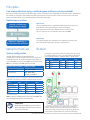
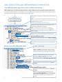
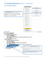
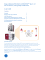
Two-step purification with ÄKTA™ pure, or
ÄKTA avant, using loop collection
Cue Card
Contents
Principles 2
Setup for multi-step purification 2
UNICORN methods 3
How to add user defined phases to a method 3
Description of the user defined phase in method one 4
Edit Sample Application phase in method two 5
Recommendations 6
Introduction
This cue card describes how to configure ÄKTA pure, set up methods, and perform a fully
automated two-step purification using two one-step UNICORN™ methods in a method queue.
ÄKTA avant can be configured applying the same principle. The fully automated two-step
purification is suitable for most columns and elution combinations.
Example methods for two-step purifications can be downloaded from
www.gelifesciences.com/AKTA, select ÄKTA pure or ÄKTA avant link under the heading Featured
Products. Then click on Related Documents tab and find the heading Cue Card.
The purpose of the cue card is to help users get started, and to inspire further multi-step method
development.
Principles
Two-step purification using a method queue with two one-step methods
By using one method for each purification step, column information from UNICORN can easily be used in the method.
This means, for example, that pressure and flow rate limits are correct for each column and the column log book
features can be utilized. Using a method queue allows full automation.
Method queue outline
Method one
The user defined phase in method one defines all functionality for
peak detection and loop collection of the eluted peak.
(see “Description of the user defined phase in method one”)
Method 1: Affinity and
peak elution to loop(s)
Up to 5 loops can be connected to the Loop valve V9-L.
Intermediate
storage in loop(s)
Method two
The collected peak from method one is loaded onto column two.
(see “Edit Sample Application phase in method two”)
Method 2: Desalting or
Gel filtration/Size exclusion
Setup for multi-step purification
System configuration
Several different ÄKTA pure and ÄKTA avant
configurations can be used. ÄKTA pure 25 is used in the
following example. To enable multistep functionality, a
Loop valve V9-L, a Column valve V9-C and a Mixer valve
V9-M or a Versatile valve V9-V will be needed.
Sample loading method
1
Modules needed
System pump
V9-L, V9-C, V9-M
Sample pump
V9-L, V9-V, V9-C,
Sample pump P9-S
1
Only applicable for ÄKTA pure as sample pump is always present in ÄKTA avant.
Flow path connections, when the Sample pump is used:
From
port
To
port
Pump P9-S
V9-V
3
V9-O or V9-Os Out
V9-V
4
1
1
V9-Inj
SaP
V9-V
V9-Inj
LoopF
V9-L
F
V9-L
E
V9-Inj
LoopE
Flow path connections, when the System pump is used
for sample loading. This is only applicable for ÄKTA pure
as the sample pump is always present in ÄKTA avant.
No. From
port
To
port
1 V9-O or V9-Os Out
V9-M
Re-inj
2 V9-M
Out
V9-Inj
SaP
3 V9-Inj
LoopF V9-L
F
4 V9-L
E
V9-Inj
LoopE
Up to 5 Loops
V9-L
V9-C
4
3
1
V9-V port 2 is not used.
Note: Connect a suitable loop to the Loop valve V9-L (see
Recommendations section, Loop selection) .
Important
2
V9-Inj
1
V9-M
V9-Os
Read ÄKTA pure Operating Instructions or
ÄKTA avant Operating Instructions before
using the instrument.
2
C9
U9-L
The illustration shows the two additional modules (blue)
and the needed connections (green) installed on ÄKTA pure
allowing two-step purification via re-injection (System pump
configuration). Standard flow path shown with dash lines.
Two-step purification with ÄKTA pure or ÄKTA avant using loop collection, 29090805 AB
UNICORN methods
Method one
Objective
Execute the first purification step on column one. Use
peak fractionation for the collection of the eluted peak in
a loop.
Description
During elution, when the watch condition for peak start
is fullfilled and the set delay volume has passed, valves
turn into position and the content in the peak is directed
to the loop for collection. The volume of the peak is
counted during the backwards filling of the loop from
port F to E on the loop valve.
Method two
Objective
Execute purification step two by forward loading (port E
to F on the loop valve) the collected peak content from
method one onto a second column, wash the column
and elute the sample.
Description
Loop collection and injection
The volume of collected peak is counted in step one,
using the start/stop volume count function. By inserting
the instruction hold counted volume, the injection
volume of step two can be equal to the collected peak
volume. The instruction is added at the end of the
sample load phase.
Due to the laminar flow, a larger volume than the one
collected should be used during sample loading on the
second column to empty the loop. Ideally, a volume
that is 1.3 times larger than the collected peak volume
should be used. Besides the laminar flow compensation,
a compensation volume equal to the volume of the flow
path from loop valve to column valve should also be
added. These two volumes constitute the chase* volume.
The instruction Empty loop with is used to set preferred
chase volume (laminar flow compensation volume + flow
path delay volume).
Note: The desalting and size exclusion columns have
limitations in the sample volumes that can be added.
* A chase volume is the volume of buffer that is used to push (i.e.
Add functionality to the method so that the sample
injection uses the correct loop and injects the volume of
the peak collected during step one.
How to add user defined phases to a method
Create and edit phases
The UNICORN Method Editor software is used when
creating and editing phases. Follow the steps below to
create a user defined phase:
• Rename a global phase
• Add new text instructions
• A user defined phase can be saved in the Phase
Library under Global Phases or Personal Phases for
future use.
For easy identification, modified phases can be renamed
starting with a # symbol.
The :T symbol is a software generated indication for a
text edited phase.
Note: For a comprehensive guide to creating methods
that can be run on ÄKTA pure or ÄKTA avant systems, refer
to the UNICORN Method Manual.
The illustration below shows an example of a UNICORN method
that can be used for purification step one
(Loop valve collect phase).
Method one: Loop valve collect phase
• The flow path for peak collection will be washed prior
to activating the watch functions for peak collection.
• During elution, the watch functions will be active and,
if fulfilled, will direct the peak to the loop. Details are
presented in the following pages.
• After peak collection the flow path used for peak
collection will be washed.
Two-step purification with ÄKTA pure or ÄKTA avant using loop collection, 29090805 AB
3
Description of the user defined phase in method one
User defined phase: Loop valve collect / Watch instructions
Note: The phase in this example has been designed for sample loading using the System pump and for collecting one
peak. Multiple peaks can be collected using the same principle if additional watch commands are added. When using
the Sample pump with ÄKTA pure the methods needs to be adjusted accordingly. The sample pump is always present in
ÄKTA avant which is reflected in the example method for ÄKTA avant
Volume from UV monitor to Outlet valve. In this example
0.20 ml.
Note: The volume of each component is found in ÄKTA pure User
Manual or ÄKTA avant User Manual. The volume of tubing can be
calculated using the formula:
Volume (ml) = Length (mm) × (i.d. (mm))2 × π /4.
Position on Outlet valve where the tubing from Mixer
valve V9-M port Re-Inj is connected.
Note: If a Sample pump is used to apply the sample, the
instruction where the flow is directed to V9-V (Outlet valve:
Outlet 3) needs to be followed by an instruction that sets V9-V to
position 1-4 & 2-3.
Position of the loop where the peak will be collected.
Variable for the flow rate used as set in Method Settings.
Volume from UV monitor to Loop valve. In this example
0.54 ml.
Block: Loop collect flowpath wash
Set Base to Volume, Any.
Note: If the Base is connected to column volume
and used flow rate for the wash is higher than the
column’s max flow rate, a warning will be issued.
Position on Outlet valve where the tubing from
Mixer valve V9-M port Re-inj is connected.
Flow rate used during Loop collect flow path wash.
Column position variable used as set in Method
Settings.
Variable for the flow rate used as set in Method
Settings.
Note: The use of the same variable allows the
changes in Method Settings to be reflected in the
Loop collect flow path wash block. For a detailed
description of variables, see UNICORN Method
Manual.
4
Two-step purification with ÄKTA pure or ÄKTA avant using loop collection, 29090805 AB
Edit Sample Application phase in method two
Phase: Sample Application
The Sample Application phase can be edited to utilize
the Hold counted volume UNICORN instruction.
Note: When performing text editing of the Sample
Application phase, the Phase Properties pane will be
replaced with a list of phase variables.
Block Inject
Additional instruction to Sample Application phase if
injection volume should equal collected loop volume.
It is possible to set the maximum volume to be used. In
this example 5.00 ml.
Chase volume (laminar flow compensation
volume + flow path delay volume). In this example
1.00 ml.
Two-step purification with ÄKTA pure or ÄKTA avant using loop collection, 29090805 AB
5
Recommendations
Peak detection
Loop selection
Set watch limits so that end peak is not triggered by start
peak values. For example, set start peak to greater than
100 mAU and end peak to less than 100 mAU.
Use at least 1.3 times the expected peak volume to
collect. Recommended to use Loop holder 29-0113-50.
Another way is to use the instruction Peak_start_max
before the peak end instruction (see UNICORN Method
Manual).
Column CIP and Equilibration
Take proper care in selecting the column for the second
step, especially with respect to maximum load volume.
To minimize the time the material in the eluted peak from
step one spends in the loop before being re-injected
during step two, you can create dedicated methods for
cleaning and equilibration procedures.
• CIP and re-equilibration of column one can be methods
executed after the method running step two of the
purification.
• Equilibration of column two can be a method executed
prior to starting method one.
Recommended combinations are:
Download
The peak volume should be larger than the delay volume
between the UV monitor and the Outlet valve. The delay
volume is typically 0.2 to 0.5 ml.
Column selection
Purification step one
Purification step two
1 ml HiTrap™
2 × 5 ml HiTrap Desalting
columns in series
1 ml HiTrap
Gel filtration/Size exclusion
column, i.d. 16 mm
5 ml HiTrap
HiPrep™ Desalting
Example methods for two-step purifications for ÄKTA
pure (either equipped with Sample pump or not) and
ÄKTA avant, can be downloaded from
www.gelifesciences.com/AKTA, select ÄKTA pure or ÄKTA
avant link under the heading Featured Products. Then
click on Related Documents tab and find the heading
Cue Card.
5 ml HiTrap
Gel filtration/Size exclusion
column, i.d. 26 mm
Ordering information
For local office contact information,
visit www.gelifesciences.com/contact
GE Healthcare Bio-Sciences AB
Björkgatan 30
SE-751 84 Uppsala
Sweden
www.gelifesciences.com/AKTA
GE and GE monogram are trademarks of General Electric
Company.
ÄKTA, HiPrep, HiTrap, and UNICORN are trademarks of General
Electric Company or one of its subsidiaries.
All other third party trademarks are the propery of their
respective owner.
Any use of UNICORN is subject to GE Healthcare Standard
Software End-User License Agreement for Life Sciences
Software Products. A copy of this Standard Software End-User
License Agreement is available on request.
For ordering information on columns, valves and tubing
visit www.gelifesciences.com/AKTApure, or
www.gelifesciences.com/AKTAavant.
© 2014-2015 General Electric Company – All rights reserved.
First published Mar. 2014
All goods and services are sold subject to the terms and
conditions of sale of the company within GE Healthcare which
supplies them. A copy of these terms and conditions is available
on request. Contact your local GE Healthcare representative for
the most current information.
GE Healthcare Europe GmbH
Munzinger Strasse 5, D-79111 Freiburg, Germany
GE Healthcare UK Limited
Amersham Place, Little Chalfont, Buckinghamshire, HP7 9NA,
UK
GE Healthcare Bio-Sciences Corp.
800 Centennial Avenue, P.O. Box 1327, Piscataway,
NJ 08855-1327, USA
GE Healthcare Japan Corporation
Sanken Bldg. 3-25-1, Hyakunincho Shinjuku-ku, Tokyo
169-0073, Japan
29090805 AB 06/2015