1
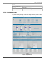
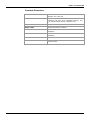
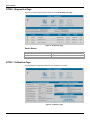
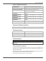
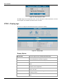
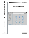
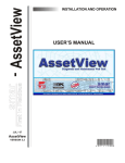
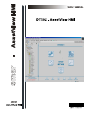
www.smar.com
Specifications and information are subject to change without notice.
Up-to-date address information is available on our website.
web: www.smar.com/contactus.asp
DT302 – AssetView HMI
DT302 - ASSETVIEW HMI
DT302 – Home page
This manual describes the pages developed for DT302 maintenance using AssetView.
The figure below shows the DT302 initial page and its options:
Figure 1 – Home page
The following sub-sections will describe each one of the pages developed for the device
maintenance.
DT302 - Identification Page
This page displays relevant information about the density transmitter. The user can easily identify
and specify the transmitter in the physical plant.
3
User’s Manual
Figure 2 – Identification page
Device
TAG
Indicates the tag associated to the transmitter in the
physical plant. The tag can have up to 8 characters.
DEVICE TYPE
Identifies the transmitter type for a specific manufacturer.
DEVICE SERIAL NUMBER
Indicates the transmitter serial number.
DEVICE REVISION
Indicates the transmitter revision.
HARDWARE REVISION
Indicates the transmitter hardware revision.
DEVICE ID
Indicates the transmitter identification code. This code can
have up to 32 characters.
MANUFACTURER
Identifies the transmitter manufacturer.
MAIN BOARD SERIAL NUMBER
Indicates the serial number of the transmitter main board.
FIRMWARE REVISION
Indicates the transmitter firmware revision.
DD REVISION
Indicates the DD revision.
ORDERING CODE
Indicates the transmitter ordering code.
Sensor
4
SENSOR TYPE
Indicates the transmitter sensor type.
SENSOR FLUID
Indicates the fluid of the transmitter’s sensor.
SENSOR RANGE CODE
Indicates the range code of the transmitter’s sensor.
SENSOR ISOLATION MATERIAL
Indicates the sensor isolation material.
SENSOR SERIAL NUMBER
Indicates the transmitter sensor serial number.
DT302 – AssetView HMI
Probe
DIAPHRAGM MATERIAL
PROCESS CONNECTION
MOUNTING
MODEL TYPE
FILL FLUID
Indicates the diaphragm material.
Indicates the process connection’s type, the transmitter can have
2, 3 or 4 wires.
Indicates the field mounting type.
Indicates the transmitter model type.
Indicates the cell’s fluid.
DT302 - Configuration Page
The density transmitter DT302 has a complete set of fieldbus commands to access any feature
implemented. The configuration page allows the user to configure the device’s parameters such as
input limits, ranges adjustments, configuration of the linearization table, among others
Figure 3 – Configuration page
5
User’s Manual
Device Operation Mode
Indicates the operation mode for the device:
OOS
If this mode is selected, the value of the Mode Block parameter will be Out of
Service for the Resource, Transducer and Analog Output blocks.
AUTO
If this mode is selected, the value of the Mode Block parameter will be Auto for the
Resource, Transducer, Display and Analog Output blocks.
MAN
If this mode is selected, the value of the Mode Block parameter will be Manual for
the Analog Output block, and Auto for the Resource, Transducer and Display
blocks.
Measurement Configuration
PV UNIT
Unit of the process variable.
PV LOWER RANGE
Lower limit of the process variable.
PV UPPER RANGE
Upper limit of the process variable.
MEASURED TYPE
Specifies the measured type for concentration and density.
MOUNTING POSITION
Indicates the probe mounting position (direct or reverse).
EU UNIT
Engineering unit.
EU 0%
Value of the pressure corresponding to 0%, in EU.
EU 100%
Value of the pressure corresponding to 100%, in EU.
TRANSDUCER TYPE
Indicates the transducer type according to its class.
Alert Configuration
MAXIMUM OFFSET DEVIATION
Indicates the maximum offset deviation before an alarm is
generated.
OVERPRESSURE LIMIT
Defines the maximum overpressure limit before an alarm is
generated.
MAXIMUM GAIN DEVIATION
Defines the maximum gain deviation before an alarm is
generated.
MAXIMUM NUMBER OF
OVERPRESSURE
Defines the maximum number of overpressure before an
alarm is generated.
Solid Polynomial
6
LIMIT LO
Lower limit in solid percent.
LIMIT HI
Upper limit in solid percent.
COEFF 0
Solid percent polynomial coefficient 0.
COEFF 1
Solid percent polynomial coefficient 1.
COEFF 2
Solid percent polynomial coefficient 2.
COEFF 3
Solid percent polynomial coefficient 3.
COEFF 4
Solid percent polynomial coefficient 4.
COEFF 5
Solid percent polynomial coefficient 5.
DT302 – AssetView HMI
Constants Parameters
GRAVITY
Gravity acceleration used
calculation. The unit is m/s².
HEIGHT
Distance between the two pressure sensors. The
engineering units have to be compatible with IN_1 and
IN_2. If are in mmH2O, the EU of height is in mm.
LIN DILATATION COEFF
Indicates the linear dilatation coefficient.
PRESS COEFF
Indicates the pressure coefficient.
TEMP ZERO
Offset coefficient
temperature.
TEMP GAIN
Gain coefficient
temperature.
ZERO ADJ TEMP
Temperature of zero adjustment.
HEIGHT MEAS TEMP
Temperature of measurement of distance between the
pressure sensors.
used
used
in
concentration/density
to
calibrate
the
transmitter
to
calibrate
the
transmitter
7
User’s Manual
DT302 - Diagnostics Page
The user can check the general status diagnostic in the DT302 Diagnostic Page.
Figure 4 – Diagnostics page
Device Status
MAXIMUM PRESSURE MEASURED
MAXIMUM TEMPERATURE MEASURED
CURRENT OFFSET
CURRENT SPAN
Indicates the maximum pressure measured.
Indicates the minimum temperature measured.
Indicates the calibration current offset.
Indicates the calibration current span.
DT302 - Calibration Page
This page displays configuration data used in the calibration procedures.
Figure 5 – Calibration page
8
DT302 – AssetView HMI
Pressure Calibration Information
CALIBRATION UNIT
Indicates the unit for the pressure calibration procedure.
SENSOR LOWER RANGE LIMIT
Indicates the lower limit for the range’s sensor.
SENSOR UPPER RANGE LIMIT
Indicates the upper limit for the range’s sensor.
MINIMUM SPAN
Indicates the minimum value allowed between the lower
and upper points of the calibration.
CURRENT LOWER POINT
CALIBRATION
Indicates the current lower point of the pressure
calibration.
CURRENT HIGHER POINT
CALIBRATION
Indicates the current higher point of the pressure
calibration.
FACTORY LOWER POINT
CALIBRATION
Indicates the factory’s lower point of the pressure
calibration.
FACTORY HIGHER POINT
CALIBRATION
Indicates the factory’s higher point of the pressure
calibration.
PRESSURE MEASURED
Indicates the pressure measured by the device.
TEMPERATURE MEASURED
Indicates the temperature measured by the device.
Temperature Calibration Information
CALIBRATION TEMPERATURE
Indicates the value of the last temperature calibration.
Calibration Information
WHO
Indicates the responsible for the last sensor calibration.
DATE
Indicates the date of the last sensor calibration.
LOCATION
Indicates the location of the last sensor calibration.
LAST CALIBRATION TYPE
Indicates the procedure of the last sensor calibration.
Calibration Methods
NOTE
When the transmitter is installed, it is recommended to run the Lower Concentration
Calibration procedure to minimize the mounting. Please refer to the transmitter manual for
further details.
LOWER CONCENTRATION CALIBRATION
This method is used when calibrating the lower density point. The user can select the calibration unit
and type the value of the density applied as reference value to the transmitter, observing the sensor
limits and the minimum span.
When this method is selected, a message appears warning the user that this procedure must be
executed when the process stops or the plant control is set to manual.
Click Yes, apply the density and wait for the sensor stabilization.
9
User’s Manual
Figure 6 – Stabilizing the sensor
Click OK, and the density measured will be shown.
Figure 7 – Confirming the Value of the Density
If the value is correct, click Yes to conclude this procedure. Otherwise, click No and type the density
value:
Figure 8 – New Density Value
Click OK to apply the new density value, and then click Yes to confirm the alteration, as shown in
the last figure. The calibration procedure will be concluded.
UPPER CONCENTRATION CALIBRATION
This method is similar to the Lower Concentration Calibration procedure described above. It is
used when calibrating the density with the user’s reference instead of the manufacturer’s reference.
Click Yes, apply the density and wait for the sensor stabilization.
Figure 9 – Stabilizing the sensor
Click OK, and the density measured will be shown.
10
DT302 – AssetView HMI
Figure 10 – Confirming the Value of the Density
If the value is correct, click Yes to conclude this procedure. Otherwise, click No and type the density
value:
Figure 11 – New Density Value
Click OK to apply the new density value, and then click Yes to confirm the alteration, as shown in
the last figure. The calibration procedure will be concluded.
TEMPERATURE CALIBRATION
This method is used for sensor temperature calibration. Click Ok, apply the temperature and wait for
the sensor stabilization.
Figure 12 - Stabilizing the Temperature
Click OK to start the calibration. The temperature measured will be shown.
Figure 13 - Confirming the Value of the Temperature
If the value is correct, click Yes to conclude this procedure. Otherwise, click No and type the
temperature value:
11
User’s Manual
Figure 14 - New Temperature Value
Click OK to apply the new temperature value, and then click Yes to confirm the alteration, as shown
in the last figure. The calibration procedure will be concluded.
DT302 – Display page
The user can configure the data that will be shown in the device's display.
Figure 15 – Display Page
Display Options
12
BLOCK TAG
Shows the tags list of the available instantiated blocks.
PARAMETER
Shows the list of available parameters to be displayed in the LCD
for the selected block in the Block Tag option.
SUB INDEX
Indicates the sub-index of the selected parameter.
MNEMONIC
Indicates the mnemonic of the selected parameter in the Parameter
option.
INC DEC
Indicates the value to be added or subtracted when acting the
parameter via local adjustment.
DECIMAL POINT NUMB
Indicates the number of digits after the decimal point that will be
shown in the LCD.
ACCESS
The user can select the access type of the selected parameter:
monitoring or action.
ALPHA NUM
Indicates if the alphanumeric field will be used for mnemonic or for
value.