1
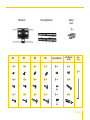
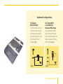
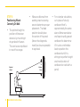
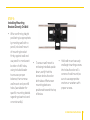
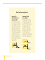
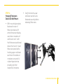
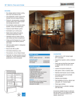
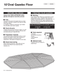
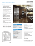
FSM-3760 / FULL SWING
WALL MOUNT
For 37”- 60” Flat Panel Screens
User Manual
Thank you for
choosing Gabor.
Thank you for choosing Gabor’s full swing flat panel screen wall
mount. This heavy-duty wall mount has been engineered to provide
your 37”-60” flatscreen monitor with sturdy, long-lasting support
that can be relied upon for years of viewing enjoyment.
With an impressive lineup of versatile mounting brackets
possessing various functionalities - along with a resilient, userfriendly mounting method that simplifies the installation process
- Gabor’s reputation for providing quality viewing solutions and longlasting dependability is readily apparent...from every angle.
2
Welcome
Welcome
3
Tools Required For Installation
Product Specifications
•
For Mounting 37”-60”
Flat Panel Screens
On Wooden Studs &
Concrete Walls
•
VESA Mounting
Pattern
Max. 800x500
•
Maximum Load
Capacity
132lbs/60kg
1. Power Drill
2. Phillips Screwdriver
Product Contents
Supplied Parts & Hardware
A (4) M4 Lock Washer
B (4) M4 X 12 Bolt
C (4) M4 X 30 Bolt
D (4) M5 Lock Washer
E (4) M5 X 12 Bolt
F (4) M5 X 30 Bolt
G (4) M6 Lock Washer
H (4) M6 X 12 Bolt
I (4) M6 X 35 Bolt
4
Specifications / Tools Required / Contents
3. Tape Measure
4. Socket Wrench
J (4) M8 Lock Washer
K (4) M8 X 16 Bolt
L (4) M8 X 40 Bolt
M(4) Spacer M4/M5
N (4) Spacer M6/M8
O (4) Washer M4/5
P (6) Washer
Q (6) Lag Bolt
R (6) Concrete Anchor
S (1) Hex Key (S3)
T (1) Bubble Level
Wall Mount
Mounting Brackets
Bubble
Level
T x1
M4
A x4
M5
D x4
M6
M8
G x4
J x4
Spacer/Washer
M x4
Bolt/Washer/
Anchor
Hex
Key
P x6
S x1
B x4
E x4
H x4
K x4
N x4
Q x6
C x4
F x4
I x4
L x4
O x4
R x6
Contents
5
Installation Instructions
STEP 1: Installing Dual
Mounting Brackets On
Rear Of Flatscreen
• Begin by aligning both
brackets on rear of
flatscreen device, while
ensuring that device
screen is resting on a
non-scratch surface.
The appropriate bolts
and washers should be
selected by measuring
the height, size and
position of holes on rear
of flatscreen device, and
determining which bolts
6
Installation Instructions
and washers fit best.
This may vary according to
specific brand, make and
model of flatscreen device.
• Use the shortest
configuration of bolts,
washers and spacers for
a secure fit. Spacers may
or may not be required
depending on curvature
of flat screen device and
rear dimensions.
• Ensure that brackets
are in proper position by
confirming that curved
metal arches are facing
downwards; align both
brackets by positioning
them at equal heights
and secure bolts tightly.
Note that bolts must
be hand-fastened into
holes with a screwdriver
or socket wrench, to
avoid overtightening and
possible damage.
Hardware Configurations
For Display
With Flat Back:
Install bracket directly to
flatscreen device using
only bolts and washers
provided; align bolt with
proper sized hole on
washer. (Fig. 1)
(Fig. 1)
For Display With
Curved Backs &
Recessed Mountings:
Install appropriate sized
spacer between bracket
and flatscreen device; then
fasten securely with bolts
and washers. (Fig. 2)
(Fig. 2)
Installation Instructions
7
STEP 2:
Positioning Mount
Correctly On Wall
• The optimal height to
position a flatscreen
device is by mounting it
at eye-level of viewer.
This can be accomplished
in one of two ways:
Eyelevel
Height
8
Installation Instructions
• Measure distance from
seating area to viewing
area to determine proper
placement. The ideal
position should place
the center of the panel
(where the diagonals
meet) as close as possible
to eye-level.
15°
Viewing
Angle
• For a simpler calculation,
cut a piece of sturdy
cardboard that’s
approximately the same
size as flatscreen device
and tape to wall; gaze at
cardboard to determine
if it is at a comfortable
level; reposition the
cardboard until it is
sitting at a perfect height
and mark location of
cardboard on wall with a
pencil.
STEP 3:
Installing Mounting
Bracket Directly On Wall
• After confirming height
positioning is appropriate
by marking wall with a
pencil, hold wall mount
of mounting bracket
firmly against wall and
use pencil to mark exact
location of drill holes,
using included leveler
to ensure a proper
balance; then remove
wall mount and pre-drill
holes (see sidebar for
specific mounting details
regarding sheetrock and
concrete walls).
• To ensure wall mount is
not being installed upside
down, verify that the
tension knobs found on
both sides of flatscreen
mounting plate are
positioned toward the top
of device.
• Hold wall mount securely
and begin inserting screws
into holes found on all 4
corners of wall mount; be
sure to use appropriate
anchors or washers with
proper screws.
Installation Instructions
9
Wall-Type Mounting Details
Mounting To
Wood Studs Under
Sheetrock Wall:
Pre-drill holes according
to markings on wall with a
5mm drill bit; be sure predrilled holes are at least
30mm deep and at least
12” apart; use appropriate
wall anchors to attach
wall mount (please verify
that included anchors are
appropriate).
Mounting To Solid
Concrete Wall:
Pre-drill holes according
to markings on wall with
a 12.7mm drill bit; be sure
pre-drilled holes are at
least 60mm deep; use
appropriate wall anchors
to attach wall mount
(please verify that included
anchors are appropriate).
12.7mm
12.7mm
10
Installation Instructions
STEP 4:
Hanging Flatscreen
Device On Wall Mount
• With mounting brackets
fastened to rear of
flatscreen device, lift
entire flatscreen display
over silver crossbars of
wall mount and - with
the flatscreen positioned
above the mount - lower
flatscreen panel while
hooking upper and lower
sections of brackets on
crossbars; ensure all 4
rubber-tipped arches
properly grip their
respective crossbars.
• Verify that both upper
and lower sections are
fastened securely before
releasing flatscreen.
Installation Instructions
11
STEP 5:
Positioning Installed
Wall Mount
• Upon installation
completion, secure power
cord for flatscreen device
by running it through
the plastic loops found
on bottom of extending
arms; then attach plug
to power source. Wall
mount can be positioned
in 3 easily extendable
configurations.
• To adjust tilt angle of
wall mount, turn tension
knobs found behind
both sides of flatscreen
12
Installation Instructions
mounting plate
counterclockwise; achieve
required tilt position
by gently pushing on
upper crossbar while
maintaining a firm grip
on lower one; tighten
securely by turning
tension knobs clockwise.
• It is recommended that
2 adults be used to
swivel wall mount sideto-side and/or adjust
panning angle. Begin
with Adult A grasping
right end of crossbars
and Adult B grasping
left end. Depending
on which direction is
required, 1 adult should
push crossbars while the
other pulls it into desired
position.
STEP 6:
Locking Installed Wall
Mount
• Flatscreen devices
attached to the wall
mount can be easily
secured with an ordinary
padlock (not included).
Begin by locating dual
round holes on the sides
of either mounting
bracket. Align silver
crescent-shaped
locking tab with round holes
and slide padlock through
holes; verify that crescentshaped tab curves inward
and ends directly under
mid-section of rubber-tipped
arches; close padlock to
firmly hold locking tab in
place.
Installation Instructions
13
Safety Warnings
1 Do not use this product for any
flat panel screen device other than
what it is intended for; the exact
specifications, size parameters and
weight limits are found both on the
product box and in the instruction
manual
2 It is strongly recommended that this
product be installed by a qualified
professional or installation contractor;
Gabor takes no responsibility for
any product damage or personal
injury resulting from mishandling,
incorrect mounting, faulty assembly
or improper use of this product
3 This product has been designed
specifically for mounting directly
on wooden studs or concrete
walls; depending on wall type and
material, the use of additional
appropriate mounting hardware and/
or accessories such as heavy-duty
anchors may be required
14
Safety Warnings
4 The supplied mounting hardware is
not intended for use on metal studs
or cinderblock walls, and may not be
appropriate for old or weak walls;
it is best to consult with a qualified
professional to determine whether
your walls are capable of supporting
this bracket
7 It is recommended that at least 2
people should perform the installation
process to prevent injury from
mishandling or dropping of the
product and/or flatscreen device;
proper safety gear and tools must be
utilized at all times when installing
product
5 Product must always be mounted
directly to center of wooden wall
studs or on a solid concrete wall
to properly support the weight of
the device; the wall may require
reinforcement prior to mounting
(i.e. metal studs; plaster on lath; or
irregular spacing of studs), which
should be determined by a qualified
professional
8 When installing this product, be sure
to refer to mounting instructions
detailed in this manual; failure to
abide by mounting instructions may
void product warranty
6 Do not mount device on structures
that may be affected by vibrations or
noticeable impacts; do not install near
heater, fireplace or any other source
of direct heat energy
10 Excessive exposure to liquids may
damage the finish of this product;
when cleaning this product, use only
a mild detergent solution and quickly
wipe dry with a soft cloth
9 This product may contain small parts
which can possibly pose a choking
hazard; keep out of reach of children
and pets
Customer
Support
ONE-YEAR LIMITED WARRANTY:
For more information or
to arrange service, visit
www.madebygabor.com
or call Customer Service
at 212-594-2353.
Product warranty is provided by
the Gradus Group.
www.gradusgroup.com
Gabor is a registered trademark
of the Gradus Group. © 2014 Gradus Group LLC. All Rights Reserved.
GG2
This GABOR product is warranted to the original purchaser to be free from defects in
materials and workmanship under normal consumer use for a period of one (1) year
from the original purchase date or thirty (30) days after replacement, whichever
occurs later. The warranty provider’s responsibility with respect to this limited
warranty shall be limited solely to repair or replacement, at the provider’s discretion,
of any product that fails during normal use of this product in its intended manner and
in its intended environment. Inoperability of the product or part(s) shall be determined
by the warranty provider. If the product has been discontinued, the warranty provider
reserves the right to replace it with a model of equivalent quality and function.
This warranty does not cover damage or defect caused by misuse, neglect,
accident, alteration, abuse, improper installation or maintenance. EXCEPT
AS PROVIDED HEREIN, THE WARRANTY PROVIDER MAKES NEITHER ANY
EXPRESS WARRANTIES NOR ANY IMPLIED WARRANTIES, INCLUDING BUT
NOT LIMITED TO ANY IMPLIED WARRANY OF MERCHANTABILITY OR FITNESS
FOR A PARTICULAR PURPOSE. This warranty provides you with specific legal
rights, and you may also have additional rights that vary from state to state.
To obtain warranty coverage, contact the Gabor Customer Service Department
to obtain a return merchandise authorization (“RMA”) number, and return the
defective product to Gabor along with the RMA number and proof of purchase.
Shipment of the defective product is at the purchaser’s own risk and expense.
Customer Support / Warranty
15
WWW.MADEBYGABOR.COM