1
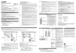
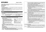
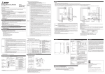
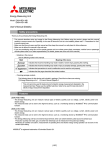
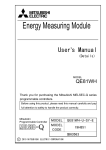
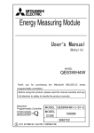
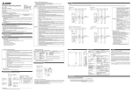
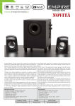
4. Name and function of each part
4.1 Name of each part
Energy Measuring Unit
Model
EMU4-BD1-MB
EMU4-HD1-MB
(1) EMU4-BD1-MB
If you are considering using this unit for special purpose such as nuclear power plants,
Voltage input terminals
aerospace, medical care or passenger vehiclesplease refer to our sales representative.
Voltage input terminals
Power supply terminals
LCD
display
・Before using this unit, please read both this manual and Details carefully and pay attention to safety to handle this unit correctly.
・Make sure that the end users read this manual and then keep the manual in a safe place for future reference.
ABOUT MANUALS
You can download User’s manual (Details) of this unit from the following site.
http://www.mitsubishielectric.co.jp/haisei/lvs/downloads/handling.htm
Terminal
symbol
P1、P2、P3
Frame GND terminal
Power supply terminals
User’s Manual (Digest)
Names of signals of terminal block (EMU4-BD1-MB)
(3) Back view
(2) EMU4-HD1-MB
Frame GND terminal
MA、MB
1k、1L、3k、3L
LCD
display
485+、485SLD
Ter
Operation
button
1. Features
Operation
button
Names of signals of terminal block (EMU4-HD1-MB)
(1) This Energy Measuring Unit can measure various types of electric quantity such as voltage, current, electric power and electric energy.
(2) The measurement data can also be transmitted to superior monitoring systems through MODBUS® RTU communication.
(3) In addition to the provision for measuring the quantity of electricity, the unit has two external input ports supporting both pulse input and contact input by way of switching (EMU4-HD1-MB).
With pulse input set, you can measure the production volume or the utility other than electricity, such as water, gas and air.
With contact input set, you can monitor status or alarm and measure the operating time of facility or the operating power.
MODBUS® is registered trademarks of Schneider Electric SA
Terminal
Description
symbol
P1/P1、P2/P0、 Connect the voltage input wire for the
measurement circuit.
P3/P3、NC/P2
Connect to ground (D type ground).
Connect the auxiliary power supply.
MA、MB
1k、1L、2k、2L、 Connect the secondary output of the dedicated
current sensor connected to the measurement
3k、3L
circuit’s current wire.
485+、485Connect the communication wire (MODBUS®
IEC rail
fixture
2. Checking package contents
This following items for this device and included in package. Check that no items are missing.
(2) User’s Manual (Digest) x1
(1) Energy Measuring Unit x1
3. Safety Precautions
Contact/ pulse output terminals
Current input terminals
Current input terminals
Communication terminals
(MODBUS® RTU)
3.2 Matters concerning the precaution before use
Communication terminals (MODBUS® RTU)
4.2 Functions of operation buttons
4.3 Functions of LCD
Meaning of symbol: ○ (Press), □ (Press more than 1 sec), ◎ (Press more than 2 sec), - (Press both at the same time)
DISP button
Name of Button
Operation
Mode
SET
Operation
Mode
SET button
◎
◎
Contact display
Integrated value
display
3.5 Maintenance Precautions
・Use a soft dry cloth to clean off dirt of the unit surface. Do not let a chemical cloth remain on the surface for an extended period of time nor wipe the surface with thinner or benzene.
・Check for the following items to use this unit properly for long time.
(1) Daily maintenance
(b) No abnormality with LCD
(c) No abnormal noise, smell or heat
(a) No damage on this unit
(2) Periodical maintenance (Once every 6 months to 1 year)
・No looseness with installation and wire connection
Do periodical maintenance under the electric outage condition. Failure to do so may cause electric shock, failure of the unit or a fire. Tighten the terminal regularly to prevent a fire. In
Caution
case a display unit is attached to a sensor unit, get off the display unit during maintaining or tightening terminals.
◎
◎
◎
◎
○
Menu display
○
(□)
○
(□)
○
(□)
○
(□)
○
Setting mode /
Confirmation
mode
□
○
Confirmation
mode / Setting
display
○
□
Confirmation
display of setting
reflection
○
○
○
◎
Event
Change measurement items
Change phase
Change harmonic order (at harmonic display)
Clear alarm (at alarm generation display with alarm keeping)
Transition to confirmation mode
2
Transition to setting mode
3
4
5
Clear contact latch
Transition to preset display
Transition to reset display of all data
Enter setting menu
Moving up or down of menu number
(Move at fast speed when pressing more than 1sec)
Change of setting items (forward)
Transition to setting menu number (at final setting item)
◎
◎
○
Setting mode /
Setting display
◎
When disposing of this unit, treat it as industrial waste.
For reduction of environment load, packaging materials are produced with cardboard, and this manual is printed on recycled paper.
Indicator
Description
1
Measured value
Display measured value digitally.
2
Measured item
Display measured item displayed on indicator No.1.
3
Communication
Light when connecting communication unit.
4
Energy
Light when measuring electric energy (consumption).
Measurement
Transition to setting menu
At "END" display, memorize changed setting and transition to operation
mode
At "CANCEL" display, throw away changed setting and transition to
operation mode
Moving up or down of setting value
Reset setting values to factory default (only effective at CANCEL display)
5
Setting
Indicator
lights on setting mode.
Indicator
lights on confirmation mode.
Setting mode or confirmation mode
Operation mode
Setting menu 1
Measurement display
End of setting menu
Basic setting
Setting menu 2
Communication setting
Setting menu 3
"CANCEL" display
Cancel change
of setting value
Setting menu 4
Input/output setting
*1
Phase wire
system
MODBUS®
address
Primary voltage
(with or without
VT)
MODBUS®
baud rate
Primary voltage
(with VT or direct
connection)
MODBUS®
parity
Sensor type
MODBUS®
stop bit
Setting menu 5
Alarm setting
*4
"End" display
Fix change of
setting value
Setting menu 6
Logging setting
*4
Test mode
*9
*8
Upper and lower
limit alarm
on or off
Logging module
ID setting
Reset method
of contact input
Upper and lower
limit alarm item
Clear logging
data
Contact/pulse
output
on or off
Upper and lower
limit alarm value
Contact/pulse
input
on or off
Test mode
*5
"-" + "DISP"
Transition automatically
Factroy default
Primary
current
Example of display on
setting mode
*6
Unit of pulse
output
Alarm delay time
Alarm reset
method
Display CO2 or
not
Example of display on
confirmation mode
*7
Current
demand time
limit
CO2 conversion
setting
Power demand
time limit
Display harmonic
current or not
Symbol
*2
For the case of special voltage (SP)
(Not available for 1P3W)
Primary voltage
(VT voltage)
*3
For the case of
special current (SP)
Primary special
voltage
Display operating
time or not
Primary special
voltage
Secondary
special voltage
<Note>
For details of setting menu 1, 2, 3, 4, 5 and 6, refer to User's manual (Details).
No display
*4
Count method of
operating time
*1: On confirmation mode, transition to operation mode.
*2: Transition only when selecting "SP" for "Primary current (VT)".
(For 3P4W, only special voltage is available when using VT.)
*3: Transition only when selecting "SP" for "Primary current (5A)".
*4: Setting available for EMU4-HD1-MB only.
*5: Transition only when selecting "CO.P." for "Contact/pulse input on or off".
*6: Transition only when selecting "PLS" for "Contact/pulse output on or off".
*7: Transition only when selecting "on" for "Display CO2 or not".
*8: Transition only when connecting logging module.
*9: Not displayed on setting mode.
Behavior
Transition from operation mode to setting mode.
Display harmonic
voltage or not
Sensor type
3.7 Disposal Precautions
3.8 About packaging materials and this manual
No.
Moving up or down of setting value
(Move at fast speed when pressing more than 1sec)
Change setting items (backward)
Transition to setting menu number (at beginning setting item)
Back to setting menu
Change setting items (forward)
Transition to setting menu number (at final setting item)
Change setting items (backward)
Transition to setting menu number (at beginning setting item)
3.6 Storage Precautions
To store this unit, turn off the power and remove wires, and put it in a plastic bag.
For long-time storage, avoid the following places. Failure to follow the instruction may cause a failure and reduced life of the unit.
・Places the Ambient temperature exceeds the range -10 - +60°C.
・Vibration and impact exceed the specifications.
・Places the Relative humidity exceeds the range 30-85% or places with dewfall.
・Places exposed to rain, water drop or direct sunlight.
・Dust, corrosive gas, saline and oil smoke exist.
・Places metal fragments or conductive substance are flying.
・Places the average daily temperature exceeds 35°C.
1
5. Procedures for setting
3.4 Precautions for Use
Caution
DISP
○
○
◎
-/RESET button
・Shut off the external power supply for the unit in all phases before installing or wiring. Failure to do so may cause an electric shock or damage of this unit.
・Use this unit within the ratings specified in this manual. If it is used outside the ratings, it may cause not only malfunction or failure but also fire burnout.
・Do not disassemble or modify this unit. It may cause failure, malfunction, injury or fire.
・Do not touch the live part such as connection terminal. It may cause electric shock, electric burn injury or burnout of the device. If any exposed conductor is found, stop the operation
immediately, and take an appropriate action such as isolation protection.
+/PHASE
○
Any person who is involved in the installation and the wiring of this unit should be fully competent to do this work.
Caution
-/RESET
+/PHASE button
3.3 Installation and Wiring Precautions
・Work under the electric outage condition when installing and wiring. Failure to do so may cause electric shock, a failure of the unit, a fire etc.
・When tapping or wiring, take care not to entering any foreign objects such as chips and wire pieces into this unit.
・Check the connection diagram when wiring. Wrong wiring may cause failure of the unit, a fire or electric shock.
・For protection against noise, transmission lines and input/output lines shall not be placed close to or bound together with the power lines and high-voltage lines.
・Strip the wires with proper length. Overlong stripping length may cause short to next wire. Shorter stripping length may cause contact failure.
・Take care not to short to next terminal by a filament. (Do not plate the wires with solder.)
・Do not connect more than two wires to one terminal of a terminal block for preventing loose contact and wires dropout.
・Use appropriate size of electric wires. If inappropriate size of electric wire is used, it may cause a fire due to generated heat.
・Tighten the screw within the specified torque. Under tightening can cause drop of the screw, short circuit or malfunction. Over tightening can damage the screw and/or unit, resulting in
drop, short circuit or malfunction.
・After tightening the screws, be sure to check all the screws tightened. Loose screw may cause malfunction of the unit, a fire or electric shock.
・Be sure to attach the terminal cover to prevent electric shock.
・Use the crimp-type terminal appropriated for the size of electric wires. If inappropriate crimp-type terminal is used, a wire breakage or a contact failure may occur, which may cause a
device malfunction, a failure, a burnout or a fire.
・FG terminal must be grounded according to the D-type ground (ground resistance is not exceed 100Ω).
High-voltage protective element is mounted between MA and FG, MB and FG. When applied high voltage, for example during a commercial frequency withstand voltage test, protective
element works to short between MA and FG, MB and FG.
・Do not directly touch any conductive part of the unit. Doing so can cause electric shock, failure or malfunction of the unit.
・When using this product, make sure to use it in combination with current sensor (EMU-CT50/CT100/CT250/CT400/CT600, EMU2-CT5 and EMU2-CT5-4W).Please not to exceed the
rating of this product for input of current sensor. For further details, please refer to current sensor manual to maintain the functionality and the accuracy of this product.
・The dedicated current sensor (EMU-CT50/CT100/CT250/CT400/CT600) is used only for low voltage circuit. It cannot be used for a high voltage circuit. EMU2-CT5 and CT5-4W should
be used with the secondary side (5A) of transformer transfixed. If it is connected with a high-voltage circuit by mistake, it may cause a burnout of the device and a fire. It is critically
dangerous. For the allowable maximum voltage of current sensor, refer to User’s manual (Details) 13 “Option devices” (1) Specifications.
・The dedicated current sensor has a polarity (directionality). Be careful about it when installing the unit.
・The wires to be connected to this unit shall be placed in a duct or fixed together by cramping. If the electric wires are not placed in the duct or cramped together, loosen wires or their
movement or careless stretch may cause a breakage of the unit or wire or a malfunction due to poor contact of electric wires.
・If the wires connected to this unit are strongly pulled off, it may cause a malfunction or a breakage to the unit or the wire.
・Do not exceed the specified voltage when doing an insulation resistance test and a commercial frequency withstand voltage test.
・To prevent persons with little knowledge about electric equipment from electric shock, panel must be taken either following measure.
Lock the panel so that only those who get an education about electric equipment and have sufficient knowledge can unlock, or shut off power supply automatically by opening the panel.
Cover the dangerous part of this unit.
X1、COMX
Y1、COMY
Control buttons have many functions as below.
・Use the unit in the specified usage environment and conditions.
・The setting of this unit (phase system, primary voltage and primary current, sensor type) is necessary before use it. Please refer to User’s Manual (Details) about each setting method.
Danger
RTU).
Connect to ground (D type ground).
Connect the “485-“ terminal (the unit at end of
the link).
Connect the contact/ pulse input wire.
Connect the contact/ pulse output wire.
SLD
Ter
Contact/ pulse input terminals
3.1 Precautions for Operating Environment and Conditions
This unit is premised on being used in pollution degree 2* environment. When used in higher pollution degree, protect this unit from pollution on another device side to be incorporated.
Over voltage category of measuring circuit in this unit is CAT II*, and that of auxiliary power circuit (MA, MB) is CAT II*.
Do not use this product in the places listed below. Failure to follow the instruction may cause malfunctions and a life decrease of product.
・Places the Ambient temperature exceeds the range -5 - +55°C.
・Places the average daily temperature exceeds 35°C.
・Altitude exceeds 1000m.
・Dust, corrosive gas, saline and oil smoke exist.
・Places in strong electromagnetic field or places large amounts of external noise exist.
・Vibration and impact exceed the specifications.
・Places exposed to direct sunlight
・Places metal fragments or conductive substance are flying.
・Places exposed to rain or water drop.
・Places the Relative humidity exceeds the range 30-85% or places with dewfall.
This unit is the open type device, which are designed to be housed within another device for prevention of electric shock. House this unit within the device such as the control panel before use.
For the precautions for the compliance of the system incorporating this unit with the EMC Directives, refer to the User’s Manual (Details).
*: For the definition of the pollution degree and the over voltage category, refer to EN61010-1/2010.
Description
Connect the voltage input wire for the
measurement circuit.
Connect to ground (D type ground).
Connect the auxiliary power supply.
Connect the secondary output of the dedicated
current sensor connected to the measurement
circuit’s current wire.
Connect the communication wire (MODBUS®
RTU).
Connect to ground (D type ground).
Connect the “485-“ terminal (the unit at end of
the link).
Operation of control button
Press both at the
same time for 2 sec
"SET" + "-"
Transition from operation mode to confirmation mode.
"SET"
Press for 2 sec
Select menu number or "End".
"+" or "-"
Press several times
Enter each setting display or transition to next item.
"SET"
Press once
Back to previous settting display.
"DISP"
Press once
Select setting value.
"+" or "-"
Press several times
Transition to "End" display.
Memorize changed setting and transition to operation
mode.
Select "CANCEL".
"SET"
Press once
"SET"
Press once
"+" or "-"
Cancel change of setting value.
"SET"
Press once
Skip other items during setting.
"SET"
Press for 1 sec
Reset setting values to factory default.
"SET"
Press once
Press once
6. Attachingand removing the unit
8. Dimensions
6.1 Mounting on IEC rail
●EMU4-BD1-MB
●EMU4-HD1-MB
Unit [mm]
CL
CL
MITSUBISHI
ELECTRIC
ENERGY MEASURING UNIT
43.5
P1,P2,P3,RATED 110/220V AC(~1P2W,1P3W,3P3W)
1k,1l,3k,3l RATED 66,66mA AC~ 50/60Hz
MEASUREMENT ITEM A,V,W,var,Hz,PF,Wh,varh
COMMUNICATION RS485(MODBUS RTU)
2400-38400bps
AUX.SUPPLY 100-240V~ 50/60Hz 10VA
53.5
EMU4-BD1-MB
90
MODEL
35.4
43.5
90
53.5
MITSUBISHI
ELECTRIC
ENERGY MEASURING UNIT
MODEL
P1,P2,P3,RATED 110,220,440V AC(~1P2W,1P3W,3P3W)
P1,P2,P3,P0 RATED 277/480V AC(~3P4W)
1k,1l,2k,2l,3k,3l RATED 66,66mA AC~ 50/60Hz
MEASUREMENT ITEM A,V,W,var,VA,Hz,PF,Wh,varh
CONTACT INPUT No Voltage contact
5V DC 7mA
CONTACT OUTPUT No Voltage a-contact
35V DC 75mA
COMMUNICATION RS485(MODBUS RTU)
2400-38400bps
AUX.SUPPLY 100-240V~ 50/60Hz 10VA
MITSUBISHI ELECTRIC CORPORATION
MADE IN JAPAN
6.2 Mounting on the panel
MITSUBISHI ELECTRIC CORPORATION
Mount the module to mounting plate by mounting screws
(M3×10), then mount the panel mounting attachment.
Screws for panel
Tightening torque : 0.63N・m
mounting
attachment
Outline of the unit
Outline of the unit
Mounting screws
φ4
2×
φ4
2×
φ4
2×
53.5
54.5
45.5
53.5
Recommended
screws
67
77
Item
*Please screw up the panel mounting attachment where there are
high levels of vibration.
*The screws (mounting screws and screws for panel mounting
attachment) are supplied with panel mounting attachment.
67
(75)
28
77
106
Measurement item
7. How to wire
7.1 Wiring
Follow the wiring diagram for external connections of this unit.
When using this unit, current sensor (EMU-CT50/CT100/CT250/CT400/CT600, EMU2-CT5 or EMU2-CT5-4W ) is necessary.
1P3W/3P3W (for low voltage circuit)
3P3W (for high voltage circuit)
1P2W (for low voltage circuit)
Power source side
Power source side
1
2
1
1
N
2
Voltage
circuit
1
3
2
single-phase 2-wire,
three-phase 3-wire
single-phase 3-wire
three-phase 4-wire
Rating
Power source side
3
3
Current circuit
P1 P2 P3
MA MB
P1 P2 P3
EMU-CT*** model
split current sensor
(50/100/250/400/600)
MA MB
P1/P1 P2/P0 P3/P3 NC/P2
Current
transformer ***/ 5A
1k 3k 485+ SLD
1L 3L 485- Ter
K
1L 2L 3L 485- Ter COMx COMY
RS485 (MODBUS®)
L
L
Load side
Power source side
3
N
Caution
P1/P1 P2/P0 P3/P3 NC/P2
Current
transformer ***/ 5A
1k 2k 3k 485+ SLD X1 Y1
1k
1l
3k
3l
2k
2l
5A current sensor
EMU2-CT5-4W
L
Contact
/pulse output
Contact
/pulse input
K
Load side
5A current sensor cable
EMU2-CB-Q5B-4W
5A current sensor cable
EMU2-CB-Q5B
RS485 (MODBUS®)
・For protection against noise, transmission lines and input/output lines shall not be placed close
to or bound together with the power lines and high-voltage lines. Keep distance as below
between them. (except for the terminal block)
Condition
distance
High-voltage line 600V or less
300mm or longer
Other high-voltage line
600mm or longer
・For the actual usage, connect the FG terminal to ground. (D-type ground: Type 3) Connect it
directly to the ground terminal.
・Do not connect to FG terminal during the insulation resistance test and pressure test.
Applicable wire
Tightening torque
Power supply terminals,
voltage input terminals
AWG24 - 16
(single wire / stranded wire)
0.8 N・m
Current input terminals,
input/ output terminals
AWG22 - 14
(single wire / stranded wire)
0.5 - 0.6N・m
RS485 (MODBUS®)
Recommended
crimp-type terminal
For M3 screw of
external diameter
below 5.6mm
For M3 screw of
external diameter
below 5.6mm
【EMU4-HD1-MB】
Applicable wire
Tightening torque
Power supply terminals,
voltage input terminals
AWG26 - 14
(single wire / stranded wire)
0.8 - 1.0 N・m
Current input terminals,
input/ output terminals
AWG22 - 14
(single wire / stranded wire)
0.5 - 0.6N・m
K
L
L
7.2 How to connect wires
・Use appropriate crimp-type terminal.
・Use electric wires as below, and tighten the terminal screws by the torque as below.
【EMU4-BD1-MB】
MA MB
1L 2L 3L 485- Ter COMx COMY
K
K
Load side
3P4W (for high voltage circuit)
2
3l
1k
K
l
Load side
3k
l
l
RS485 (MODBUS® )
Contact/
pulse output
Contact/
Pulse input
5A current sensor
EMU2-CT5
K
L
L
1k 2k 3k 485+ SLD X1 Y1
1l
1L 3L 485- Ter
K
L
MA MB
EMU-CT*** model
split current sensor
(50/100/250/400/600)
1k 3k 485+ SLD
4
67
75
15
60
Recommended
crimp-type terminal
For M3.5 screw of
external diameter
below 5.6mm
For M3 screw of
external diameter
below 5.6mm
・Make sure that before connecting the cable, the orientation of the current sensor is correct for attachment. K to L is the correct direction.
K: power source side, L: load side
・EMU-CT50/100/250/400/600 is used only for low voltage circuit. (Maximum voltage: 460V) It cannot be used for a high voltage circuit. EMU2-CT5 and EMU2-CT5-4W
should be used with the secondary side (5A) of transformer transfixed. If they are used for the circuit directly, they should be used under 200V. (Maximum voltage: 260V)
・Maximum voltage of the circuit connected to this unit directly is 260V for EMU4-BD1-MB, or 277 / 480V for EMU4-HD1-MB. For the circuit over this voltage, use the
transformer. Using the transformer, primary voltage is configurable up to 6600V.
・When screwing the terminals at both ends of the terminal block, be careful not to touch the projection of the terminal block cover.
・For MODBUS® communication wiring, recommended to have the extra length wires about 200mm (When extended to B / NET transmission from MODBUS® communication,
use of MODBUS® communication wiring is possible).
Specifications
EMU4-HD1-MB
single-phase 2-wire / single-phase 3-wire /
three-phase 3-wire / three-phase 4-wire
Electric energy (consumption, regeneration), Current, Current
Electric energy (consumption, regeneration), Current,
demand, Voltage, Electric power, Electric power demand, Reactive
Current demand, Voltage, Electric power, Electric power
power, Apparent power, Power factor, Frequency, Harmonic
demand, Reactive power, Power factor, Frequency,
current, Harmonic voltage, Reactive energy, Periodic electric
Reactive energy, Operating time
energy, Pulse count value, Operating time, Equivalent CO2
EMU4-BD1-MB
single-phase 2-wire / single-phase 3-wire /
three-phase 3-wire
Phase-wire system
Panel
22
26.5
26.5
22.5
cross recessed head screw with captive washer
and flat washer
M3×10
2pcs
60
9. Specifications
Model
Panel
15
Mounting screws
Panel mounting
attachment
45.5
67
75
4
LY303N900H11
REFER TO
MANUAL
27
The panel hole dimensions are as shown below.
And it can be attached to a panel of thickness
1.6 – 4.5mm.
27.5
Attached to the panel with screws (2 pcs).
Tightening torque : 0.63N・m
22.5
The panel hole dimensions are as shown below.
And it can be attached to a panel of thickness
1.6 – 4.5mm.
27
・Mounting
22.5
・Dimensions of hole panel
27.5
MADE IN JAPAN
・Mounting
1
LY303N900H01
REFER TO
MANUAL
・Dimensions of hole panel
CL
EMU4-HD1-MB
35.4
(2) Pull the unit
Frequency
Auxiliary power supply rating
Measurable circuit count
Input signal type
External input
Rated input
voltage/current
Output signal type
External output
Rated open/close
voltage/current
Operating temperature
Operating humidity
Storage temperature
Operating altitude
Standard
Product life expectancy
110V, 220V AC
110V, 220V, 440V AC
AC110V (b/w 1- and 2-side, 2- and 3-side),
AC220V(b/w 1- and 3-side)
AC110V (b/w 1- and 2-side, 2- and 3-side),
AC220V(b/w 1- and 3-side)
Non-compliant
Min: AC63.5V/110V, Max: AC277V/480V
50A, 100A, 250A, 400A, 600A AC
(The dedicated split type current sensor is used. Each value refers to the current at the primary side of the current sensor)
5A AC
(The dedicated split type current sensor is used. 5A current sensor is used together with the current transformer (CT), and the
primary-side current is configurable up to 6000A.)
50Hz-60Hz
100-240V AC (+10%, -15%), 50Hz-60Hz
1 circuit
No voltage a-contact 1 input
None
5V DC 7mA
None
No voltage a-contact 1 output
35V DC 75mA or 24V AC 75mA (Power factor = 1)
-5 - +55℃ (Under the conditions indicated in section 3.1)
30 - 85%RH (No condensation)
-10 - +60℃
1000m or below
EMC: EN61326-1: 2006
LVD: EN-61010-1: 2010
10 years (Under the conditions indicated in section 3.1)
10. Warranty
・The charge-free warranty is effective until the earlier of 1 year after the date of your purchase or 18 months after manufacturing. Repair shall be charged for the case failures
occur due to your intent or fault even during the charge-free warranty period.
・Our company shall not be liable to compensate for any loss arising from events not attributable to our company, opportunity loss and lost earning of the customer due to failure
of the product, and loss, secondary loss, accident compensation, damage to other products besides our products and other operations caused by a special reason regardless
of our company’s predictability.
Caution
If an abnormal sound, bad-smelling smoke, fever break out from this unit, switch it off promptly and don’t use it
11. Customer Service
Please contact us at the following locations.
1-8 Midori-cho, Fukuyama-shi, Hiroshima, 720-8647, Japan
Phone: +81-84-926-8142