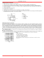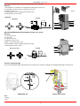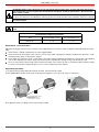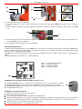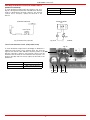
1
RX90
RX91
Gas burners
Low NOx series
MANUAL OF INSTALLATION - USE - MAINTENANCE
BURNERS - BRUCIATORI - BRULERS - BRENNER - QUEMADORES - ГОРЕЛКИ
M039175CD Rel. 3.0 07/2010
WARNINGS
THIS MANUAL IS SUPPLIED AS AN INTEGRAL AND ESSENTIAL PART OF THE PRODUCT AND MUST BE DELIVERED TO THE
USER.
INFORMATION INCLUDED IN THIS SECTION ARE DEDICATED BOTH TO THE USER AND TO PERSONNEL FOLLOWING PRODUCT INSTALLATION AND MAINTENANCE.
THE USER WILL FIND FURTHER INFORMATION ABOUT OPERATING AND USE RESTRICTIONS, IN THE SECOND SECTION
OF THIS MANUAL. WE HIGHLY RECOMMEND TO READ IT.
CAREFULLY KEEP THIS MANUAL FOR FUTURE REFERENCE.
1)
GENERAL INTRODUCTION
shall have qualified personnel carry out the following operations:
a
Remove the power supply by disconnecting the power cord from the
mains.
b) Disconnect the fuel supply by means of the hand-operated shut-off
valve and remove the control handwheels from their spindles.
z
The equipment must be installed in compliance with the regulations
in force, following the manufacturer’s instructions, by qualified personnel.
z Qualified personnel means those having technical knowledge in the
field of components for civil or industrial heating systems, sanitary
hot water generation and particularly service centres authorised by
the manufacturer.
z Improper installation may cause injury to people and animals, or
damage to property, for which the manufacturer cannot be held liable.
z Remove all packaging material and inspect the equipment for integrity.
In case of any doubt, do not use the unit - contact the supplier.
The packaging materials (wooden crate, nails, fastening devices, plastic
bags, foamed polystyrene, etc), should not be left within the reach of children, as they may prove harmful.
z Before any cleaning or servicing operation, disconnect the unit from
the mains by turning the master switch OFF, and/or through the cutout devices that are provided.
z Make sure that inlet or exhaust grilles are unobstructed.
z In case of breakdown and/or defective unit operation, disconnect the
unit. Make no attempt to repair the unit or take any direct action.
Contact qualified personnel only.
Units shall be repaired exclusively by a servicing centre, duly authorised
by the manufacturer, with original spare parts.
Failure to comply with the above instructions is likely to impair the unit’s
safety.
To ensure equipment efficiency and proper operation, it is essential that
maintenance operations are performed by qualified personnel at regular
intervals, following the manufacturer’s instructions.
z When a decision is made to discontinue the use of the equipment,
those parts likely to constitute sources of danger shall be made harmless.
z In case the equipment is to be sold or transferred to another user, or
in case the original user should move and leave the unit behind,
make sure that these instructions accompany the equipment at all
times so that they can be consulted by the new owner and/or the
installer.
z For all the units that have been modified or have options fitted then
original accessory equipment only shall be used.
z This unit shall be employed exclusively for the use for which it is
meant. Any other use shall be considered as improper and, therefore, dangerous.
The manufacturer shall not be held liable, by agreement or otherwise, for
damages resulting from improper installation, use and failure to comply
with the instructions supplied by the manufacturer.
Special warnings
z Make sure that the burner has, on installation, been firmly secured to
the appliance, so that the flame is generated inside the appliance
firebox.
z Before the burner is started and, thereafter, at least once a year,
have qualified personnel perform the following operations:
a
set the burner fuel flow rate depending on the heat input of the
appliance;
b
set the flow rate of the combustion-supporting air to obtain a combustion efficiency level at least equal to the lower level required by the
regulations in force;
c
check the unit operation for proper combustion, to avoid any harmful
or polluting unburnt gases in excess of the limits permitted by the
regulations in force;
d
make sure that control and safety devices are operating properly;
e
make sure that exhaust ducts intended to discharge the products of
combustion are operating properly;
f
on completion of setting and adjustment operations, make sure that
all mechanical locking devices of controls have been duly tightened;
g
make sure that a copy of the burner use and maintenance instructions is available in the boiler room.
z In case of a burner shut-down, reser the control box by means of the
RESET pushbutton. If a second shut-down takes place, call the
Technical Service, without trying to RESET further.
z The unit shall be operated and serviced by qualified personnel only,
in compliance with the regulations in force.
3)
z
z
z
z
z
2)
GENERAL INSTRUCTIONS DEPENDING ON FUEL USED
3a)
SPECIAL INSTRUCTIONS FOR BURNERS
z
z
The burner should be installed in a suitable room, with ventilation
openings complying with the requirements of the regulations in force,
and sufficient for good combustion.
z Only burners designed according to the regulations in force should
be used.
z This burner should be employed exclusively for the use for which it
was designed.
z Before connecting the burner, make sure that the unit rating is the
same as delivery mains (electricity, gas oil, or other fuel).
z Observe caution with hot burner components. These are, usually,
near to the flame and the fuel pre-heating system, they become hot
during the unit operation and will remain hot for some time after the
burner has stopped.
When the decision is made to discontinue the use of the burner, the user
ELECTRICAL CONNECTION
For safety reasons the unit must be efficiently earthed and installed
as required by current safety regulations.
It is vital that all saftey requirements are met. In case of any doubt,
ask for an accurate inspection of electrics by qualified personnel,
since the manufacturer cannot be held liable for damages that may
be caused by failure to correctly earth the equipment.
Qualified personnel must inspect the system to make sure that it is
adequate to take the maximum power used by the equipment shown
on the equipment rating plate. In particular, make sure that the
system cable cross section is adequate for the power absorbed by
the unit.
No adaptors, multiple outlet sockets and/or extension cables are permitted to connect the unit to the electric mains.
An omnipolar switch shall be provided for connection to mains, as
required by the current safety regulations.
The use of any power-operated component implies observance of a
few basic rules, for example:
- do not touch the unit with wet or damp parts of the body and/or with
bare feet;
- do not pull electric cables;
- do not leave the equipment exposed to weather (rain, sun, etc.)
unless expressly required to do so;
- do not allow children or inexperienced persons to use equipment;
z The unit input cable shall not be replaced by the user.
In case of damage to the cable, switch off the unit and contact qualified
personnel to replace.
When the unit is out of use for some time the electric switch supplying all
the power-driven components in the system (i.e. pumps, burner, etc.)
should be switched off.
3
DIRECTIVES AND STANDARDS
Gas burners
European directives:
- Directive 2009/142/EC - Gas Appliances;
- Directive 2006/95/EC on low voltage;
- Directive 2004/108/EC on electromagnetic compatibility
Harmonised standards :
-UNI EN 676 (Gas Burners;
-CEI EN 60335-1(Household and similar electrical appliances - Safety.
Part 1: General requirements;
- EN 50165 (Electrical equipment of non-electric appliances for household and similar purposes. Safety requirements.
3b) FIRING WITH GAS, LIGHT OIL OR OTHER FUELS
GENERAL
z The burner shall be installed by qualified personnel and in compliance with regulations and provisions in force; wrong installation
can cause injuries to people and animals, or damage to property, for
which the manufacturer cannot be held liable.
z Before installation, it is recommended that all the fuel supply system
pipes be carefully cleaned inside, to remove foreign matter that might
impair the burner operation.
z Before the burner is commissioned, qualified personnel should inspect the following:
a
the fuel supply system, for proper sealing;
b
the fuel flow rate, to make sure that it has been set based on the
firing rate required of the burner;
c
the burner firing system, to make sure that it is supplied for the designed fuel type;
d
the fuel supply pressure, to make sure that it is included in the range
shown on the rating plate;
e
the fuel supply system, to make sure that the system dimensions are
adequate to the burner firing rate, and that the system is equipped
with all the safety and control devices required by the regulations in
force.
z When the burner is to remain idle for some time, the fuel supply tap
or taps should be closed.
Light oil burners
European directives:
- Directive 2006/95/EC on low voltage;
- Directive 2004/108/EC on electromagnetic compatibility
Harmonised standards :
-CEI EN 60335-1(Household and similar electrical appliances - Safety.
Part 1: General requirements;
- EN 50165 (Electrical equipment of non-electric appliances for household and similar purposes. Safety requirements.
National standards :
-UNI 7824: Monobloc nebulizer burners for liquid fuels. Characteristics
and test methods
SPECIAL INSTRUCTIONS FOR USING GAS
Have qualified personnel inspect the installation to ensure that:
a
the gas delivery line and train are in compliance with the regulations
and provisions in force;
b
all gas connections are tight;
c
the boiler room ventilation openings are such that they ensure the air
supply flow required by the current regulations, and in any case are
sufficient for proper combustion.
z Do not use gas pipes to earth electrical equipment.
z Never leave the burner connected when not in use. Always shut the
gas valve off.
z In case of prolonged absence of the user, the main gas delivery
valve to the burner should be shut off.
Precautions if you can smell gas
a
do not operate electric switches, the telephone, or any other item
likely to generate sparks;
b
immediately open doors and windows to create an air flow to purge
the room;
c
close the gas valves;
d
contact qualified personnel.
z Do not obstruct the ventilation openings of the room where gas
appliances are installed, to avoid dangerous conditions such as the
development of toxic or explosive mixtures.
Heavy oil burners
European directives:
- Directive 2006/95/EC on low voltage;
- Directive 2004/108/EC on electromagnetic compatibility
Harmonised standards :
-CEI EN 60335-1 Household and similar electrical appliances - SafetyPart
1: General requirements;
- EN 50165 Electrical equipment of non-electric appliances for household
and similar purposes. Safety requirements.
National standards :
-UNI 7824: Monobloc nebulizer burners for liquid fuels. Characteristics
and test methods
Gas - Light oil burners
European directives:
- Directive 2009/142/EC - Gas Appliances;
- Directive 2006/95/EC on low voltage;
- Directive 2004/108/EC on electromagnetic compatibility
Harmonised standards :
-UNI EN 676 Gas Burners
-CEI EN 60335-1(Household and similar electrical appliances - Safety.
Part 1: General requirements;
- EN 50165 Electrical equipment of non-electric appliances for household
and similar purposes. Safety requirements.
National standards :
-UNI 7824: Monobloc nebulizer burners for liquid fuels. Characteristics
and test methods
Gas - Heavy oil burners
European directives:
- Directive 2009/142/EC - Gas Appliances;
- Directive 2006/95/EC on low voltage;
- Directive 2004/108/EC on electromagnetic compatibility
Harmonised standards :
-UNI EN 676 (Gas Burners;
-CEI EN 60335-1(Household and similar electrical appliances - Safety.
Part 1: General requirements;
- EN 50165 Electrical equipment of non-electric appliances for household
and similar purposes. Safety requirements.
National standards :
-UNI 7824: Monobloc nebulizer burners for liquid fuels. Characteristics
and test methods
4
C.I.B. UNIGAS - M039175CD
PART I: INSTALLATION MANUAL
GENERAL FEATURES
The gas coming from the supply line, passes through the valves group provided with filter and stabiliser. This one forces the pressure in
the utilisation limits. The electric actuator (14), that moves proportionally the air damper and the gas butterfly valve, uses an adjusting
cam (13) with variable shape. This one allows the optimisation of the gas flue values, as to get an efficient combustion. The combustion
head positioning determines the burner’s output. Fuel and comburent are routed into separated ways as far as the zone of flame generation (combustion chamber). The air (comburent) and fuel (gas) are forced into the combustion chamber. The control panel (1), placed
on the burner’s front side, shows each operating stage.
How to interpret the burner’s “Performance curve”
To check if the burner is suitable for the boiler to which it must be installled, the following parameters are needed:
z furnace input, in kW or kcal/h (kW = kcal/h / 860);
z backpressure (data are available on the boiler’s ID plate or in the user’s manual).
Example:
Furnace input: 600kW
Backpressure: 4mbar
In the “Performance curve” diagram (Fig. 4), draw a vertical line matching the furnace input value and an horizontal line matching the
backpressure value. The burner is suitable if the intersection point A is inside the performance curve.
Campo di lavoro bruciatori
Tipo P60 Mod. M-xx.x.IT.A.0.50 - M-.xx.x.IT.A.0.65
Contropressione in camera di
combustione mbar
8
7
6
5
A
4
3
2
1
0
-1
100
200
300
400
500
600
700
800
900
Potenza kW
Fig. 4
The values are referred to standard environmental conditions: 1013mbar, 15°C.
Checking the proper gas train size
To check the proper gas train size, it is necessary to know the available gas pressure value upstream the burner’s gas valve. Then
subtract the backpressure. The result is called pgas. Draw a vertical line matching the furnace input value (600kW, in the example),
quoted on the x-axis, as far as intercepitng the network pressure curve, according to the installed gas train (DN65, in the example).
From the interception point, draw an horizontal line as far as matching, on the y-axis, the value of pressure necessary to get the requested furnace input. This value must be lower or equal to the pgas value, calculated before.
Tipo / Type P60
M-...50 (Multibloc DUNGS MB-DLE 420 B01)
M-...65 (Filtro / Filter DN65+ SIEMENS VGD40.065 +SKP1x+SKP2x)
Minima pressione gas in
rete / Minimum inlet gas
pressure (mbar)
25
Rp 2" (50)
20
DN65
15
10
5
0
100
200
300
400
500
600
Potenza / Output (kW)
Fig. 5
5
700
800
900
C.I.B. UNIGAS - M039175CD
BURNERS FEATURES
Burner model identification
Burners are identified by burner type and model. Burner model identification is described as follows.
Type
RX90
Model
M-. PR. S. *.
(1)
(2) (3)
(1) BURNER TYPE
(2) FUEL
(3) OPERATION (Available versions)
(4) BLAST TUBE
(5) DESTINATION COUNTRY
(6) BURNER VERSION
(7) EQUIPMENT
A.
(4) (5)
1.
(6)
(8) GAS CONNECTION
see Specifications
80
(7)
(8)
RX90 - RX91
M - Natural gas
PR - Progressive
MD - Fully modulating
S - Standard
L - Extended
* - see data plate
A - Standard
1 = 2 valves + gas proving system
8 = 2 valves + gas proving system + maximum gas pressure switch
65 = DN65
50 = Rp2
80 = DN80
100 = DN100
Technical Specifications
BURNER TYPE
Output
min - max kW
RX90
RX91
288 - 1480
674 - 2008
Natural gas
Fuel
Category
Gas rate
(see next paragraph)
min.-max.
(Stm3/h)
Power supply
400V 3N~ 50Hz
Total power consumption
kW
3.5
Electric motor
kW
3
Approximate weight
kg
4.5
4
250
Protection
IP40
Operation
Progressive - Fully modulating
Gas train 50 Connection
ØValves / Connections
50 / Rp 2
Gas train 65
ØValves / Connections
65 / DN65
Gas train 80
ØValves / Connections
80 / DN80
Gas train 100
ØValves / Connections
100 / DN100
Operating temperature
°C
-10 ÷ +50
Storage Temperature
°C
-20 ÷ +60
Intermittent
≤ 80 mg/kWh
(Class 3 - EN676 - 2008)
NOx emissions
Note2:
71 - 213
(see Note 2)
Working service*
Note1:
30.5 - 157
Gas pressure
all gas flow rates are referred to Stm3/h (1013 mbar pressure, 15 °C temperature) and are valid for G20 gas (net calorific value: 34.02 MJ/Stm3).
Maximum gas pressure = 500mbar (with Siemens VGD gas valves).
Minimum gas pressure = see gas curves.
* NOTE ON THE BURNER WORKING SERVICE: for safety reasons, one controlled shutdown must be performed every 24 hours of
continuous operation.
6
C.I.B. UNIGAS - M039175CD
Country and usefulness gas categories
GAS
CATEGORY
COUNTRY
I2H
AT
ES GR SE
FI
IE
HU
IS
NO CZ
DK GB
IT
PT
CY
EE
LV
SI
MT
SK
BG
LT
I2E
LU
PL
-
-
-
-
-
-
-
-
-
I2E( R ) B
BE
-
-
-
-
-
-
-
-
-
I2L
NL
-
-
-
-
-
-
-
-
I2ELL
DE
-
-
-
-
-
-
-
I2Er
FR
-
-
-
-
-
-
-
-
-
-
-
-
-
-
-
-
-
-
-
-
-
-
-
-
-
-
-
-
-
-
-
-
-
-
-
-
-
-
-
-
-
-
-
-
-
-
-
-
-
-
-
-
-
-
-
-
-
-
-
-
-
-
-
-
-
-
-
-
-
-
-
-
-
-
-
-
-
-
-
-
-
-
-
-
-
-
7
RO TR CH
Overall dimensions (mm)
boiler recommended drilling template and burner flange
A
AA
AD AN
RX90
50
1168
242
35
RX90
65
1168
242
35
RX90
80
1168
242
RX90
100
1168
RX91
50
RX91
RX91
RX91
AP
Omin Oma
x
B
BB
C
CC
D
E
F
G
H
J
K
L
M
N
429 100
290
419
843
422
1294
860
434
228
258
329
360
464
M12
417
280
406 118
290
419
843
422
1391
957
434
228
258
288
360
464
M12
417
280
35
439 132
290
419
843
422
1393
959
434
228
258
307
360
464
M12
417
242
35
592 145
290
419
843
422
1483 1049
434
228
258
447
360
464
M12
1168
242
35
429 100
290
419
843
422
1294
860
434
273
303
329
360
464
65
1168
242
35
406 118
290
419
843
422
1391
957
434
273
303
288
360
80
1168
242
35
439 132
290
419
843
422
1393
959
434
273
303
307
360
100
1168
242
35
592 145
290
419
843
422
1483 1049
434
273
303
447
360
NOTE: the overall dimensions are referred to burners provided with Siemens VGD valves.
*DN = gas valves size
P
Q
R
S
U
V
W
Y
Z
310
295
522
148
374
624
216
649
228
185
310
295
551
148
403
750
292
649
228
185
280
310
295
592
148
444
750
322
649
228
185
417
280
310
295
672
148
524
824
382
649
228
185
M12
417
280
310
295
522
148
374
624
216
649
228
185
464
M12
417
280
310
295
551
148
403
750
292
649
228
185
464
M12
417
280
310
295
592
148
444
750
322
649
228
185
464
M12
417
280
310
295
672
148
524
824
382
649
228
185
C.I.B. UNIGAS - M039175CD
8
DN*
C.I.B. UNIGAS - M039175CD
Performance Curves
PRESSURE IN
COMBUSTION CHAMBER (mbar)
RX90
RX91
12
12
10
10
8
8
6
6
4
4
2
2
0
200
600
1000
1400
0
400
1800
800
1200
1600
2000
kW
kW
To get the input in kcal/h, multiply value in kW by 860.
Data are referred to standard conditions: atmospheric pressure at 1013mbar, ambient temperature at 15°C.
NOTE: The performance curve is a diagram that represents the burner performance in the type approval phase or in the laboratory
tests, but does not represent the regulation range of the machine. On this diagram the maximum output point is usually reached by adjsuting the combustion head to its “MAX” position (see paragraph “Adjusting the combustion head”); the minimum output point is reached setting the combustion head to its “MIN” position. During the first ignition, the combustion head is set in order to find a
compromise between the burner output and the generator specifications, that is why the minimum output may be different from the Performance curve minimum.
Pressure in the Network / gas flow rate curves
RX90
RX91
GAS PRESSURE (mbar)
50
100
R p 2" (50)
Rp 2" (50)
D N 65
40
DN65
80
D N 80
DN80
30
60
DN100
D N 100
20
40
10
20
0
0
20
40
60
80
100
120
140
160
180
Stm3/h
50
100
150
200
250
Stm3/h
Caution: the gas rate value is quoted on the x-axis, the related network pressure is quoted on the y-axis (pressure value in
the combustion chamber is not included). To know the minimum pressure at the gas train inlet, necessary to get the requested gas rate, add the pressure value in the combustion chamber to the value read on the y-axis.
9
C.I.B. UNIGAS - M039175CD
MOUNTING AND CONNECTING THE BURNER
Packing
The burners are despatched in wooden crates whose dimensions are:
1730mm x 1280mm x 1020mm (L x P x H)
H
Packing cases of this type are affected by humidity and are not suitable for stacking.
The following are placed in each packing case:
z burner with gas train;
z gasket to be inserted between the burner and the boiler;
z envelope containing this manual.
L
P
Fig. 6
To get rid of the burner’s packing, follow the procedures laid down by current laws on
disposal of materials.
Handling the burner
ATTENTION! The lhandling operations must be carried out by specialised and trained personnel. If these operations are not carried out correctly, the residual risk for the burner to overturn and fall down still persists.
To move the burner, use means suitable to support its weight (see paragraph “Technical specifications”).
The unpacked burner must be lifted and moved only by means of a fork lift truck.
The burner is mounted on a stirrup provided for handling the burner by means of a fork lift truck: the forks must be inserted into the A
anb B ways. Remove the stirrup only once the burner is installed to the boiler.
A
Stirrup
10
B
C.I.B. UNIGAS - M039175CD
Fitting the burner to the boiler
To install the burner into the boiler, proceed as follows:
1 make a hole on the closing door of the combustion chamber as described on paragraph “Overall dimensions”)
2 place the burner to the boiler: lift it up and handle it according to the procedure described on paragraph “Handling the burner”;
3 place the 4 stud bolts (5) on boiler’s door, according to the burner’s drilling template described on paragraph “Overall dimensions”;
4 fasten the 4 stud bolts;
5 place the gasket on the burner flange;
6 install the burner into the boiler;
7 fix the burner to the stud bolts, by means of the fixing nuts, according to the next picture.
8 After fitting the burner to the boiler, ensure that the gap between the blast tube and the refractory lining is sealed with appropriate
insulating material (ceramic fibre cord or refractory cement).
Keys
1 Burner
2 Fixing nut
3 Washer
4 Sealing gasket
5 Stud bolt
7 Blast tube
Matching the burner to the boiler
The burners described in this manual have been tested with combustion chambers that comply with EN676 regulation and whose
dimensions are described in the diagram . In case the burner must be coupled with boilers with a combustion chamber smaller in diameter or shorter than those described in the diagram, please contact the supplier, to verify that a correct matching is possible, with respect of the application involved. To correctly match the burner to the boiler verify the necessary input and the pressure in combustion
chamber are included in the burner performance curve; otherwise the choice of the burner must be revised consulting the burner manufacturer. To choose the blast tube lenght follow the instructions of the boiler manufacturer. In absence of these consider the following:
z Cast-iron boilers, three pass flue boilers (with the first pass in the rear part): the blast tube must protrude no more than 100 mm into
the combustion chamber.
z Pressurised boilers with flame reversal: in this case the blast tube must penetrate at least 50 - 100 mm into combustion chamber in
respect to the tube bundle plate.
The length of the blast tubes does not always allow this requirement to be met, and thus it may be necessary to use a suitably-sized
spacer to move the burner backwards or to design a blast tube tha suites the utilisation (please, contact the manifacturer).
Key
a) Heat output in kW
b) Length of the flame tube in meters
c) Flame tube firing intensity in MW/m3
d) Combustion chamber diameter (m)
Fig. 7 - Firing intensity, diameter and lenght of the test flame tube as a function of the heat
input in kW.
Fig. 7
11
C.I.B. UNIGAS - M039175CD
Gas train connections
The diagrams show the components of the gas trai included in the delivery and which must be fitted by the installer.The diagrams are in
compliance with the current laws.
ATTENTION: BEFORE EXECUTING THE CONNECTIONS TO THE GAS PIPE NETWORK, BE SURE THAT THE MANUAL
CUTOFF VALVES ARE CLOSED.
Gas train - 1
Gas train with valves group VGD 20/40.. with built-in gas pressure governor + VPS504 gas proving system
MANUFACTURER
4
4
INSTALLER
5
1
6
2
7
8
10
3
Gas train - 2 (Rp2)
Gas train with valves group MBC 1200SE (2 valves + gas filter + pressure governor) + VPS504 gas proving system
MANUFACTURER
4
4
18
INSTALLER
5
1
7
2
8
3
Gas train - 3(DN65/80/100)
Gas train with valves group MBC 1900/3100/5000SE (2 valves + gas filter + pressure governor) + VPS504 gas proving system
MANUFACTURER
4
4
19
INSTALLER
5
1
6
2
7
8
3
1
2
3
4
5
6
7
Burner
Butterfly valve
Gas proving system
Maximum gas pressure switch (option*)
Minimum gas pressure switch
Gas filter
Bellows unit
8
10
14
18
19
Manual cutoff valve
VGD Valves group
Pressure governor with filter
MBC Valves group (2” with filter provided)
MBC Valves group (DN65/80/100)
* Note: the high gas pressure switch can be mounted either upstream or downstream the gas valve but upstream the butterfly gas
valve (see item no.4 in the scheme above).
12
C.I.B. UNIGAS - M039175CD
Assembling the gas train
To assemble the main gas train, proceed as follows:
gas supply network
”direction” arrows for installation
1A
5
1B
Keys
3
1A..1E
2
3
4
5
1E
1C
1D
4
2
Gasket
Gas filter
Gas valves group
Bellows unit
Manual valve
Fig. 8 - Example for gas train
1-a) in case of threaded joints: use proper seals according to the gas used;
1-b) in case of flanged joints: place a gasket (no. 1A..1E - Fig. 8) between the items
2)
fasten all the items by the screws, according to the shemes shown, observing the mounting direction for each item (see figure
above).
NOTE: the bellows unit, the manual vale and the gaskets are not part of the standard supply.
ATTENTION: once the gas train is mounted according to the diagram on Fig. 8, the gas proving test mus be performed,
according to the procedure set by the laws in force.
ATTENTION: it is recommended to mount filter and gas valves to avoid that extraneous material drops inside the valves,
during maintenance and cleaning operation of the filters (both the filters outside the valves group and the ones built-in the
gas valves).
The procedures of installation fo the gas valves are showed in the next paragraphs, according to the gas train used:
threaded gas trains with Multibloc Dungs MBC..SE 1200 or Siemens VGD20..
z flanged gas trains with Multibloc Dungs MBC..SE 1900-3100-5000 or Siemens VGD40..
z
13
C.I.B. UNIGAS - M039175CD
Siemens VGD20.. and VGD40.. gas valves - with SKP2.. (pressure governor)
Mounting
z When mounting the VGD.. double gas valve, two flanges are required (as for VGD20.. model, the flanges are threaded);
z to prevent cuttings from falling inside the valve, first fit the flanges to the piping and then clean the associated parts;
z install the valve;
z the direction of gas flow must be in accordance with the direction of the arrow on the valve body;
z ensure that the bolts on the flanges are properly tightened;
z ensure that the connections with all components are tight;
z make certain that the O-rings and gaskets between the flanges and the double gas valve are fitted.
z Connect the reference gas pipe (TP in figure; 8mm-external size pipe supplied loose), to the gas pressure nipples placed on the
gas pipe, downstream the gas valves: gas pressure must be measured at a distance that must be at least 5 times the pipe size.
Leave the blowhole free (SA in figure). Should the spring fitted not permit satisfactory regulation, ask one of our service centres for a
suitable replacement.
Caution: the SKP2 diaphragm D must be vertical (see Fig. 11).
WARNING: removing the four screws BS causes the device to be unserviceable!
BS
BS
SIEMENS
POSITIONS
TP
SA
VGD..MOUNTING
D
BS
BS
SKP1.
SKP2.
7631z05/0101
Fig. 12
Fig. 10
Fig. 9
Fig. 11
TP
Fig. 13
14
C.I.B. UNIGAS - M039175CD
MULTIBLOC DUNGS MBC300-700-1200SE (Threaded valves group)
Mounting
1. Mount flange onto tube lines. Use appropriate sealing agent (see Fig. 14)
2. Insert MBC...SE. Note position of O rings (see Fig. 15).
3. Tighten screws A – H
4. After installation, perform leakage and functional test.
5. Disassembly in reverse order
MOUNTING
Fig. 14
OPTION
POSITIONS
'
PLQ['1
&
"
#
Ó
S%U
S%U
S%U
$
%
£
S%U
)
(
'1
S%U
Fig. 15
MULTIBLOCDUNGS MBC1900-3100-5000SE (Flanged valves group)
Mounting
1. Insert setscrews A
2. Insert seals
3. Insert setscrews B
4. Tighten setscrews A + B.
Ensure correct seating of the seal!
6. After installation, perform leakage and functional test.
7. Disassembly in reverse order.
#
#
#
#
Mounting positions
OPTION
"
"
"
njo/!6!y!EO
"
EO
21
2
Fig. 16
22
10 = pulse lines
Pressure adjusting range
The pressure adjusting range, downstream the gas valves group, changes according to the spring provided with the valve group.
1
1
2
2
DUNGS MBC..SE
Siemens SKP actuator
Keys
1 spring
2 cap
15
C.I.B. UNIGAS - M039175CD
DUNGS MBC valves:
Performance range (mbar)
4 - 20
20 - 40
40 - 80
80 - 150
-
red
black
green
Performance range (mbar)
0 - 22
15 - 120
100 - 250
Spring colour
neutral
yellow
red
Spring colour
Siemens VGD valves with SKP actuator :
Once the gas train in installed, execute the electrical connections for all its items (gas valves group, gas proving system, pressure
switches).
ATTENTION: once the gas train is mounted according to the diagram on Fig. 8, the gas proving test mus be performed,
according to the procedure set by the laws in force.
16
C.I.B. UNIGAS - M039175CD
ELECTRICAL CONNECTIONS
Respect the basic safety rules. make sure of the connection to the earthing system. do not reverse the phase and
neutral connections. fit a differential thermal magnet switch adequate for connection to the mains.
ATTENTION: before executing the electrical connections, pay attention to turn the plant’s switch to OFF and be
sure that the burner’s main switch is in 0 position (OFF) too. Read carefully the chapter “WARNINGS”, and the
“Electrical connections” section.
To execute the electrical connections, proceed as follows:
1 remove the cover from the electrical board, unscrewing the fixing screws;
2
execute the electrical connections to the supply terminal board as shown in the following diagrams,
3 check the direction of the fan motor (see next pargraph)
4 refit the panel cover.
WARNING: The burner is provided with an electrical bridge between terminals 6 and 7; when connecting the high/
low flame thermostat, remove this bridge before connecting the thermostat.
IMPORTANT: Connecting electrical supply wires to the burner teminal block MA, be sure that the ground wire is
longer than phase and neutral ones.
Connect the three-phase supply to terminals L1, L2, L3 and PE (ground); then shunt the phase and neutral wires (Fig. 18) for the auxiliaries on the printed circuit (N-terminal = neutral; L-terminal = phase).
Auxiliary relais power supply
Alimentazione ausiliari
Fig. 17: Power supply terminal board
Fig. 18: Electric motor connection
Keys - Fig. 18
IG: main switch
KM1: fan motor contactor
M: fan motor
TV: fan motor thermal cutout
17
C.I.B. UNIGAS - M039175CD
Electrical wiring diagram for burners provided with printed circuit (standard configuration).
.As far as connections, refer to the terminal block shown on Fig. 19.
Fig. 19: Terminal board for connections on printed circuit
1 Connect the signal conductors from the boiler to the burner, as for the next elements (Fig. 20 - Fig. 22):
ST: thermostat/pressure switch series
TAB: High/low flame thermostat
2 Connect the signal conductors from the burner to the boiler, as for the next elements (Fig. 20 - Fig. 22)
LB: Burner’s lockout signalling LED
LSPG: Gas proving system lockout signalling LED
3 In case of modulating burners, the 5, 6 and 7 terminals, on the MA teminal block, are already connected to the output controller
(mod. RWF40). A 4-pole plug coming out from the electrical panel is provided for the temperature and pressure probes connections (see Fig. 21).
Note: the output controller modulator is provided according to the ordered probe
Fig. 20: Progressive burners
RWF40 >>>
Fig. 22: Fully modulating burners
Fig. 21: Probes connection
Probes connection by means of the 7-pins plug (Fig. 23) - see Fig. 21 for connections.
Fig. 23
18
C.I.B. UNIGAS - M039175CD
Electrical wiring diagram for burners with no printed circuit provided
If the burner is ordered without printed circuit, follow the next connections diagrams.
Fig. 24 - Progressive burners
Fig. 26 - Fully modulating burners
Fig. 25 - Probes connection
(**) Probes connection
Probes connection by means of the 7-pins plug (Fig. 27) - see Fig. 25 for connections.
Fig. 27
Rotation of fan motor
Once the electrical connection of the burner is executed, remember to check the rotation of the fan motor. The motor should rotate
according to the “arrow” symbol on the body. In the event of wrong rotation, reverse the three-phase supply and check again the rotation of the motor.
CAUTION: check the motor thermal cut-out adjustment
NOTE: the burners are supplied for three-phase 400V supply, and in the case of three-phase 230V supply it is necessary to
modify the electrical connections into the terminal box of the electric motor and replace the overload tripped relay.
19
C.I.B. UNIGAS - M039175CD
ADJUSTING AIR AND GAS
Combustion head gas pressure curves depending on the flow rate
Curves are referred to pressure = 0mbar in the combustion head!
The curves referred to the gas pressure in the combustion head, depending on the gas flow rate, are referred to the burner properly
adjusted (percentage of residual O2 in the flues as shown in the “Recommended combustion values” table and CO in the standard
limits). During this stage, the combustion head, the gas butterfly valve and the actuator are at the maximum opening. Refer to Fig. 28,
showing the correct way to measure the gas pressure, considering the values of pressure in combustion chamber, surveyed by means
of the pressure gauge or taken from the boiler’s Technical specifications.
1
2
4
3
Fig. 28
Key
1 Generator
2 Pressure outlet on the combustion chamber
3 Gas pressure outlet on the butterfly valve
4 Differential pressure gauge
Measuring the gas pressure in the combustion head
In order to measure the pressure in the combustion head, insert the pressure gauge probes: one into the combustion chamber’s pressure outlet (Fig. 28-2) to get the pressure in the combustion chamber and the other one into the butterfly valve’s pressure outlet of the
burner (Fig. 28-3). On the basis of the measured differential pressure, it is possible to get the maximum flow rate: in the pressure - rate
curves (showed on the next paragraph), it is easy to find out the burner’s output in Stm3/h (quoted on the x axis) from the pressure
measured in the combustion head (quoted on the y axis). The data obtained must be considered when adjusting the gas flow rate.
NOTE: THE PRESSURE-RATE CURVES ARE GIVEN AS INFORMATION ONLY; FOR A PROPER SETTING OF THE GAS RATE,
PLEASE REFER TO THE GAS METER READING.
20
C.I.B. UNIGAS - M039175CD
Pressure in combustion head - gas flow rate curves
RX90
RX91
30
Gas pressure in
combustion head (mbar)
55
25
45
20
35
15
25
10
5
15
0
5
20
40
60
80
100
120
140
160
Stm3/h
60
80
100
120
140
160
180
200
220
Stm3/h
Caution: the gas rate value is quoted on the x-axis, the related network pressure is quoted on the y-axis (pressure value in
the combustion chamber is not included). To know the minimum pressure at the gas train inlet, necessary to get the requested gas rate, add the pressure value in the combustion chamber to the value read on the y-axis.
21
C.I.B. UNIGAS - M039175CD
Adjusting air and gas flow rates
Gas Filter
The gas filters remove the dust particles that are present in the gas, and prevent the elements at risk (e.g.: burners, counters and regulators) from becoming rapidly blocked. The filter is normally installed upstream from all the control and on-off devices.
VPS504 Gas proving system
LC
LB
The VPS504 check the operation of the seal of the gas shut
off valves. This check is carried out as soon as the boiler
thermostat TAB gives a start signal to the burner, creating,
by means of the diaphragm pump inside it, a pressure in the
test space of 20 mbar higher than the supply pressure.
When wishing to monitor the test, install a pressure gauge
into the pressure supply point PA.
If the test cycle is satisfactory, after a few seconds the consent light LC (yellow) comes on. Otherwise, the lockout light
LB (red) comes on.
To restart, it is necessary to reset the appliance by pressing
the pushbutton LB.
PA
Actuator
The actuator provided can be either Berger STM30../Siemens SQM40.. (see page 25) or Siemens SQL33.. (see page 27).
22
C.I.B. UNIGAS - M039175CD
Adjusting air and gas flow rates
ATTENTION: before starting the burner up, be sure that the manual cutoff valves are open and check that the pressure upstream the gas train complies the value quoted on paragraph “Technical specifications”. Be sure that the
mains switch is closed.
.ATTENTION: During commissioning operations, do not let the burner operate with insufficient air flow (danger of formation
of carbon monoxide); if this should happen, make the gas decrease slowly until the normal combustion values are achieved.
WARNING: NEVER LOOSE THE SEALED SCREWS! OTHERWISE, THE DEVICE WARRANTY WILL BE IMMEDIATELY INVALIDATE!
IMPORTANT! the combustion air excess must be adjusted according to the suggested values in the following
chart:
Recommended combustion parameters
Fuel
Recommended (%) CO2
Recommended (%) O2
Natural gas
9 ÷ 10
3 ÷ 4.8
Adjustments - brief description
Adjust the air and gas flow rates at the maximum output (“high flame”) first, by means of the air damper and the adjusting cam respectively.
z Check that the combustion parameters are in the suggested limits.
z
z
z
Check the flow rate measuring it on the counter or, if it was not possible, verifying the combustion head pressure by means of a differential pressure gauge, as described on page 21.
Then, adjust the combustion values corresponding to the points between maximum and minimum: set the shape of the adjusting
cam foil. The adjusting cam sets the air/gas ratio in those points, regulating the opening-closing of the throttle gas valve.
Set, now, the low flame output, acting on the low flame microswitch of the actuator in order to avoid the low flame output increasing
too much or that the flues temperature gets too low to cause condensation in the chimney.
Adjustment procedure
To change the burner setting during the testing in the plant, follow the next procedure.
On the DUNGS MBC..SE gas valves group, set the pressure regulator to 1/3 of its stroke, using a 2.5 allen key.
1#S
*OOFOTFDITLBOUTDIMàTTFM/P
"MMFOLFZOP
$MÏEFTJYQBOTNÉMFOP
$IJBWFFTBHPOBMFDBWBOS
Pressure setting
Now, adjust the burner according to the actuator model provided.
23
C.I.B. UNIGAS - M039175CD
Air and Gas Flow Rate Settings by means of Berger STM30../Siemens SQM40.. actuator
mensions
Dimensions in
VI
SQM4...
V
IV
III
Actuator cams
II
I
II
III
I
High flame
Stand-by and Ignition
Low flame
MAN-AUTO
MAN-AUTO
Berger STM30
Siemens SQM40
1
2
3
4
Check the fan motor rotation and act directly on the related contactor (see next picture).
Before starting the burner up, drive the high flame actuator microswitch matching the low flame one (in order to let the burner operates at the lowest output) to safely achieve the high flame stage.
Turn the burner on by means of its main switch A (see next picture): if the burner locks (LED B on in the control panel) press the
RESET button (C) on the control panel - see chapter “OPERATION”.
Start the burner up by means of the thermostat series and wait until the pre-purge time comes to an end and the burner starts up;
B
C
A
5
6
7
8
drive the burner to high flame stage, by means fo the thermostat TAB (high/low flame thermostat - see Wiring diagrams), as far as
fully-modulating burners, see related paragraph.
Then move progressively the microswitch to higher values until it reaches the high flame position; always check the combustion
values and eventually adjusting the gas by means of the valves group stabiliser.
go on adjusting air and gas flow rates: check, continuosly, the flue gas analisys, as to avoid combustion with little air; dose the air
according to the gas flow rate change following the steps quoted below;
acting on the pressure stabiliser of the valves group, adjust the gas flow rate in the high flame stage as to meet the values
requested by the boiler/utilisation:
- Siemens VGD valves group: remove cap T and act on the VR adjusting screw to increase or decrease the pressure and consequently the gas rate; screwind VR the rate increases, unscrewing it decreases (see next figure).
- Dungs MBC..SE valves group: act on its pressure governor to increase or decrease the pressure and consequently the gas
rate.
24
C.I.B. UNIGAS - M039175CD
T
VR
1#S
*OOFOTFDITLBOUTDIMàTTFM/P
"MMFOLFZOP
$MÏEFTJYQBOTNÉMFOP
$IJBWFFTBHPOBMFDBWBOS
Siemens VGD..
:
9
Dungs MBC..SE
To adjust the air flow rate in the high flame stage, loose the RA nut and screw VRA as to get the desired air flow rate: moving
the rod TR towards the air damper shaft, the air damper opens and consequently the air flow rate increases, moving it far from the
shaft the air damper closes and the air flow rate decreases.
Note: once the procedure is perfomed, be sure that the blocking nut RA is fasten. Do not change the position of the air damper
rods.
TR
RA
VRA
10 Only if necessary, change the combusiton head position: the burner is factory-set according to its combustion head model.
z
LX90-91-510: The burner is factory-set with the head in its "all-ahead" position, as for the minimum output. To operate at a higher
power, loosen the VB screw and slightly move the combustion head backwards, turning clockwise the knob VRT. Fasten VB screw
when the adjustment is accomplished.
“all-ahead” position
VB
VRT
“all-backwards” head position
Attention! if it is necessary to change the head position, repeat the air and gas adjustments described above.
11 the air and gas rate are now adjusted at the maximum power stage, go on with the point to point adjustement on the SV adjusting
cam as to reach the minimum output point.
12 as for the point-to-point regulation, move the gas low flame microswitch (cam III) a little lower than the maximum position (90°);
13 set the TAB thermostat to the minimum in order that the actuator moves progressively towards the low flame position;
14 move cam III to the minimum to move the actuator towards the low flame until the two bearings find the adjusting screw that refers
to the lower position: screw V1 to increase the rate, unscrew to decrease.
15 Move again cam III towards the minimum to meet the next screw on the adjusting cam and repeat the previous step; go on this way
as to reach the desired low flame point.
16 Now adjust the pressure switches (see next par.).
25
C.I.B. UNIGAS - M039175CD
V
V
SV
SV
SC
Gas throttle valve open
ID
Gas throttle valve closed
17 If it is necessary to change the burner output in the low flame stage, move cam III: the low flame position must never match the
ignition position, that is why cam III must be set 20°- 30° more than cam II.
18 Turn the burner off; then start the burner up again. If the adjustment is not correct, repeat the previous steps.
Adjustment by the Siemens SQL33.. actuator
1
2
open the electrical panel to check the fam motor rotation and act directly on the related contactor (see next picture).
Turn the burner on by means of its main switch A: if the burner locks (LED B on in the control panel) press the RESET button (C)
on the control panel - see chapter “OPERATION” on page 31 .
B
C
A
3
4
5
6
Start the burner up by means of the thermostat series and wait until the pre-purge time comes to an end and that the burner starts
up;
the burner starts up with the actuator on the ignition position, set it to the MAN (manual mode), by the MAN/AUTO selector (ignition
position= read on the air damper index ID1 - see picture on pag.31);
disconnect the TAB thermostat removing the wire from the terminal no. 6 or by setting MAN on the RWF40 modulatore or by setting 0 by means of the CMF switch (only for fully-modulating burners);
manually drive the adjusting cam SV to the high flame position and set the actuator to the AUTO mode (by the related switch - see
picture) to lock the adjusting cam.
SQL330.. actuator cams
A = (red) cam locking lever for “high flame”
S = (green) cam locking lever for “stand-by and ignition”
BF = Low flame
F = plastic cam
AUT
MAN
BF
7
8
F
S
A
go on adjusting air and gas flow rates: check, continuosly, the flue gas analisys, as to avoid combustion with little air; dose the air
according to the gas flow rate change following the steps below;
acting on the pressure stabiliser of the valves group, adjust the gas flow rate in the high flame stage as to meet the values
requested by the boiler/utilisation:
26
C.I.B. UNIGAS - M039175CD
- Siemens VGD valves group: remove cap T and act on the VR adjusting screw to increase or decrease the pressure and consequently the gas rate; screwind VR the rate increases, unscrewing it decreases (see next figure).
- Dungs MBC..SE valves group: act on its pressure governor to increase or decrease the pressure and consequently the gas
rate.
T
VR
1#S
*OOFOTFDITLBOUTDIMàTTFM/P
"MMFOLFZOP
$MÏEFTJYQBOTNÉMFOP
$IJBWFFTBHPOBMFDBWBOS
Siemens VGD..
9
Dungs MBC..SE
To adjust the air flow rate in the high flame stage, loose the RA nut and screw VRA as to get the desired air flow rate: moving
the rod TR towards the air damper shaft, the air damper opens and consequently the air flow rate increases, moving it far from the
shaft the air damper closes and the air flow rate decreases.
Note: once the procedure is perfomed, be sure that the blocking nut RA is fasten. Do not change the position of the air damper rods.
TR
RA
VRA
10 Only if necessary, change the combusiton head position: the burner is factory-set according to its combustion head model.
The burner is factory-set with the head in its "all-ahead" position, as for the minimum output. To operate at a higher power, loosen the
VB screw and slightly move the combustion head backwards, turning clockwise the knob VRT. Fasten VB screw when the adjustment
is accomplished.
“all-ahead” position
VB
VRT
“all-backwards” head position
Attention! if it is necessary to change the head position, repeat the air and gas adjustments described above.
11 the air and gas rate are now adjusted at the maximum output, go on with the point to point adjustment on the SV1 adjusting cam as
to reach the minimum output point: gradually move the adjusting cam in order to adjust each of the V1 screws as to set the cam foil
shape as described on the next steps:
12 to change the SV position set the actuator on the manual mode (MAN), turn the adjusting cam SV and set again the actuator to the
AUTO mode to lock the adjusting cam;
13 act on the V screw that mathces the bearings referring to the adjusting cam position;
14 to adjust the next screw, set again the actuator mode to MAN, turn the adjusting cam and set the actuator to AUTO mode to lock
the adjusting cam on the next screw; adjust it and go on this way to adjust all the screws in order to set the cam foil shape, according to the combustion values read.
15 Once the cam foil shape is defined, reconnect the TAB thermostat reconnecting the wire to the terminal no.6 or setting the RWF40
burner modulator to AUTO or the CMF switch to 3 (only for fully-modulating burner).
27
C.I.B. UNIGAS - M039175CD
V
V
SV
SV
SC
Gas throttle valve open
ID
Gas throttle valve closed
16 Turn the burner off, then start it up again.
17 Once the pre-purge time comes to end, drive the burner to the high flame stage by the TAB thermosta and check the combustion
values;
18 drive the burner to low flame, if necessary adjust the low flame size (ouput) by inserting a screwdriver on the slot F to move the BF
cam.
BF
F
19 The low flame position must never match the ignition position that is why cam BF1 must be set 20°- 30° more than the ignition position (see ID index on previous pictures).
20 Now adjust the pressure switches (see next parahraphs).
Fully modulating burners
To adjust the fully-modulating burners, use the CMF switch on the burner control panel (see next picture), instead of the TAB thermostat as described on the previous paragraphs about the progressive burners. Go on adjusting the burner as described before, paying
attention to use the CMF switch intead of TAB.
The CMF position sets the oprating stages: to drive the burner to the high-flame stage, set CMF=1; to drive it to the low-flame stage, set
CMF=2.
To move the adjusting cam set CMF=1 or 2 and then CMF=0.
CMF = 0
CMF = 1
CMF = 2
CMF = 3
stop at the current position
high flame operation
low flame operation
automatic operation
CMF
Calibration of air and gas pressure switches ( Fig. 29- 2 - 5)
The air pressure switch locks the control box if the air pressure is not the one requested. If it happens,
unlock the burner by means of the control box unlock pushbutton, placed on the burner control panel.
The gas pressure switches check the pressure to avoid the burner operate when the pressure value is not
in the requested pressure range.
VR
Calibration of air pressure switch
To calibrate the air pressure switch, proceed as follows:
z Remove the transparent plastic cap.
z Once air and gas setting have been accomplished, startup the burner.
z During the pre-purge phase o the operation, turn slowly the adjusting ring nut VR in the clockwise direction (as to increase the adjusting pressure) until the burner lockout, then read the value on the pressure switch scale and set it to a value reduced by 15%.
z Repeat the ignition cycle of the burner and check it runs properly.
z Refit the transparent plastic cover on the pressure switch.
28
C.I.B. UNIGAS - M039175CD
Calibration of low gas pressure switch
As for the gas pressure switch calibration, proceed as follows:
z Be sure that the filter is clean.
z Remove the transparent plastic cap.
z While the burner is operating at the maximum output, test the gas pressure on the pressure port of the minimum gas pressure
switch.
z Slowly close the manual cutoff valve (placed upstream the pressure switch, see gas train installation diagram), until the detected
pressure is reduced by 50%. Pay attention that the CO value in the flue gas does not increase: if the CO values are higher than the
limits laid down by law, slowly open the cutoff valve as to get values lower than these limits.
z Check that the burner is operating correctly.
z Clockwise turn the pressure switch adjusting ring nut (as to increase the pressure value) until the burner stops.
z Slowly fully open the manual cutoff valve.
z Refit the transparent plastic cover on the pressure switch.
Adjusting the high gas pressure switch (when provided)
To calibrate the high pressure switch, proceed as follows according to its mounting position:
1 remove the pressure switch plastic cover;
2 if the maximum pressure switch is mounted upstreaam the gas valves: measure the gas pressure in the network, when flame is off;
by means of the adjusting ring nut VR, set the value read, increased by the 30%.
3 if the maximum pressure switch is mounted downstream the “gas governor-gas valves” group and upstream the butterfly valve:
light the burner, adjust it according to the procedure in the previous paragrph. Then, measure the gas pressure at the operating
flow rate, downstream the “gas governor-gas valves” group and upstream the butterfly valve; by means of the adjusting ring nut
VR, set the value read on step 2, increased by the 30%;
4 replace the plastic cover.
29
C.I.B. UNIGAS - M039175CD
PART II: OPERATION
LIMITATIONS OF USE
THE BURNER IS AN APPLIANCE DESIGNED AND CONSTRUCTED TO OPERATE ONLY AFTER BEING CORRECTLY CONNECTED TO A HEAT GENERATOR (E.G. BOILER, HOT AIR GENERATOR, FURNACE, ETC.), ANY OTHER USE IS TO BE CONSIDERED IMPROPER AND THEREFORE DANGEROUS.
THE USER MUST GUARANTEE THE CORRECT FITTING OF THE APPLIANCE, ENTRUSTING THE INSTALLATION OF IT TO
QUALIFIED PERSONNEL AND HAVING THE FIRST COMMISSIONING OF IT CARRIED OUT BY A SERVICE CENTRE AUTHORISED BY THE COMPANY MANUFACTURING THE BURNER.
A FUNDAMENTAL FACTOR IN THIS RESPECT IS THE ELECTRICAL CONNECTION TO THE GENERATOR’S CONTROL AND
SAFETY UNITS (CONTROL THERMOSTAT, SAFETY, ETC.) WHICH GUARANTEES CORRECT AND SAFE FUNCTIONING OF
THE BURNER.
THEREFORE, ANY OPERATION OF THE APPLIANCE MUST BE PREVENTED WHICH DEPARTS FROM THE INSTALLATION
OPERATIONS OR WHICH HAPPENS AFTER TOTAL OR PARTIAL TAMPERING WITH THESE (E.G. DISCONNECTION, EVEN
PARTIAL, OF THE ELECTRICAL LEADS, OPENING THE GENERATOR DOOR, DISMANTLING OF PART OF THE BURNER).
NEVER OPEN OR DISMANTLE ANY COMPONENT OF THE MACHINE.
OPERATE ONLY THE MAIN SWITCH, WHICH THROUGH ITS EASY ACCESSIBILITY AND RAPIDITY OF OPERATION ALSO
FUNCTIONS AS AN EMERGENCY SWITCH, AND ON THE RESET BUTTON.
IN CASE OF A BURNER SHUT-DOWN, RESET THE CONTROL BOX BY MEANS OF THE RESET PUSHBUTTON. IF A SECOND
SHUT-DOWN TAKES PLACE, CALL THE TECHNICAL SERVICE, WITHOUT TRYING TO RESET FURTHER.
WARNING: DURING NORMAL OPERATION THE PARTS OF THE BURNER NEAREST TO THE GENERATOR (COUPLING
FLANGE) CAN BECOME VERY HOT, AVOID TOUCHING THEM SO AS NOT TO GET BURNT.
OPERATION
ATTENTION: before starting the burner up, be sure that the manual cutoff valves are open and check that the pressure upstream the gas train complies the value quoted on paragraph “Technical specifications”.
1
2
3
4
5
Turn to the “ON” position the main switch A, on the burner’s control panel (see Fig. 29).
Check the control box is not locked (LED B, on) and eventually release it by means of the pushbutton C (reset - for more information about the device, please refer to the manual’s Appendix).
Check the series of thermostats or pressure switches gives the burner the start signal for operating (closed contact).
Check that the gas pressure in the gas network is sufficient (if the pressure is normal, the LED E lights up).
The gas proving system checking cycle starts: the proving system LC LED lights up when the cycle ends.
VPS504
LC
LB
6
7
8
The fan motor starts, the servocontrol drives the air damper to the maximum opening position (LED G on); the pre-purge time
countdown starts now.
At the end of the pre-purgue time, the air damper moves to the ignition position (about 5°), the ignition transformer is energised
(LED I on), the solenoid gas valves EV1 and EV2 are energised (LEDs L and M on). As far as burners with pilot gas train, the pilot
gas valves open.
The flame must lights up within few seconds after the gas valves opening, otherwise the control box locks out. Few seconds after
30
C.I.B. UNIGAS - M039175CD
9
the gas valves opening, the transformer is de-energised and the LED I turns off.The burner is now operating and at the same time
the servocontrol moves to the hi-flame position (90° - see page 21).
Some seconds after the gas valves opening, the burner starts the automatic operation: it automatically switches to low or high
flame stage (progressive PR- burners) or to the operation requested by the burner modulator (Fully modulating - MD buners)
according to the requirements of the plant. As far as the modulator is concerned, refere to the related manual.
Fig. 29 - Burner front panel
Key
B
P
O
H
G
A
I
N
M
L
E
F
C
D
A
31
Main switch
B
Lock-out LED
C
Reset pushbutton for control box
D
Reset pushbutton for gas proving system (only
for burners provided with Siemens LDU11)
E
“Gas pressure switch signal ” LED
F
“Lock-out” LED for gas proving system
G
Hi-flame operation LED
H
Lo-flame operation LED
I
“Ignition transformer operation” LED
L
“EV2 opening” LED
M
“EV1 opening” LED
N
“Fan motor overload tripped” LED
O
“Burner in stand-by” LED
P
Burner Modulator (only on fully modulating burners)
C.I.B. UNIGAS - M039175CD
PART III: MAINTENANCE
At least once a year carry out the maintenance operations listed below. In the case of seasonal servicing, it is recommended to carry
out the maintenance at the end of each heating season; in the case of continuous operation the maintenance is carried out every 6
months.
WARNING: ALL OPERATIONS ON THE BURNER MUST BE CARRIED OUT WITH THE MAINS DISCONNECTED AND
THE FUEL MANAUL CUTOFF VALVES CLOSED!
ATTENTION: READ CAREFULLY THE “WARNINGS” CHAPTER AT THE BEGINNIG OF THIS MANUAL..
ROUTINE MAINTENANCE
z
z
z
z
z
Clean and examine the gas filter cartridge and replace it if necesssary (see next paragraph);
Remove and clean the combustion head (see page 35);
Examine and clean the ignition electrodes, adjust and replace them if necessary (see page 37);
Examine and clean the detection electrode/photoelement (according to the burner models), replace it if necessary (see page 38),
in case of doubt, check the detection circuit, after the burner start-up (see page 38);
Cleane and grease leverages and rotating parts.
ATTENTION: when servicing, if it was necessary to disassemble the gas train parts, remember to execute the gas proving
test, once the gas train is reassembled, according to the procedure imposed by the law in force.
Gas filter maintenance
ATTENTION: Before opening the filter, close the manual cutoff valve downstream the filter and bleed the gas; check that
inside the filter there is no pressurised gas.
To clean or remove the filter, proceed as follows:
1 remove the cap unscrewing the fixing screws (A);
2 remove the filtering cartridge (B), clean it using water and soap, blow it with compressed air(or replace it, if necessary)
3 replace the cartridge in its proper position taking care to place it inbetween the guides as not to hamper the cap replacement;
4 be sure to replace the “O” ring into its place (C) and replace the cover fastening by the proper screws (A).
A
B
C
Inspection and replacement of the MULTIBLOC DUNGS MBC..SE filter (Threaded valves group)
Inspect the filter at least once a year.
z Change the filter, if pressure value between pressure connections 1 and 2 is greather than 10 mbar.
z Change the filter, if pressure value between pressure connections 1 and 2 is twice
as high compared to the last inspection.
1. Interrupt gas supply: close ball valve
2. Remove screws 1-2
3. Replace the filter insert 3
Fig.30
4. Screw in screws 1-2 without use force to fasten.
5. Perform leakage and funcion test.
6. Pay attention that dirt does not fall inside the valve.
Space requirements for fitting filter, A: from 150 to 230 mm.
32
C.I.B. UNIGAS - M039175CD
Replacing the spring in the gas valve group
To replace the spring in the gas valve group,proceed as follows:
1 Carefully twist the protection cap 1 and the O-ring 2.
2 remove the “set value” spring 3 from housing 4.
3 Replace spring 3.
4 Carefully insert the new “set value” spring. Pay attention to mount properly. First insert the spring part with smaller diameter in the
housing.
5 Place O-ring 2 in protective cap 1. Screw in the protective cap with the O-ring in it.
6 Stick the adhesive label for spring identification on the type plate.
3
4
3
1
2
1
4
1
DUNGS MBC..SE
SKP Siemens actuator
33
C.I.B. UNIGAS - M039175CD
Removing the combustion head
z
Remove the cover C.
remove the electrodes cables;
z unscrew the 3 screws V which hold in position the gas manifold G and pull out the complete group as shown in picture.
Note: to replace the combustion head reverse the procedure described above having care to place correctly the O ring (OR) between
burner and gas manifold.
z
AR
V
G
C
VRT
OR
Key
VRT
Head adjusting screw
AR
Threaded rod
V
Fixing screw
G
Gas manifold
OR
“O” ring
C
Cover
C
AR
34
G
C.I.B. UNIGAS - M039175CD
Electrodes Adjustment
Important Note: Check the ignition and detection electrodes after removing/adjusting the combustion head.
ATTENTION: avoid the ignition and detection electrodes to contact metallic parts (blast tube, head, etc.), otherwise the boiler’s operation would be compromised. Check the electrodes position after any intervention on the combustion head.
The gap between ignition electrode E and grounded electrode M must be 4mm.
E
detection electrode
M
Fig. 31
Replacing the electrodes
ATTENTION: avoid the ignition and detection electrodes to contact metallic parts (blast tube, head, etc.), otherwise
the boiler’s operation would be compromised. Check the electrodes position after any intervention on the combustion
head.
To replace the electrodes, proceed as follows:
1 remove the burner cover C;
2 disconnect the electrodes cables;
3 emove the combustion head referring to paragraph “Removing the combustion head”;
4 unscrew VE screws that fasten the electrodes (see picture)
5 remove the electrodes and replace them referring to the quotes in the previous paragraph;
6 reconnect the electrodes calbes;
7 replace the combustion head;
8 replace the burner cover.
C
ER
35
C.I.B. UNIGAS - M039175CD
Checking the detection current (for models without
printed circuti board)
To check the detection signal follow the scheme in Fig. 32 or
Fig. 33. If the signal is less than the value indicated, check the
position of the detection electrode or detector, the electrical
contacts and, if necessary, replace the electrode or the
detector.
TERMINAL BOARD MC
Control box
Minimum detection signal
Siemens LFL1.3..
6µA (with electrode)
Siemens LFL1.3..
70µA with UV detector)
TERMINAL BOARD
MC
27
SCALA µA DC
Fig. 33: Detection by photocell QRA..
Fig. 32: Detection by electrode
Check of the detection current (with printed circuit)
Fig. 34
To check the detection signal remove the bridge on “TEST ER” or
“TEST UV” and connect a micro ammeter when Fig. 34. If the
signal is less than the value indicated, check the position of the ER
detection electrode or detector, the electrical contacts (one ER
terminal for the electrode, two FC terminals for the UV probe - see
pictureon the side) and, if necessary, replace the electrode or the
UV detector.
Control box
Siemens LFL1.3..
Siemens LFL1.3..
FC
Minimum detection signal
6µA (with electrode)
70µA (with UV detector)
36
+ µA -
- µA +
electrode
UV detector
TROUBLESHOOTING
MAIN SWITCH OPEN
LACK OF GAS
MAXIMUM GAS PRESSURE SWITCH DEFECTIVE
THERMOSTATS/PRESSURE SWITCHES DEFECTIVES
OVERLOAD TRIPPED INTERVENTION
AUXILIARIES FUSE INTERRUPTED
DEFECTIVE CONTROL BOX
AIR PRESSURE SWITCH FAULT OR BAD SETTING
MINIMUM GAS PRESSURE SWITCH DEFECTIVE OR GAS
FILTER DIRTY
37
IGNITION ELECTRODES BAD POSITION
BUTTERFLY VALVE BAD SETTING
DEFECTIVE GAS GOVERNOR
GAS VALVE DEFECTIVE
z
z
TTURNS OF AND REPEATS
CYCLE DURING OPERATION
LOCK-OUT DURING
OPERATION
DOESEN’T RETURN IN LOW
FLAME
z
z
z
z
z
z
z
z
z
z
z
z
z
z
z
z
z
z
z
z
ACTUATOR CAM WRONG SETTING
z
z
z
BAD CONNECTION OR DEFECTIVE HIGH/LOW FLAME
THERMOSTAT OR PRESSURE SWITCH
UV PROBE DIRTY OR DEFECTIVE
DOESEN’T SWITCH TO HIGH
FLAME
THE FLAME MONITOR
DEVICE DOESN’T
GIVECONSENT TO START
STARTS AND LOCK-OUT
STARTS AND REPEATS THE
CYCLE
z
z
IGNITION TRANSFORMER FAULT
DOESN’T START AND
REPEATS THE CYCLE
DOESN’T START AND LOCKOUT
z
z
z
Seasonal stop
To stop the burner in the seasonal stop, proceed as follows:
1 turn the burner main switch to 0 (Off position)
2 disconnect the power mains
3 close the fuel valve of the supply line
Burner disposal
In case of disposal, follow the instructions according to the laws in force in your country about the “Disposal of materials”.
z
z
z
z
z
C.I.B. UNIGAS - M039175CD
DEFECTIVE ACTUATOR
z
z
z
z
z
z
z
z
z
CONTINUE WITH PREPURGE
CAUSE
THE BURNER
DOESN’TSTART
TROUBLE
C.I.B. UNIGAS - M039175CD
SPARE PARTS
Code
Desription
CONTROL BOX
DETECTION ELECTRODE
IGNITION ELECTRODE
GAS FILTER - Rp 2”
GAS FILTER - DN65
GAS FILTER - DN80
GAS FILTER - DN100
GASKET
FAN WHEEL
AIR PRESSURE SWITCH
GAS PRESSURE SWITCH- GW50 A5
GAS PRESSURE SWITCH- GW150 A6
IGNITION TRANSFORMER mod. FIDA
IGNITION TRANSFORMER mod. COFI
MOTOR
GAS VALVE GROUP SIEMENS VGD.. Rp2”
GAS VALVE GROUP SIEMENS VGD.. DN65
GAS VALVE GROUP SIEMENS VGD.. DN80
GAS VALVE GROUP SIEMENS VGD.. DN100
GAS VALVE ACTUATOR SKP15
GAS VALVE ACTUATOR SKP25
GAS VALVE GROUP DUNGS MBC..SE Rp2”
GAS VALVE GROUP DUNGS MBC..SE DN65
GAS VALVE GROUP DUNGS MBC..SE. DN80
GAS VALVE GROUP DUNGS MBC..SE DN100
GAS PROVING SYSTEM
ACTUATOR BERGER STM30/24
ACTUATOR SIEMENS SQL33.03
ACTUATOR SIEMENS SQM40
BURNER MODULATOR
COMBUSTION HEAD
BLAST TUBE
IGNITION CABLE
DETECTION CABLE
ELECTRONIC BOARD
RX90
2020448
RX91
2020448
2080106
2080269
2090119
2090117
2090112
2090113
2080107
2080266
2090119
2090117
2090112
2090113
2110048
2150009
2160065
2110048
2150009
2160065
2160076
2160086
2170301
2170108
2180276
2190171
2190172
2190169
2160076
2160086
2170301
2170108
2180277
2190171
2190172
2190169
2190174
2190181
2190183
21903M5
21903M6
21903M7
21903M8
2191604
2480090
2480007
24800A5
2570112
30600E3
30910G3
6050108
6050215
2190174
2190181
2190183
21903M5
21903M6
21903M7
21903M8
2191604
2480090
2480007
24800A5
2570112
30600F1
30910H8
6050108
6050215
6100533
6100533
NOTE: it is recommended to mention the burner ID number on the spare parts request form.
38
C.I.B. UNIGAS - M039175CD
WIRING DIAGRAMS
Complete key 21-018
CMF
ER
EV1
EV2
F1
F2
F3
FC
IG
IL
KA1
KA2
KM1.1
LAF
SIEMENS LFL 1.3xx
SIEMENS RWF40
LB
LBF
LEV1
LEV2
LPGMIN
LS
LSPG
LT
LTA
MV
PA
PGMAX
PGMIN
PS
PT100
SD-0÷10V
SD-0/4÷20mA
SD-PRESS
SD-TEMP.
ST
STM/SQM/SQL
TA
TAB
TC
TV
VPS504
MANUAL SWITCH 0)OFF 1)HIGH FLAME 2)LOW FLAME 3)AUTOMATIC
FLAME DETECTION ELECTRODE
GAS ELECTRO-VALVE UPSTREAM (OR VALVES GROUP)
GAS ELECTRO-VALVE DOWNSTREAM (OR VALVES GROUP)
AUXILIARY FUSE
FAN MOTOR LINE FUSES
LINE FUSE
UV FLAME DETECTOR
MAINS SWITCH
AUXILIARY LINE SWITCH
AUXILIARY RELAY
AUXILIARY RELAY
FAN MOTOR CONTACTOR
BURNER IN HIGH FLAME INDICATOR LIGHT
CONTROL BOX
OUTPUT CONTROLLER
INDICATOR LIGHT FOR BURNER LOCK-OUT
BURNER IN LOW FLAME INDICATOR LIGHT
INDICATOR LIGHT FOR OPENING OF ELECTRO-VALVE [EV1]
INDICATOR LIGHT FOR OPENING OF ELECTRO-VALVE [EV2]
INDICATOR LIGHT FOR PRESENCE OF GAS IN THE NETWORK
INDICATOR LIGHT FOR BURNER STAND-BY
INDICATOR LIGHT FOR LEAKAGE OF VALVES
INDICATOR LIGHT FOR FAN OVERLOAD TRIPPED
IGNITION TRANSFORMER INDICATOR LIGHT
FAN MOTOR
COMBUSTION AIR PRESSURE SWITCH
MAXIMUM PRESSURE GAS SWITCH (OPTIONAL)
MINIMUM GAS PRESSURE SWITCH
LOCK-OUT RESET BUTTON
TEMPERATURE PROBE
TENSION SIGNAL
CURRENT SIGNAL
PRESSURE PROBE
TEMPERATURE PROBE
SERIES OF THERMOSTATS OR PRESSURE SWITCHES
AIR DAMPER ACTUATOR
IGNITION TRANSFORMER
HIGH-LOW THERMOSTAT/PRESSURE SWITCHES (IF FITTED REMOVE THE BRIDGE BETWEEN TERMINALS 6
AND 7 ON TERMINAL BOARD MA)
THERMOCOUPLE
FAN MOTOR THERMAL
GAS PROVING SYSTEM (OPTIONAL)
ATTENTION:
1- Power supply 400V 50 Hz, 3N a.c.
2- Don’t reverse phase with neutral
3- Ensure burner is properly hearted
39
APPENDIX
SIEMENS LFL 1.3.. CONTROL BOX
block.
tion.The flame detector circuit F is activated (terminals 22 and 23 or 23/4)
for the detector test and the paracitic light test.
Where the burners do not have dampers (or have an independent 00
damper control mechanism) there must be a bridge between terminals 6
and 8, otherwise the mechanism will not start up the burner.
For a burner to start up the following conditions must be met:
z Mechanism not blocked/reset.
z Damper closed.Limit contact switchZ must be in the CLOSED position
and allow current to flow between terminals 11 and 8.
z Any contacts checking that the fuel valve (bv...) is closed, or other contacts with similar functions, must be closed between terminal 12 and
the air pressostat LP.
z The contact for the air pressostat LP must be in the off position (LP
test) so as to feed terminal 4.
z The gas pressostat contacts GP and the safety thermostat and pressostat contacts W must also be closed.
Block due to malfunction of the flame detector circuit.
Start-up program
Start-up interrupted because there is a fault in the MINMUM
A Start-up
(R closes the start-up control ring between terminals 4 and 5)
The programmer starts up.At the same time the ventilator motor is fed
through terminal 6 ( only for pre-ventilation) and, after t7, the ventilator
motor or the combustion gas exhaust fan is fed through terminal 7 (preventilation and post-ventilation).
At the end of t16, the command opening the damper passes through terminal 9; during the damper opening time the programmer does not move
since terminal 8, through which the programmer is fed, is dead.
Only once the damper is fully open and the limit contact switch A has
switched on, feeding terminal 8, does the programme proceed.
t1
Pre-ventilation time with damper fully open (nominal air flow).
Shortly after the beginning of the pre-ventilation time, the air pressostat
should switch off the current between terminals 4 and 13;otherwisethe
apparatus would block (air pressure monitor).
At the same time the terminal 14 should be live since current feeding the
ignition transformer and the fuel valves passes through this circuit.
During pre-ventilation time the flame detector circuit is checked and in the
event of an operational defect the monitor brings about a block.
At the end of the pre-ventilation time the monitor automatically moves the
damper servo-motor, through terminal 10, to the flame ignition position
which is governed by the auxiliary contact "M".
During this period the programmer stops until terminal 8, is again activatedthrough contact "M".
After a few seconds the little programmer motor is directly fed by the
active part of the apparatus.
After this point terminal 8 plays no further part in the burner ignition process.
Mono-tube burner
Automatic programme in the event of interruption and indication of position when interrupted
By default, in the event of any kind of interruption, the flow of fuel is immediately interrupted. At the same time the programmer stops and this indicates the position at the time of the interruption.
A symbol on the indicator disc shows each time the type of stoppage:
No start-up (for example fault in the CLOSED signal for the
limit contact "Z" at terminal 8 or some other contact between
the terminals 12 and 4 or 4 and 5 is not closed).
Start-up suspended because of a fault in the OPEN signal
for the limit contact "A" at terminal 8.
P
Block due to absence of air pressure signal. From this
moment onwards any absence of air pressure will cause a
signal for the auxiliary contact of the damper servo motor at
terminal 8.
1
Block due to absence of flame signal at the end of the 1st
safety period.
From this moment onwards any absence of a flame signal will cause a
block.
2
Blockdue to absence of flame signal at the end of the 2nd
safety period (flame signal of main burner).
Blockdue to absence of flame signal or air pressure during
operation.
Where a block stoppage occurs at any moment between switch on and
pre-ignition without registering any symbol, the cause is normally an
unscheduled flame signal.
a-b Start-up programme
b-b' For time variants:move the programmer on to the automatic stop
after the burner starts up (b' = position of the programmer during normal
burner operation).
b(b')-aPost-ventilation programme after a regulation stop.At the start-up
position "a" the programmer stops automatically.
.
Safety time duration for mono-tube burners
..
Safety time duration for twin-tube burners
The apparatus can be reset immediately after a block. After resetting (and
after the elimination of any problem causing the stoppage or after a power
failure) the programmer returns to its start-up position. In this event only
the terminals 7, 9, 10 and 11 are live in accordance with the monitoring
programme. Only after this the device programs a new startup.
Operation
The wiring system and also the control system of the programmer "P"
have already been given in this manual. The response signals required
for the active parts and the flame monitor circuit are shown by a hatching.
In the absence of these response signals the mechanism interrupts the
start-up programme; the exact time of the interruption can be identified
from the visual indicator and will cause a block if the safety code requires
it.
A
consent to start-up by means of the thermostat or pressostat "R"
A-B start-up program
B-C normal burner operation
C
regulation stop caused by "R"
C-D programmer returns to start-up position A.
During the regulation stop only terminals 11 and 12 are live and the damper, through the limit contact "Z" of its servo-motor is in the CLOSED posi-
t3
Pre-ignition time waiting the response from the fuel valve at terminal 18.
t2
Safety time (start up flame strenght); at the end of the safety time a
flame signal should appear at terminal 22 of the amplifier and it should
stay on until a regulation stop; if this does not happen the mechanism will
block.
t4
Interval; at the end of t4, terminal 19 is live.
t5
Interval At the end of t5 terminal 20 is live.At the same time the
monitor outlets from 9 and 11 and terminal 8 into the active part of the
apparatus are kept galvanically separatedso as to protect the monitor
itself from recovery voltage through the capacity regulator circuit.
Twin-tube burners (**)
t3
Preignition time until the all clear to the pilot burner valve at
terminal 17.
t2
First safety time (pilot flame strenght); at the end of the safety time
a flame signal should appear at terminal 22 of the amplifier and it should
stay on, until a regulation stop; if it does not, the apparatus will block.
t4
Interval until the consent to the fuel valve at terminal 19, for the first
flame of the main burner.
t9
2nd safety time; at the end of the second safety time the main burner should be lit by means of the pilot. At the end of this period, terminal
17 is dead and therefore the pilot burner will be out.
t5
Interval; at the end of t5 terminal 20 is live. At the same time the
monitor outlets from 9 to 11 and the terminal 8at the input of the active
part of the apparatus are galvanically separated so as to protect the appa-
ratus itself from recovery voltage through the strenght regulator circuit.
When the strenght regulator LR at terminal 20 gives the consent,
the start-up programme for the apparatus comes to an end. Depending on
time variants, the programmer stops either immediately or at the end of a
set time, without effecting the position of the contacts.
B
Operational position of the burner
B-C Burner operation (production of heat)
While the burner is working the strnght regulator controls the damper,
according to the demand for heat, by means of the positioning at nominal
load of the auxiliary contact "V" of the damper servocontrol.
C
Regulation stop for operation of "R"
When there is a regulation stop the fuel valves immediately close. At the
same time the programmer starts to programme:
t6
Post-ventilation time (post-ventilation with the ventilator "G" at terminal 7).Shortly after beginning of the post-ventilation time terminal 10
becomes live and moves the damper to the "MIN" position. The full closure of the damper only happens towards the end of the post-ventilation
time and is prompted by an automatic signal from terminal 11
t13 Admissible post-ignition time
During this time the flame monitor circuit may still receive a flame signal
without the apparatus blocking.
D-A End of automatic programme
At the end of t6, at the point where the programmer and the automatic
contacts have reverted to the starter position, the detection probe test
restarts.
During an operational stop even an unscheduled flame signal lasting a
few seconds can cause a block because during this period an NTC in the
circuit acts as retarder.This means that brief unscheduled influences cannot cause a block.
(**) Times t3, t2 and t4 only apply only to safety devices in the series 01.
Specifications
Mains voltage
220V -15%...240V +10%
Frequency
50Hz -6%...60Hz +6%
Absorbed capacity
3.5 VA
Built-in fuse
T6.3/250E slow action DIN41571 No.
451915070
External fuse
max. 16A
Interference
N-VDE0875
Flow permitted at terminal 1
5A (DIN 0660 AC3)
Flow permitted at control terminals
4A (DIN 0660 AC3)
Flow at monitor contacts:
input at terminals 4 & 5
1A, 250V
input at terminals 4 & 11
1A, 250V
input at terminals 4 & 14
function of the load at terminals 16 and
19, min.1A, 250V
Emplacement
Any
Protection
IP40
Permitted ambient temp
-20...+60° C
Min.temperature (trans/storage) -50° C
Weight:
apparatus
approx. 1,000g.
base
approx. 165g.
Ionisation monitor
voltage in detector electrode
normal working
330V ±10%
test
380V ±10%
short circuit current
max. 0,5 mA
Ionisation current, min.request 6 µA
max. permitted length for connecting cables
normal cable (laid separately**) 80m
armoured cable(high frequency) protection at terminal 22
140m
UV monitor
Voltage in UV detector
normal working
330V ±10%
test
380V ±10%
Detector current, min. request* 70µA
Max. detector current
normal working
630 µA
test
1300 µA
Max.length of connecting cable
normal cable (laid separately**) 100m
armoured cable (high frequency) protected at terminal 22
200m
Weight
QRA2
QRA10
60 g
450 g.
*Connect up in parallel to the measuring device a condenser 100µF,
10...25V.
** The wire connecting up the detector electrode should not be in the
same sleeve as the other conductor wires.
Ignition spark monitor with QRE1 series 02 detector
Minimum detector current
30µA
Operating times
t7 initial delay for ventilator G2 2
t16 initial delay of air damper OPEN consent
4
t11 opening time for damper
any
t10 initial delay for air pressure monitor8
t1 pre-ventilation time with damper open36
t12 travel time for air damper to MIN positionany
t3 t3' pre-ignition time
t3
4
t3
't2 t2' safety time (1st safety time for burners with intermittent pilot
lighter
t2
2
t2
't4 t4' interval between start of t2 and response to valve at terminal 19
t4
10
t4
't9 2nd safety time for burners with intermittent pilot lighter 2
t5 interval between end of t4 and response at terminal 20 10
t20 interval before programmer cuts out after start-upduration of start-up
60
t6 post-ventilation time (G2 only)
12
t13 permitted post-ignition time
12
t16 initial delay from opening consent of the air damper
t20 interval until the automatic shut-off of the programming mechanism
after the burner start
Key
A
AI
AR
AS
BR
BV
EK
FE
FR
G
GP
H
L
LK
LP
LR
M
QRA
QRE
R
S
SA
SM
V
V
limit contact switch for damper OPEN position
block remote signal
main relay (working network) with contacts "ar"
Monitor fuse
block relay with "br" contacts
fuel valve
reset button
detector electrode of ionisation circuit
flame relay with "fr" contacts
ventilator motor or burner motor
gas pressure switch
main interruptor switch
block stoppage LED
air damper
air pressostat
safety regulator
auxiliary contact switch for damper "MIN" position
UV detector
ignition spark detector
thermostat or pressostat
fuse
damper servo-motor
synchronous programmer motor
flame signal amplifier
in case of servo-motor: auxiliary contact for response to fuel
valve with regard of damper position
W
safety pressostat or thermostat
Z
ignition transformer
Z
in case of servomotor: end of limit contact switch for damper
CLOSED position
ZBV pilot burner fuel valve
°
for mono-tube burners
°°
for twin-tube burners
(1)
(2)
input for raising QRA detector voltage to test level
input for excitation of flame relay during flame detector test
(3)
circuit (contact XIV) and during safety time (contact IV)
Do not press EK for more than 10 seconds
Programmer diagram
t1
t2
*t2
t3
*t3
t4
*t4
t5
t6
pre-ventilation time
safety time
'1st safety time
pre-ignition time
'pre-ignition time
interval for creating current between terminals 18 and 19
'interval for creating current between terminals 17 and 19
interval for creating current between terminals 19 and 20
post-ventilation time
t7
interval between startup consent and current created at
terminal 7
t8
duration of start-up
*t9
2nd safety time
t10 interval before air pressure monitoring begins
t11 damper opening travel time
t12 damper closure travel time
t13 permissible post-combustion time
t16 initial delay of damper OPEN response
t20 interval before programmer automatically stops
* These times are valid with the use of a series 01 safety device for monitoring burners with intermittent pilot lighter.
C.I.B. UNIGAS S.p.A.
Via L.Galvani, 9 - 35011 Campodarsego (PD) - ITALY
Tel. +39 049 9200944 - Fax +39 049 9200945/9201269
web site: www.cibunigas.it - e-mail: [email protected]
Note: Specifications and and data subject to change. Errors and omissions excepted.