1
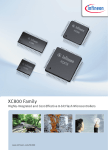
XC800 Family
Guide to using the DALI LightNet tool
AP08104
Application Note
V1.4, 2012-10
Microcontrollers
Edition 2012-10
Published by
Infineon Technologies AG
81726 Munich, Germany
© 2012 Infineon Technologies AG
All Rights Reserved.
LEGAL DISCLAIMER
THE INFORMATION GIVEN IN THIS APPLICATION NOTE IS GIVEN AS A HINT FOR THE IMPLEMENTATION
OF THE INFINEON TECHNOLOGIES COMPONENT ONLY AND SHALL NOT BE REGARDED AS ANY
DESCRIPTION OR WARRANTY OF A CERTAIN FUNCTIONALITY, CONDITION OR QUALITY OF THE
INFINEON TECHNOLOGIES COMPONENT. THE RECIPIENT OF THIS APPLICATION NOTE MUST VERIFY
ANY FUNCTION DESCRIBED HEREIN IN THE REAL APPLICATION. INFINEON TECHNOLOGIES HEREBY
DISCLAIMS ANY AND ALL WARRANTIES AND LIABILITIES OF ANY KIND (INCLUDING WITHOUT
LIMITATION WARRANTIES OF NON-INFRINGEMENT OF INTELLECTUAL PROPERTY RIGHTS OF ANY
THIRD PARTY) WITH RESPECT TO ANY AND ALL INFORMATION GIVEN IN THIS APPLICATION NOTE.
Information
For further information on technology, delivery terms and conditions and prices, please contact the nearest
Infineon Technologies Office (www.infineon.com).
Warnings
Due to technical requirements, components may contain dangerous substances. For information on the types in
question, please contact the nearest Infineon Technologies Office.
Infineon Technologies components may be used in life-support devices or systems only with the express written
approval of Infineon Technologies, if a failure of such components can reasonably be expected to cause the failure
of that life-support device or system or to affect the safety or effectiveness of that device or system. Life support
devices or systems are intended to be implanted in the human body or to support and/or maintain and sustain
and/or protect human life. If they fail, it is reasonable to assume that the health of the user or other persons may
be endangered.
Guide to using the DALI LightNet tool
AP08104
XC83x
Revision History: V1.4 2012-10
Previous Version(s): V1.3
Page
Subjects (major changes since last revision)
–
Updated DALI Control Gear Schematic Part 1; Changed R5 from 1K to 560R
Trademarks
We Listen to Your Comments
Is there any information in this document that you feel is wrong, unclear or missing? Your feedback will help us to
continuously improve the quality of this document. Please send your proposal (including a reference to this document) to:
[email protected]
Application Note
3
V1.4, 2012-10
Guide to using the DALI LightNet tool
AP08104
Table of Contents
Table of Contents
1
Overview . . . . . . . . . . . . . . . . . . . . . . . . . . . . . . . . . . . . . . . . . . . . . . . . . . . . . . . . . . . . . . . . . . . . . . . 5
2
2.1
2.2
2.3
2.4
2.5
2.5.1
2.5.2
2.5.3
Getting started . . . . . . . . . . . . . . . . . . . . . . . . . . . . . . . . . . . . . . . . . . . . . . . . . . . . . . . . . . . . . . . . . . 7
AP08104 Software Package . . . . . . . . . . . . . . . . . . . . . . . . . . . . . . . . . . . . . . . . . . . . . . . . . . . . . . . . . 7
LightNet Installation . . . . . . . . . . . . . . . . . . . . . . . . . . . . . . . . . . . . . . . . . . . . . . . . . . . . . . . . . . . . . . . 8
DALI Control Device Software . . . . . . . . . . . . . . . . . . . . . . . . . . . . . . . . . . . . . . . . . . . . . . . . . . . . . . 13
DALI Control Gear Software . . . . . . . . . . . . . . . . . . . . . . . . . . . . . . . . . . . . . . . . . . . . . . . . . . . . . . . . 13
Hardware Setup . . . . . . . . . . . . . . . . . . . . . . . . . . . . . . . . . . . . . . . . . . . . . . . . . . . . . . . . . . . . . . . . . 13
Setting up the Control Device for LightNet . . . . . . . . . . . . . . . . . . . . . . . . . . . . . . . . . . . . . . . . . . . 13
Setting up the Control Gear . . . . . . . . . . . . . . . . . . . . . . . . . . . . . . . . . . . . . . . . . . . . . . . . . . . . . . . 15
Connecting DALI Master and Slave to the DALI Bus . . . . . . . . . . . . . . . . . . . . . . . . . . . . . . . . . . . 17
3
3.1
3.2
3.3
3.4
3.5
LightNet Tool . . . . . . . . . . . . . . . . . . . . . . . . . . . . . . . . . . . . . . . . . . . . . . . . . . . . . . . . . . . . . . . . . .
Connecting the LightNet tool . . . . . . . . . . . . . . . . . . . . . . . . . . . . . . . . . . . . . . . . . . . . . . . . . . . . . . .
Address Selection . . . . . . . . . . . . . . . . . . . . . . . . . . . . . . . . . . . . . . . . . . . . . . . . . . . . . . . . . . . . . . .
General Control & Status Tab . . . . . . . . . . . . . . . . . . . . . . . . . . . . . . . . . . . . . . . . . . . . . . . . . . . . . . .
Detailed Configuration Command Tab . . . . . . . . . . . . . . . . . . . . . . . . . . . . . . . . . . . . . . . . . . . . . . . .
Memory Access Control Tab . . . . . . . . . . . . . . . . . . . . . . . . . . . . . . . . . . . . . . . . . . . . . . . . . . . . . . .
4
Summary . . . . . . . . . . . . . . . . . . . . . . . . . . . . . . . . . . . . . . . . . . . . . . . . . . . . . . . . . . . . . . . . . . . . . . 24
5
References . . . . . . . . . . . . . . . . . . . . . . . . . . . . . . . . . . . . . . . . . . . . . . . . . . . . . . . . . . . . . . . . . . . . 24
19
19
19
20
21
23
APPENDIX - DALI PHY Board . . . . . . . . . . . . . . . . . . . . . . . . . . . . . . . . . . . . . . . . . . . . . . . . . . . . . 25
APPENDIX - DALI Control Gear Board . . . . . . . . . . . . . . . . . . . . . . . . . . . . . . . . . . . . . . . . . . . . . . 28
Application Note
4
V1.4, 2012-10
Guide to using the DALI LightNet tool
AP08104
Overview
1
Overview
Digital Addressable Lighting Interface (DALI) is a communication protocol for lighting control in buildings. The
interface was first described in the IEC60929 standard for fluorescent lamp ballast, Annex E. The standard was
subsequently updated to include other lighting devices, such as LED, HID, etc., to become IEC-62386. The
complete standard for control interface of electronic control gears was published in June 2009, while the standard
for lighting control devices is scheduled to be published in 2012.
Only a pair of wires are required to form the bus for communication to all devices on a single DALI network. Each
piece of operating equiment with a DALI interface can be communicated with individually. Using a bi-directional
data exchange, a DALI controller can query and set the status of each connected lighting device. As a standalone
system, DALI can be operated with a maximum of 64 devices. Alternatively, DALI can be used as a subsystem via
DALI gateways for connection to building management systems.
Grouped System : Brightness control within large open- plan office, lecture halls or conference
rooms . DALI can provide zoned or localised control of lighting. Control could be offered through
infra-red remote control or a software control with GUI support , or used together as an easy
configuration tool to group loads together. Offering flexibility in customised lighting.
DALI Control Device(s)
(e.g. Control Panel, Remote Controller
, software control with GUI support)
DALI Bus
DALI Power
Supply
DALI Control Gear
(e.g. Lamp)
DALI Control Gear
(e.g. Lamp)
Can connect up to 64
DALI Control Gear
Complex System : Multiple DALI systems can be connected together utilising gateways to building
management systems . Software programs offer more sophisticated programming functionality for
grouped systems , such as scenesetting , timeclock , and partition control .
Building
Management
System
Gateway
DALI Control Device(s)
(e.g. Control Panel, Remote Controller
, software control with GUI support)
Gateway
Gateway
Gateway
DALI
Systems
DALI
Systems
DALI
Systems
DALI Bus
DALI Power
Supply
DALI Control Gear
(e.g. Lamp)
DALI Control Gear
(e.g. Lamp)
Can connect up to 64
DALI Control Gear
Figure 1
DALI system types
Application Note
5
V1.4, 2012-10
Guide to using the DALI LightNet tool
AP08104
Overview
LightNET
DALI configuration SW
for groups and scenes
Power
Supply
XC83x
DALI Slave Board
XC83x
DALI Slave Board
XC83x
SW Stack
XC83x
SW Stack
DALI
PHY
DALI
PHY
Easy Kit as
DALI Master Board
USB /UART
PC Connector
Figure 2
XC83x
SW Stack
DALI BUS
DALI
PHY
Block Diagram for DALI Control Device and Control Gear
Infineon has developed a solution for control gears based on the published IEC standard. The DALI Software
Stack for Control Gear has been designed around the Infineon XC83x devices. ‘LightNet’ has been created to
mimic the basic functions of a lighting control device and can therefore be used to evaluate the software. This
document describes the setup of the LightNet tool.
The following items are required for use with this application note:
•
1x XC836 Easy Kit (to serve as a DALI Control Device; KIT_XC836_EK_V1)
•
1x DALI PHY (KIT_XC822_XC836_DALI)
•
1x XC836 DALI Slave (KIT_DALI_RGB_XC836_DKV1) including DALI Control Gear Software Stack
(AP08102)
•
Infineon DALI LightNet tool
Application Note
6
V1.4, 2012-10
Guide to using the DALI LightNet tool
AP08104
Getting started
2
Getting started
This section is a guide to installing LightNet.
2.1
AP08104 Software Package
This software package consists of the installation package for the LightNet software running on the computer and
a DALI Software for Control Device developed to support the use of the LightNet tool.
The following figures step through the software installation on the user’s computer.
Figure 3
Copying ap08104
Figure 4
Selecting destination location
Application Note
7
V1.4, 2012-10
Guide to using the DALI LightNet tool
AP08104
Getting started
Figure 5
Start the copy process
Figure 6
Copy completed
2.2
LightNet Installation
The LightNet software is designed to provide the control device the facility to send basic DALI commands to the
connected control gear. Installation is only to be performed once, using the file: LightNet_setup_V1_3.exe.
The following figures step through the LightNet tool installation process.
Application Note
8
V1.4, 2012-10
Guide to using the DALI LightNet tool
AP08104
Getting started
Figure 7
LightNet tool installation window
Application Note
9
V1.4, 2012-10
Guide to using the DALI LightNet tool
AP08104
Getting started
Figure 8
LightNet tool license agreement
Figure 9
LightNet tool destination location selection
Application Note
10
V1.4, 2012-10
Guide to using the DALI LightNet tool
AP08104
Getting started
Figure 10
LightNet tool installation start
Figure 11
LightNet tool setup completed
Application Note
11
V1.4, 2012-10
Guide to using the DALI LightNet tool
AP08104
Getting started
Figure 12
Screenshots of LightNet tool
Application Note
12
V1.4, 2012-10
Guide to using the DALI LightNet tool
AP08104
Getting started
2.3
DALI Control Device Software
The DALI Software for Control Device has been developed to support the use of the LightNet tool and can work
on XC836 Easy Kit boards. This software must be downloaded to the XC836 Easy Kit board prior to calling the
LightNet tool. (File: AP0810413_LightNet_XC800Master_code.exe) In addition to control via LightNet, touch pad
control is available.
2.4
DALI Control Gear Software
The DALI Software for Control Gear has been developed on the XC83x devices to support the features specified
in the International Standard IEC-62386 / Part 102 for control gears. This software includes application code for
driving an LED module, supplied with the XC836 DALI Control Gear (KIT_DALI_RGB_XC836_DKV1). Through a
control device, the LightNet software allows DALI commands to be issued to control the brightness of the LED
module attached to the control gear. This software must be downloaded to the XC836 DALI Control Kit. For further
details, please refer to AP08102 DALI Control Gear Software Stack.
2.5
Hardware Setup
The LightNet tool acts as the software for the DALI Control Device, used with the XC836 Easy Kit.
The following sections describe how to setup the LightNet tool to evaluate the DALI protocol.
P C Connection
via US B /UART
DALI Power Supply
1 5 V su p p l y wi th 1 0 0Ω r e si sto r s
to p o we r u p th e DA L I b u s l i n e
Co n tr o l u si n g :
- L i g h tNE T S o ftwa r e
to PC
DALI Master Board
(Control Device )
DALI S lave Board
(Control Gear)
Co mp r i si n g o f:
- K IT_ X C 8 3 6_ E K _ V 1
- K IT_ X C 8 2 2_ X C8 3 6 _ DA L I
Co mp r i si n g o f:
- K IT _DA L I _ RG B _ X C8 3 6 _ DK V 1
Figure 13
Hardware Setup for Infineon Control Device and Control Gear
2.5.1
Setting up the Control Device for LightNet
The XC836 Easy Kit board can be used as the LightNet DALI Control Device, with the following steps:
1. Connect and download the generated hexfile (File:Lightnet_XC800Master.hex) from Section 2.3 into the
XC836 Easy Kit board using XC800 FLOAD in DAVEBENCHTM or KEIL UVision4.
Application Note
13
V1.4, 2012-10
Guide to using the DALI LightNet tool
AP08104
Getting started
Note: To ensure the success of the following procedures, please ensure that the device is configured to User Mode
Diagnostic and COM_SEL settings is set to USB.
Control modes supported :
- LightNET via PC
- Touch Pad control
COM_SEL
This is a default setting
where VDDP is supplied
by 5Vdc from USB port
V_SEL
5V
VIN
3.3V
Touch pads for
command selection
Connect to PC for
LightNET control
Displays the command selected.
- PC control: Displays 8888
- Touch Pad Control: Displays commands
Figure 14
Displays connected devices
- ALL: Broadcast command
- D1: Short Address #0
- D2: Short Address #1
- D3: Short Address #2
Overview for DALI Master (Control Device)
Connections for the DALI PHY Board
DALI PHY
TX
x2
GND RX
VCC
P2.0
P1.5
X1
DALI BUS
H2
H1
DALI PHY
(KIT_XC822 _XC836_DALI)
Connect to DALI Bus
DALI PHY is attached onto (H2 and H1) headers on the XC836 Easy Kit
Figure 15
DALI PHY connection for XC836 Easy Kit
Application Note
14
V1.4, 2012-10
Guide to using the DALI LightNet tool
AP08104
Getting started
METHOD 1: PC Control via LightNet
The LED display shows 8888 whenever LightNet is used.
LightNet functions are described in this document
METHOD 2: TOUCH PAD Control
Upon powering up, default control mode using touch pad control is entered.
Sends Broadcast Address
Sends Short Address 0
Increase brightness
1
2
3
[ALL]
[UP]
[SCENE0]
5
6
[DOWN]
[SCENE1]
8
9
[ON]
[SCENE2]
0
#
[OFF]
[SCENE3]
4
Decrease brigntness
[DEVICE1]
Sends Short Address 1
7
Turns on connected device
[DEVICE2]
Sends Short Address 2
*
Turn off connected device
[DEVICE3]
Figure 16
Goto Scene 0
Goto Scene 1
Goto Scene 2
Goto Scene 3
DALI Control using PC and Touch Pad description
2. The DALI Control Device is now ready to be connected to the DALI bus.
3. User can control the DALI network using LightNet (via PC) and through the Touch Pad available on the XC836
Easy Kit.
2.5.2
Setting up the Control Gear
The DALI Control Gear can be setup with the following steps:
1. Connect the DAP MiniWiggler to the DALI Control Gear as shown in Figure 17. Download the hexfile
(File:AP08102_v1_2_Slave.hex) from Section 2.4 into the DALI Slave Board using XC800 FLOAD in
DAVEBENCHTM or KEIL UVision4.
2. The DALI Control Gear is now ready to be connected to the DALI bus.
Application Note
15
V1.4, 2012-10
Guide to using the DALI LightNet tool
AP08104
Getting started
Power Conn
Connections for programming the DALI
Control Gear using a DAP MINIWIGGLER
5V Supply
(Connector X 3)
1
2 X3
VCC GND
VCC GND
Programming Pin
3
(Connector X 2)
2
1 X2
3
4 2
SPD
(KIT_DALI_RGB_XC836_DKV1)
PC
KIT_DAP_MINIWIGGLER_USB
X3
X2
KIT_DAP_MINWIGGLER_USB
KIT_DALI_RGB_XC836_DKV1
Figure 17
Programming the Control Gear using DAP miniWiggler
Application Note
16
V1.4, 2012-10
Guide to using the DALI LightNet tool
AP08104
Getting started
DALI BUS
Connect to
DALI BUS
2
1
X1
(KIT_DALI_RGB_XC836_DKV1)
DALI BUS Connector
(Connector X 1)
X1
DALI
PHY
DALI Control Gear
(KIT_DALI_RGB_XC836_DKV1)
DALI PHY
Figure 18
Connecting the DALI Control Gear
2.5.3
Connecting DALI Master and Slave to the DALI Bus
The DALI network can be setup with the following steps:
1. To supply power for the DALI bus, connect 100Ω resistors in series to each terminal of a power supply unit
supplying 15VDC. This supplies the DALI bus for the DALI network devices.
2. Connect the DALI Control Device (Master) and Control Gear (Slave) to the DALI bus. This completes the DALI
setup to control the devices using LightNet!
Application Note
17
V1.4, 2012-10
Guide to using the DALI LightNet tool
AP08104
Getting started
POWER SUPPLY UNIT
+15V
GND
100 Ω
100Ω
DALI BUS
Figure 19
Adding 100Ω resistors to Power Supply
POWER SUPPLY
UNIT
+15V
100Ω
GND
100Ω
DALI BUS
DALI Control
Device
DALI Control
Device
PC Connection
via US B / UART
DALI Power Supply
1 5 V su p p l y wi th 1 0 0 Ω r e si sto r s
to p o we r u p th e DA L I b u s l i n e
Co n tr o l u si n g:
- L i g h tNE T S o ftwa r e
to PC
DALI S lave Board
(Control Gear )
DALI Master Board
(Control Device )
Co mp r i si n g o f :
- K IT _ DA L I_ RG B _ X C8 3 6 _ DK V 1
Co mp r i si n g o f:
- K IT _X C 8 3 6_ E K _ V 1
- K IT _X C 8 2 2_ X C 8 3 6_ DA L I
Figure 20
DALI Network Hardware connection
Application Note
18
V1.4, 2012-10
Guide to using the DALI LightNet tool
AP08104
LightNet Tool
3
LightNet Tool
This chapter describes how the LightNet software is organised.
3.1
Connecting the LightNet tool
Once the recommended hardware setup has been completed, LightNet can be used. Figure 21 shows how to
connect to the LightNet tool.
Note: The LightNet tool cannot be activated if the recommended setup has not been completed as described; i.e.
the XC836 Easy Kit is not connected, or the BMI is incorrectly selected.
“RED” indicates that
board is not connected.
“GREEN” indicates that
board is connected.
Clicking on “Connect”
initiates connection to
LightNet tool
Clicking on “Disconnect”
initiates disconnection
from LightNet tool
Figure 21
Connecting the Board
3.2
Address Selection
LightNet supports 3 types of DALI addressing:
•
•
•
Broadcast
Short Address
Group Address
The user decides the type of addressing to be sent with each command by selecting from the available options.
For Group Address, the user is required to add the group address to the detailed configuration settings tab, as
shown in Chapter 3.4.
Broadcast Address:
Fixed address of 0xFF is
sent with commands.
NOTE:
1, Steps to adding group address
and programming of short address
can be found in Detailed
Configuration tab.
Short Address:
User selectable short
address range from 00 to
63.
2. This selection allows user
commands to be addressed with
the various supported address
types listed.
Group Address:
Group setting needs to be
added by user. Supports
range from 00 to 15.
Figure 22
Address Selection
Application Note
19
V1.4, 2012-10
Guide to using the DALI LightNet tool
AP08104
LightNet Tool
3.3
General Control & Status Tab
This section describes the general device control and status functions.
ON & Step Up:
Turns on device if current state
is OFF. Otherwise, set power
level 1 step higher immediately
without fading.
Step Down & OFF:
Turns off device if current state
is minimum level. Otherwise,
set power level 1 step lower
immediately without fading.
Up :
Dim up 200ms using the
selected Fade Rate. No change
if power level is already at
Maximum.
Maximum:
Sets device to Maximum level
without fading. Turns on
device, if current state is OFF.
Step Up:
Set power level 1 step higher
immediately without fading.
OFF:
Turns off device.
Step Down:
Set power level 1 step lower
immediately without fading.
Minimum:
Sets device to Minimum level
without fading. Turns on
device, if current state is OFF.
Send Direct ARC:
Sends Direct ARC level command to device. User entry for
desired ARC level to be sent
Down:
Dim down 200ms using the
selected Fade Rate. No change if
power level is already at
Minimum.
Steps to send direct ARC commands:
1. Enter user desired ARC level.
2. Click on “Send Direct ARC” to send command to device.
Figure 23
Light Control
Control Gear:
Indicates if connected
control gear is functional.
Status: OK or NO
Fade Running?:
Status: YES or NO
Reset State?:
Indicates if device is in
reset state.
Status: YES or NO
Get Status:
Click on this to obtain
current device status
Lamp Failure:
Indicates if connected lamp
has failure.
Status: YES or NO
Missing Short Addr.?:
Indicates if device has
short address missing.
Status: YES or NO
Lamp Arc Power:
Indicates power status.
Status: ON or OFF
Power Failure?
Indicates if power failure has
occurred. If no failure, it
means that a "RESET" or an
arc power control command
has been received since last
power-on.
Status is YES or NO
Limit Error?
Indicates if last requested
arc power level is between
MIN and MAX LEVEL or
OFF
Status is YES or NO
Actual Level:
Indicates current power level
of connect device
Figure 24
Device Type:
Indicates which device is
connected.
0: Fluorescent lamps
6: LED modules
Fade Rate:
Range: 1 to 15
Fade Time:
Range: 0 to 15
Device Status
Application Note
20
V1.4, 2012-10
Guide to using the DALI LightNet tool
AP08104
LightNet Tool
Scenes:
Supports 16 scenes.
User to select desired
scene to enter.
Go To Scene:
Click button to jump
to the selected
Scene.
Figure 25
Go to scenes
3.4
Detailed Configuration Command Tab
This section describes the options in the configuration settings.
Group #:
Selects group for selected device to join or
remove.
Program Short Addr:
Programs user selected short address to
connected device.
Range: 0 to 63
Steps to Join / Remove group:
1. Select the desired group from the drop
down list provided.
2. Click on the radio button for the desired
action. (Join / Remove)
Steps to Program Short Address:
1. Select from drop down list desired
short address.
2. Click on Program button, Once
completed, new setting takes effect.
Scene # / Level:
Selects the scene for selected device to be
set or removed. To set the scene level, user
can enter desired scene level in the level
field provided.
Time / Rate:
Selects the device fade time / rate.
Fade Time Range: 0 to 15
Fade Rate Range: 1 to 15
Steps to select Fade Control Settings
:
1. Select from drop down list. Once
setting, new setting takes effect.
Steps to Set / Remove Scene info:
1. Select the desired scene from the drop
down list provided.
2. Enter the desired level in the Level field.
Skip this step if intention is to remove
scene.
3. Click on the radio button for the desired
action. (Set / Remove)
Device Enable Type:
Set the device enable type.
Supported types: 0 and 6.
Steps to enable type settings
:
1. Select from drop down list. Once setting,
new setting takes effect.
Figure 26
Power Control Settings:
Sets the desired power setting for
selected device. Supports following
setting:
- Maximum level
- Minimum level
- System Failure level
- Power ON level.
Reset:
Reset selected device
to reset condition.
Steps to Set power settings:
1. Select the type of power setting to be
changed.
2. Enter the desired level in the Level
field.
3. Click on the Set to activate setting.
4. The new settings will only be
programmed to the flash upon “OFF”
selection in the Lights Control tab.
Configuration Settings
Application Note
21
V1.4, 2012-10
Guide to using the DALI LightNet tool
AP08104
LightNet Tool
Physical Min. Level :
Indicates the physical minimum
level of the selected device .
Refresh! :
Click on this to refresh
data in window
Maximum Level :
Indicates the maximum level of
the selected device.
Scenes :
Indicates the power level
information from Scene 0
to 15
Minimum Level :
Indicates the minimum level of
the selected device.
Power ON Level :
Indicates the power on level
when turn on of the selected
device.
System Failure Level :
Indicates the system failure level
of the selected device.
Group :
Indicates the group(s) that
selected device belongs
to.
Versioning :
Indicates the version number
Figure 27
Device Information
Application Note
22
V1.4, 2012-10
Guide to using the DALI LightNet tool
AP08104
LightNet Tool
3.5
Memory Access Control Tab
This section describes the options for memory access feature.
Memory Bank Window
This shows the contents of the memory banks.
Select the required memory contents for read or write.
Clicking this window opens up the Memory Access
Input Dialog.
Factory Settings Description
Describes the memory settings
supported for Bank 0 and 1
Retrieve Factory Settings
This option retrieves the memory bank contents settings.
Note: This operation takes a few seconds to complete.
Figure 28
Memory Bank Window
Address (Hex)
Displays the address of the user selected
memory cell from the Memory Bank Window.
Memory bank Selection
Selects Memory Bank 0 or 1.
Read Button
Executes the read command
Write ButtonSelection
Executes the write memory
command
Content (Hex)
User entered content for the selected memory cell.
This operation is supported for memory bank 1
when memory bank 1 lock byte is “ 55h” in
accordance with IEC62386
Figure 29
Memory Input Dialog
Application Note
23
V1.4, 2012-10
Guide to using the DALI LightNet tool
AP08104
Summary
4
Summary
Infineon’s LightNet tool models the function of a lighting control device, controlling DALI control gears. This
document demonstrates how easy the tool is to use, to evaluate a DALI system.
5
References
[1]
IEC 62386 Digital addressable lighting interface; Part 101: General requirements - System (Edition 1.0, 200906)
[2]
IEC 62386 Digital addressable lighting interface; Part 102: General requirements - Control gear (Edition 1.0,
2009-06)
[3]
AP08102 DALI Control Gear Software Stack
[4]
XC82x User Manual 1.1 Hardware Manual Easy Kit XC822-TSSOP16 board V1.0
[5]
XC83x User Manual 1.0 Hardware Manual Easy Kit XC836-TSSOP board V1.0
Application Note
24
V1.4, 2012-10
Guide to using the DALI LightNet tool
AP08104
References
APPENDIX - DALI PHY Board
Infineon DALI PHY circuit construction to support device evaluation within a typical DALI network, using the XC836
Easy Kit board. This following figure shows the schematic for a DALI PHY circuit construction that can be used
with the XC822 Easy Kit board.
Note: The DALI PHY board design supports a DALI bus level from 14.5V to 22.5V. The values of R1 and R4 can
be adjusted to support a wider DALI bus voltage range if required.
Connect to DALI BUS
Connect to MCU
DALI PHY
Note:
IFX DALI PHY Board connectors ensure
usage configurability .
IFX DALI PHY BOARD CONNECTORS
Depending on DALI Control Gear
Software stack settings, the DALI_TX/_RX
pins can be connected via jumpers to the
corresponding pins on the Easy Kit
connectors .
Figure 30
DALI PHY Board Schematics
Application Note
25
V1.4, 2012-10
Guide to using the DALI LightNet tool
AP08104
References
Figure 31
Infineon DALI PHY Board and Layout
Table 1
Bill of Material for DALI PHY Circuit
Item
Reference
Value
Device
Package
Description
1
B1
MB2S
MB2S
SOIC-4
Bridge Rectifier
2
C1
1u / 25V
C-EUC1210
C1210
Capacitor
3
D2
BAS16
DIODE-SOD323-R
SOD323-R
Diode
4
D3
BZX384-2V7
DIODE-SOD323-R
SOD323-R
Diode
5
IC1
SFH6156-2
SFH6156
SFH
5.3 kV TRIOS High Reliability
Optocoupler
6
IC2
SFH6156-2
SFH6156
SFH
5.3 kV TRIOS High Reliability
Optocouplerstor
7
Q1
BC817-25W
BC81725WSMD323
SOT323
NPN Transistor
8
R1
10R
R-EU-R0603
R0603
Resistor
9
R2
0R
R-EU-R0603
R0603
Resistor
10
R3
0R
R-EU-R0603
R0603
Resistor
11
R4
11k
R-EU-R0603
R0603
Resistor
12
R5
324R
R-EU-R0603
R0603
Resistor
13
R6
4R7
R-EU-R0603
R0603
Resistor
14
R7
1k21
R-EU-R0603
R0603
Resistor
15
R8
3k16
R-EU-R0603
R0603
Resistor
16
X1A
MKDSN1,5/25,08
MKDSN1,5/2-5,08
MKDSN1,5/
2-5,08
MKDSN 1,5/2-5,08 Printklemme
17
X1B
2x1
PINHD-1X2
1X02
Pin Header
18
X2
4x1
PINHD-1X4
1X04
Pin Header
Application Note
26
V1.4, 2012-10
Guide to using the DALI LightNet tool
AP08104
References
Table 1
Bill of Material for DALI PHY Circuit
Item
Reference
Value
19
H1
20
H2
Application Note
Device
Package
Description
SAMTEC SSQ-1- PINHD-1X14
14-03-S-S
1X14
Pin Header
SAMTEC SSQ-1- PINHD-1X14
14-03-S-S
1X14
Pin Header
27
V1.4, 2012-10
Guide to using the DALI LightNet tool
AP08104
References
APPENDIX - DALI Control Gear Board
Schematic for KIT_DALI_RGB_XC836_DKV1
Figure 32
Control Gear Board Schematics - Part 1
Application Note
28
V1.4, 2012-10
Guide to using the DALI LightNet tool
AP08104
References
Figure 33
Control Gear Board Schematics - Part 2
Application Note
29
V1.4, 2012-10
Guide to using the DALI LightNet tool
AP08104
References
X1
DALI Control Gear
(KIT_DALI_RGB_XC836_DKV1)
FRONT
Figure 34
BACK
Control Gear Board Layout
Application Note
30
V1.4, 2012-10
w w w . i n f i n e o n . c o m
Published by Infineon Technologies AG