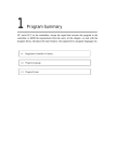
1
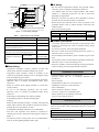
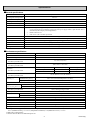
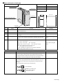
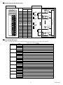
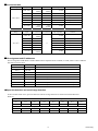
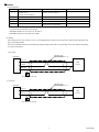
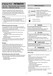
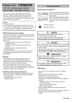
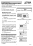
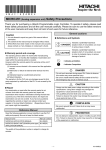
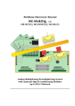
EH-150 series PLC
HITACHI
EH-RTD8
Resistance Temperature Detective
input module
Instruction manual
Safety precautions
Definitions and Symbols
!
Thank you for purchasing a Hitachi Programmable Logic
Controller. To operate it safely, please read this instruction
manual and all the user manuals carefully. Please be sure to
use the latest versions of user manuals and keep them at hand
of end users for future reference.
!
DANGER
Indicates a potentially hazardous situation
which, if not avoided, can result in serious
injury or death.
CAUTION
Indicates a potentially hazardous situation
which, if not avoided, can result in minor
to moderate injury, or serious damage of
product.
: Indicates Prohibition
Caution
1. All rights reserved.
2. The content of this manual may be changed without notice.
3. While efforts have been made on this manual to be
accurate, please contact us if any mistake or unclear part is
found.
!
: Indicates Compulsion
!
DANGER
- Do not touch terminals while power ON. There is a danger of
electric shock and/or injury.
- Be sure to install external safety devices outside of the PLC
like emergency stop circuit or interlock circuit.
Warranty period and coverage
The warranty period is within 18 months after manufacturing
date (MFG NO.) or 12 months after installation.
Examination and repair within the warranty period is covered.
However within the warranty period, the warranty will be
void if the fault is due to;
(1) Incorrect use from instructed in this manual and the
application manual.
(2) Malfunction or failure of external other devices than
this unit.
(3) Attempted repair by unauthorized personnel.
(4) Natural disasters.
The warranty is for the PLC only, any damage caused to third
party equipment by malfunction of the PLC is not covered by
the warranty.
!
CAUTION
- Be sure that the rated voltage matches the power supply
voltage of the unit. Otherwise, there is a danger of breakdown
and/or injury and/or fire.
- Only qualified personnel shall carry out wiring work.
Otherwise, there is a danger of breakdown and/or injury and/or
fire.
COMPULSION
- Be sure to ground the unit. Otherwise, there is a danger of
electric shock and/or malfunction.
PROHIBITION
- Do not attempt to modify nor disassemble the unit. There is a
danger of breakdown and/or injury and/or fire.
Repair
Any examination or repair after the warranty period is not
covered. And within the warranty period any repair and
examination which results in information showing the fault
was caused by any of the items mentioned above, the repair
and examination cost are not covered. If you have any
questions regarding the warranty or repair cost, please contact
your supplier or the local Hitachi Distributor. (Depending on
failure part, repair might be impossible.)
Mounting
- Mount the PLC on a metal plate and install in a cabinet as
follows.
- Be sure to ground the cabinet and the metal plate, otherwise
there is a risk of malfunction.
- Install the PLC as described in user manual.
- Take appropriate measures when the PLC system installed in
locations:
Influenced easily due to noise or static electricity or other
forms of noise.
Under strong electromagnetic field.
Close to power supplies.
- Be sure to tighten mounting screws, terminal screws and
connector screws.
- Be sure to check that devices with lock mechanism, such as an
expansion cable or terminal blocks, are locked properly.
Ordering spare parts and inquiries
Please contact your local suppliers for ordering products/spare
parts or any inquiries with providing the following
information.
(1) Product name
(2) Manufacturing number (MFG NO.)
(3) Details of failure
1
NJI-613 (X)
I/O Wiring
Enclosure
Metal plate
- Be sure that the input/output matches the specified voltage.
Otherwise, there is a danger of breakdown and/or fire.
- Use shielded cable for relay outputs modules, and connect
shields to a functional ground for one side or both sides
depending on applications.
- Route the AC power line and I/O lines separated as much as
possible. Do not route both cables in a same duct.
- Route the I/O lines and data lines as close as possible to the
grounded surfaces such as cabinet elements, metal bars and
cabinets panels.
- Refer to the following table.
Basic Unit
Grounding
CPU
AC
Expansion Unit
AC
Power
supply
Net filter
AC
Earth leakage
Breaker
Grounding
Insulation transformer (recommended)
Figure 1
Table 1
Power wiring example
Electric wire for wiring
Specifications of the net filter
Item
Type
22-14 AWG
Copper
Single/twisted wire available
Common precautions
250
Rated current (A)
- Use proper cable ferrules for terminals. Using improper cable
ferrules or connecting bare wires to terminals directly might
result in fire.
- Do not turn on power, if the unit appears damaged.
- Be sure to check all the field wiring before PLC power on.
Otherwise, there is a risk of fire.
- Do not attempt to disassemble, repair or modify any part of the
PLC.
- Do not pull on cables or bend cables beyond their natural limit.
Otherwise, there is a risk of breaking of wire.
- Keep PLC modules in their boxes during storage and transport.
- Check carefully your PLC program before operation.
5
Withstand voltage (V)
1,500
(between Terminal and case)
Insulation resistance (MΩ)
(500V DC, 1min., between terminal and case)
(dB)
Material
Spec.
Rated voltage (V AC)
Attenuation characteristic
Size
0.5 to 30 MHz
0.15 to 30 MHz
Terminal
tightening
torque
9in. –1bs
(1.02 Nm)
100 (min.)
Common mode
more than 40dB
Differential mode
more than 40dB
Power Wiring
- Appropriate emergency circuitry, interlock circuitry and
similar safety measures should be added to the system.
- Appropriate safety measures should be included in the
system for unexpected breaking of wire or malsignal caused
from instantaneous power failure.
- Applied voltage must be in the range specified in the manual.
Otherwise, there is a danger of breakdown and/or injury
and/or fire.
- Install an external earth leakage breakers to avoid short
circuit accident.
- In case of the following operations, turn off power.
Otherwise, there is a danger of breakdown and/or injury
and/or fire.
Mounting or dismounting CPU and I/O modules.
Assembling cabinet or machine including PLC.
Wiring.
- Install net filter specified in Table 1 or similar. The input and
output cable of the net filter should be separated as much as
possible. Be sure to ground the net filter.
- A shielded and insulated transformer is recommended.
- The basic and expansion unit should be connected to
common power source and powered up together as shown in
Figure 1.
- To install an arrester in each power wire is recommended in
order to prevent lightning damage and/or injury.
Installation environment
Avoid the following locations to install the PLC.
- Excessive dusts, salty air, or conductive materials (iron
powder, etc.)
- Direct sunlight.
- Temperature less than 0○C or more than 55○C
- Humidity less than 5% or more than 95%.
- Dew condensation.
- Direct vibration or impact to the unit.
- Corrosive, explosive or combustible gases.
- Water, chemicals or oil splashing on the PLC.
- Close to noise emission devices.
Reference Manual
Read the following application manual carefully depends on
series to use the PLC safely and properly. Be sure to keep the
latest version.
Manual name
Manual No.
EHV-CPU APPLICATION MANUAL
NJI-481* (X)
EHV-150 APPLICATION MANUAL
NJI-281* (X)
* The alphabet between 481 and (X) means version (A, B...) and
the space means the first edition.
2
NJI-613 (X)
Specifications
General specifications
Item
Specifications
Operating ambient temperature
0 to 55°C
Storage ambient temperature
-10 to 75°C
Operating ambient humidity
5 to 95 % RH (no condensation)
Storage ambient humidity
5 to 95 % RH (no condensation)
Vibration resistance
Conforms to IEC 60068-2-6
○
Noise resistance
○
○
Insulation resistance
Noise voltage 1,500 Vpp Noise pulse width 100 ns, 1µs
(Noise created by the noise simulator is applied across the power supply module’s input terminals. This is
determined by this company’s measuring method.)
Based on IEC61131-2
Static noise: 3,000 V at metal exposed area
20 MΩ or more between the AC external terminal and case ground (FE) terminal (based on 500 V DC)
Dielectric withstand voltage
1,500 V AC for 1 minute between the AC external terminal and case ground (FE) terminal
Grounding
Class D grounding (ground with power supply module)
Usage environment
No corrosive gases, no excessive dust
Structure
Open, wall-mount type
Cooling
Natural air cooling
Performance specification
Item
Specification
Type
EH-RTD8
Supported RTD type
PT100 / PT1000 (3-wire or 2-wire)
Number of channel
Selectable by the DIP switch
6 (3-wire) or 8 (2-wire)
Temperature range
Selectable by the DIP switch
-200 to 850°C or -40 to 60°C
○
Resolution
Selectable by the DIP switch
C conversion
-200 to 850○C : 0.1°C
-40 to 60○C : 0.02°C
Conversion time
Selectable by the DIP switch
Accuracy *1
I/O assignment
F conversion
-328 to 1562○F : 0.1○F
-
PT4 compatible
-60 to 410○C : 15 bits
-25 to 45○C : 15 bits
1.6s (all channels) or 0.5s (all channels)
Max. ±0.5°C (measured temperature under 380°C)
Max. ±0.8°C (measured temperature over 380°C)
±0.01% / ○C (FS)*2 (±0.1°C / °C )
0.18mA
LED blinking at error channel
H7FFF
Standard accuracy (25○C)
Temperature coefficient
Measurement current
Diagnostic error
LED
(Wire breaking detection) Conversion value
Input filter
Selectable by the DIP switch
Warm-up time *3
Isolation
Channel to internal circuit
Between channels
Weight
External wiring
Internal current consumption (5 V DC)
External power
Wiring
○
None or moving average 16 times
1 minute
Photo coupler
Not isolated
Approximately 0.15 kg
Removable terminal (M3)
Max. 300mA
None
Twisted shield cable, wiring resistance Max. 5Ω (Max. 100m of 22AWG)
Selectable by the DIP switch
X8W or X4W (PT4 compatible mode)
*1 Example : Measuring under 380°C in ambient temperature 35°C.(under noise-free environment)
0.5°C (standard accuracy) + 0.1°C/°C (temperature coefficient) × 10 (difference to 25°C) = ±1.5°C
*2 Full scale is -200 to 850°C.
*3 It is the time for data to be stable after power on.
3
NJI-613 (X)
Name and function of each part
Name and function of each part
1] Lock button
5] LED display
Model name
EH-RTD8
Weight
Approx. 0.15 kg
Consumption current
Approx. 300 mA
Dimensions (mm (in.))
30 (1.18)
95 (3.74)
2] I/O cover
100 (3.94)
4] Mode setting DIP switch
3] Terminal
No.
Name
Function
1]
Lock button
Press this button to dismount. Module can be fixed firmly by a screw of
M4 × 10 mm (0.39 in.).
2]
I/O cover
This is the cover attached to the terminal block area.
3]
Terminal
This is the terminal block for connecting input signals. The terminal block is
removable.
4]
Mode setting DIP switch
These switches are to set wiring type, temperature range, input filter,
conversion time, temperature unit, EH-PT4 compatible mode and sensor
type.
5]
LED display
The status of module and input signal are indicated in this LED.
OK : Green : Normal status
2W : Green : 2-wire mode
Off : 3-wire mode
AMB : Green : -40 to 60○C mode
Off : -200 to 850○C mode
HS : Green : High speed conversion time (0.5s)
Off : Normal conversion time (1.6s)
0 to 7 : Blinking red : Open-wire or out-of-range is detected in
corresponding channel number (0.5s cycle)
Item
Explanation of operation
Detail explanation
Remarks
Refer to Mode setting DIP
switch.
Refer to Mode setting DIP
switch.
Remarks
The module receives input signals from outside.
The CPU module verifies the status of the installed module and if the I/O
assignment information matches that contained in the user program, the input
information is received according to the contents of the user program.
Terminal block
The screws for the terminal block are M3 screws. Use a crimp terminal that fits the
screw diameter. The maximum thickness of the cable should be only up to 0.75
mm2. (Use 0.5 mm2 cable when two crimp terminals are attached to the same
terminal.)
The recommended crimp terminal is indicated below.
6
6
(Recommended)
Handle very carefully since
cable could be detached
when screw is loose.
Unit : mm
4
NJI-613 (X)
Terminal layout and internal circuit
Terminal layout
Internal circuit
OK 2W AMB HS
0 1 2 3
4 5 6 7
PT INPUT
EH-RTD8
①
⑩
②
⑪
Signal name
2-wire
3-wire
①
A0
A0
②
A1
b0
③
B2・B3
B1
④
A4
A2
⑤
A5
b2
⑥
B6・B7
B3
⑦
NC
A4
⑫
⑧
NC
b4
⑬
⑨
NC
B5
⑩
B0・B1
B0
③
④
⑤
⑭
⑪
A2
A1
⑮
⑫
A3
b1
⑯
⑬
B4・B5
B2
⑭
A6
A3
⑮
A7
b3
⑯
NC
B4
⑰
NC
A5
⑱
NC
b5
⑥
⑦
⑧
⑰
⑨
⑱
A0
A0
B0・1
B0
A1
b0
Internal circuit
No.
A6
B6・7
A7
A5
B5
b5
Mode setting DIP switch
Please set the DIP switch before use. If change the DIP switch while power on, the setting is same as before.
[ Black part is factory setting ]
No.
SW1-1
Setting
1
OFF
Function
Wiring type
3-wire
SW1-2
ON
2
OFF
2-wire
Temperature range
-200 to 850○C, ○F conversion: -328 to 1562○F, EH-PT4 compatible:-60 to 410○C
SW1-3
ON
3
OFF
-40 to 60○C, ○F conversion: -328 to 1562○F , EH-PT4 compatible: -25 to 45○C
Input filter
None
SW1-4
ON
4
OFF
16 times moving average
Conversion time
1.6s
ON
5
OFF
ON
6
OFF
ON
7
OFF
8
OFF
0.5s
Temperature unit
○
C
○
F
EH-PT4 compatible mode
Disable
Enable
For system use
Set always OFF
For system use
Set always OFF
9
OFF
Sensor type
Pt1000
SW1-5
SW1-6
SW1-7
SW1-8
SW2
ON
Pt100
5
NJI-613 (X)
Conversion table
Range
○
Input
C conversion
F conversion
PT4 compatible
Remarks
Under -200○C
-32768
(H8000)
-32768
(H8000)
H7FFF
-200○C
-2000
-3280
H7FFF
Measurement minimum
-60○C
-600
-760
HF666
PT4 range minimum
○
○
-200 to 850 C
0C
0
320
H0000
410○C
4100
7700
H4199
PT4 range maximum
850 C
8500
15620
H7FFF
Measurement maximum
Over 850○C
32767
(H7FFF)
32767
(H7FFF)
H7FFF
○
Range
○
○
Input
C conversion
○
F conversion
PT4 compatible
Remarks
Under -40○C
-32768
(H8000)
H7FFF
-40○C
-4000
H7FFF
Measurement minimum
HD800
PT4 range minimum
○
-25 C
-2500
0○C
0
45○C
4500
H4800
PT4 range maximum
60○C
6000
H7FFF
Measurement maximum
Over 60○C
32767
(H7FFF)
H7FFF
-40 to 60○C
*1
H0000
*1: Same as -200 to 850○C.
I/O assignment and I/O addresses
The I/O assignment of EH-RTD8 is X8W. If EH-PT4 data compatible mode is enabled, it is X4W, which is same as EH-PT4.
Data table is listed as below.
Outside IO number
Remarks
CH
WX**0
CH0 data
WX**1
CH1 data
WX**2
CH2 data
WX**3
CH3 data
WX**4
CH4 data
When EH-PT4 compatible mode is enabled, data is always 0.
WX**5
CH5 data
When EH-PT4 compatible mode is enabled, data is always 0.
WX**6
CH6 data
When EH-PT4 compatible or 3-wire mode is enabled, data is always 0.
WX**7
CH7 data
When EH-PT4 compatible or 3-wire mode is enabled, data is always 0.
■Open-wire detection and out-of-range detection
If CPU module is EHV series, open-wire detection and out-of-range detection are monitored in the data WEX**0.
WEX**0
Out-of-range detection (ON when out of the range.)
bit 7
bit 6
bit 5
bit 4
bit 3
bit 2
bit 1
bit 0
CH7
CH6
CH5
CH4
CH3
CH2
CH1
CH0
Open-wire detection (ON when open-wire is detected.)
bit 15
bit 14
bit 13
bit 12
bit 11
bit 10
bit 9
bit 8
CH7
CH6
CH5
CH4
CH3
CH2
CH1
CH0
6
NJI-613 (X)
Caution
(1) LED indication
LED
OK
2W
Off
- No power supplied.
- Module error.
(Contact your local supplier.)
Blinking
Module error.
(Contact your local supplier.)
3-wire mode.
-
○
-200 to 850 C.
1.6s conversion time.
Normal operation.
AMB
HS
0 to 7
Lighting
Normal operation.
2-wire mode.
- Wire is disconnected.
- Input signal is out of the range.
-40 to 60○C.
0.5s conversion time.
-
* If no sensor is connected, open-wire is detected, LED of corresponding input number is blinking. The blinking can be avoided
by short between terminals in each channel.
[Intended terminals in 3-wire input] A*, B* and b*
[Intended terminals in 2-wire input] A* and B*
(2) Wiring
Since analog signal is very sensitive, be sure to use shielded cable in order to protect from noise, and route the cable apart from
other power/signal cables.
Be sure to ground the shield at one end basically. But grounding at both ends or no grounding can be more effective depending
on system environment.
3-wire input
Shielded cable
(Twisted cable)
EH-RTD8
A0 to A5
RTD
(3-wire)
b0 to b5
B0 to B5
Shielded
Grounding at the one end
2-wire input
Shielded cable
(Twisted cable)
EH-RTD8
A0 to A7
RTD
(2-wire)
B0 to B7
Shielded
Grounding at the one end
7
NJI-613 (X)