1
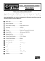
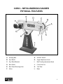
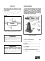
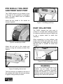
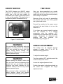
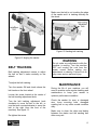
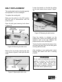
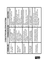
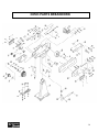
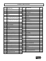
CX503 METAL WORKING BELT SANDER User Manual TABLE OF CONTENTS General Safety Instructions..................................................................................... 3 Specific Safety Instructions..................................................................................... 4 Features.................................................................................................................. 5 Physical Features ................................................................................................... 6 Set-Up..................................................................................................................... 7 Un-Packing & Inventory .......................................................................................... 7 Proper Grounding ................................................................................................... 8 Securing to Shop Floor ........................................................................................... 9 Mounting the Sander............................................................................................... 9 Eye Shield, Tool Rest and Spark Trap.................................................................... 10 Dust Collection........................................................................................................ 10 ON/OFF Switch....................................................................................................... 11 Test Run ................................................................................................................. 11 Angle Adjustment.................................................................................................... 11 Belt Tracking ........................................................................................................... 12 Maintenance ........................................................................................................... 12 Belt Replacement.................................................................................................... 13 Wiring Diagram ....................................................................................................... 14 Trouble Shooting..................................................................................................... 15 Parts Breakdown..................................................................................................... 16 Parts List................................................................................................................. 17 Warranty ................................................................................................................. 18 2 GENERAL SAFETY INSTRUCTIONS FOR MACHINES Extreme caution should be used when operating all power tools. Know your power tool, be familiar with its operation, read through the user manual, and practice safe usage procedures at all times. ALWAYS read and understand the user manual before operating the machine. CONNECT your machine ONLY to the matched and specific power source. ALWAYS wear safety glasses respirators, hearing protection and safety shoes, when operating your machine. DO NOT wear loose clothing or jewelry when operating your machine. A SAFE ENVIRONMENT is important. Keep the area free of dust, dirt and other debris in the immediate vicinity of your machine. BE ALERT! DO NOT use prescription or other drugs that may affect your ability or judgment to safely operate your machine. DISCONNECT the power source when changing drill bits, hollow chisels, router bits, shaper heads, blades, knives, or making other adjustments or repairs. NEVER leave a tool unattended while it is in operation. NEVER reach over the machine when the tool is in operation. ALWAYS keep blades, knives and bits sharpened and properly aligned. ALL OPERATIONS MUST BE performed with the guards in place to ensure safety. ALWAYS use push sticks and feather boards to safely feed your work through the machine and clamp the work-piece (when necessary) to prevent the workpiece from any unexpected movement. ALWAYS make sure that any tools used for adjustments are removed before operating the machine. ALWAYS keep the bystanders safely away while the machine is in operation. NEVER attempt to remove jammed cutoff pieces until the saw blade has come to a full stop. 3 CX503 – METALWORKING SANDER SPECIFIC SAFETY INSTRUCTIONS This machine is designed and intended for use by properly trained and experienced personnel only. If you are not familiar with the proper use of metal sanders, do not use this machine until proper training and knowledge has been obtained. Keep guards in place. Belt guards must be kept in place and in working order all the times to ensure safety. Use proper respirator. Always use proper respirator while operating this sander. Wear proper apparel. Loose clothing, gloves, neckties, bracelets, or other jewelry may get caught in moving parts. Non-slip footwear is recommended. Wear protective hair covering to contain long hair. Always use safety glasses. For the safety of your eyes, safety glasses should be used while operating the lathe. Hearing protection. Always wear proper hearing safety equipment while operating this sander. Dust collection system. Do not operate this sander without connecting to a proper dust collection system. Make sure to use a system rated for metal dust collection. Flammable materials. Sanding metal causes sparks. Make sure there is no flammable material close to the sander while operation. Grasp the stock with both hands. Feed it into the machine with light pressure against the direction of rotation of the belt. Do not sand pointed or tapered stock with the point facing the feed direction and never sand more than one piece of stock at a time. Remove adjusting keys and wrenches. Remove all the tools used for adjustment before turning the machine on. Be careful. Do not place your hands close to the sanding belt while the machine is running. Maintain sander with care. Perform machine inspection and maintenance service regularly. Turn the power OFF. Before making any adjustments, make sure the switch is in the “OFF” position and the cord is un-plugged from the power outlet. Make sure you have read and understood all the safety instructions in the manual and you are familiar with your metal sander, before operating it. If you fail to do so, serious injury could occur. WARNING The safety instructions given above can not be complete because the environment in every shop is different. Always consider safety first as it applies to your individual working conditions. 4 CX503 – METALWORKING SANDER FEATURES MODEL CX503 – METALWORKING SANDER As part of the growing line of Craftex metalworking equipment, we are proud to offer the CX503 a Metalworking Sander. The Craftex name guarantees Craft Excellence. By following the instructions and procedures laid out in this user manual, you will receive years of excellent service and satisfaction. The CX503 is a professional tool and like all power tools, proper care and safety procedures should be adhered to. Motor Type ..................................... TEFC Motor Horsepower .......................... 2-HP Motor Phase & Voltage................... Single Phase 220-Volt Amperage .......................................10-Amps Bearings ......................................... Sealed and Permanently Lubricated Cycle & RPM .................................. 60 Hertz and 3400 RPM Sanding Belt Size ........................... 3” x 78” Contact Wheel Diameter ................ 7-3/4” (195mm) Contact Wheel Surface................... Rubber Sanding Belt Speed........................35 m/s Sanding Belt Tilt ............................. 0 – 60-degree Height ............................................. 19” Width .............................................. 27” Length ............................................ 44” Weight ............................................ 158 lbs, 72 Kg Warranty ......................................... 3-Year 5 CX503 – METALWORKING SANDER PHYSICAL FEATURES A. Sanding Belt G. ON/OFF Switch B. Eye Shield H. Angle Adjustment Lever C. Eye Shield Bracket I. Belt Tracking Adjustment Knob D. Belt Guard J. Front Dust Port E. Belt Guard Securing Knob K. Tool Rest F. Motor L. Base 6 SETUP Before setting up your machine you must read and understand the instructions given in this manual. When setting up your machine, you will want to find an ideal spot where your metalworking sander will be located most of the time. UNPACKING To ensure safe transportation this machine has been properly packaged and shipped completely in a crate. When unpacking, carefully inspect the crate for any damage. Open the crate and check that the machine and parts are in good condition. Figure-1 Minimum workspace for CX503 Figure-2 Inventory WARNING CX503 is a heavy machine. Do not overexert yourself. Use a fork truck or other mechanical devices for safe moving. LIST OF CONTENTS QTY A. Metalworking Sander ...................... 1 B. Stand ............................................... 1 C. Front Dust Port................................. 1 WARNING D. Tool Rest ......................................... 1 While doing inventory, if you can not find any part, check if the part is already installed on the machine. Some of the parts come preassembled on the machine. E. Eye Shield........................................ 1 F. Sander Angle Adjustment Lever ...... 1 G. Hardware..............................One Bag 7 PROPER GROUNDING Grounding provides a path of least resistance for electric current to reduce the risk of electric shock. CX503 is equipped with a 220-V single phase motor. To prevent electrical hazards, have a qualified electrician ensure that the line is properly wired. This sander is for use on a normal 220 volt circuit. Make sure that the machine is connected to an outlet having the same configuration as the plug. If an adaptor plug is used, it must be attached to the metal screw of the receptacle. WARNING Improper connection of the equipmentgrounding conductor can result in a risk of electric shock. Check with a qualified electrician if you are in doubt as to whether the outlet is properly grounded. It is strongly recommended not to use extension cords with your CX503. Always try to position your machine close to the power source so that you do not need to use extension cords. When it is necessary to use an extension cord, make sure the extension cord does not exceed 50-feet in length and the cord is 12-gauge to prevent motor damage. Your CX503 should be wired with a plug having 3-prongs to fit a 3 prong grounded receptacle as shown in figure-3. Do not remove the grounding prong to fit it into a 2-pronged outlet. Always check with a qualified electrician if you are in doubt. Figure-3 220-Volts Outlet for CX503 8 SECURING TO SHOP FLOOR The CX503 features four securing holes on its base which allows securing the machine to the shop floor. Floor securing hardware does not come with the machine. When securing the machine to the shop floor, make sure to level the machine with a precision level. Figure-5 Positioning the sander on the base Figure-4 Floor mounting holes Now slide the bolt through the hole on the sander and the base. Thread the angle adjustment lever onto the bolt and tighten the sander in position on the base. See figure-6. MOUNTING THE SANDER To mount the sander onto the base, you need to get the help of two persons completing this step. To mount the sander: Place the base upright on the floor. Lift the sander with the help of two assistants or a fork truck and spread the yoke on the sander, positioning it onto the base as shown in figure-5. Figure-6 Tightening angle adjustment lever onto the bolt 9 EYE SHIELD, TOOL REST AND FRONT DUST PORT The CX503 features an eye shield in front of the belt for the protection of operator’s eyes. The eyes shield must be installed before operation. Install the eye shield to the sander as shown in figure-8. Figure-11 Installing spark trap DUST COLLECTION The CX503 features two dust ports to connect to a metal dust collection system for optimum metal dust removal. Make sure to use a system rated for metal dust collection. Figure-8 Installing eye shield When connecting to a dust collector, use proper sized hoses and make sure all the connections are sealed tightly. Also ensure that the hose is suitable for metal dust extraction. Attach the tool rest to the sander and secure it using the screws provided. See figure-9. Figure-9 CX503 Dust ports WARNING Figure-8 Installing the tool rest The front dust port is installed to the front of the machine just below the tool rest shown in figure-9 using screws provided. The fine dust particles produced by the machine, can go inside your lungs causing serious respiratory problems. Connect the machine to a proper dust collection system and make sure you are wearing a dust mask while operation. 10 ON/OFF SWITCH The CX503 features an ON/OFF switch located on the right side of the motor. The switch has a big red stop paddle for immediate shut off and a green start button to turn on the machine. The start button is designed to prevent accidental start up. TEST RUN Once you have assembled your sander completely, it is then time for a test run to make sure that the machine works properly and is ready for operation. Remove all the tools used for assembling the machine and make sure all the guards are in place and secure. Connect the machine to the power source and push the start button in to turn the machine on. Figure-11 On/Off Switch WARNING Do not make any adjustments while the machine is running. Turn the machine OFF and un-plug the cord from the power source before making any adjustments. Failure to do so may cause serious personal injury. If you hear any unusual noise(s) coming from the machine or if it vibrates excessively, shut the machine OFF immediately and disconnect from the power source. Investigate to determine the problem with your machine. For troubleshooting see page-15. ANGLE ADJUSTMENT The sander can be adjusted through arrange of angles from 0° to 60° for different sanding operations. To adjust the sander angle: WARNING Before starting the sander, make sure that you have read and understood the manual and you are familiar with the functions and safety features on this machine. Failure to do so may cause serious personal injury. Turn the machine OFF and disconnect the cord from the power source. Loosen the angle adjustment lever. Position the sander in the desired angle on the stand and re-tighten the angle adjustment lever. Use personal safety equipments like safety goggles, gloves and hearing protection while operating the machine. 11 Make sure the belt is not touching the edge of the sander and it is tracking centrally on the wheel. Figure-13 Sanding belt tracking Figure-12 Angling the sander WARNING BELT TRACKING Belt tracking adjustment means to adjust the belt so that it tracks centrally on the wheels. To adjust the belt tracking: Turn the sander ON and check where the belt tracks on the front wheel. Loosen the screw located at the center of the belt tracking adjustment knob. Turn the belt tracking adjustment knob clockwise to move the belt to the left, or turn the knob counterclockwise to move the belt to the right (from the front of the machine). See figure-13. Re-tighten the screw. Do not make any adjustments while the machine is running. Turn the machine OFF and un-plug the cord from the power source before making any adjustments or cleaning. Failure to do so may cause serious personal injury. MAINTENANCE During the life of your machine, you will need to practice some regular cleaning and maintenance to keep your sander in optimum performance condition. Check the sander for worn or damaged wire, loose mounting bolts, damaged sanding belt or any other unsafe condition daily. Make sure to clean the chips and debris between the platen and the sanding belt after every use. 12 BELT REPLACEMENT The sanding belt must be checked regularly and replaced if it is old or damaged. Loosen the tension on the belt by pulling out the belt tension lever shown in figure16. To replace the sanding belt: Make sure the switch is in the OFF position and the cord is disconnected from the power source. Open the belt guard securing knob shown in figure-14. Figure-16 Releasing the belt tension Once the tension is released on the sanding belt, remove the sanding belt and replace it with a new one. Observe the proper direction when installing belt. Figure-14 Removing the belt cover Remove the two knobs securing the side cover shown in figure-15 and open the side cover. Tension the belt using the belt tension lever and close the side cover and the belt guard securing with the knobs. After installing a new sanding belt, check tracking and ensure the belt is tracking properly. WARNING Do not make any adjustments while the machine is running. Turn the machine OFF and un-plug the cord from the power source before making any adjustments or cleaning. Failure to do so may cause serious personal injury. Figure-15 Opening the side cover 13 14 15 CX503 PARTS BREAKDOWN 16 CX503 PARTS LIST REF# DESCRIPTION QTY REF# DESCRIPTION QTY 1 CUP HEAD SCREW M4X6 8 34 CUP HEAD SCREW M6X50 1 2 LEFT COVER 1 35 FLAT WASHER Φ6 2 3 1 36 BOLT M8X12 2 37 FENCE EXTENSIONS 1 38 SELF-LOCKINGNUTM6 1 39 NUT M4 2 40 MOTOR 1 41 BOLT M8X18 4 42 HAND BALL 1 43 SAFETY COVER 1 8 WORK TABLE FIXATION BOARD OF WORK TABLE FLAT ASHERΦ8X28 HEXAGONSOCKET COUNTERSUNK HEAD SCREW 8*10 HEXAGONSOCKET COUNTERSUNK HEAD SCREW 8*16 U-SUPPORT 1 44 TOP TABLE 1 9 BODY 1 45 RIGHT COVER 1 10 DUST RECEIVER 1 46 SIDE FENCE 1 11 DRIVEN WHEEL 1 47 PROPECT TUBE 1 PIN 3X20 1 4 5 6 7 1 1 2 4 12 STAR GRIP SCREW 2 48 13 SPRING 2 49 SPRING 1 14 POSITION TUBE 2 50 HAND BAR 1 15 FLAT FASHER Φ8 3 51 BASE 1 16 SELF-LOCKING NUT M8 2 52 WASHER 1 17 ELASTIC WASHERΦ8 9 53 LOCK KNOB 1 18 DRIVEN WHEEL GUIDE 1 54 LOCK SHAFT 1 19 COLUMNAR PINΦ6X50 1 55 1 20 BOLT M8X20 1 56 1 21 SHAFT BLOCK 1 57 SCREW 6X16 HEXAGONAL SOCKET SCREW M5X20 SAND BELT 22 1 58 BIG WASHER Φ32 1 1 59 DRIVE WHEEL 1 24 HAND WHEEL HEXAGONAL SOCKET SCREW M6X30 SPRING 1 60 CUP HEAD SCREW M8X20 2 25 RETAINING RING Φ47 2 61 ELASTIC WASHER Φ8 2 26 BEARING 204 2 62 BOLT M8X12 3 27 DRIVEN WHEEL SHAFT 1 63 HAND BAR COLLECTING ROD 1 HANDLE 1 23 1 28 FLAT WASHER Φ8 6 64 29 BOLT M8X18 2 65 BLACK LEAD PLATE 1 30 CUP HEAD SCREW M4X10 2 66 HINGE 4 31 FLAT WASHER Φ4 2 67 CUP HEAD SCREW M4X6 16 32 PERSPECTIVE PLATE 1 68 SPRING PLATE 1 33 COLLECTING BOARD 2 17 WARRANTY CRAFTEX 3 YEARS LIMITED WARRANTY Craftex warrants every product to be free from defects in materials and agrees to correct such defects where applicable. This warranty covers three years for parts and 90 days for labor (unless specified otherwise), to the original purchaser from the date of purchase but does not apply to malfunctions arising directly or indirectly from misuse, abuse, improper installation or assembly, negligence, accidents, repairs or alterations or lack of maintenance. Proof of purchase is necessary. All warranty claims are subject to inspection of such products or part thereof and Craftex reserves the right to inspect any returned item before a refund or replacement may be issued. This warranty shall not apply to consumable products such as blades, bits, belts, cutters, chisels, punches etceteras. Craftex shall in no event be liable for injuries, accidental or otherwise, death to persons or damage to property or for incidental contingent, special or consequential damages arising from the use of our products. RETURNS, REPAIRS AND REPLACEMENTS To return, repair, or replace a Craftex product, you must visit the appropriate Busy Bee Tools showroom or call 1800-461-BUSY. Craftex is a brand of equipment that is exclusive to Busy Bee Tools. For replacement parts directly from Busy Bee Tools, for this machine, please call 1-800-461-BUSY (2879), and have your credit card and part number handy. All returned merchandise will be subject to a minimum charge of 15% for re-stocking and handling with the following qualifications. Returns must be pre-authorized by us in writing. We do not accept collect shipments. Items returned for warranty purposes must be insured and shipped pre-paid to the nearest warehouse Returns must be accompanied with a copy of your original invoice as proof of purchase. Returns must be in an un-used condition and shipped in their original packaging a letter explaining your reason for the return. Incurred shipping and handling charges are not refundable. Busy Bee will repair or replace the item at our discretion and subject to our inspection. Repaired or replaced items will be returned to you pre-paid by our choice of carriers. Busy Bee reserves the right to refuse reimbursement or repairs or replacement if a third party without our prior authorization has carried out repairs to the item. Repairs made by Busy Bee are warranted for 30 days on parts and labour. Any unforeseen repair charges will be reported to you for acceptance prior to making the repairs. The Busy Bee Parts & Service Departments are fully equipped to do repairs on all products purchased from us with the exception of some products that require the return to their authorized repair depots. A Busy Bee representative will provide you with the necessary information to have this done. For faster service it is advisable to contact the nearest Busy Bee location for parts availability prior to bringing your product in for repairs. 18