1
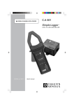
■
K1
K2
AC/DC CURRENT PROBE
■
■
■
■
ON
OL
300
VC
AT
10
m
OF
C
A RH A U
N O VIN
UX
AC/D
CC
UR
II
V/m
A
F
K2
REN
TP
RO
BE
ON
OL
1m
OF V/mA
F
C
A RH A U
N O VIN
UX
AC/D
ENGLISH
User's manual
1
CC
UR
K1
REN
TC
LAM
P
English
CONSULT THE USER’S MANUAL BEFORE USING THE INSTRUMENT.
In the present User’s Manual, the instructions preceded by this symbol, if they are
not respected or followed correctly, may give rise to bodily injury or damage the
instrument and installations.
READ THE INSTRUCTIONS BEFORE USING THE INSTRUMENT !
You have just acquired a K1 or K2 current probe and we thank you for your confidence.
To get the best service from your instrument :
■ read carefully this user manual
■ respect the safety precautions
SAFETY PRECAUTIONS
■ Do not use the K1 and K2 probes on uninsulated conductors at a potential greater than
300 V in relation to the earth.
■ Ensure that the associated measurement instrument has the same electrical protection
specifications as the current probe.
■ For measurements in DC current, ensure zero value at the output. Set if necessary (see
“How to use”).
■ Do not expose the probe to running water.
■ Keep the jaw faces perfectly clean (see Ch.5.2 Cleaning).
TO ORDER
K1 current probe ............................................................................................. P01.1200.67
K2 current probe ............................................................................................. P01.1200.74
Supplied in a carrying case with :
- 1 user manual in 5 languages,
- 9V alkaline battery,
- 1 set of labels to stick on the instrument,
- 1 test certificate.
Spares :
- 9V alkaline battery ........................................................................................ P01.1006.20
- Carrying case ................................................................................................ P01.2980.22
2
SUMMARY
1. Presentation ......................................................................................................................................4
2. Description .........................................................................................................................................4
3. How to use ........................................................................................................................................5
3.1. Switching on ..........................................................................................................................5
3.2. Adjusting DC zero current .................................................................................................... 5
3.3. Measurement ....................................................................................................................... 5
3.4. Overload indication .............................................................................................................. 5
4. Specifications .................................................................................................................................
4.1. Reference conditions ...........................................................................................................
4.2. Operating conditions ............................................................................................................
4.3. Metrological conditions ........................................................................................................
4.4. Mechanical conditions ..........................................................................................................
4.5. Electrical specifications ........................................................................................................
4.6. Electromagnetic compatibility ...............................................................................................
6
6
6
7
9
9
9
5. Maintenance ...................................................................................................................................
5.1. Changing the battery ............................................................................................................
5.2. Cleaning ...............................................................................................................................
5.3. Metrological check ...............................................................................................................
10
10
10
10
6. Warranty ......................................................................................................................................... 10
6.1
Repair .................................................................................................................................. 10
7. Appendices .....................................................................................................................................
7.1
Error as a function of a DC primary current .........................................................................
7.2
Error as a function of AC primary current .............................................................................
7.3
Max error as a function of the frequency ..............................................................................
7.4
Phase shift as a function of the frequency ...........................................................................
7.5
Maximum permitted peak current on permanent overload ...................................................
7.6
Description ...........................................................................................................................
3
11
11
12
13
14
14
15
1. PRESENTATION
The K1 and K2 current probes enable the measurement of low DC or AC currents, without
opening the circuit being worked on. They connect to a multimeter or any other instrument
that has a voltage input and output impedance ³ 1 MW £ 100 pF.
These probes measure on one hand, DC currents from 1 mA to 4.5 A for the K1 probe and
from 0.1 to 450 mA for the K2 probe, and on the other hand, sinusoidal AC currents from
1 mA to 3 A for the K1 probe and from 0.1 to 300 mA for the K2 probe.
These probes output the current measured in the form of a voltage that is the image of the
primary current, in form and amplitude.
They have a single 1 mV/mA range for the K1 and 10 mV/mA range for the K2.
Both are equipped with an On/Off switch, a zero reset thumbwheel and two light indicators,
one for overload, the other for the voltage of the battery power supply.
The probe is in the form of a small clamp with a clamping capacity of 3.9 mm diameter. It
is connected to an adapter case by a multiconductor attached lead, shielded and insulated,
length 1.5 m.
In this case are the electronics of the probe and the 9 V battery power supply (type 6LR61,
6LF22 or NEDA 1604). The battery life is approximately 20 hours with an alkaline battery.
The measurement output is ensured by two male safety plugs Ø 4 mm, standard 19 mm
spacing, attached to the case. This case plugs directly into the associated measurement
instrument and thus leaves the user’s hands free to manipulate the clamp.
2. DESCRIPTION
The K1 and K2 consist of a sensor linked to an adapter unit by an attached cable (see
diagram on the last page of the user manual).
Sensor :
➊
➋
➌
➍
Passage of conductor
Jaws
Hand-held part
Cable attached to the sensor/case
Adapter case :
➎
Adjust zero DC thumbwheel
➏
On/Off switch
➐
Battery “ON” indicator
➑
“OL” overload indicator
➒
4 mm Ø measurement output sockets
4
3. HOW TO USE
Do not use the K1 and K2 current probes on cables or conductors at a potential
in relation to the earth , greater than 300 V.
3.1. SWITCHING ON
Put the sliding switch ➏ to the appropriate position (1 mV/mA for the K1 and 10 mV/mA for
the K2). Correct operation is shown by the green “ON” light ➐ which indicates good battery
condition. If this indicator does not light, or goes out, it is necessary to change the battery
(see Ch. 5.1).
3.2. ADJUST ZERO DC
■ Ensure that the jaws of the clamp are correctly closed and they do not enclose any
conductor.
■ Plug the output connectors ➒ of the adapter case of the probe into your measurement
instrument. Switch on the probe (see Ch. 3.1).
■ Select the most sensitive voltage range of your measurement instrument.
■ Press the DC zero thumbwheel ➎ and at the same time rotate it to obtain zero on the
display.
3.3. MEASUREMENT
After having switched on the probe :
■ Connect the measurement instrument with the appropriate voltage range and adjust
zero DC (refer to Ch.3.1. and 3.2. above).
■ Enclose the conductor to measure between the jaws ➊ of the clamp. The value measured
is displayed directly on the associated instrument as a function of the input/output ratio
of the probe.
■ To obtain the value of the current in the cable, apply to the value measured, the
appropriate conversion ratio, as a function of the voltage range selected on the
measurement instrument and the sensitivity of the clamp.
3.4. OVERLOAD INDICATION
The detection of overload or overrange of the range of the probe, is signalled by the red
coloured “OL” indicator ➑. This indicator lights up for a peak current greater than 4.5 A for
the K1 and 450 mA for the K2.
5
4. SPECIFICATIONS
■
Measurement range
Current
DC
AC
Peak
K1
1 mA…4.5 A
1 mA…3 A
1 mA…4.5 A
K2
0.1… 450 mA
0.1…300 mA
0.1…450 mA
■
Input/output ratio
■
■
■
Rise time from 10 to 90% Vs
Rise time from 90 to 10% Vs
Output noise from DC to 3 kHz
■
Output impedance
■
Zero adjust
■
Rollover*
K1
K2
:
:
:
:
:
:
:
:
:
:
:
:
K1
K2
K1
K2
K1
K2
K1
K2
1 mV/mA
10 mV/mA
< 200 µs
< 200 µs
100 µV
1mV
220 W ±15%
220 W ±15%
±30 mA
±15 mA
±0.3% from 120 mA to 4,5 A
±0.3% from 20 mA to 450 mA
* Difference in measurement of 2 currents of the same value but opposite direction.
4.1. REFERENCE CONDITIONS
■
■
■
■
■
■
■
■
Temperature
:
Humidity rate
:
Battery voltage
:
Magnetic field
:
Impedance of the measurement instrument :
Absence of external AC magnetic field
Absence of electric field
Measurement for a DC current or a sinusoidal
18...28°C
20...75% RH
9 V ± 0.1 V
Earth’s DC field
•³1 MW
£ 100 pF
AC current 45...65 Hz
4.2. OPERATING CONDITIONS
The
and
■
■
■
■
■
■
instrument must be used in the following conditions to satisfy the safety of the user
the metrological performance.
Use indoors
Altitude
: £ 2000 m
Temperature
: -10...+55°C
Relative humidity
: < 85% RH ( £ 35°C) with linear decrease to 75% RH at 55°C
Storage
: -40...+80°C / RH £ 85%
Transportation altitude : £ 12000 m
6
Graph of climatic conditions
Storage
Reference
Use
90
Relative humidity in % of RH
80
70
60
50
40
30
20
10
0
-50
-40
-30
-20
-10
0
10
20
30
40
50
60
70
80
90
Temperature in °C
4.3. METROLOGICAL SPECIFICATIONS
Intrinsic errors
The errors specified below, correspond to measurements made in the reference conditions
(see Ch. 4.1).
■
On DC current
• K1 probe
Primary current
Error
1…10 mA
10…120 mA
± (2% Vs ± 0.2 mV) ± (2% Vs ± 0.1 mV)
120 mA…4.5 A
± 1% Vs
• K2 probe
Primary current
0.1…1 mA
1…12 mA
12…450 mA
Error
± (3% Vs ± 2 mV)
± (2% Vs ± 2 mV)
± 1% Vs
Graph of max. error as a function of a DC primary current : see in appendices,
page 47.
7
■
Intrinsic error on AC current 45...65 Hz
• K1 probe
Primary current
Error
1...10 mA
10...120 mA
120 mA...3 A
± (3% Vs ± 0.3 mV) ± (3% Vs ± 0.1 mV)
Phase shift
-
±1% Vs
-9° maxi
• K2 probe
Primary current
Error
0.1...1 mA
1...12 mA
12...300 mA
± (3% Vs ± 0.5 mV) ± (2% Vs ± 0.5 mV)
Phase shift
-
±1% Vs
-9° maxi
Graph of max. error as a function of an AC primary current (45...65 Hz) : see in
appendices, page 48.
Distortion parameters
■ Influence of frequency on the measurement (add to the error in the field of reference) :
2% VS from 65...440 Hz
< 3 dB de 440 Hz…1.5 kHz. See graph of max error as a function of the frequency, in
appendices, page 49.
■
■
Influence of the frequency on the phase shift : see graph of phase shift as a function
of the frequency for a current of 1 A RMS for K1 probe, and 0.1 A for K2 in appendices,
page 50.
Battery voltage : £ 0.1% Vs/V
■
Temperature
■
Humidity 10...90% RH at ambient temperature : £ 0.2% Vs
:
K1 £ 1% Vs/10°C
K2 £ 0.7% Vs/10°C
8
4.4. MECHANICAL SPECIFICATIONS
■
Drop height
■
Protection from shocks
: 100 g to IEC 68-2-27
■
Vibrations
: 5...15 Hz : 1.5 mm peak
15...25 Hz : 1 mm peak
25...55 Hz : 0.25 mm peak
sweep speed 1 octave/min, duration 10 min
for each axis (3 axes) to IEC 68-2-6
■
Watertightness
: IP 40 to IEC 529
■
Dimensions
: probe (W x H x D): 111 x 15 x 25 mm
case (W x H x D) : 135 x 64 x 28 mm
cable attached probe/case : 1.5 m
■
Weight of set
: 250 g
: 1 m on oak receptacle on concrete to IEC 1010
4.5. ELECTRICAL SPECIFICATIONS
Permanent overload
See graph of maximum permitted peak current on permanent overload, in appendices,
page 50.
The K1 and K2 probes conform to IEC 1010-2-031 / 300 V / Installation category II.
4.6. ELECTROMAGNETIC COMPATIBILITY
■
Immunity
Generic standard
: EN 50082.1
Fundamental standard : IEC 1000-4-3, aptitude criteria A
with maximum degradation of :
K1 probe : - DC current : 15 mV at zero
- AC current (60 Hz) : 2 dB from 10 mA...4.5 A
K2 probe : - DC current : 100 mV at zero
- AC current (60 Hz) : 2 dB from 1 mA…450 mA
■
Emissivity :
Generic standard
: EN 50081.1 negligible level of emissivity of the probe
9
5. MAINTENANCE
For maintenance, use only specified spare parts. The manufacturer will not
be held responsible for any accident occuring following a repair done other
than by its after sales service or approved repairers.
5.1. CHANGING THE BATTERY
When the probe is in the "On" position, if the green “ON” indicator is out, it means that the
battery is dead. To change it proceed as follows :
■
■
■
■
Completely disconnect the probe from the circuit to measure and the measurement
instrument it is connected to.
Undo the screws holding the base of the case in place.
Change the 9 V battery (type 6LF22, 6LR61 or NEDA 1604).
Put the base of the case back in place and retighten the screws.
5.2. ENTRETIEN
The probe must not enclose a cable and must be disconnected from the
measurement instrument. Never run water on the probe.
■
■
■
Keep the jaw faces perfectly clean
Cleaning the body of the probe, the case and the lead with a damp cloth moistened
with soapy water.
Rinsing is also done with a damp cloth moistened with clear water.
5.3. METROLOGICAL CHECK
It is essential that all measuring instruments are regularly calibrated.
For checking and calibration of your instrument, please contact our accredited laboratories
(list on request) or the Chauvin Arnoux subsidiary or Agent in your country.
6. WARRANTY
Our guarantee is applicable for twelve months after the date on which the equipment
is made available (extract from our General Conditions of Sale, available on request).
■ Repair under warranty or out of warranty
For any operation under warranty or out of warranty, please return the product to your
distributor.
10
7. APPENDICES
7.1 ERROR AS A FUNCTION OF A DC PRIMARY CURRENT
7.1.1 K1 probe
25%
Max
20%
Min
15%
10%
5%
0%
-5%
-10%
-15%
-20%
-25%
1
10
100
1.000
10.000
mA DC
7.1.2 K2 probe
20%
Max
15%
Typ.
Min
10%
5%
0%
-5%
-10%
-15%
-20%
0.10
1.00
10.00
mA DC
11
100.00
1000.00
7.2 ERROR AS A FUNCTION OF AC PRIMARY CURRENT (45...65 Hz)
7.2.1 K1 probe
40 %
Max
Min
30 %
20 %
10 %
0%
-10 %
-20 %
-30 %
-40 %
1
10
100
1.000
10.000
mA AC
7.2.2 K2 probe
20%
Max
15%
Typ.
10%
Min
5%
0%
-5%
-10%
-15%
-20%
0.10
1.00
10.00
mA DC
12
100.00
1000.00
7.3 MAX ERROR AS A FUNCTION OF THE FREQUENCY
7.3.1 K1 probe
0%
-5 %
-10 %
-15 %
-20 %
-25 %
-30 %
10
100
1000
10000
Frequency in Hz
7.3.2 K2 probe
5%
0%
-5%
-10%
-15%
-20%
-25%
-30%
10
100
1000
Frequency in Hz
13
10000
7.4
PHASE SHIFT AS A FUNCTION OF THE FREQUENCY
0°
K1 : 1 A RMS
K2 : 0.1 A RMS
-50°
-100°
-150°
-200°
-250°
10
100
1000
10000
Frequency in Hz
7.5
MAXIMUM PERMITTED PEAK CURRENT ON PERMANENT OVERLOAD
250 A AC
200 A AC
150 A AC
100 A AC
50 A AC
0 A AC
1
10
100
Frequency in Hz
14
1000
10000
7.6
Description (see page 14)
64
19
27,7
18,3
➒
➊
➋
➑
➐
OL
111
139,4
ON
10 mV/mA
➏
OFF
➌
K2
AC/DC CURRENT PROBE
➎
15
27,8
➍
Sizes in mm
15
03 - 97
Code 906 129 385 - Ed. 1
Austria : CA Ges.m.b.H - Slamastraße 29/1/3 - 1230 Wien - Tel. : (1) 61 61 9 61 - Fax : (1) 61 61 9 61 61
Deutschland : CA GmbH - Honsellstraße 8 - 77694 Kehl / Rhein - Tel. (07851) 50 52 - Fax (07851) 7 52 90
España : CA Iberica - C/Roger de Flor n° 293, 4° 1a - 08025 Barcelona - Tel. (93) 459 08 11 - Fax (93) 459 14 43
Italia : AMRA CA SpA - Via Torricelli, 22 - 20035 Lissone (Mi) - Tel. (039) 2 45 75 45 - Fax (039) 48 15 61
Schweiz : CA AG - Einsiedlerstrabe 535 - 8810 Horgen - Tel. (01) 727 75 55 - Fax (01) 727 75 56
U.K : CA UK Ltd - Waldeck House - Waldeck Road - Maidenhead - Berkshire SL6 8BR - Tel. (01628) 788 888 - Fax (01628) 28 099
USA : CA Inc - 99 Chauncy Street - Boston MA 02111 - Tel : (617) 451 0227 - Fax : (617) 423 2952
USA : CA Inc - 15 Faraday Drive - Dover NH 03820 - Tel. (603) 749 6434 - Fax (603) 742 2346
CA Mätsystem AB - Box 4501 - Sjöflygvägen 35 - 183 04 Täby
Tfn: 08-505 268 00 - Fax: 08-505 268 1052
- Epost: [email protected]