1
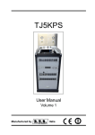
“Automation Gone Cellular”
Model CS-100
User Manual
A product of:
P.O. Box 33157
Cleveland, Ohio 44212
www.cell-switch.com
Cell Switch™ Model CS-100
Cell Switch™
Model CS-100
Remote Controller
User Manual
IMPORTANT!
Please read through the instruction manual before you start to install and program
the device.
If you are unsure how to connect the device you wish to control please refer to a
qualified person.
Description:
The CELL SWITCH™ MODEL CS-100 is to be a versatile option as a Single Output Relay system with
normally open and closed contacts to provide a low cost solution for a wide range of applications only
requiring a simple on/off command. It is activated by calling its cell phone number and it will reject
the call without answering and switch on the device connected to it. There is no call costs incurred
when dialing the unit and it will only recognize an authorized telephone number calling it and reject
unauthorized callers the call without answering. The system has the capability to load up to 25
numbers in the white list as authorized users and the single output relay can be programmed to
switch on for a pre-determined length of time whenever the CELL SWITCH™ MODEL CS-100 is called,
alternatively the output relay can be permanently switched on or off by sending the CELL SWITCH™
MODEL CS-100 a text message.
Cell Switch™ – USER MANUAL – Rev. 1.4
Cell Switch™ Model CS-100
Main Switch
(Fused)
Antenna
Battery for Time
Clock
+12VDC OUT
Connector
12VDC Internal
Power Supply
Battery Back-up
Connector
Charging Status
Insert SIM Here
AC 80-260V IN
Connector
PC Programming
Connector
10 Amp
Protection Fuse
for Output Relay
Signal Indicator
Power Indicator
Input AC Power
120V
Output Relay
Terminal Rated at
10 amps @ 120V
Requirements:
A mobile phone SIM card with sufficient credit to send confirmation text messages when programming
the CELL SWITCH™ MODEL CS-100 unit. It is our recommendation to utilize a T-Mobile SIM card with
unlimited nationwide messaging.
If the unit did not arrive preloaded with a SIM Card it is important
to follow the following step:
SIM Card Configuration: You must remove the PIN request from the SIM before inserting it in the
unit; otherwise the device will not work. This can be done either by the provider or simply insert the
SIM in a T-Mobile phone and disable the PIN Request and the Voicemail function. It is important to
make sure that the voicemail does not pick up the call.
Cell Switch™ – USER MANUAL – Rev. 1.4
Cell Switch™ Model CS-100
Installation:
To install the CELL SWITCH™ MODEL CS-100 you will need to mount the unit within the close
proximity of a 120V power supply and the device you wish to control. The CELL SWITCH™ MODEL
CS-100 comes with its own 12 Volt Amp Internal Power Supply all mounted in an IP65 Enclosure and
rated for indoor our exterior applications. The unit is supplied with a 10 amp rated plug to enable the
easy connection to appliances.
Once you have installed the CELL SWITCH™ MODEL CS-100 and make the required connections to
the device to be controlled the SIM Card can now be Installed in the Holder as described in the
schematic drawing and the Power Supply connected and Switched on.
The Signal Led (Green) on the board will oscillate infrequently until it finds and logs on to the Network
and will then flash every 3 seconds constantly and if does not happen then the unit has not logged on
and it may be required to use an extension antennae or alternative network provider.
Once the system has logged on the Network the first thing you need to establish is the actual Signal
Strength of the Location of the Installation to secure a constant signal strength for the reliability of the
CELL SWITCH™ MODEL CS-100 and this can be done by simply sending the following SMS Text
message to the unit.
*PSSW*SGH?
The system will now send back a report to indicate the Signal Strength at the location of the CELL
SWITCH™ MODEL CS-100 and you will receive a similar message as follows.
The Signal Strength range can typically vary from “3-31” of which it is suggested that a consistent
Signal Strength acceptable should be at least 12 and above as the signal network strengths can vary
dramatically.
Connection Details:
The unit is shipped prewired as a normally open contact, this means
that when the relay is activated the device that is connected the unit
will be turned on. If for some reason you would like the device to be
on all the time then the unit should be wired as normally closed.
The wire on J5 Pin 6 should be moved to J5 Pin 4.
Warning: The unit should be unplugged before opening the cover
and making any changes. If you are unsure how to connect the
device you wish to control please refer to a qualified person.
Cell Switch™ – USER MANUAL – Rev. 1.4
Cell Switch™ Model CS-100
J7
J5
1
2
3
4
5
6
G
L
N
NC
C
NO
Earth
Line
Neutral
AC 120V Power
Input
Port
Output Relay Rated
10 amps @120 volts
Descriptions
1
Earth (GND)
2
Line (L)
3
Neutral (N)
4
NORMALLY CLOSED (N.C)
5
COMMON (COM)
6
NORMALLY OPENED (N.O)
Supply AC Power 120V to the unit
OUTPUT RELAY 10 amps @120 volts Max.
Example Connections
Heater
120VAC
A heater connected to output relay.
When the CELL SWITCH™ MODEL CS100 is activated the relay contact will
switch from the NC position to the NO
position thus making the circuit and the
heater will be switched on
Factory Default Settings
The default settings are, open access mode*, the default password is 12345
* Any call to the CELL SWITCH™ MODEL CS-100 will activate the unit
Cell Switch™ – USER MANUAL – Rev. 1.4
Cell Switch™ Model CS-100
Programming the CELL SWITCH™ MODEL CS-100
The CELL SWITCH™ MODEL CS-100 is programmed by sending it SMS text commands from a mobile
phone, these are sent to the telephone number of the SIM card installed in the CELL SWITCH™ MODEL
CS-100 .
The password command must pre-fix all SMS text commands it is recommended the default password
be changed.
Remember that all SMS text commands must always be sent in CAPITAL LETTERS
DO NOT add spaces or any other characters otherwise the system will simply ignore the commands
Programming Commands
The CELL SWITCH™ MODEL CS-100 is pre- programmed and controlled by sending certain SMS
Text Messaging to the unit and is password protected with a factory default setting of five digits preset
at *PSSW12345 and this prefixes any commands to the unit.
Changing the Password
It is possible to Change this password to another 5 digit number by sending the following SMS Text
message to the unit and we assume the new Password is
54321
*PSSW12345*NPW=54321
You will receive the following message back from the unit to confirm the password has been changed
NPW=54321
The new password is now *PSSW54321
Checking Signal Strength
*PSSW*SGH?
The system will now send back a report to indicate the Signal Strength at the location of the CELL
SWITCH™ MODEL CS-100 and you will receive a similar message as follows.
SIGNAL STRENGH < 14 > which indicates a mid range of Signal Strength and is acceptable to
maintain a constant network as the networks will vary and can drop as low as < 5 > and any lower
the unit can well log off the network and Latch off the Relay if active and give the indication that the
unit is faulty when it is only subject to no Signal Strength.
In this instant the unit will consistently search and communicate with the network until it have reestablished a network link and log back on!
If this happens on a regular basis it is suggested you install an additional External Antenna.
Cell Switch™ – USER MANUAL – Rev. 1.4
Cell Switch™ Model CS-100
Output Relay Latch Time when called
The CELL SWITCH™ MODEL CS-100 can be programmed to latch the Relay from a period of from 1
second up to 12 hours when called and this allows a vast range of flexibility for many applications
from Automatic gates to switching on heating and lighting and remote re-setting of servers etc.
This function can be operated in two modes of security which can be set as desired and the factory
default is “Open Mode” meaning any person who has access to the actual SIM Card telephone
number of the unit can operate the system and this is usually only used for setting up the system or
for low security applications based on applications of convenience.
The other mode of operation is the “Security Mode” which only allows the persons who have their
telephone numbers entered into the security list of the unit to access the system and this is usually
also done once all the pre-programming of the telephone numbers has been programmed into the
system and the Latch times set. (For additional information see Setting Security Mode below)
The CELL SWITCH™ MODEL CS-100 comes preset to latch the relay for a period on 1 second and to
change this latching period time to say 1 hour you would use the following programming command
which is always calculated in seconds with 5 digits and therefore the command would be sent as
03600.
To pre-program to unit to latch the relay for 1 hour when called you would send the following SMS
Text message to the unit, using the new password *PSSW54321
*PSSW54321*RLY=03600 and the unit will return the following SMS Text Message.
RELAY SET - 03600 and the Relay of the unit will now latch for one hour whenever the unit is called
(Subject to authorization of the number if Security Mode Set)
In addition to the pre-programmed latching time when the unit is called, it is also possible to
temporary or permanently latches the Relay via SMS Text message without affecting the existing
programming function when the unit is called.
If it is required to latch the relay temporarily for say 2 hours you would use the following SMS text
command and again based on seconds.
*PSSW54321*RLYT=07200 and the unit will return the following SMS Text Message.
RELAY TEMP 07200 and the relay has been temporarily latched for 2 hours as set in seconds.
If you require to latch the Relay permanently “ON” and back “OFF” again this can be done by using
the following SMS Text commands.
Cell Switch™ – USER MANUAL – Rev. 1.4
Cell Switch™ Model CS-100
To latch the relay permanently “ON” you would send the following SMS text command to the unit.
*PSSW54321*RLYP=ON and the unit will return the following SMS Text Message.
RELAY <P> ON
To latch the relay permanently back “OFF” you would send the following SMS text command to the
unit.
*PSSW54321*RLYP=OFF and the unit will return the following SMS Text Message.
RELAY <P> OFF
If you need to check the status the Relay and what mode it is you can send a SMS Text request using
the following command.
*PSSW54321*RLY? And the unit will return the following SMS Text Message. (Example assuming
Relay is still part active after programming to be on for 2 hours and 1 hour remaining.
RELAY ON 03600
If the relay has been programmed as permanently on the unit will return the following S.M.S Text
message.
RELAY ON <P>
If the Relay is inactive the unit will return the following SMS Text message.
RELAY OFF
SMS Report after latching the unit by calling the unit
It is possible to receive a text message whenever the Relay is latched via Phone Call which will report
both Relay On and Relay Off to the user that has call the unit and only practical for certain
infrequent applications and the factory default for this function is off.
To enable this function you would send the following SMS text message to the unit.
*PSSW54321*RLYM=ON and the unit will return the following SMS Text message
RLYM-ON and the unit will return both Relay On and Relay Off status SMS Text messages when
called.
To turn this function off you would send the following SMS Text Message to the unit.
Cell Switch™ – USER MANUAL – Rev. 1.4
Cell Switch™ Model CS-100
*PSSW54321*RLYM=OFF and the unit will return the following SMS Text Message
RLYM=OFF and this function is now disabled.
Programming in the administrator number in the system
It is possible to program 1 administrator number into the system that will be recognized as
authorized number that have programming access to the system as well as activate the device it is
connected to.
To add 09876543210 as the administrator you would send the following SMS text message to the unit
*PSSW54321*ADM1=09876543210
Programming in the authorized telephone numbers in the system
It is possible to program up to 250 Land line or Mobile Phone Numbers into the system that will be
recognized as authorized numbers that can access the system and activate the Device it is connected
to. All telephone numbers can be programmed into the system using only the 7 digits of the
telephone number as the system will scan the numbers of the last digits and accept and authorize that
number to allow access to the system and will then reject the incoming call and activate the Relay as
set and operate the device it is connected to. Any Unauthorized numbers calling the unit will result in
the system rejecting the call and refusing access to the system .
It is Possible to program up to 5 telephone numbers into the system using the same SMS Text
command and you would use the following command to enter the first 5 examples of numbers, based
on using the last 7 digits of the number.
*PSSW54321*CLD01=1212121,CLD02=1313131,CLD03=1414141,CLD04=1515151,CLD05
=1616161 and the unit will return the following SMS Text Message.
CLD01=1212121
CLD02=1313131
CLD03=1414141
CLD04=1515151
CLD05=1616161
END
Please note that you can 5 telephone numbers into the system using the same SMS text command
only for up to the first 25 authorized users.
If you wish to just replace a number you can just replace say number 6 in the list by sending the
following SMS Text command
Cell Switch™ – USER MANUAL – Rev. 1.4
Cell Switch™ Model CS-100
*PSSW54321*CLD06=156561 and the unit will return the following SMS Text Message.
CLD06=1561561 and the previous number “1717171” has been replaced with “1561561”
If the list number is more than 25, you can only program individual telephone number in 1 text
message like the below example
*PSSW54321*CLD26=1735399
If the list number goes above 100, you would send the text command like the following example
*PSSW54321*CLD100=1324590
If you require checking or confirming what numbers are in the “Authorized List” you can either
request all of the numbers in the list or request any particular one number in the list.
To request a single number stored you would send the following SMS Text Message to the unit.
*PSSW54321*CLD05? And the unit will return the following similar SMS Text Message.
CLD05=1616161
Setting the Security Mode
Once all the telephone numbers have been programmed into the system you can now set the
“Security Mode” and to program this you would send the following SMS Text message to unit.
*PSSW54321*SSM=ON and the unit will return the following SMS Text Message.
SSM=ON and the “Security Mode” is on
To set the system back to “Open Mode” you would send the following SMS text message to the unit
*PSSW54321*SSM=OFF and the unit will return the following SMS Text Message.
SSM=OFF and the “Open Mode” has been set to factory default.
Cell Switch™ – USER MANUAL – Rev. 1.4
Cell Switch™ Model CS-100
Setting the Operating Time for Output relay
The system has the function to activate the output relay up to twice a day at a programmable time.
To program the operating time for output relay you would send the following text command to the
unit.
*PSSW54321*SMW=SS,MM,HH,TTT,G;
SS is a 2 digits value stand for seconds
MM is a 2 digits value stands for minutes
HH is a 2 digits value stand for hours
TTT is a 3 digits value stand for Turn ON time in seconds
G stands for Group (Time Section) number 1 - 2
For example assume that you want the output relay to turn on for 20 seconds at 8.30am, you would
send the following SMS message to the unit.
*PSSW54321*SMW=00,30,08,020,1;
The unit will return the following SMS Text Message.
SMW=00,30,08,020,1;
For example assume that you want the output relay to turn on for 100 seconds at 6.00pm for the
second time section, you would send the following SMS message to the unit.
*PSSW54321*SMW=00,00,18,100,2;
The unit will return the following SMS Text Message.
SMW=00,00,18,100,2;
Setting the Time Clock
To set the time, you can send the following SMS command to the unit. The time must enter in 24 Hour
format.
*PSSW54321*TSET=SS,MM,HH;
SS is a 2 digits value stand for seconds
MM is a 2 digits value stands for minutes
HH is a 2 digits value stand for hours
For example to set the time 8.00am, you would send *PSSW54321*TSET=00,00,08; to the
unit and the unit will return the following SMS text message TSET=00,00,08;
Cell Switch™ – USER MANUAL – Rev. 1.4
Cell Switch™ Model CS-100
To check the time clock you may send text command *PSSW54321*TREAD? to the unit and the unit
will return the following SMS text message The time is SSMMHH: 00,00,08;
Power Down Alarm
The system has the function to send a text alert in the event the main power is lost and the system is
relying on battery backup.
When power failure you would receive the following text message from the unit
POWER DOWN
When power restored you would receive the following text message from the unit
POWER RESTORED
Battery low Alarm
The system has the function to send a text alert in the event the battery is running low.
You would receive the following text message from the unit when battery low
Battery low voltage
Reset the CELL SWITCH™ MODEL CS-100
To reset the system to factory default you would send the following SMS Text message to the unit.
*PSSW54321*RESET* and the unit will return the following SMS Text Message.
<UNIT RESET>
Warning!
This command will reset the password to *PSSW12345 and the reset the output
latch time to 1 second and completely wipe the numbers stored with the memory
of the system!
Cell Switch™ – USER MANUAL – Rev. 1.4
Specifications
Model
CELL SWITCH™ MODEL CS-100
Operating Voltage
12 or 24V DC
Operating Current
Maximum 500mA, typically 55mA
Relay Connections
Normally Open, Normally Closed & Common Contacts
Relay Contacts
NC: 10A@120VAC/28VDC NO: 20A@120VAC/28VDC
GSM Frequency MHz
GSM850, GSM900, GSM1800, GSM1900
Humidity
Less than 80% RH
Operating Temperature
-20°C to 55°C
Physical size
157 x 90 x 60 mm
Protection
IP65
Weight
800 Grams
Approvals
C.E.