1
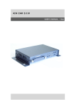
Drawing No. :- TPC252
Issue
:- 1
Date
:- 13/10/03
EBAC MODEL
CD425 (1018110)
INDUSTRIAL DEHUMIDIFIER
OWNER’S MANUAL
Ebac Industrial Products
704 Middle Ground Boulevard
Sales: 800-934-9194
Newport
News, VA 23606
Tel: 757 873 6800 Fax: 757 873 3632
Website: www.ebacusa.com
CD425 OWNERS MANUAL
Drawing No. :- TPC252
Issue
:- 1
Date
:- 13/10/03
UNPACKING
Carefully remove the CD425 dehumidifier unit from its packing and visually check for signs of
transit damage. If there is evidence of damage DO NOT attempt to operate the unit, call your
supplier for advice. Do not discard the packing, as it will be useful when transporting the
dehumidifier unit in the future.
INTRODUCTION
The Ebac CD425 dehumidifier removes moisture from the air that circulates through it. The
resulting reduction in relative humidity protects buildings and their contents from the adverse
effects of excess humidity.
The CD425 Dehumidifier comprises of:
a)
b)
c)
d)
e)
f)
A compressor
Refrigerant evaporator coils
Refrigerant condenser coils
Circulation fan
A drain tray for collecting and disposing of condensed moisture
A cabinet to house the above components.
The fan draws the moist air through the evaporator coils which cools the air below its dew point.
Moisture forms on the evaporator and is collected in the condensate tray which leads away to a
permanent drain. The cooled air then passes through the hot condenser, where it is reheated
using the same energy removed during the cooling phase and the additional heat generated by
the compressor. The air is, therefore, discharged from the dehumidifier at a slightly higher
temperature, but a lower relative humidity, than that at which it entered. Continuous circulation
of air through the dehumidifier gradually reduces the relative humidity within the area being
dehumidified.
Where large amounts of moisture are required to be removed from the area, more than one
dehumidifier may be required, please contact your local distributor for advice.
CD425 OWNERS MANUAL
Drawing No. :- TPC252
Issue
:- 1
Date
:- 13/10/03
SPECIFICATIONS
MODEL:
CD425
HEIGHT:
1190 mm
WIDTH:
1100 mm
DEPTH:
460 mm
WEIGHT:
160 kg
AIRFLOW:
1750 CFM
(3000M/Hr)
TOTAL POWER:
6.0Kw (MAX)
MAXIMUM OPERATING
TEMPERATURE:
35ºC (95ºF)
POWER SUPPLY:
220V 3PH 60hz
REFRIGERANT:
R22
CHARGE:
2.5Kg
CD425 OWNERS MANUAL
Drawing No. :- TPC252
Issue
:- 1
Date
:- 13/10/03
OPERATION
The CD425 is a self contained low temperature dehumidifier. All electrical contactors,
overloads, etc are housed in an electrical box built inside the unit. The unit is equipped with a
defrost valve which energized every 42 minutes to clear any ice formation on the evaporator
coils. This allows the unit to operate at much lower temperatures, the control panel gives
indication of the set humidity, drying and defrost status.
TEST FOR CORRECT OPERATION
The following procedure should be followed to test the unit for correct operation.
1. After unpacking connect the unit to a 220V 3PH 60hz – 3 wire power supply.
2. Switch fan ON and check for correct fan rotation. (Air blows out of the top of the
machine).
3. Check dehumidification process:
a) Remove the front cover
b) Check the actual relative humidity inside the area
c) Set humidity control to a LOWER value than the actual relative humidity
d) After approximately 6 minutes check the compressor is running
e) Leave the machine to run for 15 minutes. (NOTE: ensure that the set humidity,
see c above, is set very low as the compressor will switch off when the actual RH
coincides with the set point)
f) Observe the evaporator coils
i. If the air temperature is below 20ºC an even coating of ice should cover
the entire evaporator coil
ii. If the temperature is above 20ºC droplets of condensed water should cover
the entire evaporator coil
4. Leave the unit to run for a further 27 minutes after which the unit should go through a 4
minute defrost cycle.
During the defrost cycle the defrost solenoid valve is energized and a warming of the
evaporator coil can be felt.
If after carrying out the above checks the unit does not appear to function correctly refer
to the repairs section or your supplier.
CD425 OWNERS MANUAL
Drawing No. :- TPC252
Issue
:- 1
Date
:- 13/10/03
SYSTEM INSALLATION
POSITIONING
Position the CD425 in the area leaving enough room either end of the unit to allow for easy
servicing. Using a spirit level ensure the level in both direction. Failure to do so may result in the
drain tray overflowing and flooding of the chamber.
WIRING
Connect a suitably fused 3 phase mains power supply to the MAINS T/B terminal block inside
the electrical box located at the control panel end of the machine.
DRAINAGE
Connect the outlet from the drain tray (located behind the front grille and under the evaporator
coils) to a permanent drain.
Please ensure that the drainage does not rise above the level of the CD425’s drain tray. Failure to
observe this requirement will result in internal flooding of the dehumidifier.
CD425 OWNERS MANUAL
Drawing No. :- TPC252
Issue
:- 1
Date
:- 13/10/03
ROUTINE MAINTENANCE
WARNING: ENSURE THAT THE POWER CORD TO THE MACHINE
HAS BEEN DISCONNECTED BEFORE CARRYING OUT
ROUTINE MAINTENANCE ON ITEMS 1, 2, 4, 5, AND 6.
To ensure continued full efficiency of the dehumidifier, maintenance procedures should be
performed as follows:
1.
Clean the surface of the evaporator and condenser coils by blowing the dirt out from
behind the fins with compressed air. Hold the nozzle of the air hose away from the
coil (approx 6”) to avoid damaging the fins. Alternatively, vacuum clean the coils.
WARNING: DO NOT STEAM CLEAN REFRIGERATION COILS.
2.
Check that the fan is firmly secured to the motor shaft and that the fan rotates freely.
The fan motor is sealed for life and therefore does not need oiling.
3.
To check the refrigerant charge, run the unit for 15 minutes and briefly remove the
cover. The evaporator coil should be evenly frost coated across its surface. At
temperatures above 25°C, the coil may be covered with droplets of water rather than
frost. Partial frosting accompanied by frosting of the thin capillary tubes, indicates
loss of refrigerant gas or low charge.
4.
Check all wiring connections.
5.
To check the operation of the defrost system, switch the machine on and leave it
running for approximately 45 minutes. The machine will then enter “Hot Gas”
defrost mode for approximately 4 minutes before returning to normal operation. If
the unit will not defrost, the printed circuit timer board may be defective or the bypass valve may be inoperable.
IF ANY OF THE PRECEDING PROBLEMS OCCUR, CONTACT THE EBAC SERVICE CENTER PRIOR TO
CONTINUED OPERATION OF THE UNIT TO PREVENT PERMANENT DAMAGE.
CD425 OWNERS MANUAL
Drawing No. :- TPC252
Issue
:- 1
Date
:- 13/10/03
REPAIRS
1.
Should an electrical component fail, consult the Factory Service Center to obtain the
proper replacement part.
2.
If refrigerant gas is lost from the machine, it will be necessary to use a refrigeration
technician to correct the fault. Contact the Factory Service Center prior to initiating
this action.
Any competent refrigeration technician will be able to service the equipment. The
following procedure must be used:
a. The source of the leak must be determined and corrected.
b. The machine should be thoroughly evacuated before recharging.
c. The unit must be recharged with refrigerant measured accurately by weight.
d. For evacuation and recharging of the machine, use the crimped and brazed
charging stub attached to the side of the refrigerant compressor.
The charging stub should be crimped and rebrazed after servicing. NEVER allow
permanent service valves to be fitted to any part of the circuit. Service valves
may leak causing further loss of refrigerant gas.
3.
The refrigerant compressor fitted to the dehumidifier is a durable unit that should
give many years of service. Compressor failure can result from the machine losing its
refrigerant gas. The compressor can be replaced by a competent refrigeration
technician.
Failure of the compressor can be confirmed by the following procedure:
a. Establish that power is present at the compressor terminals using a voltmeter.
b. With the power disconnected, check the continuity of the internal winding by
using meter across the compressor terminals. An open circuit indicates that the
compressor should be replaced.
c. Check that the compressor is not grounded by establishing that a circuit does not
exist between the compressor terminals and the shell of the compressor.
CD425 OWNERS MANUAL
Drawing No. :- TPC252
Issue
:- 1
Date
:- 13/10/03
TROUBLESHOOTING
REMEDY
SYMPTOM
CAUSE
Unit inoperative
1. No power to unit
1. Check the power from the power
supply panel
1. Tighten fan
2. Replace the fan motor
3. See Routine Maintenance Section
4. Check the wiring diagram to find
fault and repair
5. Replace the fuse or reset the
circuit breaker
1. Check all of the above
2. Contact the Factory Service Center
3. Contact the Factory Service Center
4. Contact the Factory Service Center
1.
2.
3.
4.
5.
Loose fan on shaft
Fan motor burnt out
Dirty refrigeration coils
Loose electrical wiring
Fuse blown or circuit breaker
tripped
Little or no water extraction
1.
2.
3.
4.
Insufficient air movement
Compressor fault
Loss of refrigerant gas
Blocked filter dryer
Unit vibrates excessively
1. Loose compressor
2. Damaged fan
1. Tighten the nuts on the compressor
mounts
2. Replace fan
Water flooding inside the
machine
1. Drain pipe blocked/frozen
2. Drain pipe too high
1. Clear the obstruction, straighten or
replace
2. No section of the drainage pipe
Little or no airflow
Ebac Industrial Products
704 Middle Ground Boulevard
Newport News, VA 23606
Tel: 757 873 6800 Fax: 757 873 3632
Website: www.ebacusa.com
CD425 OWNERS MANUAL
Drawing No. :- TPC252
Issue
:- 1
Date
:- 13/10/03
CD425
SPARE PARTS LIST
DESCRIPTION
PART NUMBER
QUANTITY
Compressor
3022176
1
Condenser Coil
3020725
1
Evaporator Coil
3020733
3
Defrost valve
3020803
1
Reversible Filter Dryer
3020930
1
Capillary Tube
3014251
12 X 1400mm X 0.047
R22 Freon Refrigerant
3100451
2.5kg
Drain Tube
2014315
3 meters
3/8” Copper Tube
3014203
2 meters
1/2” Copper Tube
3014204
2 meters
5/8” Copper Tube
3014205
2 meters
Cork Tape
3100223
1/2 Roll
Fan Motor
3030140
1
Axial Fan
3010119
1
Solenoid Coil
3030402
1
Humidistat
1132200
1
Momentary Switch
3030634
1
Indicator Lamp Holder
3034513
2
12V 100ma Lamp
3034522
4
Humidistat Control Knob
2017707
1
Contactor 037H0021
3030355
1
Contactor 037H0041
3030362
1
Relay
3030270
1
Overload
3032646
1
Transformer
3031129
1
Delay Timer
1602400
1
Defrost Timer
1601200
1
CD425 OWNERS MANUAL