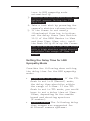
1
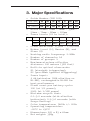
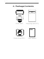
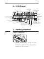
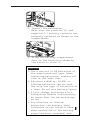
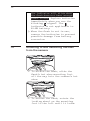
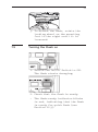
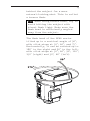
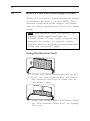
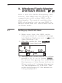
User Manual
Wireless
Flash
RF60
2
Table of Contents
1. Getting to Know your RF60
03
2. Caution and Warnings
04
3. Major Specifications 05
4. Package Contents
06
5. Nomenclature 07
6. LCD Panel
08
7. Getting Started 08
8. On-camera Operation: 18 Local Mode
9. Wireless Flash: 20 Master and Slave Modes
10.Group Aliases 25
11.Advanced Operation 27
12.Personalizing the RF60
39
13.Working with Cactus
Triggers
43
14.External Power 45
15.Forming the Capacitor 46
16.USB Connection 47
17.Optional Accessories 47
18.
Troubleshooting
48
19.Notices 51
20.Warranty 54
3
1. Getting to Know your
RF60
Thank you for purchasing the Cactus
Wireless Flash RF60. We know that you
will enjoy the benefits of your new
wireless portable flash. The RF60 is
unique among other flashes available
on the market. With a built-in
transmitter and receiver, it not
only receives wireless signals, but
it also functions as a commander to
control other RF60s. The
possibilities are endless!
Please take the time to explore all
the features in your new RF60:
–– Built-in wireless commander and
receiver
–– Remote control of power and zoom
levels
–– Group control of up to four groups
with configurable Group Alias
–– Optical Slave with delay feature
–– High power up to Guide Number of
56 meters
–– Compatible with Cactus V6 Wireless
Flash Transceiver
–– Multi-flash feature
–– HSS Sympathy mode provides HSS
support when working with TTL
flashes
4
2. Caution and Warnings
Before using the product, read the
following instructions to ensure
correct and safe use and to help
prevent damage of the Cactus RF60.
1. Turn OFF all your equipment
(Cactus units, cameras, etc.)
before changing batteries or
making a connection.
2. Remove batteries and switch off
the flash when it is not in use.
3. Use only the batteries specified
in this instruction manual.
4. Do not permanently store the
product in a high temperature
environment (i.e., under strong
direct sunlight, near cooking
stoves or oven).
5. The flash should not be submerged
in liquid or exposed to heavy
rain unless it is properly
protected.
6. Do not operate the device in the
presence of flammable gases or
fumes.
7. Do not fire the flash directly
into the eyes of someone at close
range.
8. Do not fire the flash directly at
the driver of a moving car.
5
3. Major Specifications
–– Guide Number (ISO 100):
Zoom (mm) 24
GN (meter) 33
28
35
50
70
80
34
38
45
51
54
56
108
112
124
147
168
177
183
GN (feet)
105
–– Motor zooms: 24mm – 28mm – 35mm –
50mm – 70mm – 80mm – 105mm
–– Power levels (22 in total):
1/1
1/2
1/4
1/8
1/2+0.3
1/4+0.3
1/8+0.3
1/16+0.3 1/32+0.3 1/64+0.3 1/128+0.3
1/16
1/32
1/64
1/128
1/2+0.7
1/4+0.7
1/8+0.7
1/16+0.7 1/32+0.7 1/64+0.7 1/128+0.7
–– Flash durations: 1/300s – 1/20,000s
–– Modes: Local (L), Master (M), and
Slave (S)
–– Working radio frequency: 2.4GHz
–– Number of channels: 16
–– Number of groups: 4
–– Maximum wireless effective
distance: 100 meters (328 feet)
–– Built-in optical slave mode:
S1 (straight triggering);
S2 (pre-flash ignored triggering)
–– Power input:
4 AA batteries (LR6 alkaline or
Ni-MH), rechargeable Ni-MH for
best performance
–– Flash count per battery cycle:
100 (at 1/1 power);
2000 (at 1/128 power)
–– Minimum recycle time:
0.1-5.0 seconds (with alkaline
batteries); 0.1-3.0 seconds (with
Sanyo Eneloop)
–– Color temperature: 5600k +/- 200k
–– Operating temperature:
-20°C to +50°C
–– Dimensions: 205 x 83 x 61mm
–– Net weight: 390g
6
4. Package Contents
Flash RF60
Carrying Case FC-3
Flash Stand FS-2
User Manual
7
5.Nomenclature
WIDE ANGLE DIFFUSER
AND BOUNCE CARD FRESNEL LENS
TRIPOD MOUNT
3.5mm CONNECTOR
OPTICAL SENSOR
EXTERNAL POWER
CONNECTOR
USB PORT
CONNECTOR COVER
CONNECTOR COVER
HOT SHOE
LOCKING WHEEL
HOT SHOE CONTACT
MOUNTING FOOT
BOUNCE ANGLE
INDICATOR
BATTERY COMPARTMENT
DOOR
LCD PANEL
GROUP BUTTON
MODE BUTTON
MULTI/HSS BUTTON
TEST BUTTON/
FLASH-READY INDICATOR
ON/OFF SWITCH
MENU BUTTON
- BUTTON
NEXT BUTTON
+ BUTTON
8
6. LCD Panel
GROUP PANEL
TEXT AREA
ZOOM
LEVEL
POWER LEVEL
INCREMENT
POWER LEVEL
HSS SYMPATHY
MODE
OPERATING
MODES
SELECTION
INDICATORS
STATUS
BAR
CHANNEL
BEEP INDICATOR
OPTICAL SLAVE
HIGH TEMPERATURE
WARNING
BATTERY LEVEL
DELAY INDICATOR
7. Getting Started
7.1
Inserting Batteries
1. Using your thumb, press on the
battery compartment door and
slide it open in the direction
shown by the arrow.
9
2. Install the batteries.
Make sure the positive (+) and
negative (-) battery contacts are
properly oriented as shown in the
compartment.
3. Slide the battery compartment
door in the direction shown by
the arrow to close it.
Caution:
1.
Use a new set of AA batteries of
the same brand and type. When
replacing batteries, replace all
four at the same time.
2.
AA-sized alkaline, Ni-MH, or
lithium batteries can be used.
Use only one type of batteries at
a time. Do not mix battery types.
3.
If you change batteries after
firing many flashes continuously,
be aware that the batteries may
be hot.
4.
For alkaline or lithium
batteries, the battery level
indicator on the LCD will show
when around 50% of the battery
power has been consumed, and
10
the indicator will blink when
the flash does not have enough
power to fire. Replace batteries
immediately when you see the
blinking
signal. The
indicator is not applicable to
Ni-MH battery.
5.When the flash is not in use,
remove the batteries to prevent
possible damage from battery
corrosion.
7.2
Attaching to and detaching the flash
from the camera
1. To attach the flash, slide the
flash’s hot shoe mounting foot
all the way into the camera’s hot
shoe.
2. To secure the flash, rotate the
locking wheel on the mounting
foot to the left until it locks.
11
3. To detach the flash, rotate the
locking wheel on the mounting
foot to the right until it is
loosened.
7.3
Turning the Flash on
1. Switch the On/Off Switch to ON.
The flash starts charging.
2. Check that the flash is ready.
- The flash-ready indicator blinks
in red, indicating that the flash
is ready for quick flash (see
Section 12.3).
12
- Once fully charged, the flashready indicator stays red and the
flash is ready to give full power
output.
- Press the
button to fire a
test flash.
Caution:
1.
When the flash is switched ON but
not used, after a certain period
of time, the flash’s power turns
off automatically. However, the
flash still consumes power and
batteries discharge over a long
period of time, which may damage
the battery contacts of the flash.
Therefore, shut off the flash
power if the flash is not in use.
2.
If you fire more than 20
continuous flashes at full power
in short intervals, the inner
overheating prevention function
may be activated to prolong the
recycling time to about 8 seconds
– 20 seconds. The temperature
warning signal
will appear in
the status bar of the LCD screen.
If this occurs, allow a rest time
of about 15 minutes, and the flash
will then return to normal.
7.4
Adjusting the Flash Head
By pointing the flash toward a wall or
ceiling, the flash will bounce off
the surface before illuminating the
subject. This will soften the shadows
13
behind the subject for a more
natural-looking shot. This is called
a bounce flash.
Tip: When using bounce flash, try to
avoid hitting the subject with
direct flash light. Make sure the
flash head is sufficiently angled
away from the subject.
The flash head of the RF60 can be
tilted up to a vertical angle of 90˚,
with click stops at 30˚, 60˚, and 75˚.
Horizontally, it can be rotated up to
180˚ to the right and 90˚ to the left,
with click stops at 30˚, 60˚, 90˚, 120˚,
150˚ (right) and 30˚, 60˚ (left).
14
7.5
Bounce Card and Wide Angle Diffuser
There is a bounce card and wide angle
diffuser set built in the RF60. The
bounce card and wide angle diffuser
can be used separately or at the same
time.
Tip: The bounce card is useful in
bounce flash applications to
direct some of the light toward the
subject in order to create catch
lights and/or soften strong shadows
from the bounced light.
Using the Bounce Card
1. Point the flash head upward by 90°.
2. Pull out the wide angle diffuser.
The bounce card will come out at
the same time.
3. Push the wide angle diffuser back
in. The bounce card will be ready
for use.
15
Using the Wide Angle Diffuser
1. Pull out the wide angle diffuser
and place it over the flash head as
shown. The bounce card will come
out at the same time.
2. Push the bounce card back in.
The flash will illuminate at 18mm
coverage.
7.6
Choosing the Operating Mode
There are three operating modes in
the RF60, namely Local, Master, and
Slave. Upon switching on the RF60,
press the
button to choose the
appropriate mode. The mode indicator
turns in the following sequence:
Local
Master
Slave
Modes
Where to place
the RF60?
With wireless
control?
on camera
X
on camera
√ off camera
√ 16
7.7
Setting Channel
When the RF60 units are in the Master
or Slave mode, they need to
communicate in the same RF wireless
channel with each other.
To set the channel, press
. Use
the
or
button to select the RF
channel. Press
to go back to
the main screen. The selected
channel will be shown on the LCD
panel.
7.8
Navigating the Menu
There are a number of configurable
menu options on the RF60.
To change a menu option:
1. Press the
button to access
the first menu item.
2. Press the
button to change
the menu subject in the sequence.
3. Press the
or
button to see
each option of a menu item. The
configuration of the menu item
will change immediately.
17
4. Press the
button to leave
and go back to the main screen, or
press the
button to change the
menu to the next item in the
sequence.
Menu item and
corresponding options
Text shown
on LCD
RF Channel
- 1-16
CH
- 1-16
Delay Timer
- 0-999ms
DELAY
- 0-999ms
Optical Slave
- Off
- S1: Straight
Triggering
- S2: Pre-flash Ignored
OPT SL
- OFF
- S1(FIRST)
Quick Flash
- Off
- On
Applicable
modes
L M S
√
√
√
√
√
√
√
√
QCK FL
- OFF
- ON
√
√
√
Beep Feedback
- Off
- Fn1: Quick Flash
- Fn2: Full Charge
- Fn3: Insufficient
Power Warning
BEEP
- OFF
- Fn1(QCK FL)
- Fn2(READY)
- Fn3(WARN)
√
√
√
Sleep Timer
- Off
- 3min
- 5min
- 15min
- 30min
- 60min
SLEEP
- OFF
- 3min
- 5min
- 15min
- 30min
- 60min
√
√
√
LCD Backlight
- Off
- 5sec
- 15sec
- Continuous
BK LGT
- OFF
- 5sec
- 15sec
- ON
√
√
√
- S2(MAIN)
18
8. On-camera Operation:
Local Mode
Set up the RF60 in Local mode
when you work with one flash on the
camera’s hot shoe.
In the main screen, the power level
is shown on the left while the zoom
level is shown on the right. The
selection indicator ► will be shown
at either the power level or zoom
level. Press the
button to
switch the selection indicator in
order to adjust a setting of an item.
8.1
Adjusting the Power Level
To adjust the power level, press
until the selection indicator ► is
pointing to the power ratio value
(i.e., the left figure in the central
row). Press
to increase or
to
decrease the power level.
19
The power levels available for
adjustment are:
1/1
8.2
1/2
1/4
1/8
1/2+0.3
1/4+0.3
1/8+0.3
1/16+0.3 1/32+0.3 1/64+0.3 1/128+0.3
1/16
1/32
1/64
1/128
1/2+0.7
1/4+0.7
1/8+0.7
1/16+0.7 1/32+0.7 1/64+0.7 1/128+0.7
Adjusting the Zoom Level
To adjust the zoom level, press
until the selection indicator ► is
pointing to the zoom value (i.e., the
right figure in the center row). Press
to increase or
to decrease the
zoom level.
The zoom levels available for
adjustment are:
Zoom (mm)
24
28
35
50
70
80
105
20
9. Wireless Flash: Master
and Slave Modes
With a built-in Radio Frequency (RF)
module, the RF60 has the ability to
communicate with other RF60 units
wirelessly. To control and fire the
RF60 wirelessly, set up one RF60 in
Master mode and the other RF60 units
in Slave mode.
9.1
Setting up the RF60 Slave
1. Make sure that the RF60 units
that you want to control through
the Master flash are set to
mode
(see Section 7.6).
2. Set the units to the same RF
channel (see Section 7.7).
3. Assign RF60 Slave units to either
group A, B, C, or D. Press
to select the group for each RF60.
Each press of the Group button in
Slave mode will change the group
in the sequence of A-B-C-D. The
selected group will be shown on
the group panel.
21
9.2
Commanding with the RF60 Master
1. Set the on-camera RF60 to
mode
by pressing
(see Section
7.6).
2. Set the RF60 Master to the same
channel as the RF60 Slave units
(see Section 7.7).
3. Check the group statuses on
the group panel. Only activated
group(s) will be shown as A, B, C,
or D boxes.
Changing parameters of the Master
flash
4. On the RF60 Master, you can
change the power level and zoom
level of the Master flash
itself, and the RF60 Slave flashes
in groups A, B, C, and D.
5. The default group is the Master
RF60. In the display, the text
area will show <MASTER>. No group
is selected in the group panel,
though it still shows the group
activation status.
22
Changing parameters of a particular
Slave group
6. To select a particular group for
remote control, press
and
the group selection indicator
will go to group A.
7. Press
again to select the
next group, i.e., group B. Each
press of the Group button will
select the next group in the
following sequence:
Master
A
B
C
D
8. Adjust the power level of the
Master flash or of a particular
group using the
or
button.
Press
to adjust the zoom
level. You can also adjust the
zoom level with the
or
button.
Note: The power and zoom level will
only apply to the group being
selected.
23
Changing parameters of all active
groups
9. You may also change settings for
all active groups at the same
time. To select all groups, press
and hold the
button.
10. All selection indicators of the
activated groups will be on and
the text area will show <ALL GP>.
The first activated group in the
sequence of Master-A-B-C-D will
be chosen as the reference group.
11. Adjust the power and zoom levels
as you would for a single group.
The relative changes in both
settings in the reference group,
however, will apply to all active
groups, including the Master
flash. For example, by adjusting
the power level of the reference
group from 1/4 to 1/8 (i.e., a
decrease of 1EV), the power levels
of all the active groups will
decrease by 1EV accordingly.
12. To exit from all group control,
press the
button once.
24
Turning on and off a Slave group
13. If you wish to stop firing a
particular group, turn the group
off by selecting the group (see
steps 6 and 7) and press and hold
the
button. The screen will
show <OFF> in the center row.
Note: The RF60 Master can also be
turned off by pressing and holding
the
button in the Master group.
Once turned off, the RF60 Master will
not fire, but it will still command
the RF60 Slaves, changing their
settings and firing them accordingly.
14. To turn on a group again, select
the group (see steps 6 and 7) and
press and hold the
button.
The power level and zoom level
last used for the group will be
shown in the center row again.
15. Press the shutter release button
on the camera and the RF60 Master
and Slave units in groups A, B, C,
or D will fire at the power level
and zoom level you have set in the
RF60 Master.
25
10. Group Aliases
The RF60 comes with a list of pre-set
group aliases to choose from for the
particular slave groups according to
the purpose of each. The chosen group
alias will be shown in the text area
next to the group panel. The group
alias will display whenever the
group is selected.
The group aliases available for
selection are:
KEY – FILL – SPOT – RIM – HAIR – LEFT
– RIGHT – BACK – FRONT
1. To set a group alias, select the
group you would like to set an
alias for, then press the
and
buttons simultaneously.
2. The selection indicator and group
letter will be shown in the text
area. Press the
or
button
to scroll through the available
group aliases.
26
3. Press
or
to confirm the
alias and exit.
4. Repeat steps 1-3 to set aliases
in all the Cactus RF60 units. To
prevent confusion, make sure that
you have set the same alias for
the same group in all RF60 units.
5. The alias of each group will
appear in Slave mode or Master
mode whenever the group is
selected.
27
11.Advanced Operation
11.1
Multi Flash
In Multi mode, a rapid series of
flashes is fired. It can be used to
capture multiple images of a moving
subject in a single frame.
In
•
•
•
•
Multi mode, you can change the:
Number of flashes in a series
Flash frequency per second in Hz
Power level
Zoom level
The number of flashes represents the
number of flashes firing in a series
caused by a single trigger event.
The flash frequency (Hz) represents
the number of times the flash fires
per second. Together with the flash
series duration you have in mind, you
can determine the appropriate value
for the number of flashes and flash
frequency.
Flash series = No. of x
1
duration
flashes
Flash Frequency(Hz)
28
For example, if you wish to fire a
series of flashes that lasts for
0.5 second at a frequency of 10 times
per second (i.e., 10Hz), the number of
flashes would be 5.
Similarly if you wish to fire
10 flashes at a frequency of 100Hz,
the flash series would last for
0.1 second.
The flash series duration is usually
equal to the shutter speed. However,
it may be necessary to use a longer
shutter speed that exceeds the flash
series duration in order to expose
for ambient light. Alternatively, it
may be necessary to use a shorter
shutter speed, and a slightly longer
series duration as a safety margin.
Refer to the table below for the
maximum number of flashes and flash
frequencies supported by each power
level.
Maximum Number of Multi Flashes
Hz
1
2
3
4
5
6-7
1/4
7
6
5
4
4
3
3
1/8
14
14
12
10
8
6
5
Power
8-9
1/16
30
30
30
20
20
20
10
1/32
60
60
60
50
50
40
30
1/64
90
90
90
80
80
70
60
1/128
99
99
99
99
99
90
80
29
Hz
10
11
12-14
1/4
2
2
2
2
2
2
1/8
4
4
4
4
4
4
Power
15-19 20-50 60-199
1/16
8
8
8
8
8
8
1/32
20
20
20
18
16
12
1/64
50
40
40
35
30
20
1/128
70
70
60
50
40
40
Notes:
1.
Multi flash is most effective
with a highly reflective subject
against a dark background.
2.
Multi flash is not supported at
power level higher than 1/4.
3.
The Multi flash may be useful when
combined with a camera set to
bulb mode.
11.1.1 Multi Flash in Local Mode
Once you have determined the number
and the frequency of flashes in a
series, you can set up the flash in
Multi mode.
1. To enter Multi Mode, press once and the LCD screen
will show
and
.
2. Press
until the selection
indicator ► points to the number
of flashes, i.e., the value before
the hyphen.
30
3. Press
to increase or
to
decrease the number of flashes.
4. Press
until the selection
indicator ► points to the
frequency of flashes(Hz), i.e., the
value after the hyphen.
5. Press
to increase or
to
decrease the flash frequency per
second.
6. To adjust the power level, press
until the selection
indicator ► points to the power
level (see Section 8.1).
7. To adjust the zoom level, press
until the selection
indicator ► points to the zoom
level (see Section 8.2).
8. To exit Multi mode, press
twice to return to the
main screen.
31
11.1.2 Multi Flash in Master and Slave
Modes
An RF60 in Master mode will cause
a Slave RF60 that uses the same RF
channel to synchronize to Multi mode
settings.
1. To enter Multi mode on the RF60
Master, press
until you see
<MASTER> displayed as the group
name.
2. Press the
button once.
The LCD of the RF60 Master and
Slave units will show
and
. Both Master and Slave units
are now in Multi Flash mode.
3. On the RF60 Master, follow the
steps in 11.1.1 to adjust the
number of flashes and flash
frequency per second (Hz). The
flash frequency will apply to both
Master and Slave units in all
active groups.
4. To exit Multi mode, press
twice to return to the
main screen.
Notes:
1.
When the number of flashes is
larger than that supported by
the power level of a particular
slave group, it will be reduced
accordingly for that particular
slave (see table Maximum Number
of Multi Flashes on page 28).
32
2.Since Multi mode flashes are not
supported in power levels higher
than 1/4, any Slave RF60 set at
power levels higher than 1/4 will
only flash once in Multi mode.
3.Multi mode and HSS Sympathy mode
(see Section 11.2) are mutually
exclusive options. Pressing the
button changes the
flash modes in the following
sequence:
Normal Flash Multi Flash
HSS Sympathy Flash
4.On the RF60 Master, Multi mode
flashes can only be configured in
the Master group. The selection
will apply to the RF60 Master
and all RF60 Slaves in the active
group(s).
11.2
HSS Sympathy Mode
The HSS Sympathy mode of the RF60 is
designed to support flash photography
at shutter speeds beyond a camera’s
maximum sync speed.
To this end, the RF60 will fire flashes
with an extended duration in order
to produce even frame illumination
at shutter speeds as high as 1/8000
second.
Tip:
HSS flash is commonly used outdoor,
especially in sunlight. The faster
shutter speed supported by HSS flash
allows you to use a wider aperture
33
to achieve shallower depth of field
while maintaining correct
exposure.
Characteristics of HSS Sympathy Flash
Compared with normal single-burst
flash, the HSS sympathy flash provides
continuous and constant illumination
for the full duration between the
first curtain opening and second
curtain closing. The contribution of
HSS sympathy flash to the exposure
of the image is therefore different
than that of a normal flash:
1. The flash output power in HSS
Sympathy mode is different from
that of a normal flash. To
compensate 1EV exposure loss in
your camera setting, you need to
increase the power level of a HSS
sympathy flash by 2EVs. Check the
GN table below for comparison:
Power Level
GN (meter) at 105mm, ISO 100
Normal Flash
HSS Sympathy
1/1
56
28
1/2
40
23
20
1/4
28
1/8
20
17
1/16
14
14
1/32
10
12
1/64
7
10
1/128
5
8
34
2. The continuous light output in
HSS sympathy mode does not freeze
a moving object as a normal flash
would do. Instead, an HSS
sympathy flash will cause motion
blur, much like a continuous light
source would. In order to freeze
motion using the HSS sympathy
mode, you need to use high
shutter speeds.
3. Increasing the shutter speed in
HSS sympathy mode implies that
the contribution of the flash
decreases accordingly.
Whenever changing the shutter
speed, you also need to adjust
the flash power level if you want
to maintain the same contribution
of the flash.
Using the RF60 in HSS Sympathy Mode
To use RF60 in HSS sympathy mode,
you need a TTL flash with HSS/Auto FP
capability.
1. Mount the TTL flash on the
camera’s hot shoe.
2. Switch the RF60 Master to HSS
sympathy mode by pressing the
button twice. The
center row of the LCD display will
show
. This will
automatically turn on the optical
slave trigger in S1 (the mode in
which the flash is triggered by
the first pre-flash, see Section
11.3). Meanwhile, all RF60 Slave
unit(s) in activated group(s) will
35
turn to HSS sympathy mode
automatically.
3. Position the RF60 Master with its
optical sensor facing the TTL
flash head.
4. Take a test shot by pressing the
camera’s shutter release button.
5. If the frame is not evenly
illuminated from top to bottom,
set the delay timer (see Section
11.4) of the RF60 Master to 10ms
and then 15ms, 20ms, etc., until
the flash fully fills up the frame.
The optimum delay time that works
with a high shutter speed should
be within the range of 10ms to
100ms.
Setting the Delay Time for HSS
Sympathy Mode
Consider the following when setting
the delay time for the HSS sympathy
mode:
•• Flash mode on TTL flash: if the TTL
flash is set to M (Manual) mode,
the delay time should be within
the range of 0-10ms. If the TTL
flash is set to TTL mode, you would
have to set a delay time at 55ms100ms, depending on the camera
brand and shooting aperture
(F-number).
•• Camera brand: The following delay
time ranges are suggested for
different camera systems:
36
Camera brand
Suggested delay time
Canon
52ms-64ms
Nikon
55ms-65ms
Sony
90ms-100ms
Olympus/Panasonic
65ms-75ms
Pentax
75ms-82ms
•• F-number: The higher the f-number,
the longer the delay time within
the range of the particular
camera system.
•• Dark Band Position: When you see a
dark band at the top of the image,
increase the delay time. When the
dark band appears at the bottom,
decrease the delay time.
11.3
Optical Trigger
The optical trigger can act as an
alternate trigger mechanism from
the radio signal. For instance, it
is very useful in capturing pre-flash
signals that are being emitted
earlier than the flash sync. Setting
the pre-flash optical trigger with the
delay timer (see Section 11.4) can be
used to set the exact time for the
flash to start firing.
Two optical trigger modes, S1 and S2,
are available for selection:
S1 (FIRST): Triggering on the first
pre-flash, or on the main flash if
there is no pre-flash.
S2 (MAIN): Ignoring pre-flashes and
triggering on the main flash.
37
1. To turn on the optical trigger,
press
then press the
button until the text area shows
<OPT SL> (short form for optical
slave). Use the
and
buttons
to select S1 (FIRST) or S2 (MAIN)
in the selection area. Press
or
to confirm.
2. The optical slave indicator
will show in the status bar of
the LCD screen whenever any one
of the optical trigger modes has
been turned on.
3. To turn off the optical trigger,
press the
button and then
the
buttons until the text
area shows <OPT SL>. Use the
or
button to choose <OFF>. Press
or
to confirm.
11.4
Delay Timer
Every RF60 is equipped with a delay
timer that can be configured in
either Master or Slave mode. The
delay timer delays the trigger
response for the time period set. If
you wish to fire the flash a bit later
than the first curtain sync to create
a different lighting effect (e.g. to
achieve a second curtain sync), the
delay timer helps you create the
effect.
38
1. To set the delay timer, press
then press the
button
until <DELAY> is displayed and
the selection indicator ► points
at the value in ms.
2. Use the
or
button to set the
delay timer in milliseconds (ms),
which is equal to 1/1000 second.
You may set a delay time from 1ms
to 999ms, i.e., close to 1 second.
3. Pressing and holding the
or
button will automatically speed
up the key effect and make faster
changes. Pressing and holding
will reset the delay time
to 0.
4. The delay timer indicator will
show on the main screen status
bar whenever a delay timer has
been set.
5. To turn off the delay timer,
follow steps 1-3 to set the delay
time to 0. The delay timer
indicator will then disappear
from the status bar on the main
screen.
39
12.Personalizing the RF60
12.1
LCD Backlight
The LCD backlight of the RF60 turns
on whenever any button is pressed.
In order to conserve energy, there
is a timer setting that automatically
turns off the backlight.
1. To configure the backlight
duration, press
, and press
until the text area shows
<BK LGT>. Then use the
or
buttons to choose from OFF, 5sec,
15sec, or ON.
2. The option <ON> will instruct the
LCD to be on constantly.
3. Press
to confirm and
configure other items, or press
to confirm and leave.
12.2
Sleep Timer
To conserve energy when you forget
to switch off the RF60 after use, the
sleep timer will switch the RF60 into
sleep mode after a specified period.
40
1. To configure the sleep timer,
press
, and press
a few
times until the text area shows
<SLEEP>. Then use the
or
buttons to choose from OFF, 3min,
5min, 15min, 30min, or 60min.
2. The option <OFF> will deactivate
the sleep mode.
3. Press
to confirm and
configure other items, or press
to confirm and leave.
4. To wake up RF60 from sleep mode,
press any button once.
Note: Wireless triggering will not
wake up RF60 Slave units remotely.
12.3
Quick Flash
The quick flash option enables firing
the RF60 even though the flash
capacitor is not fully charged.
However, the flash output may be lower
than specified on the RF60 menu.
Enable the quick flash option when
speed is more important than the
accuracy of power output. Disable the
quick flash option when accuracy is
your primary concern.
41
1. To enable or disable the quick
flash option, press
, and
then
until the text area
shows <QCK FL>. Then use the
or
– buttons to choose OFF and ON.
2. Press
to confirm and
configure other items, or press
to confirm and return to the
main screen.
12.4
Beep Feedback
In addition to the flash ready
indicator, the built-in buzzer of the
RF60 can also notify you when the
flash is ready according to your
custom settings. Choose from the
following options to best fit your
shooting requirements:
OFF
RF60 does not beep in any
circumstance.
Fn1* (QCK FL): Quick Flash
RF60 beeps when the flash is ready
to emit light, albeit not yet at the
specified level.
Fn2 (READY): Full Charge
RF60 beeps when the flash is ready to
fire at the specified level.
Fn3* (WARN): Insufficient Power Warning
RF60 beeps only when the flash has
42
fired a quick flash with a power level
lower than the selected level.
*Both Fn1 and Fn3 are only available
for selection when the Quick Flash
has been enabled (see Section 12.3).
1. To configure the beep option,
press
, and press
until
the text area shows <BEEP>. Then
use the
or
buttons to choose
from OFF, Fn1 (QCK FL),
Fn2 (READY) or Fn3 (WARN).
2. When choosing the options with
the
or
buttons, the
abbreviation for each option will
be shown in the text area.
3. Press
to confirm and
configure other items, or press
to confirm and leave.
4. The beep indicator will appear in
the status bar whenever Fn1, Fn2,
or Fn3 is selected.
43
13. Working with Cactus
Triggers
The RF60 is compatible with Cactus
Wireless Flash Transceivers V6, V5,
and Laser Trigger LV5.
V6
V6
V5
CAMERA
SENSOR
RF60
EMITTER
V5
13.1
Cactus V6
With the group function, the Cactus
V6 transceiver and RF60 flash can
trigger and command each other, in
either Master or Slave mode.
13.1.1 RF60 as Slave
With a built-in Cactus V6 RF module,
the Cactus RF60 can be remotely
commanded and triggered by the V6
TX.
Note: Cactus V6 can specify up to
1/10EV stop and communicate it with
the RF60; however, the RF60 would
only display the nearest
1/3EV stop.
44
You may combine an RF60 with other
V6-compatible TTL flashes to form
a manual flash control system. For
example, assign a RF60 to group A,
Canon 580EX (with a V6 RX) to group
B, Nikon SB-900 (with another V6 RX)
to group C. The V6 TX will be able to
trigger them all and set their power
levels in either relative or absolute
power mode.
13.1.2 RF60 as Master
Users may assign the RF60 as master
on the camera’s hot shoe and let it
trigger and command other RF60 Slave
and V6 RX units. While the RF60
Master can control the power level
and zoom level of the RF60 Slave,
zoom control is not supported when
working with V6 RX units.
Check the table below for the
features supported in each pairing
option:
TX (Master) RX (Slave)
V6
RF60
Note
√ Triggering Slaves (RX) in
4 groups.
√ Changing the power level
and zoom level of Slaves
(RX) in 4 groups.
√ Power levels adjustable
from 1/128 to 1/1 full
power, in the power ratio
of 1/10EV, 1/3EV, 1/2EV,
or 1EV (although the RF60
will only display the
nearest 1/3 stop).
45
TX (Master) RX (Slave)
RF60
13.2
V6
Note
√ Triggering Slaves (RX)
in 4 groups.
√ Changing the power level
of Slaves (RX) in
4 groups.
√ Power levels adjustable
from 1/128 to 1/1 full
power, with 0.3 and 0.7
increments between major
power levels (in 1/3EV
power ratio).
X Changing the zoom level
of a flash on V6.
X Changing in power ratios
of 1/10EV, 1/2EV and 1EV.
Cactus V5, LV5
The Cactus RF60 can work in pairs
with the Cactus V5 or LV5. They all
share the same 2.4GHz, 16-channel
platform.
Since the V5 and LV5 do not support
groups and remote power control, the
RF60 Master will trigger all V5s,
independent of which group it
considers active. Similarly, both
the V5 and LV5 will trigger any RF60
Slave, independent of what group it
has been assigned to.
14. External Power
The external power source provides
faster recycling times and more flash
counts per battery cycle. Use the
Cactus External Battery Pack EP-1
(optional) to extend the capability
of the RF60:
46
With 4x AA
alkaline battery
With Cactus
External
Battery Pack
EP-1
Recycle time
after a full
power flash
Number of full
power flashes
supported
5sec
100
2sec
200
For instructions on how to power the
RF60 with the External Battery Pack
EP-1, see the user manual of EP-1.
15.Forming the Capacitor
When your flash is new or when it has
not been used for a certain period of
time, the capacitor may have lost its
full potential to store electricity.
When this occurs, you can “form” the
capacitor as follows:
1. Switch on the RF60 in Local mode
with fresh batteries.
2. Adjust the flash to full power.
3. Allow the ready light to glow
15 seconds to 20 seconds first.
4. Fire the flash using the
button.
5. Repeat steps 3-4. After a
sequence of 5 flashes, your
capacitor will be formed and work
as normal.
47
16. USB Connection
The USB port of the RF60 is designed
for firmware updates. To check the
firmware version, press and hold
and switch on the RF60 at the same
time. To undergo a firmware update,
switch off the RF60 and remove the
batteries inside. Connect it to a
computer via Cactus mini-USB cable
MU-1 (optional) or a compatible
USB-to-mini-USB cable. The firmware
update program will then recognize
the connected RF60 and start the upgrade. Please visit www.cactus-image.
com/rf60.html for more information.
Caution:
Do not connect the RF60 to any AC
power supply through the USB port.
17. Optional Accessories
1. Cactus Wireless Flash
Transceiver V6
2. Cactus Wireless Flash
Transceiver V5
3. Cactus Wireless Laser Trigger LV5
4. Cactus 60cm Foldable Soft Box
CB-60
5. Cactus Diffuser Cap DC-60
6. Cactus Mini USB cable MU-1
7. Cactus External Battery Pack EP-1
8. Cactus PC Sync Cable CA-200
9. Cactus 3.5mm Plug Cable with
6.35mm Plug Adapter CA-360
48
18. Troubleshooting
Before reading this section, ensure
that the Cactus RF60 has been set up
correctly (follow the instructions in
Sections 7-9 of this manual).
If the problem persists after
completing the troubleshooting
steps, contact your seller directly
for further assistance.
1. Flash capacitor not charging
SYMPTOM
POSSIBLE CAUSE SOLUTION
No Flash
Batteries are
Ready Signal installed in
wrong
direction
Install batteries
in the correct
direction
Batteries are
nearly
depleted or
have already
been used up
Replace them with
a new set of AA
batteries
Temperature
warning
signal
appears in
LCD screen
Too many
Allow the flash to
flashes have
rest for at least
been fired in a 15 minutes
short interval
2. Flash power turns off by itself
SYMPTOM
POSSIBLE CAUSE SOLUTION
LCD turns
off
Sleep timer is - Press any button
activated
on the RF60 once
to wake it up
from sleep mode
- Check the sleep
timer
configuration
in the Menu and
revise it (see
Section 12.2)
49
3. Local or Master Flash does not fire
SYMPTOM
POSSIBLE CAUSE SOLUTION
Flash Ready
LED blinks
or stays on,
but the flash
does not fire
Flash is not
attached
securely to
camera
Attach the flash’s
hot shoe securely
to the camera
Electrical
contacts of
the flash or
camera are
dirty
Clean the contacts
4. Slave Flash does not fire
SYMPTOM
POSSIBLE CAUSE SOLUTION
Flash Ready Channel
LED blinks
mismatch
or stays on,
but the flash
does not fire Group mismatch
Set Slave flash to
the same channel
as the Master flash
Make sure the
group assigned to
the Slave flash has
been activated on
the Master flash
Background
radio
interference
- Set all units to
another channel
- Change setup
location as
interference may come from other
equipment in
the surrounding
area
Master and
Slave flashes
are placed too
close to each
other
Place the Master
and Slave flashes
at least 20cm
apart and retry
Beyond 100m
effective
range
- Make sure the
Master and Slave
flashes are
placed within
100m (328ft) of
each other
Note:
The effective
range of 100m
(328ft) may not be
achieved in the
presence of radio
interference
50
5. Flash does not fire in sync with camera
SYMPTOM
POSSIBLE CAUSE SOLUTION
Black frame
appears in
pictures
or frame
is only
partially
illuminated
Shutter speed - Adjust the
is faster than
camera’s shutter
the camera’s
speed to the
x-sync
maximum
limitation
supported x-sync
speed
- Set up the RF60
in HSS Sympathy
mode (see
Section 11.2)
Delay timer
has been set
incorrectly
Turn off the delay
timer or adjust
the delay timer to
correct sync time
6. Flash misfires (Unexpected flash firing)
SYMPTOM
POSSIBLE CAUSE SOLUTION
Local or
Master flash
misfires
Poor hot shoe
connection
- Adjust tightness
of hot shoe
contact
- Clean the RF60’s
hot shoe contact
with a clean
cloth
Slave flash
misfires
Background
radio
interference
- Set all units to
another channel
- Change setup
location as
interference may
come from other
equipment in
the surrounding
area
Optical
trigger has
been switched
on and
triggered by
unexpected
ambient light
Switch off the
optical trigger,
as it may not work
in the
environment
51
7. Flash power lower than specified
SYMPTOM
POSSIBLE CAUSE SOLUTION
Insufficient
Power
Warning
beeps (if
enabled)
Flash fires
when it is not
fully charged
- Turn off Quick
Flash
- Allow the flash
to recharge
fully
Ready Signal
takes longer
than usual
to turn on
Batteries are
nearly
depleted or
have already
been used up
Replace batteries
with a new set of
AA batteries
19.Notices
NOTICES FOR CUSTOMERS IN THE U.S.A.
Federal Communications Commission (FCC)
Radio Frequency Interference Statements:
This equipment has been tested and found
to comply with the limits for a Class B
digital device, pursuant to Part 15 of
the FCC Rules. These limits are designed
to provide reasonable protection against
harmful interference in a residential
installation. This equipment generates,
uses, and can radiate radio frequency
energy and, if not installed and used in
accordance with the instructions, may
cause harmful interference to radio
communications. However, there is no
guarantee that interference will not occur
in a particular installation.
If this equipment does cause harmful
interference to radio or television
reception, which can be determined by
turning the equipment off and on, the user
is encouraged to try to correct the
interference by one or more of the
following measures:
52
• Reorient or relocate the receiving
antenna.
• Increase the separation between the
equipment and receiver.
• Connect the equipment into an outlet on
a circuit different from that to which
the receiver is connected.
• Consult the dealer or an experienced
radio/TV technician for help.
HARVEST ONE LIMITED AND THE MANUFACTURER
OF THIS WIRELESS FLASH IS NOT RESPONSIBLE
FOR ANY RADIO OR TV INTERFERENCE CAUSED BY
UNAUTHORIZED MODIFICATIONS TO THIS
EQUIPMENT. SUCH MODIFICATIONS COULD VOID
THE USER AUTHORITY TO OPERATE THE
EQUIPMENT.
FCC ID: VAAFLARF60
MADE IN CHINA
This device complies with part 15 of
the FCC Rules. Operation is subject to
the following two conditions: (1) this
device may not cause harmful
interference, and (2) this device must
accept any interference received,
including interference that may cause
undesired operation.
R&TTE Declaration of Conformity (DOC)
We, Harvest One Limited, 9D On Shing
Industrial Building, 2-16 Wo Liu Hang
Road, Fo Tan, Hong Kong, declare under
our own responsibility that the product:
Cactus Wireless Flash RF60
is in conformity with the essential
requirements and other relevant
requirements of the R&TTE Directive
(1999/5/EC).
53
This product, Cactus Wireless
Flash RF60, is in conformity with
the provisions of EU Council
Directive: 1999/5/EC.
The crossed-out wheeled bin means
that within the European Union
the product must be disposed
separately at the end of the
product cycle. Do not dispose
thisproduct with other municipal
waste.
NCC Warning Statement
Article 12
Without permission, any company, firm or
user shall not alter the frequency, increase the
power, or change the characteristics and
functions of the original design of the
certified lower power frequency electric
machinery.
Article 14
The application of low power frequency
electric machineries shall not affect the
navigation safety nor interfere a legal
communication, if an interference is
found, the service will be suspended until
improvement is made and the interference
no longer exists.
CCAE14LP1910T5
Japan Electrical Safety Approval
R 017-150001
54
20. Warranty
The limited warranty set forth below is given
by Harvest One Limited with respect to the
Cactus brand Wireless Flash purchased with this
limited warranty.
Your Cactus Wireless Flash RF60 or other
contents, when delivered to you in new
condition in its original container, is
warranted against defects in materials or
workmanship as follows: for a period of one
(1) year from the date of original purchase,
defective parts or a defective Wireless Flash
returned to our authorized dealers, as
applicable, and proven to be defective upon
inspection, will be repaired with new or
comparable rebuilt parts or exchanged for a
new Wireless Flash as determined by Harvest One
Limited or authorized dealers.
This limited warranty shall only apply if the
Wireless Flash is used in conjunction with
compatible camera and flash equipment, as to
which items, Harvest One Limited, shall have no
responsibility.
This limited warranty covers all defects
encountered in normal use of the Wireless
Flash, and does not apply in any of the
following cases:
(a) Loss of or damage to the Wireless Flash due
to abuse, mishandling, improper packaging
by you, alteration, accidents, electrical
current fluctuations.
(b) Failure to follow operating, maintenance,
or environmental instructions prescribed
in Cactus user’s manual.
(c) It is serviced by someone other than
Harvest One Limited or authorized dealers.
(d) Without limiting the foregoing, water
damage, sand/corrosion damage, battery
leakage, dropping the flash, scratches,
abrasions or damage to the body, or damage
to the hot shoe or PC cables, will be
presumed to have resulted from misuse,
abuse, or failure to operate the Wireless
Flash as described in the operating
instructions.
55
NO IMPLIED WARRANTY, INCLUDING ANY IMPLIED
WARRANTY OF MERCHANTABILITY OR FITNESS
FOR A PARTICULAR PURPOSE, APPLIES TO THE
WIRELESS FLASH AFTER THE APPLICABLE PERIOD
OF THE EXPRESS LIMITED WARRANTY STATED
ABOVE, AND NO OTHER EXPRESS WARRANTY OR
GUARANTY, EXCEPT AS MENTIONED ABOVE, GIVEN
BY ANY PERSON OR ENTITY WITH RESPECT TO
THE WIRELESS FLASH SHALL BIND HARVEST ONE
LIMITED. HARVEST ONE LIMITED SHALL NOT BE
LIABLE FOR LOSS OF REVENUES OR PROFITS,
INCONVENIENCE, EXPENSE FOR SUBSTITUTE
EQUIPMENT OR SERVICE, STORAGE CHARGES,
LOSS OR CORRUPTION OF DATA OR ANY OTHER
SPECIAL, INCIDENTAL, OR CONSEQUENTIAL
DAMAGES CAUSED BY THE USE OR MISUSE OF,
OR INABILITY TO USE, THE WIRELESS FLASH,
REGARDLESS OF THE LEGAL THEORY ON WHICH
THE CLAIM IS BASED, AND EVEN IF HARVEST ONE
LIMITED HAS BEEN ADVISED OF THE
POSSIBILITY OF SUCH DAMAGES. IN NO EVENT
SHALL THERE BE RECOVERY OF ANY KIND AGAINST
HARVEST ONE LIMITED GREATER IN AMOUNT THAN
THE PURCHASE PRICE OF THE CACTUS WIRELESS
FLASH SOLD BY HARVEST ONE LIMITED OR ITS
AUTHORIZED DEALERS AND CAUSING THE ALLEGED
DAMAGE. WITHOUT LIMITING THE FOREGOING,
YOU ASSUME ALL RISK AND LIABILITY FOR LOSS,
DAMAGE, OR INJURY TO YOU AND YOUR PROPERTY
AND TO OTHERS AND THEIR PROPERTY ARISING
OUT OF USE OR MISUSE OF, OR INABILITY TO
USE, THE CACTUS WIRELESS FLASH NOT CAUSED
DIRECTLY BY THE NEGLIGENCE OF HARVEST ONE
LIMITED. THIS LIMITED WARRANTY SHALL NOT
EXTEND TO ANYONE OTHER THAN THE ORIGINAL
PURCHASER OF HARVEST ONE LIMITED, OR THE
PERSON FOR WHOM IT WAS PURCHASED AS A GIFT,
AND STATES YOUR EXCLUSIVE REMEDY.
Corporate Office:
HARVEST ONE LIMITED
9D ON SHING IND. BLDG.,
2-16 WO LIU HANG ROAD,
FO TAN, HONG KONG
PLEASE CONTACT YOUR LOCAL DEALER FOR
CUSTOMER SERVICE.
© HARVEST ONE LTD. 2015 (4th EDITION)
www.cactus-image.com