1
Archived 6/29/10
Use only the content for
HI-4422 in this manual.
Disregard content for
all other probe models;
see ETS-Lindgren
website for other
probe content.
EMC Field Probes
User Manual
Archived 6/29/10
Use only the content for
HI-4422 in this manual.
Disregard content for
all other probe models;
see ETS-Lindgren
website for other
probe content.
ETS-Lindgren L.P. reserves the right to make changes to any product described
herein in order to improve function, design, or for any other reason. Nothing
contained herein shall constitute ETS-Lindgren L.P. assuming any liability
whatsoever arising out of the application or use of any product or circuit
described herein. ETS-Lindgren L.P. does not convey any license under its
patent rights or the rights of others.
© Copyright 2006–2009 by ETS-Lindgren L.P. All Rights Reserved. No part
of this document may be copied by any means without written permission
from ETS-Lindgren L.P.
Trademarks used in this document: The ETS-Lindgren logo, ProbeView,
LaserPro, and ProbeView II are trademarks of ETS-Lindgren L.P; Microsoft and
Windows are registered trademarks of Microsoft Corporation in the United States
and/or other countries.
ii
|
Archived 6/29/10
Use only the content for
HI-4422 in this manual.
Disregard content for
all other probe models;
see ETS-Lindgren
website for other
probe content.
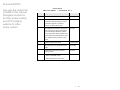
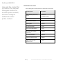
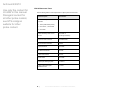
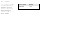
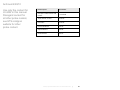
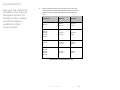
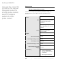
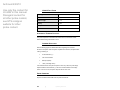
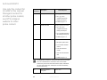
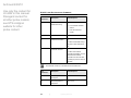
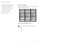
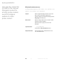
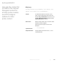
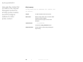
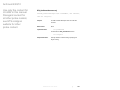
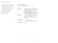
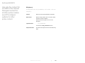
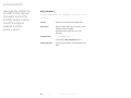
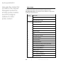
Revision Record
EMC Probes, MANUAL
|
Part #H-600100, Rev. G
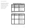
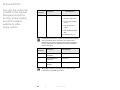
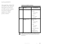
Revision
Description
Date
A
Initial Release
December, 2006
B
Added Appendix F: EC Declaration of
January, 2007
Conformity; updated descriptions of I and r
commands in Appendix E: Operating
Protocols; consistency/quality edits
C
Added FM5004 Field Monitor to Introduction;
April, 2007
added new sections, Typical Configurations
and HI-6153 Electric Field Probe; updated
photos, specifications, battery replacement in
HI-6053 Field Probe; added HI-6153 to Probe
Stand; updated service procedures, safety
notices
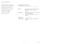
D
Updated H-491269 Probe Stand
November, 2007
E
Added information for HI-6022 and HI-6122
March, 2008
probes
F
Updated HI-6153 fiber optic connectors;
May, 2008
branding updates
G
• Added HI-4413USB content
October, 2009
• Added ETSProbe DLL User Guide
|
iii
Archived 6/29/10
Use only the content for
HI-4422 in this manual.
Disregard content for
all other probe models;
see ETS-Lindgren
website for other
probe content.
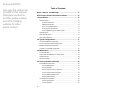
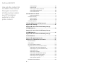
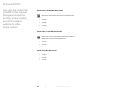
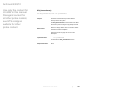
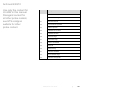
Table of Contents
Notes, Cautions, and Warnings ............................................... ix ETS-Lindgren Product Information Bulletin........................... ix 1.0 Introduction ........................................................................ 11 Readout Options .......................................................................................... 12 HI-6100 Field Monitor .......................................................................... 12 FM5004 Field Monitor .......................................................................... 12 HI-6113 Laser Data Interface .............................................................. 13 HI-4413P Fiber Optic Modem .............................................................. 13 HI-4413USB Fiber Optic to USB Converter ......................................... 14 Optional Tripod ............................................................................................ 14 Optional Probe Stand .................................................................................. 15 About Probe Operation ................................................................................ 16 2.0 Typical Configurations ...................................................... 17 HI-6100 Field Monitor Configuration ............................................................ 18 HI-6113 Laser Data Interface Configuration ................................................ 19 FM5004 Field Monitor Configuration ........................................................... 20 HI-4413P / HI-4413USB Configuration ........................................................ 21 3.0 Maintenance ....................................................................... 23 Annual Calibration ....................................................................................... 23 Laser Probes and Maintenance of Fiber Optics .......................................... 24 Upgrade Policies .......................................................................................... 24 Service Procedures ..................................................................................... 24 4.0 Laser-Powered Field Probes ............................................ 25 HI-6122 Electric Field Probe ........................................................................ 26 HI-6122 Specifications ......................................................................... 26 HI-6122 Operation ............................................................................... 27 HI-6122 Typical Frequency Response ................................................ 28 HI-6122 Typical Isotropic Response .................................................... 29 HI-6122 Additional Maintenance.......................................................... 30 HI-6122 Additional Parts ...................................................................... 30 HI-6153 Electric Field Probe ........................................................................ 32 HI-6153 Specifications ......................................................................... 32 HI-6153 Operation ............................................................................... 34 iv
|
Archived 6/29/10
Use only the content for
HI-4422 in this manual.
Disregard content for
all other probe models;
see ETS-Lindgren
website for other
probe content.
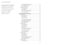
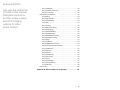
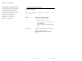
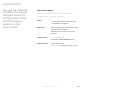
HI-6153 Typical Frequency Response ................................................ 35 HI-6153 Additional Maintenance.......................................................... 35 HI-6153 Additional Parts ...................................................................... 36 HI-6105 Electric Field Probe ........................................................................ 37 HI-6105 Specifications ......................................................................... 37 HI-6105 Operation ............................................................................... 38 HI-6105 Typical Frequency Response ................................................ 39 HI-6105 Additional Maintenance.......................................................... 39 HI-6105 Additional Parts ...................................................................... 40 5.0 Battery-Operated Field Probes ......................................... 41 HI-6022 Field Probe ..................................................................................... 42 HI-6022 Specifications ......................................................................... 42 HI-6022 Operation ............................................................................... 43 HI-6022 Power Switch ......................................................................... 44 HI-6022 Typical Frequency Response ................................................ 45 HI-6022 Typical Isotropic Response .................................................... 46 HI-6022 Additional Maintenance.......................................................... 46 HI-6022 Additional Parts ...................................................................... 47 HI-6053 Field Probe ..................................................................................... 49 HI-6053 Specifications ......................................................................... 49 HI-6053 Operation ............................................................................... 51 HI-6053 Power Switch ......................................................................... 52 HI-6053 Controls.................................................................................. 53 HI-6053 Typical Frequency Response ................................................ 53 HI-6053 Additional Maintenance.......................................................... 54 HI-6053 Battery Replacement ............................................................. 54 HI-6053 Additional Parts ...................................................................... 56 HI-6005 Field Probe ..................................................................................... 58 HI-6005 Specifications ......................................................................... 58 HI-6005 Operation ............................................................................... 59 HI-6005 Power Switch ......................................................................... 60 HI-6005 Typical Frequency Response ................................................ 61 HI-6005 Additional Maintenance.......................................................... 61 HI-6005 Additional Parts ...................................................................... 62 HI-4422 Field Probe ..................................................................................... 63 HI-4422 Specifications ......................................................................... 63 |
v
Archived 6/29/10
Use only the content for
HI-4422 in this manual.
Disregard content for
all other probe models;
see ETS-Lindgren
website for other
probe content.
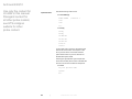
HI-4422 Operation ............................................................................... 65 HI-4422 Controls.................................................................................. 66 HI-4422 Typical Frequency Response ................................................ 67 HI-4422 Additional Maintenance.......................................................... 68 HI-4422 Additional Parts ...................................................................... 68 6.0 H-491269 Probe Stand ....................................................... 71 Probe Stand Dimensions ..................................................................... 71 Probe Stand Assembly ................................................................................ 72 Parts to Assemble................................................................................ 72 Steps to Assemble ............................................................................... 73 Probe Stand Operation ................................................................................ 76 7.0 Probe Shield Care and Replacement ............................... 79 Appendix A: Warranty ............................................................. 81 Appendix B: Series H-491198-01 Battery Charger
for NiMH Batteries.................................................................... 83 Appendix C: Series H-491198-48 Battery Charger
for NiMH Batteries.................................................................... 91 Appendix D: Series H-491198-36 Battery Charger
for NiCd Batteries .................................................................... 99 Appendix E: Operating Protocols ........................................ 105 Appendix F: ETSProbe DLL User Guide.............................. 117 About Redistribution .................................................................................. 117 Getting Started ........................................................................................... 117 DLL Function Calling Conventions ............................................................ 118 Supported Probes and Communications Protocols ................................... 118 Probe Family HI-Any (Auto Probe Detector)...................................... 122 Probe Family FP-Any (Auto Probe Detector FP) ............................... 122 Probe Family Virtual .......................................................................... 122 Probe Family HI-44xx MS .................................................................. 123 Probe Family HI-6005 MS (Medium Speed) ...................................... 123 Probe Family HI-6005 HS (High Speed)............................................ 124 Probe Family Laser HS (High Speed) ............................................... 124 Probe Types Not Supported .............................................................. 124 Quick Start Function Reference ................................................................. 125 vi
|
Archived 6/29/10
Use only the content for
HI-4422 in this manual.
Disregard content for
all other probe models;
see ETS-Lindgren
website for other
probe content.
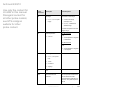
ETS_CreateProbe() ........................................................................... 125 ETS_ReadFieldSynchronous() .......................................................... 128 ETS_RemoveProbe() ........................................................................ 129 Advanced Function Reference .................................................................. 130 ETS_Battery() .................................................................................... 130 ETS_CalibrationDate()....................................................................... 131 ETS_CombinedField() ....................................................................... 132 ETS_Field()........................................................................................ 133 ETS_Firmware() ................................................................................ 134 ETS_GetErrorDescription()................................................................ 135 ETS_GetUnitsString() ........................................................................ 136 ETS_InitiateReadBattery() ................................................................. 137 ETS_InitiateReadField() .................................................................... 138 ETS_InitiateReadTemperature()........................................................ 139 ETS_IsOperationComplete() ............................................................. 140 ETS_Model()...................................................................................... 141 ETS_ProbeName() ............................................................................ 142 ETS_ReadBatterySynchronous() ...................................................... 143 ETS_ReadTemperatureSynchronous() ............................................. 144 ETS_SerialNumber() ......................................................................... 145 ETS_SetRange() ............................................................................... 146 ETS_SetUnits() .................................................................................. 147 ETS_TemperatureC() ........................................................................ 148 ETS_LaserCurrent() .......................................................................... 149 ETS_Version() ................................................................................... 150 ETS_SupplyVoltage() ........................................................................ 151 ETS_LaserTemperature() .................................................................. 152 ETS_ZeroProbe() .............................................................................. 153 Status Codes ............................................................................................. 154 Appendix G: EC Declaration of Conformity ........................ 157 |
vii
Archived 6/29/10
Use only the content for
HI-4422 in this manual.
Disregard content for
all other probe models;
see ETS-Lindgren
website for other
probe content.
This page intentionally left blank.
viii |
Archived 6/29/10
Use only the content for
HI-4422 in this manual.
Disregard content for
all other probe models;
see ETS-Lindgren
website for other
probe content.
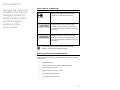
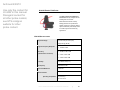
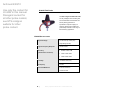
Notes, Cautions, and Warnings
Note: Denotes helpful information intended to
provide tips for better use of the product.
Caution: Denotes a hazard. Failure to follow
instructions could result in minor personal injury
and/or property damage. Included text gives proper
procedures.
Warning: Denotes a hazard. Failure to follow
instructions could result in SEVERE personal injury
and/or property damage. Included text gives proper
procedures.
See the ETS-Lindgren Product Information Bulletin for safety,
regulatory, and other product marking information.
ETS-Lindgren Product Information Bulletin
See the ETS-Lindgren Product Information Bulletin included with your shipment
for the following:
•
Warranty information
•
Safety, regulatory, and other product marking information
•
Steps to receive your shipment
•
Steps to return a component for service
•
ETS-Lindgren calibration service
•
ETS-Lindgren contact information
|
ix
Archived 6/29/10
Use only the content for
HI-4422 in this manual.
Disregard content for
all other probe models;
see ETS-Lindgren
website for other
probe content.
This page intentionally left blank.
x
|
Archived 6/29/10
Use only the content for
HI-4422 in this manual.
Disregard content for
all other probe models;
see ETS-Lindgren
website for other
probe content.
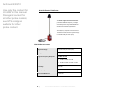
1.0 Introduction
The ETS-Lindgren EMC Field Probes embody the latest innovations in isotropic
sensor design and low-noise, miniaturized electronics. Each probe is a fully
intelligent sensor enabling fast and accurate EMF measurements with
industry-leading performance specifications. Optical coupling to a variety of
readout options makes these probes ideally suited for a wide range of field
monitoring applications.
The EMC field probes include laser-powered (laser) probes and battery-operated
probes. This manual includes operating information and specifications for these
probe models:
Laser-Powered
• HI-6122
• HI-6153
• HI-6105
Battery-Operated
• HI-6022
• HI-6053
• HI-6005
• HI-4422
Introduction
|
11
Archived 6/29/10
Use only the content for
HI-4422 in this manual.
Disregard content for
all other probe models;
see ETS-Lindgren
website for other
probe content.
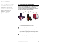
Readout Options
HI-6100 FIELD MONITOR
The HI-6100 Field Monitor accepts inputs from up to any four probes, and
analyzes and displays information on a user-configurable LCD.
The HI-6100 may be used in
conjunction with both the laser
and battery-operated probes.
HI-6100 Field Monitor
For information on using the HI-6100 with ETS-Lindgren probes, see HI-6100
Field Monitor Configuration on page 18.
FM5004 FIELD MONITOR
The FM5004 Field Monitor accepts inputs from up to any four probes, and
analyzes and displays information on a user-configurable LCD.
The FM5004 may be
used in conjunction with
the battery-operated
probes.
FM5004 Field Monitor
For information on using the FM5004 with ETS-Lindgren probes, see FM5004
Field Monitor Configuration on page 20.
12
|
Introduction
Archived 6/29/10
Use only the content for
HI-4422 in this manual.
Disregard content for
all other probe models;
see ETS-Lindgren
website for other
probe content.
HI-6113 LASER DATA INTERFACE
The laser probes and the
HI-6113 Laser Data
Interface together
communicate with
ProbeView™ Laser
software through a USB
port on the computer.
HI-6113 Laser Data Interface
For information on using the HI-6113 with ETS-Lindgren probes, see HI-6113
Laser Data Interface Configuration on page 19.
HI-4413P FIBER OPTIC MODEM
The battery-powered probes use the
HI-4413P Fiber Optic Modem to
communicate with ProbeView II™
software through a serial port on the
computer.
HI-4413P Fiber Optic Modem
For information on using the HI-4413P with ETS-Lindgren probes, see
HI-4413P / HI-4413USB Configuration on page 21.
Introduction
|
13
Archived 6/29/10
Use only the content for
HI-4422 in this manual.
Disregard content for
all other probe models;
see ETS-Lindgren
website for other
probe content.
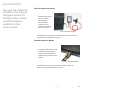
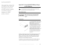
HI-4413USB FIBER OPTIC TO USB CONVERTER
The battery-powered
probes use the HI-4413
Fiber Optic to USB
Converter to communicate
with ProbeView II™
software through a USB
port on the computer.
HI-4413USB Fiber Optic to USB Converter
For information on using the HI-4413USB with ETS-Lindgren probes, see
HI-4413P / HI-4413USB Configuration on page 21.
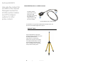
Optional Tripod
The H-491009 Dielectric Tripod is the
preferred method for mounting field probes
for making unperturbed field
measurements. It provides stable
placement for one probe, and includes a
1/4–20 UNC threaded stud for mounting
any ETS-Lindgren probe with a tripod
mount. It is designed with an adjustable
center post and a rotating mount.
14
|
Introduction
Archived 6/29/10
Use only the content for
HI-4422 in this manual.
Disregard content for
all other probe models;
see ETS-Lindgren
website for other
probe content.
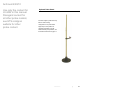
Optional Probe Stand
The ETS-Lindgren probe stand may
also be used in testing
configurations. The probe stand
supports up to two probes. For
complete information on probe
stand assembly and operation, see
H-491269 Probe Stand on page 71.
Introduction
|
15
Archived 6/29/10
Use only the content for
HI-4422 in this manual.
Disregard content for
all other probe models;
see ETS-Lindgren
website for other
probe content.
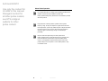
About Probe Operation
For complete information on setting up and operating the field monitor,
software, and other devices available for the laser and
battery-operated field probes, please see the documentation provided
with those products.
Field probes are nominally rated for operation within a specific
frequency range, but may also respond to signals above and below
those frequencies. A probe may exhibit response to frequencies below
the lower end of the range, and may also respond to frequencies
above the upper end of the range, though not consistently or
predictably.
Keep all conductive objects away from laser-powered and
battery-operated probes. Conductive objects in the proximity of the
probe can distort the near field and compromise measurement
accuracy. If the application requires measurements from a fixed
position, always mount the probe on a non-metallic platform, using
non-metallic screws.
16
|
Introduction
Archived 6/29/10
Use only the content for
HI-4422 in this manual.
Disregard content for
all other probe models;
see ETS-Lindgren
website for other
probe content.
2.0 Typical Configurations
A variety of configurations are available with the field monitors, probes, and other
devices. Following are typical examples of how the components can be
assembled to accommodate most testing environments.
Typical Configurations
|
17
Archived 6/29/10
Use only the content for
HI-4422 in this manual.
Disregard content for
all other probe models;
see ETS-Lindgren
website for other
probe content.
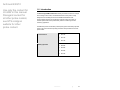
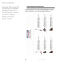
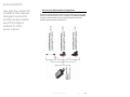
HI-6100 Field Monitor Configuration
The following diagram illustrates the ETS-Lindgren probes that may be used with
the HI-6100 Field Monitor. In the diagram, the FM in HI-6153FM, for example,
refers to Field Monitor Kit. As a kit, the probe includes an interface card.
18
|
Typical Configurations
Archived 6/29/10
Use only the content for
HI-4422 in this manual.
Disregard content for
all other probe models;
see ETS-Lindgren
website for other
probe content.
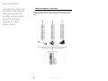
HI-6113 Laser Data Interface Configuration
The following diagram illustrates the ETS-Lindgren probes that may be used with
the HI-6113 Laser Data Interface (LDI). In the diagram, the USB in HI-6153USB,
for example, refers to USB Kit. As a kit, the probe includes all components
required to operate the probe with the HI-6113.
Typical Configurations
|
19
Archived 6/29/10
Use only the content for
HI-4422 in this manual.
Disregard content for
all other probe models;
see ETS-Lindgren
website for other
probe content.
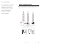
FM5004 Field Monitor Configuration
The following diagram illustrates the ETS-Lindgren probes that may be used with
the FM5004 Field Monitor. The probes are shipped with a 10-meter fiber optic
cable.
20
|
Typical Configurations
Archived 6/29/10
Use only the content for
HI-4422 in this manual.
Disregard content for
all other probe models;
see ETS-Lindgren
website for other
probe content.
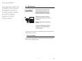
HI-4413P / HI-4413USB Configuration
The following diagram illustrates the ETS-Lindgren probes that may be used with
the HI-4413P Fiber Optic Modem or the HI-4413USB Fiber Optic to USB
Converter.
Typical Configurations
|
21
Archived 6/29/10
Use only the content for
HI-4422 in this manual.
Disregard content for
all other probe models;
see ETS-Lindgren
website for other
probe content.
This page intentionally left blank.
22
|
Typical Configurations
Archived 6/29/10
Use only the content for
HI-4422 in this manual.
Disregard content for
all other probe models;
see ETS-Lindgren
website for other
probe content.
3.0 Maintenance
Before performing any maintenance,
follow the safety information in the
ETS-Lindgren Product Information
Bulletin included with your shipment.
Maintenance of probes is limited to
WARRANTY
external components such as cables or
connectors.
Warranty may be void if the housing is
opened.
If you have any questions concerning
maintenance, contact ETS-Lindgren
Customer Service.
If you have an HI-6105, HI-6005, or HI-4422 Field Probe, see Probe Shield Care
and Replacement on page 79.
Annual Calibration
See the Product Information Bulletin included with your shipment for information
on ETS-Lindgren calibration services.
Maintenance
|
23
Archived 6/29/10
Use only the content for
HI-4422 in this manual.
Disregard content for
all other probe models;
see ETS-Lindgren
website for other
probe content.
Laser Probes and Maintenance of Fiber Optics
The fiber optic connectors and cables used with laser-powered probes can be
damaged from airborne particles, humidity and moisture, oils from the human
body, and debris from the connectors they plug into. Always handle connectors
and cables with care, using the following guidelines.
Before performing any maintenance, disconnect
the fiber optic cables from the unit and turn off
power.
When disconnecting fiber optic cables, apply the
included dust caps to the ends to maintain their
integrity.
Before connecting fiber optic cables, clean the
connector tips and in-line connectors.
Before attaching in-line connectors, clean them
with moisture-free compressed air.
Failure to perform these tasks may result in
damage to the fiber optic connectors or cables.
Upgrade Policies
Periodically, probes are upgraded to enhance functionality. Contact
ETS-Lindgren Customer Service for the upgrade status of your probe.
Service Procedures
For the steps to return a system or system component to ETS-Lindgren for
service, see the Product Information Bulletin included with your shipment.
24
|
Maintenance
Archived 6/29/10
Use only the content for
HI-4422 in this manual.
Disregard content for
all other probe models;
see ETS-Lindgren
website for other
probe content.
4.0 Laser-Powered Field Probes
The HI-61XX Series LaserPro™ Field Probe is a laser-powered probe, an
excellent tool for electric field mapping, industrial monitoring, and EMC field
measurements.
The HI-61XX Series probes contain a photo-voltaic converter that provides power
to the probe circuitry when sufficient light power is received by the converter. The
light power is generated by a laser in the HI-6113 Laser Data Interface (LDI), and
is transmitted to the converter through an optical fiber in the duplex fiber optic
cable. The probe communicates with the HI-6113 through this fiber optic cable.
Receiving power from the HI-6113 allows for unlimited test times.
The probe system incorporates a safety interlock mechanism that turns off the
laser if the HI-6113 does not receive data from the probe within a specified time
frame. The safety mechanism is intended to prevent injury from the laser if the
HI-6113 issues a command to turn on the laser while the fiber optic cables are
disconnected, improperly connected, cut, or damaged.
The HI-6100 Field Monitor may also be used with the HI-61XX Series Field
Probe for RFI/EMC testing.
The basic probe is shipped with an attached one-meter fiber optic cable, a
10-meter fiber extension cable, a carrying case, a battery charger, and
connectors that extend the length of the fiber optic cable.
Laser-Powered Field Probes
|
25
Archived 6/29/10
Use only the content for
HI-4422 in this manual.
Disregard content for
all other probe models;
see ETS-Lindgren
website for other
probe content.
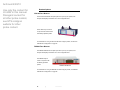
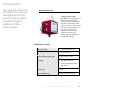
HI-6122 Electric Field Probe
The ETS-Lindgren HI-6122 Field Probe
provides broadband frequency coverage
and wide dynamic range that satisfies the
demands of most test requirements.
The frequency response of the HI-6122 is
10 kHz to 1 GHz, and the dynamic range is
2 to 800 Volts per meter (V/m).
HI-6122 SPECIFICATIONS
Dynamic Range:
2.0 – 800 Volts per meter (V/m)
Ranges:
Single
Typical Frequency Response:
10 kHz–1 GHz
• 10 kHz–30 kHz -2.5 / +0.5 dB
• 30 kHz–1 GHz ±1 dB
Linearity:
±0.5 dB
Isotropicity:
±0.5 dB
Overload Withstand:
> 1,500 V/m CW
Environmental
Operating Temperature:
10°C to 40°C
50°F to 104°F
Humidity:
5% to 95% relative humidity,
non-condensing
26
|
Laser-Powered Field Probes: HI-6122 Electric Field Probe
Archived 6/29/10
Use only the content for
HI-4422 in this manual.
Disregard content for
all other probe models;
see ETS-Lindgren
website for other
probe content.
Fiber Optic Cable Connector:
Two fiber optic connectors mounted on
the housing:
• FC for laser
• ST for transmitter
Probe Mount:
1/4–20 UNC tapped hole (internal thread)
Dimensions:
Housing:
32 mm x 32 mm x 32 mm
1.26 in x 1.26 in x 1.26 in
Probe Shields:
Weight:
43 mm (1.69 in)
80 g (2.82 oz)
HI-6122 OPERATION
The HI-6122 can be used with the HI-6100 Field Monitor. It can also be
connected to a personal computer using an optional HI-6113 Laser Data
Interface (LDI) and ProbeView™ Laser software.
The HI-6122 is a true 3-axis probe. When requested, X, Y, Z, and total field data
can be reported.
For a list and description of communication and information transfer protocols,
including command structure, probe commands, and HI-6113 commands, see
Appendix E: Operating Protocols on page 105.
Laser-Powered Field Probes: HI-6122 Electric Field Probe
|
27
Archived 6/29/10
Use only the content for
HI-4422 in this manual.
Disregard content for
all other probe models;
see ETS-Lindgren
website for other
probe content.
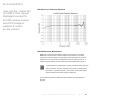
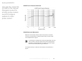
HI-6122 TYPICAL FREQUENCY RESPONSE
28
|
Laser-Powered Field Probes: HI-6122 Electric Field Probe
Archived 6/29/10
Use only the content for
HI-4422 in this manual.
Disregard content for
all other probe models;
see ETS-Lindgren
website for other
probe content.
HI-6122 TYPICAL ISOTROPIC RESPONSE
Isotropic response measured in a 20 V/m field at 400 MHz.
Laser-Powered Field Probes: HI-6122 Electric Field Probe
|
29
Archived 6/29/10
Use only the content for
HI-4422 in this manual.
Disregard content for
all other probe models;
see ETS-Lindgren
website for other
probe content.
HI-6122 ADDITIONAL MAINTENANCE
Maintenance of the HI-6122 is limited to external components such as cables,
connectors, and probe shields. For information on fiber optic cable and connector
maintenance, see Laser Probes and Maintenance of Fiber Optics on page 24. To
replace the probe shields, see Probe Shield Care and Replacement on page 79.
Any maintenance or calibration task requires probe disassembly,
which may void your warranty. Only ETS-Lindgren service personnel
should perform these tasks. To avoid problems with your warranty,
contact ETS-Lindgren Customer Service before performing any
maintenance.
For complete information on maintenance and calibration, see Maintenance on
page 23.
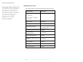
HI-6122 ADDITIONAL PARTS
Use the following table to order replacement or optional parts for the HI-6122.
Part Description
Part Number
Probe shield replacement Kit
112955
includes:
• Three probe shields (cones)
• One each X, Y, and Z label
• Six screws
30
Cable Assembly, Fiber, FC-FC,
H-491263-xx
ST-ST
(xx=length in meters)
FC to FC Inline Connector
H-23861521000
ST to ST Inline Connector
708027
Carrying Case
H-491291
HI-6100 Field Monitor
HI-6100
|
Laser-Powered Field Probes: HI-6122 Electric Field Probe
Archived 6/29/10
Use only the content for
HI-4422 in this manual.
Disregard content for
all other probe models;
see ETS-Lindgren
website for other
probe content.
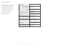
Part Description
Part Number
Laser Data Interface
HI-6113
Tripod, Dielectric
H-491009
Probe Stand
H-491269
Fiber Optic Cleaning System
H-34FO1
Laser System Fiber Optic
112333
Maintenance Kit
Laser-Powered Field Probes: HI-6122 Electric Field Probe
|
31
Archived 6/29/10
Use only the content for
HI-4422 in this manual.
Disregard content for
all other probe models;
see ETS-Lindgren
website for other
probe content.
HI-6153 Electric Field Probe
The ETS-Lindgren HI-6153 Field Probe
provides broadband frequency coverage
and wide dynamic range that satisfies the
demands of most test requirements.
The frequency response of the HI-6153 is
10 MHz to 40 GHz, and the dynamic range
is 2 to 800 Volts per meter (V/m).
HI-6153 SPECIFICATIONS
Dynamic Range:
2.0–800 Volts per meter (V/m)
Ranges:
Single
Typical Frequency Response:
10 MHz–40 GHz
• 10 MHz–18 GHz ±2.5 dB
• 18 GHz–40 GHz +2.0 dB / -4.0 dB
32
Linearity:
±0.5 dB
Isotropicity:
±1.0 dB
Overload Withstand:
1,500 V/m
|
Laser-Powered Field Probes: HI-6153 Electric Field Probe
Archived 6/29/10
Use only the content for
HI-4422 in this manual.
Disregard content for
all other probe models;
see ETS-Lindgren
website for other
probe content.
Environmental
Operating Temperature:
10°C to 40°C
50°F to 104°F
Humidity:
5% to 95% relative humidity,
non-condensing
Physical Interface:
• Duplex optical fiber
(62.5 micron multimode)
• FC connectors for laser cable,
integral 1-m optical cable
• ST connector for transmitter cable,
integral 1-m optical cable
Probe Mount:
1/4–20 UNC tapped hole (internal thread)
Dimensions
Probe Length:
432 mm (17.0 in)
(includes electronics housing)
Probe Diameter:
Weight:
102 mm (4.0 in)
0.54 kg (19 oz)
Laser-Powered Field Probes: HI-6153 Electric Field Probe
|
33
Archived 6/29/10
Use only the content for
HI-4422 in this manual.
Disregard content for
all other probe models;
see ETS-Lindgren
website for other
probe content.
HI-6153 OPERATION
The HI-6153 assembly consists
of a pyramidal casing containing
the sensor, which is mounted on
one end of a shaft. The other
end of the shaft is attached to
an extrusion that houses the
electronics. The sensor and
electronics housing operate and
are calibrated as a unit.
The HI-6153 is a true 3-axis
probe. When requested, X, Y, Z,
and total field data can be
reported.
The HI-6153 can be used with
the HI-6100 Field Monitor. It can
also be connected to a personal
computer using an optional
HI-6113 Laser Data
Interface (LDI) and
ProbeView™ Laser software.
For a list and description of communication and information transfer protocols,
including command structure, probe commands, and HI-6113 commands, see
Appendix E: Operating Protocols on page 105.
34
|
Laser-Powered Field Probes: HI-6153 Electric Field Probe
Archived 6/29/10
Use only the content for
HI-4422 in this manual.
Disregard content for
all other probe models;
see ETS-Lindgren
website for other
probe content.
HI-6153 TYPICAL FREQUENCY RESPONSE
HI-6153 ADDITIONAL MAINTENANCE
Maintenance of the HI-6153 is limited to external components such as cables
and connectors. For information on fiber optic cable and connector maintenance,
see Laser Probes and Maintenance of Fiber Optics on page 24.
Any maintenance or calibration task requires probe disassembly, which may
void your warranty. Only ETS-Lindgren service personnel should perform
these tasks. To avoid problems with your warranty, contact ETS-Lindgren
Customer Service before performing any maintenance.
For complete information on maintenance and calibration, see Maintenance on
page 23.
Laser-Powered Field Probes: HI-6153 Electric Field Probe
|
35
Archived 6/29/10
Use only the content for
HI-4422 in this manual.
Disregard content for
all other probe models;
see ETS-Lindgren
website for other
probe content.
HI-6153 ADDITIONAL PARTS
Use the following table to order replacement or optional parts for the HI-6153.
Part Description
Part Number
Cable Assembly, Fiber, FC-FC,
H-491263-xx
ST-ST
(xx=length in meters)
FC to FC Inline Connector
H-23861521000
ST to ST Inline Connector
708027
Carrying Case
H-491291
HI-6100 Field Monitor
HI-6100
HI-6113 Laser Data Interface
HI-6113
H-491009 Tripod, Dielectric,
H-491009
Field Probe
H-491269 Probe Stand
H-491269
Fiber Optic Cleaning System
H-34FO1
Laser System Fiber Optic
112333
Maintenance Kit
36
|
Laser-Powered Field Probes: HI-6153 Electric Field Probe
Archived 6/29/10
Use only the content for
HI-4422 in this manual.
Disregard content for
all other probe models;
see ETS-Lindgren
website for other
probe content.
HI-6105 Electric Field Probe
The ETS-Lindgren HI-6105 Electric
Field Probe is a fully intelligent sensor
enabling fast and accurate
EMF measurements with industryleading performance specifications.
Optical coupling to a variety of readout
options makes this probe ideally suited
for a wide range of field monitoring
applications.
HI-6105 SPECIFICATIONS
Dynamic Range:
0.5–800 Volts per meter (V/m)
Single Range (64 dB)
Typical Frequency Response:
• 100 kHz–6 GHz
Accuracy
• 26 MHz–2 GHz ±1dB
(Values before correction):
• 2 GHz–4 GHz ±2dB
• 4 GHz–6 GHz ±3dB
Linearity:
±0.5 dB full scale (F.S.)
Isotropicity:
400 MHz ±0.5 dB
Overload Withstand:
1,500 V/m
Environmental:
Operating Temperature
10°C to 40°C
50°F to 104°F
Laser-Powered Field Probes: HI-6105 Electric Field Probe
|
37
Archived 6/29/10
Use only the content for
HI-4422 in this manual.
Disregard content for
all other probe models;
see ETS-Lindgren
website for other
probe content.
Humidity
5% to 95% relative humidity,
non-condensing
Physical Interface:
• Duplex optical fiber
(62.5 micron multimode)
• FC connectors for laser cable,
integral 1-m optical cable
• ST connector for transmitter cable,
integral 1-m optical cable
Dimensions:
32 mm (1.25 in) cube with probe shields
on three sides
Probe Mount:
1/4–20 UNC (internal thread)
Weight:
0.08 kg (2.6 oz.)
HI-6105 OPERATION
The HI-6105 can be used with the HI-6100 Field Monitor. It can also be
connected to a personal computer using an optional HI-6113 Laser Data
Interface (LDI) and ProbeView™ Laser software.
For a list and description of communication and information transfer protocols,
including command structure, probe commands, and HI-6113 commands, see
Appendix E: Operating Protocols on page 105.
38
|
Laser-Powered Field Probes: HI-6105 Electric Field Probe
Archived 6/29/10
Use only the content for
HI-4422 in this manual.
Disregard content for
all other probe models;
see ETS-Lindgren
website for other
probe content.
HI-6105 TYPICAL FREQUENCY RESPONSE
HI-6105 ADDITIONAL MAINTENANCE
Maintenance of the HI-6105 is limited to external components such as cables,
connectors, and probe shields. For information on fiber optic cable and connector
maintenance, see Laser Probes and Maintenance of Fiber Optics on page 24. To
replace the probe shields, see Probe Shield Care and Replacement on page 79.
Any maintenance or calibration task requires probe disassembly, which may
void your warranty. Only ETS-Lindgren service personnel should perform
these tasks. To avoid problems with your warranty, contact ETS-Lindgren
Customer Service before performing any maintenance.
For complete information on maintenance and calibration, see Maintenance on
page 23.
Laser-Powered Field Probes: HI-6105 Electric Field Probe
|
39
Archived 6/29/10
Use only the content for
HI-4422 in this manual.
Disregard content for
all other probe models;
see ETS-Lindgren
website for other
probe content.
HI-6105 ADDITIONAL PARTS
Use the following tables to order replacement or optional parts for the HI-6105.
Part Description
Part Number
Probe shield replacement Kit
H-491237
includes:
• Three probe shields (cones)
• One each X, Y, and Z label
• Six screws
Cable Assembly, Fiber, FC-FC,
H-491263-xx
ST-ST
(xx=length in meters)
FC to FC Inline Connector
H-23861521000
ST to ST Inline Connector
708027
Tripod, Dielectric
H-491009
HI-6100 Field Monitor
HI-6100
Laser Data Interface
HI-6113
Probe Stand
H-491269
Fiber Optic Cleaning System
H-34FO1
Laser System Fiber Optic
112333
Maintenance Kit
40
|
Laser-Powered Field Probes: HI-6105 Electric Field Probe
Archived 6/29/10
Use only the content for
HI-4422 in this manual.
Disregard content for
all other probe models;
see ETS-Lindgren
website for other
probe content.
5.0 Battery-Operated Field Probes
Before using your battery-operated probe, read the following:
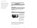
HI-6053 Field Probe: Appendix B: Series H-491198-01 Battery
Charger on page 83.
HI-6022 and HI-6005 Field Probe: Appendix C: Series H-491198-48
Battery Charger on page 91.
HI-4422 Field Probe: Appendix D: Series H-491198-36 Battery
Charger on page 99.
To calibrate the probe prior to shipment, ETS-Lindgren also charges
the internal battery at the factory. Every effort is made to make sure
that the probe arrives ready to use, but you should verify the condition
of the battery prior to making any measurements.
The battery-operated probes utilize three orthogonal sensors to provide an
isotropic reading of the electric field. When requested, X, Y, Z, and total field data
can be reported, making the ETS-Lindgren battery-operated probes true 3-axis
probes.
Battery-Operated Field Probes
|
41
Archived 6/29/10
Use only the content for
HI-4422 in this manual.
Disregard content for
all other probe models;
see ETS-Lindgren
website for other
probe content.
HI-6022 Field Probe
The ETS-Lindgren HI-6022 Field Probe
provides broadband frequency coverage
and wide dynamic range that satisfies the
demands of most test requirements.
The frequency response of the HI-6022 is
10 kHz to 1 GHz, and the dynamic range is
2 to 800 Volts per meter (V/m).
HI-6022 SPECIFICATIONS
Dynamic Range:
2.0–800 Volts per meter (V/m)
Ranges:
Single
Typical Frequency Response:
10 kHz–1 GHz
• 10 kHz–30 kHz -2.5 / +0.5 dB
• 30 kHz–1 GHz ±1 dB
Linearity:
±0.5 dB
Isotropicity:
±0.5 dB
Overload Withstand:
> 1,500 V/m CW
Environmental
Operating Temperature:
10°C to 40°C
50°F to 104°F
Humidity:
5% to 95% relative humidity,
non-condensing
42
|
Battery-Operated Field Probes: HI-6022 Field Probe
Archived 6/29/10
Use only the content for
HI-4422 in this manual.
Disregard content for
all other probe models;
see ETS-Lindgren
website for other
probe content.
Fiber Optic Cable Connector:
Standard FSMA
Battery:
Rechargeable Nickel-Metal Hydride
(NiMH)
Battery Life:
Up to 8 hours
Battery Charger:
• 100–240 VAC universal input
• 2-hour charge from full depletion
Probe Mount:
1/4–20 UNC tapped hole (internal thread)
Dimensions:
Housing:
32 mm x 32 mm x 32 mm
1.26 in x 1.26 in x 1.26 in
Probe Shields:
Weight:
43 mm (1.69 in)
80 g (2.82 oz)
HI-6022 OPERATION
The HI-6022 can be used with the HI-6100 Field Monitor or the FM5004 Field
Monitor. It can also be connected to a personal computer using an optional
HI-4413P Fiber Optic Modem or HI-4413USB Fiber Optic to USB Converter and
ProbeView II™ software.
The HI-6022 is a true 3-axis probe. When requested, X, Y, Z, and total field data
can be reported.
For a list and description of communication and information transfer protocols,
including command structure and probe commands, see Appendix E: Operating
Protocols on page 105.
Battery-Operated Field Probes: HI-6022 Field Probe
|
43
Archived 6/29/10
Use only the content for
HI-4422 in this manual.
Disregard content for
all other probe models;
see ETS-Lindgren
website for other
probe content.
HI-6022 POWER SWITCH
The power switch activates and deactivates the HI-6022:
•
ON (I)—When the power switch is in the I position, an internal 4.8 VDC
Nickel-Metal Hydride (NiMH) battery provides power to the probe, and
the power indicator LED blinks.
•
OFF (0)—When the power switch is in the O position, the probe is
inactive. To prolong battery life, set the switch to OFF when the probe
is not in use.
44
|
Battery-Operated Field Probes: HI-6022 Field Probe
Archived 6/29/10
Use only the content for
HI-4422 in this manual.
Disregard content for
all other probe models;
see ETS-Lindgren
website for other
probe content.
HI-6022 TYPICAL FREQUENCY RESPONSE
Battery-Operated Field Probes: HI-6022 Field Probe
|
45
Archived 6/29/10
Use only the content for
HI-4422 in this manual.
Disregard content for
all other probe models;
see ETS-Lindgren
website for other
probe content.
HI-6022 TYPICAL ISOTROPIC RESPONSE
Isotropic response measured in a 20 V/m field at 400 MHz.
HI-6022 ADDITIONAL MAINTENANCE
Maintenance of the HI-6005 is limited to external components such as cables,
connectors, and probe shields. To replace the probe shields, see Probe Shield
Care and Replacement on page 79.
46
|
Battery-Operated Field Probes: HI-6022 Field Probe
Archived 6/29/10
Use only the content for
HI-4422 in this manual.
Disregard content for
all other probe models;
see ETS-Lindgren
website for other
probe content.
Any maintenance or calibration task requires probe disassembly,
which may void your warranty. Only ETS-Lindgren service personnel
should perform these tasks. To avoid problems with your warranty,
contact ETS-Lindgren Customer Service before performing any
maintenance.
For complete information on maintenance and calibration, see Maintenance on
page 23.
HI-6022 ADDITIONAL PARTS
Use the following table to order replacement or optional parts for the HI-6022.
Optional Part Description
Part Number
Probe shield replacement Kit
112955
includes:
• Three probe shields (cones)
• One each X, Y, and Z label
• Six screws
H-491106-xx
Cable, Fiber Optic, Glass
(xx=length in meters)
Connector Set, two required
H-231205000
(Bulkhead Feedthru)
Fiber Optic Modem, RS-232
Interface
Fiber Optic to USB Converter, USB
Interface
HI-4413P
HI-4413USB
Battery Charger
H-491198-01
Carrying Case
H-491291
Tripod, Dielectric
H-491009
Battery-Operated Field Probes: HI-6022 Field Probe
|
47
Archived 6/29/10
Use only the content for
HI-4422 in this manual.
Disregard content for
all other probe models;
see ETS-Lindgren
website for other
probe content.
Optional Part Description
48
Part Number
HI-6100 Field Monitor
HI-6100
Graphical Readout
HI-4460
Probe Stand
H-491269
|
Battery-Operated Field Probes: HI-6022 Field Probe
Archived 6/29/10
Use only the content for
HI-4422 in this manual.
Disregard content for
all other probe models;
see ETS-Lindgren
website for other
probe content.
HI-6053 Field Probe
The ETS-Lindgren HI-6053 Field Probe
provides broadband frequency coverage
and wide dynamic range that satisfies the
demands of most test requirements.
The frequency response of the HI-6053
is 10 MHz to 40 GHz, and the dynamic
range is 2 to 800 Volts per meter (V/m).
HI-6053 SPECIFICATIONS
Dynamic Range:
2.0–00 Volts per meter (V/m)
Ranges:
Single
Typical Frequency Response:
10 MHz–0 GHz
• 10 MHz–8 GHz ±2.5 dB
• 18 GHz–0 GHz +2.0 dB / -4.0 dB
Linearity:
±0.5 dB
Isotropicity:
±1.0 dB
Overload Withstand:
1,500 V/m
Battery-Operated Field Probes: HI-6053 Field Probe
|
49
Archived 6/29/10
Use only the content for
HI-4422 in this manual.
Disregard content for
all other probe models;
see ETS-Lindgren
website for other
probe content.
Environmental:
Operating Temperature
10°C to 40°C
50°F to 104°F
Humidity
5% to 95% relative humidity,
non-condensing
Fiber Optic Cable Connector:
Standard FSMA
Battery:
Four AAA batteries, rechargeable
Nickel-Metal Hydride (NiMH)
Battery Charger:
115–230 VAC
Approximately three hours
Battery Life:
> 30 hours continuous (at full charge)
Probe Mount:
1/4–20 UNC tapped hole (internal thread)
Dimensions:
Probe Length
432 mm (17.0 in)
(includes electronics housing)
Probe Diameter
Weight
50
|
102 mm (4.0 in)
0.54 kg (19 oz)
Battery-Operated Field Probes: HI-6053 Field Probe
Archived 6/29/10
Use only the content for
HI-4422 in this manual.
Disregard content for
all other probe models;
see ETS-Lindgren
website for other
probe content.
HI-6053 OPERATION
The HI-6053 assembly consists of a
pyramidal casing containing the
sensor, which is mounted on one
end of a shaft. The other end of the
shaft is attached to an extrusion
that houses the electronics. The
sensor and electronics housing
operate and are calibrated as a
unit.
The HI-6053 is a true 3-axis probe.
When requested, X, Y, Z, and total
field data can be reported.
The HI-6053 can be used with the
HI-6100 Field Monitor or the
FM5004 Field Monitor. It can also
be connected to a personal
computer using an optional
HI-4413P Fiber Optic Modem or
HI-4413USB Fiber Optic to USB
Converter and ProbeView II™
software.
For a list and description of communication and information transfer protocols,
including command structure and probe commands, see Appendix E: Operating
Protocols on page 105.
Battery-Operated Field Probes: HI-6053 Field Probe
|
51
Archived 6/29/10
Use only the content for
HI-4422 in this manual.
Disregard content for
all other probe models;
see ETS-Lindgren
website for other
probe content.
HI-6053 POWER SWITCH
The power button that activates and deactivates the HI-6053 is located on the
bottom of the electronic housing. A green indicator light in the power button
flashes when the probe is on.
•
On—To turn the HI-6053 on, push in the power button, and then
release. The power button flashes a green indicator light when the
probe is on, and four AAA Nickel-Metal Hydride (NiMH) batteries
supply power.
•
Off—To turn the HI-6053 off, push in the power button, and then
release. The green indicator light stops flashing, indicating the probe is
off. When not in use, turn the probe off to prolong battery life.
52
|
Battery-Operated Field Probes: HI-6053 Field Probe
Archived 6/29/10
Use only the content for
HI-4422 in this manual.
Disregard content for
all other probe models;
see ETS-Lindgren
website for other
probe content.
HI-6053 CONTROLS
Two fiber optic connectors and a battery charger connector are mounted on the
HI-6053 housing.
HI-6053 TYPICAL FREQUENCY RESPONSE
Battery-Operated Field Probes: HI-6053 Field Probe
|
53
Archived 6/29/10
Use only the content for
HI-4422 in this manual.
Disregard content for
all other probe models;
see ETS-Lindgren
website for other
probe content.
HI-6053 ADDITIONAL MAINTENANCE
Maintenance of the HI-6053 is limited to external components such as cables or
connectors, and replacing the batteries. For complete information on replacing
the batteries, see the next section, HI-6053 Battery Replacement.
Any other maintenance or calibration task requires probe disassembly, which
may void your warranty. Only ETS-Lindgren service personnel should
perform these tasks. To avoid problems with your warranty, contact
ETS-Lindgren Customer Service before performing any maintenance.
For complete information on maintenance and calibration, see Maintenance on
page 23.
HI-6053 BATTERY REPLACEMENT
During the annual calibration of your HI-6053 at the ETS-Lindgren factory, the
batteries are tested to verify continued operability. If required, the batteries are
replaced at that time. It is rare that you should need to replace the batteries
between calibration checks, but in that event, follow these steps.
If you are not qualified to perform this procedure, please consult
ETS-Lindgren Customer Service. ETS-Lindgren is not responsible for
damage to the probe as a result of replacing the batteries.
See the Product Information Bulletin included with your shipment for
information on ETS-Lindgren calibration services.
1.
Turn the HI-6053 off. Verify that the green indicator light is not flashing.
2.
Carefully disconnect the fiber optic cables from the Transmit and
Receive connectors.
3.
Remove the four screws from the bottom of the electronics housing.
4.
Lift the bottom away from the housing. Wires from the power button
are connected to the internal circuitry, so carefully turn the bottom over
and place it to the side, avoiding placing stress on the wires.
54
|
Battery-Operated Field Probes: HI-6053 Field Probe
Archived 6/29/10
Use only the content for
HI-4422 in this manual.
Disregard content for
all other probe models;
see ETS-Lindgren
website for other
probe content.
5.
A single connector attaches the two boards together. Withdraw the two
boards from the housing at the same time. The boards should easily
slide out of the tracks.
6.
Detach the two boards by carefully separating them at the connector,
avoiding damage to the pins.
7.
Replace the four AAA rechargeable NiMH batteries, orienting the
+/- ends as indicated.
Battery-Operated Field Probes: HI-6053 Field Probe
|
55
Archived 6/29/10
Use only the content for
HI-4422 in this manual.
Disregard content for
all other probe models;
see ETS-Lindgren
website for other
probe content.
Recycle the used batteries, or dispose of them safely and properly.
Many cities collect used batteries for recycling or disposal. You may
contact your local waste disposal agency for information on battery
recycling and disposal.
8.
Reattach the two boards at the connector.
9.
Slide the two boards into the correct tracks inside the housing, and
carefully push them until they are completely recessed.
10. Replace the bottom of the housing, avoiding damage to the power
button wires.
11. Replace and tighten the four screws into the bottom of the housing.
HI-6053 ADDITIONAL PARTS
Use the following table to order replacement or optional parts for the HI-6053.
Optional Part Description
Part Number
H-491106-xx
Cable, Fiber Optic, Glass
(xx=length in meters)
Connector Set, two required
H-231205000
(Bulkhead Feedthru)
Fiber Optic / RS232 Interface
Fiber Optic to USB Converter, USB
Interface
56
HI-4413P
HI-4413USB
Battery Charger
H-491198-01
Carrying Case
H-491291
Tripod, Dielectric
H-491009
HI-6100 Field Monitor
HI-6100
|
Battery-Operated Field Probes: HI-6053 Field Probe
Archived 6/29/10
Use only the content for
HI-4422 in this manual.
Disregard content for
all other probe models;
see ETS-Lindgren
website for other
probe content.
Optional Part Description
Part Number
Graphical Readout
HI-4460
Probe Stand
H-491269
Battery-Operated Field Probes: HI-6053 Field Probe
|
57
Archived 6/29/10
Use only the content for
HI-4422 in this manual.
Disregard content for
all other probe models;
see ETS-Lindgren
website for other
probe content.
HI-6005 Field Probe
The ETS-Lindgren HI-6005 Field Probe
is a fully intelligent sensor enabling fast
and accurate EMF measurements with
industry-leading performance
specifications. Optical coupling to a
variety of readout options makes this
probe ideally suited for a wide range of
field monitoring applications.
HI-6005 SPECIFICATIONS
Dynamic Range:
0.5–800 Volts per meter (V/m)
Single Range (64 dB)
Typical Frequency Response:
100 kHz–6 GHz
Accuracy
• 26 MHz–2 GHz ±1dB
(Values before correction):
• 2 GHz–4 GHz ±2dB
• 4 GHz–6 GHz ±3dB
Linearity:
±0.5 dB full scale (F.S.)
Isotropicity:
±0.5 dB
Overload Withstand:
1,500 V/m maximum
Continuous field
58
|
Battery-Operated Field Probes: HI-6005 Field Probe
Archived 6/29/10
Use only the content for
HI-4422 in this manual.
Disregard content for
all other probe models;
see ETS-Lindgren
website for other
probe content.
Environmental:
Operating Temperature
10°C to 40°C
50°F to 104°F
Humidity
5% to 95% relative humidity,
non-condensing
Fiber Optic Cable Connectors:
Standard FSMA
Battery:
4.8 VDC, 45 mA-h rechargeable
Nickel-Metal Hydride (NiMH)
Battery Charger:
115/230 VAC
Approximately two hours
Dimensions:
32 mm (1.25 in) cube with probe
shields on three sides
Probe Mount:
1/4–20 UNC (internal thread)
Weight:
0.08 kg (2.6 oz)
HI-6005 OPERATION
The HI-6005 can be used with the HI-6100 Field Monitor or the FM5004 Field
Monitor. It can also be connected to a personal computer using an optional
HI-4413P Fiber Optic Modem or HI-4413USB Fiber Optic to USB Converter and
ProbeView II™ software.
The HI-6005 is a true 3-axis probe. When requested, X, Y, Z, and total field data
can be reported.
For a list and description of communication and information transfer protocols,
including command structure and probe commands, see Appendix E: Operating
Protocols on page 105.
Battery-Operated Field Probes: HI-6005 Field Probe
|
59
Archived 6/29/10
Use only the content for
HI-4422 in this manual.
Disregard content for
all other probe models;
see ETS-Lindgren
website for other
probe content.
HI-6005 POWER SWITCH
The power switch activates and deactivates the HI-6005:
•
ON (I)—When the power switch is in the I position, an internal 4.8 VDC
Nickel-Metal Hydride (NiMH) battery provides power to the probe, and
the power indicator LED blinks.
•
OFF (0) —When the power switch is in the O position, the probe is
inactive. When not in use, turn the probe off to prolong battery life.
60
|
Battery-Operated Field Probes: HI-6005 Field Probe
Archived 6/29/10
Use only the content for
HI-4422 in this manual.
Disregard content for
all other probe models;
see ETS-Lindgren
website for other
probe content.
HI-6005 TYPICAL FREQUENCY RESPONSE
HI-6005 ADDITIONAL MAINTENANCE
Maintenance of the HI-6005 is limited to external components such as cables,
connectors, and probe shields. To replace the probe shields, see Probe Shield
Care and Replacement on page 79.
Any maintenance or calibration task requires probe disassembly, which may
void your warranty. Only ETS-Lindgren service personnel should perform
these tasks. To avoid problems with your warranty, contact ETS-Lindgren
Customer Service before performing any maintenance.
For complete information on maintenance and calibration, see Maintenance on
page 23.
Battery-Operated Field Probes: HI-6005 Field Probe
|
61
Archived 6/29/10
Use only the content for
HI-4422 in this manual.
Disregard content for
all other probe models;
see ETS-Lindgren
website for other
probe content.
HI-6005 ADDITIONAL PARTS
Use the following tables to order replacement or optional parts for the HI-6005.
Part Description
Part Number
Cone replacement Kit includes:
H-651016
• Three cones
• One each X, Y, and Z label
• Six screws
Battery Charger
H-491198-48
Carrying Case
H-491207
H-491106-xx
Cable, Fiber Optic, Glass
(xx=length in meters)
Collapsible Probe Handle Assembly
H-491206
Connector Set, two
H-231205000
(Bulkhead Feedthru)
Fiber Optic/RS232 Interface
Fiber Optic to USB Converter, USB
Interface
62
HI-4413P
HI-4413USB
Tripod, Dielectric
H-491009
Graphical Readout
HI-4460
HI-6100 Field Monitor
HI-6100
|
Battery-Operated Field Probes: HI-6005 Field Probe
Archived 6/29/10
Use only the content for
HI-4422 in this manual.
Disregard content for
all other probe models;
see ETS-Lindgren
website for other
probe content.
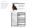
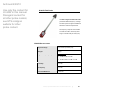
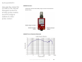
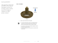
HI-4422 Field Probe
The ETS-Lindgren HI-4422
Field Probe is a fully intelligent sensor
enabling fast and accurate EMF
measurements with industry-leading
performance specifications. Optical
coupling to a variety of readout options
makes this probe ideally suited for a
wide range of field monitoring
applications. The HI-4422 is an
excellent tool for electric field
mapping, RADHAZ measurements,
and EMC field monitoring.
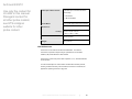
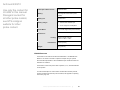
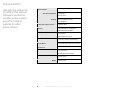
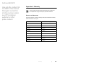
HI-4422 SPECIFICATIONS
Dynamic Range:
1.0–300 Volts per meter (V/m)
Ranges:
10, 30, 100, 300 V/m
Typical Frequency Response:
10 kHz–1.0 GHz ±1.0 dB
Linearity:
• ±0.5 dB full scale (F.S.)
• ±2 least significant bits (LSB) of
A/D converter
Isotropicity:
±0.5 dB
Overload Withstand:
1000 V/m maximum, all ranges
Battery-Operated Field Probes: HI-4422 Field Probe
|
63
Archived 6/29/10
Use only the content for
HI-4422 in this manual.
Disregard content for
all other probe models;
see ETS-Lindgren
website for other
probe content.
Environmental:
Operating Temperature
10°C to 40°C
50°F to 104°F
Humidity
5% to 95% relative humidity,
non-condensing
Fiber Optic Cable Connectors:
Standard FSMA
Battery:
3.6 VDC, 1400 mA-h rechargeable
Nickel-Cadmium (NiCd)
Battery Charger:
115/230 VAC
Approximately one hour
Probes:
64 mm (2.5 in) cube with probe
shields on three sides
Probe Mount:
1/4–20 UNC tapped hole (internal
thread) in base of probe
Weight:
64
|
0.4 kg (14 oz)
Battery-Operated Field Probes: HI-4422 Field Probe
Archived 6/29/10
Use only the content for
HI-4422 in this manual.
Disregard content for
all other probe models;
see ETS-Lindgren
website for other
probe content.
HI-4422 OPERATION
The HI-4422 is a battery-operated broadband radio frequency (RF) probe
designed for a variety of applications, including broadcast facilities, industrial
RF source and electromagnetic compliance (EMC) testing.
The HI-4422 measures field strength in each of three axes. It performs a vector
addition calculation on the readings and sends the result to the receiver through
a fiber optic cable. Data from each axis can be viewed individually, or can be
combined.
Limitations in system resolution may result in a non-zero reading when the
receiver is zeroed. If this occurs, it does not mean there is a problem with the
receiver, or that the readings are inaccurate. Probe linearity is specified as
+0.5 dB full scale. In addition, the variance of the A/D converter is +2 least
significant bits. When using the most sensitive range (10 V/m), these
specifications create the possibility that, under zero field conditions, the receiver
may display a non-zero value.
For a list and description of communication and information transfer protocols,
including command structure and probe commands, see Appendix E: Operating
Protocols on page 105.
Battery-Operated Field Probes: HI-4422 Field Probe
|
65
Archived 6/29/10
Use only the content for
HI-4422 in this manual.
Disregard content for
all other probe models;
see ETS-Lindgren
website for other
probe content.
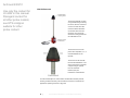
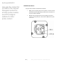
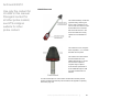
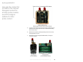
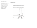
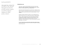
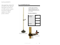
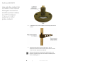
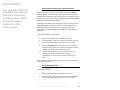
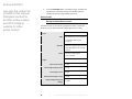
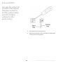
HI-4422 CONTROLS
A power switch, two fiber optic connectors, and a battery charger connector are
mounted on the HI-4422 housing.
CHARGER
Battery charger
connector
RCV
Power switch
Fiber optic
connectors (2)
ARM
OFF
XMIT
RCV/XMIT Fiber Optic Connectors
The fiber optic cable assembly from the receiver is attached to the HI-4422 by
two connectors. The cable ends are color-coded yellow for RCV and white
for XMIT. An identically colored dot is located on the probe housing next to each
of the connectors. Make sure that each cable is attached to the correct
connector.
When the cables are not attached, always cover the connectors with the
protective plastic covers supplied with the HI-4422, or with a similar material.
This prevents dirt and other contaminants from entering the connector, causing
communication problems.
66
|
Battery-Operated Field Probes: HI-4422 Field Probe
Archived 6/29/10
Use only the content for
HI-4422 in this manual.
Disregard content for
all other probe models;
see ETS-Lindgren
website for other
probe content.
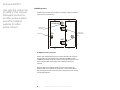
ARM/OFF Power Switch
The power switch activates and deactivates the HI-4422. In the ARM position,
the internal 3.6 VDC NiCd battery powers the probe. In the OFF position, the
probe is inactive. When not in use, turn the probe off to prolong battery life.
Battery Charger Connector
For complete information on the battery and battery charger for the HI-4422, see
Appendix D: Series H-491198-36 Battery Charger on page 99.
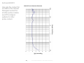
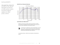
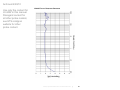
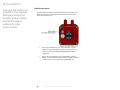
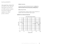
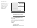
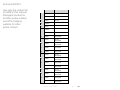
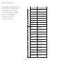
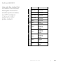
HI-4422 TYPICAL FREQUENCY RESPONSE
Battery-Operated Field Probes: HI-4422 Field Probe
|
67
Archived 6/29/10
Use only the content for
HI-4422 in this manual.
Disregard content for
all other probe models;
see ETS-Lindgren
website for other
probe content.
HI-4422 ADDITIONAL MAINTENANCE
Maintenance of the HI-4422 is limited to external components such as cables,
connectors, and probe shields. To replace the probe shields, see Probe Shield
Care and Replacement on page 79.
Any maintenance or calibration task requires probe disassembly,
which may void your warranty. Only ETS-Lindgren service personnel
should perform these tasks. To avoid problems with your warranty,
contact ETS-Lindgren Customer Service before performing any
maintenance.
For complete information on maintenance and calibration, see Maintenance on
page 23.
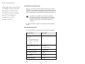
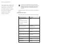
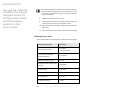
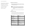
HI-4422 ADDITIONAL PARTS
The basic HI-4422 is shipped complete with a 10-meter fiber extension cable,
carrying case, battery charger, and connectors for extending the optic cable.
Use the following tables to order replacement or optional parts for the HI-4422.
Part Description
Part Number
Battery Charger
H-491198-36
(115/230 Volt)
Battery Pack, 3.6 VDC,
Rechargeable
H-491038
Carrying Case
H-491149
Element Cover Kit
H-651021
Cable, Fiber Optic, Glass
H-491106-xx
(xx=length in meters)
Fiber Optic/RS232 Interface
68
|
HI-4413P
Battery-Operated Field Probes: HI-4422 Field Probe
Archived 6/29/10
Use only the content for
HI-4422 in this manual.
Disregard content for
all other probe models;
see ETS-Lindgren
website for other
probe content.
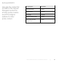
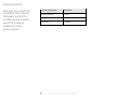
Part Description
Fiber Optic to USB Converter, USB
Interface
Part Number
HI-4413USB
Tripod, Dielectric, HI-4422
H-491009
Probe Stand
H-491269
HI-6100 Field Monitor
HI-6100
Graphical Readout
HI-4460
Numeric Readout
HI-4416
Battery-Operated Field Probes: HI-4422 Field Probe
|
69
Archived 6/29/10
Use only the content for
HI-4422 in this manual.
Disregard content for
all other probe models;
see ETS-Lindgren
website for other
probe content.
This page intentionally left blank.
70
|
Battery-Operated Field Probes: HI-4422 Field Probe
Archived 6/29/10
Use only the content for
HI-4422 in this manual.
Disregard content for
all other probe models;
see ETS-Lindgren
website for other
probe content.
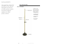
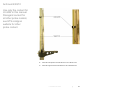
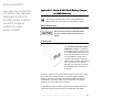
6.0 H-491269 Probe Stand
The ETS-Lindgren Probe Stand is
designed for EMC testing in anechoic
chambers and shielded enclosures. The
probe stand provides stable placement for
up to two probes.
PROBE STAND DIMENSIONS
Base Plate and
2438 mm
Tube Height:
96 in
Tube Height:
2248 mm
88.50 in
Base Width:
406 mm
16 in
Tube Width:
51 mm
2 in
H-491269 Probe Stand
|
71
Archived 6/29/10
Use only the content for
HI-4422 in this manual.
Disregard content for
all other probe models;
see ETS-Lindgren
website for other
probe content.
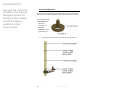
Probe Stand Assembly
PARTS TO ASSEMBLE
In addition to these
parts, the probe stand
includes the following
assembly hardware:
• Locking knobs (4)
• 1/4–20 x 3/4-inch
thumbscrews (2)
• 10–32 x 5/8-inch
set screw
• 8–32 x 3/8-inch
thumbscrew
72
|
H-491269 Probe Stand
Archived 6/29/10
Use only the content for
HI-4422 in this manual.
Disregard content for
all other probe models;
see ETS-Lindgren
website for other
probe content.
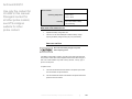
STEPS TO ASSEMBLE
1.
Insert the probe stand tube into the base plate.
• For accurate measurements, make sure to completely insert the
probe stand tube into the base plate. When fully inserted, the
bottom of the tube should rest evenly on the floor or surface.
• On the bottom of the base plate are rubber feet. Make sure all feet
rest evenly on the floor or surface.
• Incorrect tube placement or an uneven base can cause inaccurate
measurements.
H-491269 Probe Stand
|
73
Archived 6/29/10
Use only the content for
HI-4422 in this manual.
Disregard content for
all other probe models;
see ETS-Lindgren
website for other
probe content.
2.
To stabilize the tube, insert and tighten the two locking knobs into their
locations.
3.
Attach the probe carrier to the tube. Insert one 1/4–20 x 3/4
thumbscrew into the end closer to the tube, and a second one at the
center of the tube. Tighten the thumbscrews.
Testing can be performed using two probes simultaneously. If you
ordered an optional second probe carrier, attach the additional probe
carrier by repeating step 3.
74
|
H-491269 Probe Stand
Archived 6/29/10
Use only the content for
HI-4422 in this manual.
Disregard content for
all other probe models;
see ETS-Lindgren
website for other
probe content.
4.
Attach the scale pointer to the tube with the 10–32 x 5/8 set screw.
5.
Attach the support rod to the tube with the 8–32 x 3/8 thumbscrew.
H-491269 Probe Stand
|
75
Archived 6/29/10
Use only the content for
HI-4422 in this manual.
Disregard content for
all other probe models;
see ETS-Lindgren
website for other
probe content.
Probe Stand Operation
The support rod is marked with sensor positions that correspond to each probe,
and the probe stand tube is graduated to easily measure the distance to the floor.
The base plate includes:
• Handholds (2)—To
easily move
the probe stand
• Floor grid
finders (2)—To align
probe to floor grid
1.
76
Attach the probe to the probe carrier using the probe thumbscrew.
|
H-491269 Probe Stand
Archived 6/29/10
Use only the content for
HI-4422 in this manual.
Disregard content for
all other probe models;
see ETS-Lindgren
website for other
probe content.
2.
Align the scale pointer to the mark for the probe you are using, and
confirm the distance is between the estimated minimum and maximum
provided in the following Estimated Distance from Element to Floor
chart.
Field Probe
Minimum
Maximum
800 mm
2438 mm
(31.5 in)
(96 in)
HI-6053
673 mm
2438 mm
HI-4453
(26.5 in)
(96 in)
317.5 mm
2438 mm
(12.5 in)
(96 in)
HI-6022
292 mm
2438 mm
HI-6105
(11.5 in)
(96 in)
HI-4433
HI-6153
HI-4450
HI-4422
HI-6122
HI-6005
Estimated Distance from Element to Floor
H-491269 Probe Stand
|
77
Archived 6/29/10
Use only the content for
HI-4422 in this manual.
Disregard content for
all other probe models;
see ETS-Lindgren
website for other
probe content.
This page intentionally left blank.
78
|
H-491269 Probe Stand
Archived 6/29/10
Use only the content for
HI-4422 in this manual.
Disregard content for
all other probe models;
see ETS-Lindgren
website for other
probe content.
7.0 Probe Shield Care and Replacement
If you have an HI-6122, HI-6022, HI-6105, HI-6005, or HI-4422 Field Probe, over
time the probe shields (the cone-shaped structures with axis labels) may
accumulate foreign materials that could become embedded in the shield surface.
Probe shields must be kept clean to maintain proper operation.
If the probe shields need to be replaced, you may order them from
ETS-Lindgren. Follow these steps to replace the probe shields:
1.
Remove the nylon screws from the probe shield.
2.
Lift the shield straight up and away from the housing.
Lift the shield high enough to clear the internal antenna assembly, or
you may damage the assembly. Never touch the antenna assembly.
You may transfer a static charge to the assembly that may distort or
disable the measuring capability in that axis.
3.
With the probe in a protective, supportive position, carefully replace the
probe shield by lowering it straight down onto the housing.
Make sure to clear the internal antenna assembly when lowering the
shield or you may damage the assembly.
4.
Replace the screws snugly without over-tightening them.
Probe Shield Care and Replacement
|
79
Archived 6/29/10
Use only the content for
HI-4422 in this manual.
Disregard content for
all other probe models;
see ETS-Lindgren
website for other
probe content.
Over-tightening the screws may damage the screw heads. If you
require additional nylon screws, you may order them from
ETS-Lindgren or obtain them locally. Non-conductive screws must be
used for this application. Never use metal screws.
5.
80
Repeat this procedure for the other shields, if necessary.
|
Probe Shield Care and Replacement
Archived 6/29/10
Use only the content for
HI-4422 in this manual.
Disregard content for
all other probe models;
see ETS-Lindgren
website for other
probe content.
Appendix A: Warranty
See the Product Information Bulletin included with your shipment for
the complete ETS-Lindgren warranty for your EMC Field Probe.
DURATION OF WARRANTIES
All product warranties, except the warranty of title, and all remedies for warranty
failures are limited to three years.
Product Warranted
Duration of Warranty Period
FP5000
3 Years
FP6001
3 Years
HI-4422
3 Years
HI-6005
3 Years
HI-6022
3 Years
HI-6053
3 Years
HI-6105
3 Years
HI-6122
3 Years
HI-6153
3 Years
Warranty
|
81
Archived 6/29/10
Use only the content for
HI-4422 in this manual.
Disregard content for
all other probe models;
see ETS-Lindgren
website for other
probe content.
This page intentionally left blank.
82
|
Warranty
Archived 6/29/10
Use only the content for
HI-4422 in this manual.
Disregard content for
all other probe models;
see ETS-Lindgren
website for other
probe content.
Appendix B: Series H-491198-01 Battery Charger
for NiMH Batteries
The HI-6053 Field Probe contains four AAA Nickel-Metal Hydride
(NiMH) batteries, and uses the Series H-491198-01 Battery Charger.
SAFETY PRECAUTIONS
Before operating the Series H-491198-01 Battery
Charger, see General Safety Considerations on
page ix.
INTRODUCTION
The H-491198-01 Nickel-Metal
Hydride (NiMH) Battery Charger is
a dual power source battery charger.
It charges 4.8 volt 220 mA NiMH
batteries and is powered by
85-264 VAC line power or 12.5 VDC.
The H-491198-01 Battery Charger
uses a -(dV)/(dT) negative delta V
technique to determine when the
battery is fully charged, which is
typically two hours. With this
technique, the charge state of the
battery has no effect other than
shortening the charge time.
Housed in a rugged enclosure, power enters the battery charger through a power
entry module, which contains the fuses, or an optional cigarette lighter plug
adapter. The front face of the battery charger displays LEDs that provide the
operating status. The battery charger connects to the device being charged
through a short cord terminated with a power jack.
Series H-491198-01 Battery Charger for NiMH Batteries
|
83
Archived 6/29/10
Use only the content for
HI-4422 in this manual.
Disregard content for
all other probe models;
see ETS-Lindgren
website for other
probe content.
An integrated circuit within the battery charger monitors the battery voltage and
controls the charging functions according to the charge state of the battery.
BATTERY LIFE
The NiMH batteries powering the battery-operated probe have high energy
density for maximum operating time between charges, but also have a significant
self-discharge characteristic. When the probe is stored for longer than a week or
two, the batteries will discharge even though not in use. Leaving the batteries in
a discharged condition for long periods of time may result in reduced battery life.
For optimum testing time, charge the batteries before use.
The battery charger is microprocessor controlled to charge the batteries in the
fastest possible manner. When the charger senses that the batteries are fully
charged, the charging current drops to a maintenance level. This level is
sufficient to maintain the full charged without causing battery damage. It is
acceptable to leave the probe connected to the battery charger for extended
periods of time.
With proper care, the batteries should last two to three years. Follow these
recommendations to ensure maximum battery life and optimum testing
performance:
•
Turn the probe off when the probe is not in use. Leaving the probe on
for extended periods of time will damage the batteries. When the
batteries are discharged, the flashing power ON indicator will not
function.
•
When possible, leave the robe connected to the battery charger, and
the battery charger connected to the mains electrical supply (charger
operating). The battery charger status indicators will show CHARGER
ON and COMPLETE when the batteries are on a maintenance charge.
•
Operate the robe only within the optimum operating temperature range
of +20ºC to +30ºC (+68ºF to +86ºF). Although NiMH batteries are
rated for operation in temperatures from -20ºC to +65ºC
(-4ºF to +140ºF), operating the probe at temperature extremes
reduces the operating time of the batteries.
•
Make sure the batteries are fully charged before resuming operation.
The batteries do not require periodic deep discharges to reverse the
effect caused by repeated shallow discharges, but undercharging can
reduce battery capacity.
84
|
Series H-491198-01 Battery Charger for NiMH Batteries
Archived 6/29/10
Use only the content for
HI-4422 in this manual.
Disregard content for
all other probe models;
see ETS-Lindgren
website for other
probe content.
Fully charged batteries (nominal output voltage of 4.8 VDC) provide up to
30 hours of operation. When the batteries have discharged to 4.4 VDC, the probe
will operate, but the batteries need to be charged. When the voltage drops below
4.0 VDC, measurement accuracy may be compromised by continued operation.
When the battery voltage indication is less than 4 volts, a low battery indication is
attached to the output data string warning of the problem. ETS-Lindgren software
applications provide a warning indication on the display screen of the readout
device. It is recommended that custom software packages using data from the
probe monitor the data output for this condition.
If the batteries exhibit low terminal voltages during charging, or if they appear
unable to acquire or maintain a charge, the batteries may be shorted or
damaged. To replace the batteries, see HI-6053 Battery Replacement on
page 54.
CHARGING THE BATTERIES
For maximum battery life, fully charge the batteries before placing the probe into
service. Failing to fully charge the batteries may result in reduced battery life and
cause premature battery failure.
To charge a battery:
1.
Make sure the probe is off or the batteries will not charge.
2.
Connect the battery charger to the electrical mains, and then plug the
charger output into the battery charger connector on the probe.
Never attempt to recharge a non-rechargeable
battery.
CHARGING INDICATORS
The following LEDs are located on the front of the battery charger:
•
POWER ON (green)—Indicates the battery charger is connected to the
AC power source.
•
NO BATTERY (amber)—Indicates the battery charger does not detect
a battery.
Series H-491198-01 Battery Charger for NiMH Batteries
|
85
Archived 6/29/10
•
Use only the content for
HI-4422 in this manual.
Disregard content for
all other probe models;
see ETS-Lindgren
website for other
probe content.
PENDING (amber)—Indicates the battery charger detects a battery.
Before fast charging can begin, the battery voltage must fall within
predetermined acceptable limits. A pulse-trickle charge is provided to
bring a depleted battery to a valid charge prior to fast charge.
•
CHARGING (amber)—Indicates the voltage pre-qualification condition
has been met, and fast charge has started.
Fast charging continues until termination by a peak voltage detect or a
maximum charge time. For peak voltage detect, the fast charge is
terminated when the battery voltage is lower than the previously
measured values by 24mV. If a peak voltage is not detected, then the
fast charge is terminated when the maximum time limit of 180 minutes
is reached.
•
COMPLETE (green)—Indicates a fast charging peak voltage is
detected.
If the probe is turned on during the fast charge period of the charge
cycle, the current surge that the batteries provide to the electronics in
the probe will cause a momentary voltage drop on the batteries,
causing the charger to terminate the fast charge based on a peak
voltage detect condition.
The battery charger switches to top-off charge mode that provides a charge
current one-eighth of the fast charge rate. This charge continues from the time
when a peak voltage detect terminates the fast charge, until the maximum time of
180 minutes is reached. If the probe is disconnected from the charger at this
point in the charge cycle, the batteries will operate properly.
Following the maximum time of 180 minutes, a pulse-trickle charge mode is used
to compensate for the self-discharge of the batteries while idle in the charger.
The fast charge current is low enough that there is not always enough heating of
the battery cells to cause the voltage to drop. With no voltage drop there is no
peak voltage detection, and the fast charge will terminate after the maximum time
of 180 minutes is reached.
86
|
Series H-491198-01 Battery Charger for NiMH Batteries
Archived 6/29/10
Use only the content for
HI-4422 in this manual.
Disregard content for
all other probe models;
see ETS-Lindgren
website for other
probe content.
SYNCHRONIZING THE BATTERY CHARGE INDICATOR
The probe has internal circuitry to track the charge condition of the batteries.
NiMH batteries have a sharp discharge-curve knee, which means there is little
indication that the batteries are nearly discharged prior to a low battery condition.
The internal circuitry tracks the charging and discharging currents of the batteries
and displays the calculated battery condition.
It is possible that the battery charge indication may lose synchronization with the
actual battery condition. A loss of synchronization may be indicated by a low
battery charge alert after the batteries were recently fully charged. Loss of
synchronization may also be indicated by short battery life and premature low
battery alert.
To synchronize the battery charge indicator:
1.
Make sure the probe is off or the batteries will not charge.
2.
Connect the battery charger to the electrical mains, and then plug the
charger output into the battery charger connector on the probe.
3.
Press the DISCHARGE button on the battery charger. The batteries
will fully discharge, and then fully recharge. The total time required to
discharge and recharge is approximately seven hours.
4.
For best results, repeat the process once. However, it may be
necessary to repeat the process three times for proper
synchronization. The synchronization process may take up to 12
hours.
When completely charged, the battery indicator for the probe should indicate a
charge level of more than 90%.
DISCHARGING A BATTERY
To discharge the batteries:
1.
Make sure the probe is off or the batteries will not charge.
2.
Connect the battery charger to the electrical mains, and then plug the
charger output into the battery charger connector on the probe.
Series H-491198-01 Battery Charger for NiMH Batteries
|
87
Archived 6/29/10
Use only the content for
HI-4422 in this manual.
Disregard content for
all other probe models;
see ETS-Lindgren
website for other
probe content.
3.
Press the DISCHARGE button on the battery charger. The batteries
will fully discharge, and then fully recharge. The total time required to
discharge and recharge is approximately seven hours.
SPECIFICATIONS
BATTERY CHARGER SPECIFICATIONS
The battery charger may be powered by standard line voltage (110–240 VAC,
50–60 Hz) or by an optional automobile cigarette lighter plug (12.5 VDC).
Power
Main:
IEC filtered AC power input module
110-240 VAC, 500 mA max,
50-100 Hz
Alternate:
Automobile cigarette lighter to 2 mm
power plug adapter cord, 12.5 Vdc,
100 mA
Fuses:
250 volt, 1.0 Amp, Type T
(5 mm x 20 mm)
Output
Open Circuit Voltage:
12 Vdc
Fast Charge Pending Current:
2.0 mA
Fast Charge Current:
220 mA
Pulsed Trickle Charge Current:
2.0 mA
Output Voltage (During Fast
Charge):
88
|
4–8 Vdc
Series H-491198-01 Battery Charger for NiMH Batteries
Archived 6/29/10
Use only the content for
HI-4422 in this manual.
Disregard content for
all other probe models;
see ETS-Lindgren
website for other
probe content.
NiMH Battery:
• 4 AAA batteries, rechargeable
NiMH, 600 mAH (rapid charge
cells, 1.2 volts/cell)
• ETS-Lindgren Part #400038
(quantity required = 4)
Environmental
Operating Temperature:
10°C to 40°C
50°F to 104°F
Humidity:
5% to 95% relative humidity,
non-condensing
MAINTENANCE RECOMMENDATIONS
•
•
Operate the battery charger with care.
There are no user serviceable parts inside the battery charger.
Opening the battery charger housing may void your warranty.
REPLACING THE FUSE
Disconnect the battery charger from power
before replacing a fuse.
If the battery charger fails to operate, check for a blown fuse inside the power
entry module. A blown fuse must be replaced with the same value and type of
fuse, or an unsafe condition may result. Use only 250 Volt, 1.0 Amp, Type T
(5 mm x 20 mm) fuses.
To replace a fuse:
1.
Two fuses are located in the fuse drawer in the power input module.
Use a screwdriver to open the drawer.
2.
The fuse towards the outside of the drawer is the spare. Remove the
spare fuse from the module.
Series H-491198-01 Battery Charger for NiMH Batteries
|
89
Archived 6/29/10
Use only the content for
HI-4422 in this manual.
Disregard content for
all other probe models;
see ETS-Lindgren
website for other
probe content.
3.
Replace the blown fuse with the spare fuse.
4.
Slide the fuse drawer back into the module. Make sure that the drawer
snaps securely into its locked position.
90
|
Series H-491198-01 Battery Charger for NiMH Batteries
Archived 6/29/10
Use only the content for
HI-4422 in this manual.
Disregard content for
all other probe models;
see ETS-Lindgren
website for other
probe content.
Appendix C: Series H-491198-48 Battery Charger
for NiMH Batteries
The HI-6022 and HI-6005 probes contain a Nickel-Metal Hydride
(NiMH) battery, and use the Series H-491198-48 Battery Charger.
SAFETY PRECAUTIONS
Before operating the Series H-491198-48 Battery
Charger, see General Safety Considerations on
page ix.
INTRODUCTION
The H-491198-48 Nickel-Metal Hydride
(NiMH) Battery Charger is a dual power
source battery charger. It charges 4.8 volt
25 mA NiMH batteries and is powered by
85-264 VAC line power or 12.5 VDC. The
H-491198-48 Battery Charger uses a
-(dV)/(dT) negative delta V technique to
determine when the battery is fully charged,
which is typically two hours. With this
technique, the charge state of the battery
has no effect other than shortening the
charge time.
Housed in a rugged enclosure, power enters the battery charger through a power
entry module, which contains the fuses, or an optional cigarette lighter plug
adapter. The front face of the battery charger displays LEDs that provide the
operating status. The battery charger connects to the device being charged
through a short cord terminated with a power jack.
An integrated circuit within the battery charger monitors the battery voltage and
controls the charging functions according to the charge state of the battery.
Series H-491198-48 Battery Charger for NiMH Batteries
|
91
Archived 6/29/10
Use only the content for
HI-4422 in this manual.
Disregard content for
all other probe models;
see ETS-Lindgren
website for other
probe content.
BATTERY LIFE
The NiMH battery powering the battery-operated probe has high energy density
for maximum operating time between charges, but also has a significant selfdischarge characteristic. When the probe is stored for longer than a week or two,
the battery will discharge even though not in use. Leaving the battery in a
discharged condition for long periods of time may result in reduced battery life.
For optimum testing time, charge the battery before use.
The battery charger is microprocessor controlled to charge the battery in the
fastest possible manner. When the charger senses that the battery is fully
charged, the charging current drops to a maintenance level. This level is
sufficient to maintain the battery fully charged without causing battery damage. It
is acceptable to leave the probe connected to the battery charger for extended
periods of time.
With proper care, the battery should last two to three years. Follow these
recommendations to ensure maximum battery life and optimum testing
performance:
•
Set the power switch on the probe to the OFF position when the probe
is not in use. Leaving the power switch in the ON position for extended
periods of time will damage the battery. When the battery is
discharged, the flashing power ON indicator will not function.
•
When possible, leave the probe connected to the battery charger, and
the battery charger connected to the mains electrical supply (charger
operating). The battery charger status indicators will show CHARGER
ON and COMPLETE when the battery is on a maintenance charge.
•
Operate the probe only within the optimum operating temperature
range of +20ºC to +30ºC (+68ºF to +86ºF). Although NiMH batteries
are rated for operation in temperatures from -20ºC to +65ºC
(-4ºF to +140ºF), operating the probe at temperature extremes
reduces the operating time of the batteries.
•
Make sure the battery is fully charged before resuming operation. The
battery does not require periodic deep discharges to reverse the effect
caused by repeated shallow discharges, but undercharging can reduce
battery capacity.
92
|
Series H-491198-48 Battery Charger for NiMH Batteries
Archived 6/29/10
Use only the content for
HI-4422 in this manual.
Disregard content for
all other probe models;
see ETS-Lindgren
website for other
probe content.
A fully charged battery (nominal output voltage of 4.8 VDC) provides up to
10 hours of operation. When the battery has discharged to 4.4 VDC, the probe
will operate, but the battery will need to be charged. When the voltage drops
below 4.0 VDC, measurement accuracy may be compromised by continued
operation. When the battery voltage indication is less than four volts, a low
battery indication is attached to the output data string warning of the problem.
ETS-Lindgren software applications provide a warning indication on the display
screen of the readout device. It is recommended that custom software packages
using data from the probe monitor the data output for this condition.
If the battery exhibits low terminal voltages during charging, or if it appears
unable to acquire or maintain a charge, individual cells in the battery may be
shorted or damaged. If your battery needs replacement for any reason, contact
ETS-Lindgren Customer Service.
CHARGING A BATTERY
For maximum battery life, fully charge the battery for the probe before placing the
probe into service. Failing to fully charge the battery may result in reduced
battery life and cause premature battery failure.
To charge a battery:
1.
Make sure the power switch on the probe is set to the OFF position or
the battery will not charge.
2.
Connect the battery charger to the electrical mains, and then connect
the charger output to the charger jack on the probe.
Never attempt to recharge a non-rechargeable
battery.
CHARGING INDICATORS
The following LEDs are located on the front of the battery charger:
•
POWER ON (green)—Indicates the battery charger is connected to the
AC power source.
•
NO BATTERY (amber)—Indicates the battery charger does not detect
a battery.
Series H-491198-48 Battery Charger for NiMH Batteries
|
93
Archived 6/29/10
•
Use only the content for
HI-4422 in this manual.
Disregard content for
all other probe models;
see ETS-Lindgren
website for other
probe content.
PENDING (amber)—Indicates the battery charger detects a battery.
Before fast charging can begin, the battery voltage must fall within
predetermined acceptable limits. A pulse-trickle charge is provided to
bring a depleted battery to a valid charge prior to fast charge.
•
CHARGING (amber)—Indicates the voltage pre-qualification condition
has been met, and fast charge has started.
Fast charging continues until termination by a peak voltage detect or a
maximum charge time. For peak voltage detect, the fast charge is
terminated when the battery voltage is lower than the previously
measured values by 24mV. If a peak voltage is not detected, then the
fast charge is terminated when the maximum time limit of 180 minutes
is reached.
•
COMPLETE (green)—Indicates a fast charging peak voltage is
detected.
If the probe is turned on during the fast charge period of the charge
cycle, the current surge that the battery provides to the electronics in
the probe will cause a momentary voltage drop on the battery, causing
the charger to terminate the fast charge based on a peak voltage
detect condition.
The battery charger switches to top-off charge mode that provides a charge
current one-eighth of the fast charge rate. This charge continues from the time
when a peak voltage detect terminates the fast charge, until the maximum time of
180 minutes is reached. If the probe is disconnected from the charger at this
point in the charge cycle, the battery will operate properly.
Following the maximum time of 180 minutes, a pulse-trickle charge mode is used
to compensate for the self-discharge of the battery while idle in the charger.
The batteries are small, and the fast charge current is low. The fast charge
current is low enough that there is not always enough heating of the battery cells
to cause the voltage to drop. With no voltage drop there is no peak voltage
detection, and the fast charge will terminate after the maximum time of 180
minutes is reached.
94
|
Series H-491198-48 Battery Charger for NiMH Batteries
Archived 6/29/10
Use only the content for
HI-4422 in this manual.
Disregard content for
all other probe models;
see ETS-Lindgren
website for other
probe content.
SYNCHRONIZING THE BATTERY CHARGE INDICATOR
The probe has internal circuitry to track the charge condition of the battery. NiMH
batteries have a sharp discharge-curve knee, which means there is little
indication that the battery is nearly discharged prior to a low battery condition.
The internal circuitry tracks the charging and discharging currents of the battery
and displays the calculated battery condition.
It is possible that the battery charge indication may lose synchronization with the
actual battery condition. A loss of synchronization may be indicated by a low
battery charge alert after the battery was recently fully charged. Loss of
synchronization may also be indicated by short battery life and premature low
battery alert.
To synchronize the battery charge indicator:
1.
Make sure the power switch on the probe is set to the OFF position or
the battery will not charge.
2.
Connect the battery charger to the electrical mains, and then connect
the charger output to the charger jack on the probe.
3.
Press the DISCHARGE button on the battery charger. The battery will
fully discharge, and then fully recharge. The total time required to
discharge and recharge is approximately seven hours.
4.
For best results, repeat the process once. However, it may be
necessary to repeat the process three times for proper
synchronization. The synchronization process may take up to
12 hours.
When completely charged, the battery indicator for the probe should indicate a
charge level of more than 90%.
DISCHARGING A BATTERY
To discharge a battery:
1.
Make sure the power switch on the probe is set to the OFF position or
the battery will not charge.
2.
Connect the battery charger to the electrical mains, and then connect
the charger output to the charger jack on the probe.
Series H-491198-48 Battery Charger for NiMH Batteries
|
95
Archived 6/29/10
Use only the content for
HI-4422 in this manual.
Disregard content for
all other probe models;
see ETS-Lindgren
website for other
probe content.
3.
Press the DISCHARGE button on the battery charger. The battery will
fully discharge, and then fully recharge. The total time required to
discharge and recharge is approximately seven hours.
SPECIFICATIONS
BATTERY CHARGER SPECIFICATIONS
The battery charger may be powered by standard line voltage (110–240 VAC,
50–60 Hz) or by an optional automobile cigarette lighter plug (12.5 VDC).
Power
Main:
IEC filtered AC power input module
110-240 VAC, 500 mA max,
50-100 Hz
Alternate:
Automobile cigarette lighter to 2 mm
power plug adapter cord, 12.5 Vdc,
100 mA
Fuses:
250 volt, 1.0 Amp, Type T
(5 mm x 20 mm)
Output
Open Circuit Voltage:
12 Vdc
Fast Charge Pending Current:
2.0 mA
Fast Charge Current:
25 mA
Pulsed Trickle Charge Current:
2.0 mA
Output Voltage (During Fast
Charge):
96
|
4–8 Vdc
Series H-491198-48 Battery Charger for NiMH Batteries
Archived 6/29/10
Use only the content for
HI-4422 in this manual.
Disregard content for
all other probe models;
see ETS-Lindgren
website for other
probe content.
NiMH Battery:
• 4.8 volt 4 cell NiMH Battery,
25 mAH (rapid charge cells,
1.2 volts/cell)
• ETS-Lindgren Part #H-491193
Environmental
Operating Temperature:
10°C to 40°C
50°F to 104°F
Humidity:
5% to 95% relative humidity,
non-condensing
MAINTENANCE RECOMMENDATIONS
•
•
Operate the battery charger with care.
There are no user serviceable parts inside the battery charger.
Opening the battery charger housing may void your warranty.
REPLACING THE FUSE
Disconnect the battery charger from power
before replacing a fuse.
If the battery charger fails to operate, check for a blown fuse inside the power
entry module. A blown fuse must be replaced with the same value and type of
fuse, or an unsafe condition may result. Use only 250 Volt, 1.0 Amp, Type T
(5 mm x 20 mm) fuses.
To replace a fuse:
1.
Two fuses are located in the fuse drawer in the power input module.
Use a screwdriver to open the drawer.
2.
The fuse towards the outside of the drawer is the spare. Remove the
spare fuse from the module.
Series H-491198-48 Battery Charger for NiMH Batteries
|
97
Archived 6/29/10
Use only the content for
HI-4422 in this manual.
Disregard content for
all other probe models;
see ETS-Lindgren
website for other
probe content.
3.
Replace the blown fuse with the spare fuse.
4.
Slide the fuse drawer back into the module. Make sure that the drawer
snaps securely into its locked position.
98
|
Series H-491198-48 Battery Charger for NiMH Batteries
Archived 6/29/10
Use only the content for
HI-4422 in this manual.
Disregard content for
all other probe models;
see ETS-Lindgren
website for other
probe content.
Appendix D: Series H-491198-36 Battery Charger
for NiCd Batteries
The HI-4422 Field Probe contains a Nickel-Cadmium (NiCd) battery,
and uses the Series H-491198-36 Battery Charger.
SAFETY PRECAUTIONS
Before operating the Series H-491198-36 Battery
Charger, see General Safety Considerations on
page ix.
INTRODUCTION
The H-491198-48 Nickel-Cadmium (NiCd)
Battery Charger is a dual power source
battery charger. It charges 3.6 volt
1400 mAH NiCd batteries and is powered
by 120-240 VAC line power or 12.5 VDC.
The H-491198-36 Battery Charger uses a
-(dV)/(dT) negative delta V technique to
determine when the battery is fully charged,
which is typically one hour. With this
technique, the charge state of the battery
has no effect other than shortening the
charge time.
Housed in a rugged enclosure, power enters the battery charger through a power
entry module, which contains the fuses, or an optional cigarette lighter plug
adapter. The front face of the battery charger displays LEDs that provide the
operating status. The battery charger connects to the device being charged
through a short cord terminated with a power jack.
An integrated circuit within the battery charger monitors the battery voltage and
controls the charging functions according to the charge state of the battery.
Series H-491198-36 Battery Charger for NiCd Batteries
|
99
Archived 6/29/10
Use only the content for
HI-4422 in this manual.
Disregard content for
all other probe models;
see ETS-Lindgren
website for other
probe content.
BATTERY LIFE
A fully-charged battery (nominal output voltage of 3.6 VDC) provides up to 40
hours of operation. When the battery has discharged to 3.3 VDC, the probe is still
operational, but the battery needs charging. When the voltage drops below
3.18 VDC, measurement accuracy will be compromised by further operation.
Follow these recommendations to ensure maximum battery life and optimum
testing performance:
•
Operate the probe only within the optimum operating temperature
range of +20°C to +30°C (+68°F to +86°F). Although NiCd batteries
are rated for operation in temperatures from -20°C to +65°C
(-4°F to +140°F), operating the probe at temperature extremes
reduces the operating time of the batteries.
•
Make sure the battery is fully charged before resuming operation. The
battery does not require periodic deep discharges to reverse the effect
caused by repeated shallow discharges, but undercharging can reduce
battery capacity.
If the battery exhibits low terminal voltages during charging, or if it appears
unable to acquire or maintain a charge, individual cells in the battery may be
shorted or damaged. If your battery needs replacement for any reason, contact
ETS-Lindgren Customer Service.
CHARGING A BATTERY
1.
Make sure the power switch on the probe is set to the OFF position or
the battery will not charge.
2.
Connect the battery charger to the proper power source, and then
connect the charger to the charger jack on the probe.
Charging takes approximately one hour, depending on the degree of
battery discharge. When charging is complete, the battery charger
automatically enters into a trickle charge, and continues until the probe
is disconnected.
Never attempt to recharge a non-rechargeable
battery.
100
|
Series H-491198-36 Battery Charger for NiCd Batteries
Archived 6/29/10
Use only the content for
HI-4422 in this manual.
Disregard content for
all other probe models;
see ETS-Lindgren
website for other
probe content.
CHARGING INDICATORS
The following LEDs are located on the front of the battery charger:
•
POWER ON (green)—Indicates the battery charger is connected to the
AC power source.
•
NO BATTERY (amber)—Indicates the battery charger does not detect
a battery.
•
PENDING (amber)—Indicates the battery charger detects a battery.
Before fast charging can begin, the battery voltage must fall within
predetermined acceptable limits. A pulse-trickle charge is provided to
bring a depleted battery to a valid charge prior to fast charge.
•
CHARGING (amber)—Indicates the voltage pre-qualification condition
has been met, and fast charge has started.
•
COMPLETE (green)—Indicates a fast charging peak voltage is
detected. The probe can remain connected to the battery charger
indefinitely while in this maintenance mode.
Series H-491198-36 Battery Charger for NiCd Batteries
|
101
Archived 6/29/10
Use only the content for
HI-4422 in this manual.
Disregard content for
all other probe models;
see ETS-Lindgren
website for other
probe content.
SPECIFICATIONS
BATTERY CHARGER SPECIFICATIONS
The H-491198-36 charger may be powered by standard line voltage (110–
240 Vac, 50–60 Hz) or by an optional automobile cigarette lighter plug
(12.5 Vdc).
Power
Main:
IEC filtered AC power input module
110-240 VAC, 500 mA max,
50-100 Hz
Alternate:
Automobile cigarette lighter to 2 mm
power plug adapter cord, 12.5 Vdc,
100 mA
Fuses:
250 volt, 1.0 Amp, Type T
(5 mm x 20 mm)
Output
Open Circuit Voltage:
15 Vdc
Fast Charge Pending Current:
60 mA
Fast Charge Current:
Pulsed Trickle Charge Current:
Output Voltage (During Fast
Charge):
NiMH Battery:
1400 mA
50 mA
3–6 Vdc
• 3.6 volt 3 cell NiCd Battery,
1400 mAH (rapid charge cells,
1.2 volts/cell)
• ETS-Lindgren Part #491038
102
|
Series H-491198-36 Battery Charger for NiCd Batteries
Archived 6/29/10
Use only the content for
HI-4422 in this manual.
Disregard content for
all other probe models;
see ETS-Lindgren
website for other
probe content.
Environmental
Operating Temperature:
10°C to 40°C
50°F to 104°F
Humidity:
5% to 95% relative humidity,
non-condensing
MAINTENANCE RECOMMENDATIONS
•
•
Operate the battery charger with care.
There are no user serviceable parts inside the battery charger.
Opening the battery charger housing may void your warranty.
REPLACING THE FUSE
Disconnect the battery charger from power
before replacing a fuse.
If the battery charger fails to operate, check for a blown fuse inside the power
entry module. A blown fuse must be replaced with the same value and type of
fuse, or an unsafe condition may result. Use only 250 Volt, 1.0 Amp, Type T
(5 mm x 20 mm) fuses.
To replace a fuse:
1.
Two fuses are located in the fuse drawer in the power input module.
Use a screwdriver to open the drawer.
2.
The fuse towards the outside of the drawer is the spare. Remove the
spare fuse from the module.
Series H-491198-36 Battery Charger for NiCd Batteries
|
103
Archived 6/29/10
Use only the content for
HI-4422 in this manual.
Disregard content for
all other probe models;
see ETS-Lindgren
website for other
probe content.
3.
Replace the blown fuse with the spare fuse.
4.
Slide the fuse drawer back into the module. Make sure that the drawer
snaps securely into its locked position.
104
|
Series H-491198-36 Battery Charger for NiCd Batteries
Archived 6/29/10
Use only the content for
HI-4422 in this manual.
Disregard content for
all other probe models;
see ETS-Lindgren
website for other
probe content.
Appendix E: Operating Protocols
The information in this section is subject to change, and is included for
reference only. ETS-Lindgren recommends that you use the
commands and information provided in ETSProbe DLL User Guide on
page 117.
The following information assumes that the HI-6113 Laser Data Interface (LDI),
HI-4413P Fiber Optic Modem, or HI-4413USB Fiber Optic to USB Converter was
purchased and is communicating directly with the probe.
COMMUNICATION PROTOCOL
HI-61XX SERIES LASERPRO FIELD PROBES
Data Type:
RS-232 Serial
Data Mode:
Asynchronous
Word Length:
8 bit
Parity:
N
Stop Bits:
1
Data Rate:
115,200 baud
HI-60XX SERIES BATTERY-OPERATED FIELD PROBES
Data Type:
RS-232 Serial
Data Mode:
Asynchronous
Word Length:
7bit
Parity:
Odd
Stop Bits:
1
Data Rate:
9600 baud
Operating Protocols
|
105
Archived 6/29/10
Use only the content for
HI-4422 in this manual.
Disregard content for
all other probe models;
see ETS-Lindgren
website for other
probe content.
HI-4422 FIELD PROBE
Data Type:
RS-232 Serial
Data Mode:
Asynchronous
Word Length:
7 bit
Parity:
Odd
Stop Bits:
1
Data Rate:
9600 baud
INFORMATION TRANSFER PROTOCOL
The probe responds to commands from another device; it transmits no data
without first receiving instructions to do so.
COMMAND STRUCTURE
See the following pages for detailed information regarding the command
structure to the probe. When the probe completes the command, it responds with
a string consisting of:
•
A start character (":")
•
The command letter
•
Data (if required)
•
<CR> (a carriage return)
If the command does not require the probe to return any data, the probe simply
responds with the start character (":") then the command letter and a carriage
return. If an error occurs, the probe responds with an error code.
PROBE COMMANDS
All probe commands return :E7 when the probe is turned off.
106
|
Operating Protocols
Archived 6/29/10
Use only the content for
HI-4422 in this manual.
Disregard content for
all other probe models;
see ETS-Lindgren
website for other
probe content.
HI-61XX SERIES LASERPRO FIELD PROBES
Probe
Description
Probe Response
Command
B<CR>
Read probe converter
:Bxx.xx<CR>
voltage
BP
Read probe converter
voltage in hexadecimal
format
:B64N
• N=safe operating level
• F=fail level
Voltage reported as 0–64;
64 corresponds to 100%
The BP command is provided for backward compatibility and should
not be used to monitor the converter voltage, which always responds
with :B64N<CR>.
Probe
Command
D3
Description
Probe Response
Read probe data
:Dx.xxxyy.yyzzz.zB<CR>
• xxxx, yyyy, zzzz=
4-digit axis values with
floating decimal point
• B=battery flag, N or F
D5
Read probe data
:Dx.xxxyy.yyzzz.zcccc.B<CR>
• xxxx, yyyy, zzzz=
4-digit axis values with
floating decimal point
• cccc=composite field value
with floating decimal point
• B=battery flag, N or F
Operating Protocols
|
107
Archived 6/29/10
Use only the content for
HI-4422 in this manual.
Disregard content for
all other probe models;
see ETS-Lindgren
website for other
probe content.
Probe
Description
Probe Response
Command
I
Identification command
:I61XX<sr><sn><cd>B<CR>
• XX=specific probe model
• sr=10-character software
revision
• sn=8-character serial
number
• cd=8-character calibration
date
• B=battery flag, N or F
The Identification command, I, may also be used as the first command
sent. The command will turn on the laser. Once communication
between the probe and the Laser Data Interface (LDI) is established,
the return string will be sent. Subsequent I commands immediately
send the return string.
Probe
Command
TC
Description
Probe Response
Read temperature in
:Txxxx.<CR>
Centigrade
TF
Read temperature in
:Txxxx.<CR>
Fahrenheit
<Null><CR>
Send the ASCII null
:N<CR>
character
<Null><CR> is a special command that can be used as the initial
command to the probe after it is turned on.
108
|
Operating Protocols
Archived 6/29/10
Use only the content for
HI-4422 in this manual.
Disregard content for
all other probe models;
see ETS-Lindgren
website for other
probe content.
HI-6053 AND HI-6005 FIELD PROBES
Probe
Description
Probe Response
Command
B<CR>
Read battery voltage
:Bxx.xx<CR>
• :B04.80
=100% of charge
=4.8 volts
• :B04.00
=0% of charge
=4.0 volts
BP
Read battery capacity in
Bxx<N or F><CR>
percentage
• :B64N
=100% of charge
=4.8 volts
• :B00F
=0% of charge
=4.0 volts
• N=safe operating level
• F=fail level
Percentage reported in
hexadecimal, 0% to 64%
The BP command is provided for backward compatibility and should
not be used to monitor the converter voltage, which always responds
with :B64N<CR>.
Operating Protocols
|
109
Archived 6/29/10
Use only the content for
HI-4422 in this manual.
Disregard content for
all other probe models;
see ETS-Lindgren
website for other
probe content.
Probe
Description
Probe Response
Command
D3
Read probe data
:Dx.xxxyy.yyzzz.zB<CR>
• xxxx, yyyy, zzzz=
4-digit axis values with
floating decimal point
• B=battery flag, N or F
D5
Read probe data
:Dx.xxxyy.yyzzz.zcccc.B<CR>
• xxxx, yyyy, zzzz=
4-digit axis values with
floating decimal point
• cccc=composite field value
with floating decimal point
• B=battery flag, N or F
I
Identification command
:I60XX<sr><sn><cd>B<CR>
• XX=specific probe model
• sr=10-character software
revision
• sn=8-character serial
number
• cd=8-character calibration
date
• B=battery flag, N or F
The Identification command, I, may also be used as the first command
sent. The command will turn on the laser. Once communication
between the probe and the Laser Data Interface (LDI) is established,
the return string will be sent. Subsequent I commands immediately
send the return string.
TC
Read temperature in
:Txxxx.<CR>
Centigrade
110
|
Operating Protocols
Archived 6/29/10
Use only the content for
HI-4422 in this manual.
Disregard content for
all other probe models;
see ETS-Lindgren
website for other
probe content.
Probe
Description
Probe Response
Command
TF
Read temperature in
:Txxxx.<CR>
Fahrenheit
<Null><CR>
Send the ASCII null
:N<CR>
character
<Null><CR> is a special command that can be used as the initial
command to the probe after it is turned on.
HI-4422 FIELD PROBE
When remotely operating the probe with commands manually entered from a
computer keyboard, the HI-4422 may sleep between commands, especially if the
sleep timer is set to a one or two second interval. The HI-4422 may appear
unresponsive to commands, or may appear to skip commands. If this occurs,
send an S0 command, and keep sending the command as fast as possible until
the probe responds with :S, and the sleep timer is turned off. Then the probe will
provide the proper responses.
Probe
Command
Axxx
Description
Probe Response
Axis enable/disable.
• x=E (enable) or D
(disable)
• xxx order=X axis, Y
axis, Z axis
B
Read battery voltage.
Bxx.xx,
• xx.xx=battery voltage
Operating Protocols
|
111
Archived 6/29/10
Use only the content for
HI-4422 in this manual.
Disregard content for
all other probe models;
see ETS-Lindgren
website for other
probe content.
Probe
Description
Command
Dx
Probe Response
Read probe data.
For D1 command:
• x=1, enables short
output
form output
• x=2, enables long form
output
Dxx.xxuuu, the short form
• xx.xx=the reading, and the
position of the decimal point
depends upon the range
setting of the probe
• uuu=units
• _V_ = V/m, mW2 =
mW/cm², _V2 = [V/m]²
(underscore indicates a space)
For D2 command:
Dxx.xxuuurrrobaaa, the long
for output
• xx.xx=the reading, as
described for D1
• uuu=units, as described for
D1
• rrr=recorder out value, a
three-digit ASCII number
from 0 to 255
• o=over range indicator:
N=ok, O=over range
• b=battery status: N=safe
operating level, W=warning
level, F=fail level
• aaa=axis enable:
E=enabled, D=disabled,
axis order=X, Y, Z
112
|
Operating Protocols
Archived 6/29/10
Use only the content for
HI-4422 in this manual.
Disregard content for
all other probe models;
see ETS-Lindgren
website for other
probe content.
Probe
Command
Rx
Description
Set range.
• x=1, 2, 3, 4, or N (next
range)
Probe Response
Rx, where x is the range
• x=returns the range
currently in use
• x=1, 2, 3, 4 enables the
selected range
x=N sets the probe to the next
higher range
Tx
Read temperature.
• x=C or F
For TF command:
Txxx
• xxx=temperature in degrees
in Fahrenheit
For TC command:
Txxx
• xxx=temperature in degrees
in Centigrade
Ux
Set unit type.
• x=1, 2, 3, or N (next
unit)
• 1=V/m
• 2=mW/cm²
• 3=[V/m]²
Z
Zero
Null
Send the ASCII null
This is a special command that
character.
can be used as the initial
command to the probe after it is
turned on. The probe responds
with N.
Operating Protocols
|
113
Archived 6/29/10
Use only the content for
HI-4422 in this manual.
Disregard content for
all other probe models;
see ETS-Lindgren
website for other
probe content.
HI-6113 LASER DATA INTERFACE COMMANDS
LDI
Command
i
Description
Probe Response
Laser data interface
:i6113<sr><sn><CR>
identification string
• sr=10-character software
revision
• sn=8-character serial
number
n
Read laser current
:nx.xxx.<CR>
o
Laser OFF command
:o
The laser and all LEDs except
the green Power LED will turn
off
r
Laser ON command
:r
The blue Laser LED will
illuminate immediately, then the
yellow Receive LED will
illuminate a few seconds after,
indicating the probe is ready for
operation
The Laser ON command, r, should be the first command sent.
LDI
Command
tc
Description
Probe Response
Read temperature in
:txxxx.<CR>
Centigrade
tf
Read temperature in
:txxxx.<CR>
Fahrenheit
114
|
Operating Protocols
Archived 6/29/10
Use only the content for
HI-4422 in this manual.
Disregard content for
all other probe models;
see ETS-Lindgren
website for other
probe content.
PROBE ERROR OUTPUT
If an error occurs, the probe will respond with one of the following strings. These
strings begin with a colon and end with a carriage return.
E1
Communication error (for example, overflow)
E2
Buffer full error; too many characters contained between the
start character and carriage return sequence
E3
Received command is invalid
E4
Received parameter is invalid
E5
Hardware error (for example, EEPROM failure)
E6
Parity error
E7
Probe commands are not available unless the probe is powered
on. To power on the probe, send the Laser ON command, r. For
more information on the r command, see page 114.
E9
Received command is invalid
Operating Protocols
|
115
Archived 6/29/10
Use only the content for
HI-4422 in this manual.
Disregard content for
all other probe models;
see ETS-Lindgren
website for other
probe content.
This page intentionally left blank.
116
|
Operating Protocols
Archived 6/29/10
Use only the content for
HI-4422 in this manual.
Disregard content for
all other probe models;
see ETS-Lindgren
website for other
probe content.
Appendix F: ETSProbe DLL User Guide
The ETS-Lindgren ETSProbe DLL allows users to communicate with one or
more supported ETS-Lindgren field probes. The main deliverable consists of a
Microsoft®Windows® Dynamic Link Library (DLL) that can be called by a wide
variety of programming languages.
ETSProbe DLL is intended for users who want to integrate ETS-Lindgren probes
into their own software system.
About Redistribution
Redistribution and use in source and binary forms, with or without modification,
are permitted provided the following conditions are met:
•
Redistributions of source code must retain the ETS-Lindgren copyright
notice, this list of conditions, and the following disclaimer.
•
Redistributions in binary form must reproduce the ETS-Lindgren
copyright notice, this list of conditions, and the following disclaimer in
the documentation and/or other materials provided with the distribution.
(Disclaimer) Neither the name ETS-Lindgren nor the names of its
contributors may be used to endorse or promote products derived from
this software without specific prior written permission.
Getting Started
1.
Download ETSProbe DLL from www.ets-lindgren.com.
2.
Install ETSProbe DLL using the included automatic installer.
During installation (provided the installation path is not altered), an
assortment of example programs in various languages will be copied to
C:\Program Files\ETS-Lindgren\ETSProbe DLL\examples.
3.
Create your new program or adapt your existing program to interface
with ETSProbe DLL.
ETSProbe DLL User Guide
|
117
Archived 6/29/10
Use only the content for
HI-4422 in this manual.
Disregard content for
all other probe models;
see ETS-Lindgren
website for other
probe content.
DLL Function Calling Conventions
1.
The function call stack/style is the WinAPI style. This allows the widest
variety of users to be able to call these functions.
2.
The functions take and return only basic types of arguments (32 bit
integer, floating point values, and simple c-style zero terminated
strings).
3.
All outbound string parameters are allocated by the caller and are
followed in the argument list by a maximum string length integer
parameter.
4.
For the same reason, the functions do not take in or send out any
object style parameters.
5.
All functions have an integer return value such that 0 will signify
successful completion. All other values that can be returned are
function specific.
Supported Probes and Communications Protocols
Probe families HI-Any and FP-Any are probe-type detectors. These
detector-probe types can be used in most cases without specifying the exact
probe family. There are a few other families that offer higher data sample rates.
By default all probes are put into auto range. The following table lists the probe
families that can be used with each probe model.
118
Model
Family Strings
1
FP1000
FP-Any
HI-44xx MS
2
FP2000
FP-Any
3
FP2031
FP-Any
4
FP2033
FP-Any
5
FP2036
FP-Any
6
FP2080
FP-Any
|
ETSProbe DLL User Guide
Archived 6/29/10
Use only the content for
HI-4422 in this manual.
Disregard content for
all other probe models;
see ETS-Lindgren
website for other
probe content.
Model
Family Strings
7
FP2083
FP-Any
8
FP2103
FP-Any
9
FP2130
FP-Any
10
FP3000A
11
FP3001
12
FP3080A
13
FP3083
14
FP4000
FP-Any
HI-44xx MS
15
FP4031
FP-Any
HI-44xx MS
16
FP4033
FP-Any
HI-44xx MS
17
FP4080
FP-Any
HI-44xx MS
18
FP4083
FP-Any
HI-44xx MS
19
FP4240
FP-Any
HI-44xx MS
20
FP5000
FP-Any
HI-44xx MS
21
FP5033
FP-Any
HI-44xx MS
22
FP5034
FP-Any
HI-44xx MS
23
FP5036
FP-Any
HI-44xx MS
24
FP5080
FP-Any
HI-44xx MS
25
FP5083
FP-Any
HI-44xx MS
26
FP5240
FP-Any
HI-44xx MS
ETSProbe DLL User Guide
|
119
Archived 6/29/10
Use only the content for
HI-4422 in this manual.
Disregard content for
all other probe models;
see ETS-Lindgren
website for other
probe content.
120
Model
Family Strings
27
FP6001
FP-Any
HI-44xx MS
28
HI-2200 C300
29
HI-2200 C310
30
HI-2200 E100
31
HI-2200 H200
32
HI-2200 H210
33
HI-3603
34
HI-3604
35
HI-3638
HI-Any
HI-44xx MS
36
HI-3702
HI-Any
HI-44xx MS
37
HI-4417
38
HI-4421
HI-Any
HI-44xx MS
39
HI-4421G
HI-Any
HI-44xx MS
40
HI-4422
HI-Any
HI-44xx MS
41
HI-4431-HCH
HI-Any
HI-44xx MS
42
HI-4431-HSE
HI-Any
HI-44xx MS
43
HI-4431-MSE
HI-Any
HI-44xx MS
44
HI-4431-STE
HI-Any
HI-44xx MS
45
HI-4433-CH
HI-Any
HI-44xx MS
46
HI-4433-GRE
HI-Any
HI-44xx MS
|
ETSProbe DLL User Guide
Archived 6/29/10
Use only the content for
HI-4422 in this manual.
Disregard content for
all other probe models;
see ETS-Lindgren
website for other
probe content.
Model
Family Strings
47
HI-4433-HCH
HI-Any
HI-44xx MS
48
HI-4433-HSE
HI-Any
HI-44xx MS
49
HI-4433-LFH
HI-Any
HI-44xx MS
50
HI-4433-STE
HI-Any
HI-44xx MS
51
HI-4450
HI-Any
HI-44xx MS
52
HI-4451
HI-Any
HI-44xx MS
HI-6005
HI-Any
HI-6005 MS
HI-6005 HS
HI-6005
54
HI-6022
HI-Any
HI-6005 MS
HI-6005 HS
HI-6005
55
HI-6053
HI-Any
HI-6005 MS
HI-6005 HS
HI-6005
56
HI-6105
HI-Any
Laser HS
Laser
57
HI-6153
HI-Any
Laser HS
Laser
53
ETSProbe DLL User Guide
|
121
Archived 6/29/10
Use only the content for
HI-4422 in this manual.
Disregard content for
all other probe models;
see ETS-Lindgren
website for other
probe content.
PROBE FAMILY HI-ANY (AUTO PROBE DETECTOR)
Automatically detects most ETS-Lindgren Holaday probes, as listed in the
following:
Baud rates are at 9600 and 115.2 K for the laser models.
•
FP5000 Series
•
FP4000 Series
•
HI-6000 Series
•
HI-6100 Series
•
HI-4433 Series
•
HI-4450 Series
PROBE FAMILY FP-ANY (AUTO PROBE DETECTOR FP)
Automatically detects most ETS-Lindgren Holaday probes, as listed in the
following:
Use this type to initialize all FP-series probes.
•
FP2000 Series
•
FP4000 Series
•
FP5000 Series
•
FP6001
PROBE FAMILY VIRTUAL
This simulated probe type is for testing and software development purposes.
Varying field values are generated using a sin function.
122
|
ETSProbe DLL User Guide
Archived 6/29/10
Use only the content for
HI-4422 in this manual.
Disregard content for
all other probe models;
see ETS-Lindgren
website for other
probe content.
PROBE FAMILY HI-44XX MS
Use this type to obtain higher sample rates on 3-axis probes. This type does not
return individual field readings for each axis.
FP5080
HI-4450
FP4080
FP5000
FP5240
FP4083
FP5033
HI-4451
FP4240
FP5034
HI-4453
HI-4422
FP5036
HI-4455
HI-4433-GRE
FP5055
HI-4456
HI-4433-HSE
FP5083
HI-4457
HI-4433-MSE
FP4031
FP4000
HI-4433-STE
PROBE FAMILY HI-6005 MS (MEDIUM SPEED)
Baud rate at 9600. Sample rates exceed 30 samples/second.
•
FP6001
•
HI-6005
•
HI-6053
ETSProbe DLL User Guide
|
123
Archived 6/29/10
Use only the content for
HI-4422 in this manual.
Disregard content for
all other probe models;
see ETS-Lindgren
website for other
probe content.
PROBE FAMILY HI-6005 HS (HIGH SPEED)
Baud rate at 19200. Sample rates exceed 50 samples/second.
•
FP6001
•
Hi-6005
•
HI-6053
PROBE FAMILY LASER HS (HIGH SPEED)
Baud rate at 115200. Laser-powered probes through USB port.
Sample rate can exceed 100 samples/second.
•
HI-6105
•
HI-6153
PROBE TYPES NOT SUPPORTED
124
•
HI-3603
•
HI-3604
•
HI-2200
|
ETSProbe DLL User Guide
Archived 6/29/10
Use only the content for
HI-4422 in this manual.
Disregard content for
all other probe models;
see ETS-Lindgren
website for other
probe content.
Quick Start Function Reference
ETS_CREATEPROBE()
int ETS_CreateProbe(const char *name, int &Handle, const char
*CommSettings, const char *Family);
Creates a probe object and establishes
Purpose:
communications to a specified probe.
•
•
Makes an object of the correct type.
Verifies that the communications to the probe
can be established.
•
Does a probe identify and an initialization of the
probe.
Return Value:
Returns an integer status code. The numeric value 0
indicates successful completion.
See Status Codes on page 127 for error code
description.
ETSProbe DLL User Guide
|
125
Archived 6/29/10
Use only the content for
HI-4422 in this manual.
Disregard content for
all other probe models;
see ETS-Lindgren
website for other
probe content.
Input Parameters:
Case sensitive strings must be used.
char CommSettings
ASRL1::INSTR
/Comm Port 1
Com1
Com2
etc.
char Family
HI-Any
FP-Any
HI-44xx MS
HI-6005 MS
HI-6005 HS
Laser HS
Virtual
In most cases HI-Any and FP-Any will communicate
with both HI and FP models. The exception is that
HI-Any must be used to communicate with laser
probe models and FP-Any must be used with the
FP2000-Series probe models.
Use HS types High Speed for higher sample rates.
The HI-44xx HS family does not return individual data
from each axis, but does increase the sample rate.
char name
Any user specified name
myProbe
Etc.
126
|
ETSProbe DLL User Guide
Archived 6/29/10
Use only the content for
HI-4422 in this manual.
Disregard content for
all other probe models;
see ETS-Lindgren
website for other
probe content.
Output Parameters:
int * Handle
Special value used to refer to this probe for
subsequent function calls after it is created.
Returns:
Returns an integer status code. The numeric value 0
indicates successful completion.
See Status Codes on page 127 for error code
description.
ETSProbe DLL User Guide
|
127
Archived 6/29/10
Use only the content for
HI-4422 in this manual.
Disregard content for
all other probe models;
see ETS-Lindgren
website for other
probe content.
ETS_READFIELDSYNCHRONOUS()
int ETS_ReadFieldSynchronous(int Handle, float &XField, float
&YField, float &ZField, float &XYZField);
Takes a single field reading of all axes. The function
Purpose:
does not return until all data is captured and
processed. Ranging is handled automatically provided
ETS_Range has not been set.
Returns an integer status code. The numeric value 0
Return Value:
indicates successful completion.
See Status Codes on page 127 for error code
description.
Input Parameters:
int probeHandle
As returned from ETS_CreateProbe function.
Output Parameters:
Pass-by-reference float: The field values for the X,
Y, Z, and combined axes.
128
|
ETSProbe DLL User Guide
Archived 6/29/10
Use only the content for
HI-4422 in this manual.
Disregard content for
all other probe models;
see ETS-Lindgren
website for other
probe content.
ETS_REMOVEPROBE()
int ETS_RemoveProbe(const int probeHandle);
Closes the communications port and releases
Purpose:
memory back to the system.
The ETS_RemoveProbe function needs to be called
whenever a probe is changed or physically removed.
Return Value:
Returns an integer status code. The numeric value 0
indicates successful completion.
See Status Codes on page 127 for error code
description.
Input Parameters:
int probeHandle
As returned from ETS_CreateProbe function.
Output Parameters:
None.
ETSProbe DLL User Guide
|
129
Archived 6/29/10
Use only the content for
HI-4422 in this manual.
Disregard content for
all other probe models;
see ETS-Lindgren
website for other
probe content.
Advanced Function Reference
ETS_BATTERY()
int ETS_Battery(const int probeHandle, int &Batt);
To obtain the battery status as a percentage of full
Purpose:
charge. The ETS_InitiateReadBattery function must
be called prior to this call. This function returns a fresh
battery reading after each ETS_InitiateReadBattery
command.
Returns an integer status code. The numeric value 0
Return Value:
indicates successful completion.
See Status Codes on page 127 for error code
description.
Input Parameters:
int probeHandle
As returned from ETS_CreateProbe function.
Output Parameters:
Pass-by-reference integer: The battery value as a
percentage of full charge.
130
|
ETSProbe DLL User Guide
Archived 6/29/10
Use only the content for
HI-4422 in this manual.
Disregard content for
all other probe models;
see ETS-Lindgren
website for other
probe content.
ETS_CALIBRATIONDATE()
int ETS_CalibrationDate(const int probeHandle, char
*calibrationDate, const int arraySize);
• Returns the last calibration date for the probe.
Purpose:
• Not available on older probes.
Return Value:
Returns an integer status code. The numeric value 0
indicates successful completion.
See Status Codes on page 127 for error code
description.
Input Parameters:
int probeHandle
As returned from ETS_CreateProbe function.
Output Parameters:
Pass-by-reference string:
calibrationDate specifying the length of string.
ETSProbe DLL User Guide
|
131
Archived 6/29/10
Use only the content for
HI-4422 in this manual.
Disregard content for
all other probe models;
see ETS-Lindgren
website for other
probe content.
ETS_COMBINEDFIELD()
int ETS_CombinedField(const int probeHandle, float &XYZField);
Returns the total combined field of the X, Y, and
Purpose:
Z axes.
Returns an integer status code. The numeric value 0
Return Value:
indicates successful completion.
See Status Codes on page 127 for error code
description.
Input Parameters:
int probeHandle
As returned from ETS_CreateProbe function.
Output Parameters:
Pass-by-reference float: The combined fields of X, Y,
and Z axes.
132
|
ETSProbe DLL User Guide
Archived 6/29/10
Use only the content for
HI-4422 in this manual.
Disregard content for
all other probe models;
see ETS-Lindgren
website for other
probe content.
ETS_FIELD()
int ETS_Field(const int probeHandle, float &xField, float
&yField, float &zField, float &combinedField);
To read the field values from the X-axis, Y-axis,
Purpose:
Z-axis, and the combined field. This function must
follow an ETS_InitiateReadField command. You can
poll ETS_IsOperationComplete to determine when
ETS_InitiateReadField is finished.
Return Value:
Returns an integer status code. The numeric value 0
indicates successful completion.
See Status Codes on page 127 for error code
description.
Input Parameters:
Output Parameters:
int probeHandle
Pass-by-reference float: Returns the X, Y, Z, and
combined field data.
ETSProbe DLL User Guide
|
133
Archived 6/29/10
Use only the content for
HI-4422 in this manual.
Disregard content for
all other probe models;
see ETS-Lindgren
website for other
probe content.
ETS_FIRMWARE()
int ETS_Firmware(const int probeHandle, char *firmware, const
int arraySize);
Purpose:
To obtain the firmware version for the probe.
Return Value:
Returns an integer status code. The numeric value 0
indicates successful completion.
See Status Codes on page 127 for error code
description.
Input Parameters:
int probeHandle
As returned from ETS_CreateProbe function.
Output Parameters:
Pass-by-reference character string: Specifying the
length of string.
134
|
ETSProbe DLL User Guide
Archived 6/29/10
Use only the content for
HI-4422 in this manual.
Disregard content for
all other probe models;
see ETS-Lindgren
website for other
probe content.
ETS_GETERRORDESCRIPTION()
void ETS_GetErrorDescription(int errorNumber, char *ErrorStr,
const int arraySize);
To obtain a written description of an error that has
Purpose:
occurred.
Return Value:
Input Parameters:
None.
int probeHandle
As returned from ETS_CreateProbe function.
int arraySize
Output Parameters:
Pass-by-reference character string: Specifying the
length of string.
ETSProbe DLL User Guide
|
135
Archived 6/29/10
Use only the content for
HI-4422 in this manual.
Disregard content for
all other probe models;
see ETS-Lindgren
website for other
probe content.
ETS_GETUNITSSTRING()
int ETS_GetUnitsString(const int probeHandle, char *UnitsStr,
const int arraySize);
Purpose:
To obtain the current field units setting for the probe.
Return Value:
Returns an integer status code. The numeric value 0
indicates successful completion.
See Status Codes on page 127 for error code
description.
Input Parameters:
int probeHandle
As returned from ETS_CreateProbe function.
int arraySize
Output Parameters:
Pass-by-reference character string:
UnitsStr specifying the length of string.
136
|
ETSProbe DLL User Guide
Archived 6/29/10
Use only the content for
HI-4422 in this manual.
Disregard content for
all other probe models;
see ETS-Lindgren
website for other
probe content.
ETS_INITIATEREADBATTERY()
int ETS_InitiateReadBattery(const int probeHandle);
Initiates a reading of the battery as a percentage of
Purpose:
full charge. The function returns immediately without
waiting for the operation finish.
To determine when the command is finished, use
ETS_IsOperationComplete. When the reading is
complete, use ETS_Battery to obtain the value.
Return Value:
Returns an integer status code. The numeric value 0
indicates successful completion.
See Status Codes on page 127 for error code
description.
Input Parameters:
int probeHandle
As returned from ETS_CreateProbe function.
Output Parameters:
None.
ETSProbe DLL User Guide
|
137
Archived 6/29/10
Use only the content for
HI-4422 in this manual.
Disregard content for
all other probe models;
see ETS-Lindgren
website for other
probe content.
ETS_INITIATEREADFIELD()
int ETS_InitiateReadField(const int probeHandle);
Initiates a field reading from the probe. The function
Purpose:
returns immediately without waiting for the operation
finish.
To determine when the operation is finished, use
ETS_IsOperationComplete. When the reading is
completed use ETS_Field or ETS_CombinedField to
obtain the field values.
The default field units are V/m or A/m.
Returns an integer status code. The numeric value 0
Return Value:
indicates successful completion.
See Status Codes on page 127 for error code
description.
Input Parameters:
int probeHandle
As returned from ETS_CreateProbe function.
Output Parameters:
138
|
None.
ETSProbe DLL User Guide
Archived 6/29/10
Use only the content for
HI-4422 in this manual.
Disregard content for
all other probe models;
see ETS-Lindgren
website for other
probe content.
ETS_INITIATEREADTEMPERATURE()
int ETS_InitiateReadTemperature(const int probeHandle);
Initiates a reading of the internal temperature of the
Purpose:
probe. The function returns immediately without
waiting for the operation finish.
To determine when the operation is finished, use
ETS_IsOperationComplete. When the reading is
completed use ETS_TemperatureC to obtain the
value.
Return Value:
Returns an integer status code. The numeric value 0
indicates successful completion.
See Status Codes on page 127 for error code
description.
Input Parameters:
int probeHandle
As returned from ETS_CreateProbe function.
Output Parameters:
None.
ETSProbe DLL User Guide
|
139
Archived 6/29/10
Use only the content for
HI-4422 in this manual.
Disregard content for
all other probe models;
see ETS-Lindgren
website for other
probe content.
ETS_ISOPERATIONCOMPLETE()
int ETS_IsOperationComplete(const int probeHandle);
Used with commands that start with the word Initiate
Purpose:
to determine when an operation is finished.
Returns an integer status code. The numeric value 0
Return Value:
indicates successful completion.
See Status Codes on page 127 for error code
description.
Input Parameters:
int probeHandle
As returned from ETS_CreateProbe function.
Output Parameters:
140
|
None.
ETSProbe DLL User Guide
Archived 6/29/10
Use only the content for
HI-4422 in this manual.
Disregard content for
all other probe models;
see ETS-Lindgren
website for other
probe content.
ETS_MODEL()
int ETS_Model(const int probeHandle, char *model, const int
arraySize);
Purpose:
Returns the probe model identification information.
Return Value:
Returns an integer status code. The numeric value 0
indicates successful completion.
See Status Codes on page 127 for error code
description.
Input Parameters:
int probeHandle
As returned from ETS_CreateProbe function.
Output Parameters:
The model name is placed in the user allocated string
buffer.
ETSProbe DLL User Guide
|
141
Archived 6/29/10
Use only the content for
HI-4422 in this manual.
Disregard content for
all other probe models;
see ETS-Lindgren
website for other
probe content.
ETS_PROBENAME()
int ETS_ProbeName(const int probeHandle, char *name, const int
arraySize);
Purpose:
Allows the user to read the user-assigned-name.
Return Value:
Returns an integer status code. The numeric value 0
indicates successful completion.
See Status Codes on page 127 for error code
description.
Input Parameters:
int probeHandle
As returned from ETS_CreateProbe function.
Output Parameters:
The probe name is placed in the user allocated string
buffer.
142
|
ETSProbe DLL User Guide
Archived 6/29/10
Use only the content for
HI-4422 in this manual.
Disregard content for
all other probe models;
see ETS-Lindgren
website for other
probe content.
ETS_READBATTERYSYNCHRONOUS()
int ETS_ReadBatterySynchronous(int Handle, int &battery);
Reads the battery status of the probe and returns only
Purpose:
after the probe has responded or a timeout has
occurred.
Return Value:
Returns an integer status code. The numeric value 0
indicates successful completion.
See Status Codes on page 127 for error code
description.
Input Parameters:
Output Parameters:
int probeHandle
Int battery: The battery status as the percentage of
full charge.
ETSProbe DLL User Guide
|
143
Archived 6/29/10
Use only the content for
HI-4422 in this manual.
Disregard content for
all other probe models;
see ETS-Lindgren
website for other
probe content.
ETS_READTEMPERATURESYNCHRONOUS()
int ETS_ReadTemperatureSynchronous(int Handle, int
&temperature);
Reads the internal temperature of the probe and
Purpose:
returns only after the probe has responded or a
timeout has occurred.
Returns an integer status code. The numeric value 0
Return Value:
indicates successful completion.
See Status Codes on page 127 for error code
description.
Input Parameters:
Output Parameters:
int probeHandle
Int temperature: The probe internal temperature in
degrees Celsius.
144
|
ETSProbe DLL User Guide
Archived 6/29/10
Use only the content for
HI-4422 in this manual.
Disregard content for
all other probe models;
see ETS-Lindgren
website for other
probe content.
ETS_SERIALNUMBER()
int ETS_SerialNumber(const int probeHandle, char *serialNumber,
const int arraySize);
Purpose:
Returns the serial number of the probe.
Return Value:
Returns an integer status code. The numeric value 0
indicates successful completion.
See Status Codes on page 127 for error code
description.
Input Parameters:
Output Parameters:
int probeHandle
Pass-by-reference character string serialNumber:
Specify the length of string.
ETSProbe DLL User Guide
|
145
Archived 6/29/10
Use only the content for
HI-4422 in this manual.
Disregard content for
all other probe models;
see ETS-Lindgren
website for other
probe content.
ETS_SETRANGE()
int ETS_SetRange(const int probeHandle, int range);
Sets the range for the probe. The default value is 0,
Purpose:
which is in Auto Range. The number of ranges is
probe-dependent.
Returns an integer status code. The numeric value 0
Return Value:
indicates successful completion.
See Status Codes on page 127 for error code
description.
Input Parameters:
int probeHandle
Int range: Accepts values 0–5.
Output Parameters:
146
|
None.
ETSProbe DLL User Guide
Archived 6/29/10
Use only the content for
HI-4422 in this manual.
Disregard content for
all other probe models;
see ETS-Lindgren
website for other
probe content.
ETS_SETUNITS()
int ETS_SetUnits(const int probeHandle, int Unit);
Switches the field units for the probe. The available
Purpose:
units are probe-dependent. Consult the probe user
manual for more information.
Return Value:
Returns an integer status code. The numeric value 0
indicates successful completion.
See Status Codes on page 127 for error code
description.
Input Parameters:
int probeHandle
Int unit: Accepts values 1–3.
Output Parameters:
None.
ETSProbe DLL User Guide
|
147
Archived 6/29/10
Use only the content for
HI-4422 in this manual.
Disregard content for
all other probe models;
see ETS-Lindgren
website for other
probe content.
ETS_TEMPERATUREC()
int ETS_TemperatureC(const int probeHandle, int &TempC);
Reads the internal temperature of the probe.
Purpose:
ETS_InitiateReadTemperature must be called prior
to this function call. Use the
ETS_IsOperationComplete to check for operation
completion.
Returns an integer status code. The numeric value 0
Return Value:
indicates successful completion.
See Status Codes on page 127 for error code
description.
Input Parameters:
Output Parameters:
int probeHandle
Pass-by--reference integer that is the temperature of
the probe in degrees Celsius.
148
|
ETSProbe DLL User Guide
Archived 6/29/10
Use only the content for
HI-4422 in this manual.
Disregard content for
all other probe models;
see ETS-Lindgren
website for other
probe content.
ETS_LASERCURRENT()
int ETS_LaserCurrent(int Handle, float ¤t);
Reads the laser current of the probe.
Purpose:
ETS_ReadBattery must be called to refresh this
value.
Return Value:
Returns an integer status code. The numeric value 0
indicates successful completion.
See Status Codes on page 127 for error code
description.
Input Parameters:
Output Parameters:
int probeHandle
The laser current of the probe in amps.
ETSProbe DLL User Guide
|
149
Archived 6/29/10
Use only the content for
HI-4422 in this manual.
Disregard content for
all other probe models;
see ETS-Lindgren
website for other
probe content.
ETS_VERSION()
int ETS_Version(char *version, const int arraySize);
Purpose:
Identifies the version of ETSProbe DLL.
Return Value:
Returns an integer status code. The numeric value 0
indicates successful completion.
See Status Codes on page 127 for error code
description.
Input Parameters:
None.
Output Parameters:
A character string that represents the version of
ETSProbe DLL.
150
|
ETSProbe DLL User Guide
Archived 6/29/10
Use only the content for
HI-4422 in this manual.
Disregard content for
all other probe models;
see ETS-Lindgren
website for other
probe content.
ETS_SUPPLYVOLTAGE()
int ETS_SupplyVoltage(int Handle, float &voltage);
Monitors the converter voltage of the laser. In addition
Purpose:
the battery voltage of the probe is accessible through
this function. ETS_ReadBattery function must be
called to refresh this value.
Return Value:
Returns an integer status code. The numeric value 0
indicates successful completion.
See Status Codes on page 127 for error code
description.
Input Parameters:
Output Parameters:
int probeHandle
The converter voltage or battery voltage.
ETSProbe DLL User Guide
|
151
Archived 6/29/10
Use only the content for
HI-4422 in this manual.
Disregard content for
all other probe models;
see ETS-Lindgren
website for other
probe content.
ETS_LASERTEMPERATURE()
int ETS_LaserTemperature(int Handle, float °reesC);
Monitors the laser temperature.
Purpose:
ETS_ReadTemperature must be called to refresh
this value.
Returns an integer status code. The numeric value 0
Return Value:
indicates successful completion.
See Status Codes on page 127 for error code
description.
Input Parameters:
Output Parameters:
int probeHandle
Outputs the temperature of the laser in
degrees Celsius.
152
|
ETSProbe DLL User Guide
Archived 6/29/10
Use only the content for
HI-4422 in this manual.
Disregard content for
all other probe models;
see ETS-Lindgren
website for other
probe content.
ETS_ZEROPROBE()
int ETS_ZeroProbe(int Handle);
Zeros older style probes; has no effect on the
Purpose:
HI-6000 Series probes.
Return Value:
Returns an integer status code. The numeric value 0
indicates successful completion.
See Status Codes on page 127 for error code
description.
Input Parameters:
Output Parameters:
int probeHandle
None.
ETSProbe DLL User Guide
|
153
Archived 6/29/10
Use only the content for
HI-4422 in this manual.
Disregard content for
all other probe models;
see ETS-Lindgren
website for other
probe content.
Status Codes
A description of the status code can be returned by calling the function
ETS_GetErrorDescription. See Advanced Function Reference on page 130 for
the description of the function call.
154
Codes
Description
0
OK
1
Probe handle does not exist
2
Probe family does exist
3
Unable to open communication port
4
Probe not connected
5
Probe response incorrect
6
Operation timeout
7
Busy
8
Probe object does not exist
9
Probe did not respond
10
Probe out of range
11
Invalid input parameter
12
Probes internal gain setting incorrect (cycle power)
13
Error in closing the COMM port
14
Unable to purge COMM port
15
COMM port error
16
Error in writing to COMM port
17
Error in reading from COMM port
18
Laser current too high
|
ETSProbe DLL User Guide
Archived 6/29/10
Use only the content for
HI-4422 in this manual.
Disregard content for
all other probe models;
see ETS-Lindgren
website for other
probe content.
Codes
Description
19
Internal thread error
20
Bad connection string
21
Value cannot be set
22
Probe model not supported
23
Unable to open file
24
Coefficients do not match
25
Coefficients file error
26
Probe over range
27
Probe under range
28
Function not available
29
Battery fail
30
Battery warning
31
Correction not loaded
32
Out of correction range
33
Correction not supported
ETSProbe DLL User Guide
|
155
Archived 6/29/10
Use only the content for
HI-4422 in this manual.
Disregard content for
all other probe models;
see ETS-Lindgren
website for other
probe content.
This page intentionally left blank.
156
|
ETSProbe DLL User Guide
Archived 6/29/10
Use only the content for
HI-4422 in this manual.
Disregard content for
all other probe models;
see ETS-Lindgren
website for other
probe content.
Appendix G: EC Declaration of Conformity
The EC Declaration of Conformity is the method by which ETS-Lindgren, L.P.
declares that the equipment listed on this document complies with the
EMC Directive and Low Voltage Directive.
Factory
Issued by
ETS-Lindgren, L.P.
ETS-Lindgren, L.P.
1301 Arrow Point Drive
1301 Arrow Point Drive
Cedar Park, TX, USA 78613
Cedar Park, TX, USA 78613
The products listed below are eligible to bear the CE mark:
– HI-6122 Electric Field Probe
– HI-6153 Electric Field Probe
– HI-6105 Electric Field Probe
– HI-6022 Electric Field Probe
– HI-6053 Field Probe
– HI-6005 / FP6001 Field Probe
– HI-4422 / FP5000 Field Probe
APPLICABLE REQUIREMENTS
Standard
Criteria
EN 50082-1
– Electromagnetic compatibility
– General immunity standard
– Part 1: Domestic commercial and light-industrial
environment
EN 55011
– CISPR 11 (1990) ed.2
– Threshold values and measuring methods for radio
interference by HF equipment for industrial scientific
and medical purposes
EN 61010-1
Safety requirements for electrical equipment for
measurement, control and laboratory use
EC Declaration of Conformity
|
157
Archived 6/29/10
Use only the content for
HI-4422 in this manual.
Disregard content for
all other probe models;
see ETS-Lindgren
website for other
probe content.
AUTHORIZED SIGNATORIES
The authorizing signatures on the EC Declaration of Conformity document
authorize ETS-Lindgren, L.P. to affix the CE mark to the indicated product.
CE marks placed on these products will be distinct and visible. Other marks or
inscriptions liable to be confused with the CE mark will not be affixed to these
products. ETS-Lindgren, L.P. has ensured that appropriate documentation shall
remain available on premises for inspection and validation purposes for a period
of no less than 10 years.
158
|
EC Declaration of Conformity