1
MOS-200
MANUEL D'INTERFACE
USER MANUAL
Ref : MU-MOS-200-1.4-EN
BALOGH SA
189, rue d’Aubervilliers - C.P. 97 75886 PARIS Cedex 18 – France Tél : 33 (0)1 44 65 65 00 Fax : 33 (0)1 44 65 65 10 web : http://www.balogh-rfid.com S.A. à Directoire au Capital de 800 000 € - RCS B PARIS 582 061 073
Réf : MU-MOS-200-1.4-EN
p 1/26
MOS-200
TABLE OF CONTENTS
1
FOREWORD ...............................................................................................................................................................3
1.1
AIM OF THIS MANUAL ........................................................................................................................................... 3
1.2
VERSIONS ............................................................................................................................................................. 3
1.3
DISCLAIMER ......................................................................................................................................................... 3
2
GENERAL INFORMATION.....................................................................................................................................4
2.1
DESCRIPTION OF BRS LOCALISATION SYSTEM ..................................................................................................... 4
2.2
SYSTEM OPERATION ............................................................................................................................................. 5
2.3
SIMPLIFIED DESCRIPTION ...................................................................................................................................... 5
3
SAFETY RECOMMANDATIONS ...........................................................................................................................6
3.1
MECHANICAL ....................................................................................................................................................... 6
3.2
ELECTRICAL ......................................................................................................................................................... 7
4
MECHANICAL SPECIFICATION ..........................................................................................................................8
4.1
DIMENSIONS ......................................................................................................................................................... 8
4.2
INSTALLATION DIAGRAMS .................................................................................................................................... 8
4.3
POSITIONING CONSTRAINTS FOR READER............................................................................................................ 10
4.4
ENVIRONMENTAL CONSTRAINTS FOR READER .................................................................................................... 11
5
ELECTRICAL SPECIFICATION FOR INTERFACES ......................................................................................13
5.1
ISOLATED POWER CIRCUITS ................................................................................................................................ 13
5.2
POWER SUPPLY ................................................................................................................................................... 13
5.3
DIGITAL OUTPUTS .............................................................................................................................................. 13
5.4
CDE-TEST AND DATA-TX : RS 422 INTERFACES................................................................................................. 13
6
LOCALISATION SIGNALS ...................................................................................................................................14
7
IDENTIFICATION INTERFACE DATA-TX .......................................................................................................15
7.1
EXAMPLE FOR NRZ OUTPUT .............................................................................................................................. 15
7.2
EXAMPLE FOR FM0 OUTPUT ............................................................................................................................... 16
8
READER STATUS SIGNAL ...................................................................................................................................17
8.1
OUTPUT "PRES125KHZ".................................................................................................................................... 17
8.2
OUTPUT "PRES6.78MHZ" .................................................................................................................................. 17
8.3
OUTPUT "BF" ..................................................................................................................................................... 18
8.4
SUMMARY OF READER STATES ............................................................................................................................ 18
9
SERVICE PORT "CDE-TEST"..............................................................................................................................19
9.1
CHARACTER FORMAT ......................................................................................................................................... 19
9.2
MESSAGES SENT TO AND RECEIVED FROM READER ............................................................................................. 19
10 CONNECTORS.........................................................................................................................................................22
10.1
CONNECTOR ON READER .................................................................................................................................... 22
10.2
CONNECTOR TO MOUNT ON CABLE ..................................................................................................................... 23
10.3
CABLE TYPE........................................................................................................................................................ 23
11 VERIFYING READER OPERATION.....................................................................................................................24
11.1
TESTING IN WORKSHOP ....................................................................................................................................... 24
11.2
VERIFYING THE OPERATION OF AN INSTALLED READER .................................................................................... 25
12 MAINTENANCE .......................................................................................................................................................26
12.1
REGULAR MAINTENANCE .................................................................................................................................... 26
12.2
REPLACEMENT.................................................................................................................................................... 26
12.3
RECYCLING......................................................................................................................................................... 26
BALOGH SA
189, rue d’Aubervilliers - C.P. 97 75886 PARIS Cedex 18 – France Tél : 33 (0)1 44 65 65 00 Fax : 33 (0)1 44 65 65 10 web : http://www.balogh-rfid.com S.A. à Directoire au Capital de 800 000 € - RCS B PARIS 582 061 073
Réf : MU-MOS-200-1.4-EN
p 2/26
MOS-200
1 FOREWORD
1.1
Aim of this manual
This manual explains how to install and use the MOS200 reader.
Performance and other characteristics are shown in the relevant data-sheet.
1.2
Versions
Version
Index
1
4
1.3
Date
Modifications
14/07/2010 First English edition, translated from 1.4-FR
Disclaimer
BALOGH reserves the right to make changes to this manual without further notice.
BALOGH does not assume any liability arising out of errors, oversight, or misunderstanding of any information
contained in this manual.
BALOGH SA
189, rue d’Aubervilliers - C.P. 97 75886 PARIS Cedex 18 – France Tél : 33 (0)1 44 65 65 00 Fax : 33 (0)1 44 65 65 10 web : http://www.balogh-rfid.com S.A. à Directoire au Capital de 800 000 € - RCS B PARIS 582 061 073
Réf : MU-MOS-200-1.4-EN
p 3/26
MOS-200
2 GENERAL INFORMATION
2.1
Description of BRS localisation system
The Beacon Localisation system consists of:
•
•
an on-board reader mounted under the train ( product code MOS-200)
a beacon secured on the ground (product code OMS-201).
The reader is composed of a single monolithic unit equipped with a connector (19 pin bayonet lock).
The beacon is composed of a single monolithic unit. It communicates by radio-frequency with the reader and
has no electrical connection to any ground equipment.
On passing over the beacon, the reader transmits different data via its connector, including a localisation signal
when the markings of both casings are vertically aligned
Notes:
X is the longitudinal track axis (direction of train movement)
Y is transversal track axis
Z is vertical axis
H is the vertical separation between the top of the beacon and the bottom of the reader
BALOGH SA
189, rue d’Aubervilliers - C.P. 97 75886 PARIS Cedex 18 – France Tél : 33 (0)1 44 65 65 00 Fax : 33 (0)1 44 65 65 10 web : http://www.balogh-rfid.com S.A. à Directoire au Capital de 800 000 € - RCS B PARIS 582 061 073
Réf : MU-MOS-200-1.4-EN
p 4/26
MOS-200
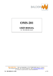
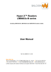
2.2
System operation
The reader is powered from the train, typically 110VDC.
The beacon is remotely powered by the reader's 125 KHz unmodulated transmitter.
Once powered, the beacon transmits at 6.78MHz enabling the reader to generate the localisation signal when
the two are vertically aligned. These signals (S1 and S2) are sent to an on-board controller.
The beacon also transmits identification data by modulating the 6.78MHz carrier. This identification information
is sent on the "Data-TX" interface.
The other signals shown on the diagram below are used for reader control.
.
110Vdc
Gestion
Controldu
lecteur
Alimentation
Power
supply
0Vin
S1
S2
Localisation
Téléalimentation
Remote power
Identification
Pres 125KHz
Pres Tag
BF Operation)
BF (Good
(Bon Fonctmt)
Cde Test
(RS422)
Data Tx
(RS422)
125KHz
6,78MHz
BEACON
2.3
Simplified description
As soon as the beacon receives remote power from the reader it starts transmitting its identifier and continues
doing so until leaving the reader's field. This identifier is in turn transmitted by the reader on its "Data-TX"
interface without interruption until the beacon leaves the reader's field.
Either S1 (or S2, depending on the direction of train travel) becomes active on entering the localisation zone
and the two signals switch polarities simultaneously when reader and beacon are vertically aligned. On leaving
the zone S2 (or S1) becomes inactive. The order (S1 then S2 or S2 then S1) depends on the train's direction of
travel.
The reader includes a diagnostic function allowing monitoring of the 125 KHz transmitter and data reception.
The on-board controller can also communicate with the reader using setup and control commands.
.
BALOGH SA
189, rue d’Aubervilliers - C.P. 97 75886 PARIS Cedex 18 – France Tél : 33 (0)1 44 65 65 00 Fax : 33 (0)1 44 65 65 10 web : http://www.balogh-rfid.com S.A. à Directoire au Capital de 800 000 € - RCS B PARIS 582 061 073
Réf : MU-MOS-200-1.4-EN
p 5/26
MOS-200
3 SAFETY RECOMMANDATIONS
The safety studies performed on the BRS system (consisting of an on-board reader MOS200 and a ground
beacon OMS201), whose main function is to "provide the on-board controller with data allowing localisation of
the train", are compliant with the safety requirements SIL 4.
The safety manual refers to requirements whose application is the user's responsibility. These requirements
are explicitly mentioned in each relevant paragraph below.
All the recommendations are summarised in the table below showing the correspondence between the safety
manual and the user manual.
3.1
Mechanical
References in documents
Requirements for user
Reason
The metallic environment of the sub-systems
must comply with BALOGH SA
requirements.
MU-MOS-200.EN
(reader MOS-200)
MU-OMS-201.EN
(beacon OMS-201)
A reduced reader-beacon communication
range could cause loss of localisation
precision.
§4.4 Environmental
constraints for
reader.
§4.4 Environmental
constraints for
beacon.
The cable-side connector must comply with
BALOGH SA requirements.
Compatibility (mechanical and electrical)
non-compliant with standards and
expected requirements.
§10.2 Connector for
cable
na
The cable must comply with BALOGH SA
requirements.
Compatibility (mechanical and electrical)
non-compliant with standards and
expected requirements.
§10.3 Type of cable
to use.
na
Connections must be carried out and
checked by the user according to BALOGH
SA instructions.
System operation in non-optimal
conditions (protection loss or absence for
inputs/outputs against external damage)
§10 Connections
na
Fastening of sub-systems must be carried
out and checked by the user according to
BALOGH SA instructions.
A reduced reader-beacon communication
range could cause loss of localisation
precision. Data transmission to controller
at the wrong moment.
§4.1 Mechanical
specifications §4.2
Installation
drawings.
§4.1 Mechanical
specifications §4.2
Installation
drawings.
Positioning of sub-systems in axes X, Y & Z
must be carried out and checked by the user
according to BALOGH SA instructions.
A reduced reader-beacon communication
range could cause loss of localisation
precision. Data transmission to controller
at the wrong moment.
§4.3 Positioning
constraints for
reader.
§4.3 Positioning
constraints for
beacon.
Instructions for operation provided by
BALOGH SA guaranteeing radio
communication must be carried out by the
user.
A reduced reader-beacon communication
range could cause loss of localisation
precision.
§4.3 Positioning
constraint for reader
"distance H".
§4.3 Positioning
constraint for reader
"distance H".
Note: na = not applicable
BALOGH SA
189, rue d’Aubervilliers - C.P. 97 75886 PARIS Cedex 18 – France Tél : 33 (0)1 44 65 65 00 Fax : 33 (0)1 44 65 65 10 web : http://www.balogh-rfid.com S.A. à Directoire au Capital de 800 000 € - RCS B PARIS 582 061 073
Réf : MU-MOS-200-1.4-EN
p 6/26
MOS-200
3.2
Electrical
References in documents
Requirements for user
Reason
MU-MOS-200.EN
(reader MOS-200)
MU-MOS-200.EN
(reader MOS-200)
110VDC power provided by train must
comply with requirements specified by
BALOGH SA.
Non-safety recommendation. No system
operation
§2.2 System
operation "Power
supply"
User must take necessary precautions in
order to avoid incorrect encoding of ground
beacon.
A wrong ground beacon identifier will be
transmitted "as is" to the on-board
controller
At the controller, the user must provide a
means of extracting the beacon identifier
from a continuous data stream transmitted
from the BRS system through the Data-TX
interface and a means of checking data
transmission integrity for this identifier.
The BRS system performs no checking
of data transmission integrity (signals:
RS422_Data Tx+ & RS422_Data Tx-).
§7
IDENTIFICATION
INTERFACE
"Data-TX".
na
At the controller, the user must provide a
means of checking coherence for signals S1
& S2 by examining their change of state and
a means of determining the localisation
instant
The BRS system performs no checking
of localisation information (signals:
TOR_S1 & TOR_S2)
§6 LOCALISATION
SIGNALS
na
The user must use all the safety data (DataTX, S1 & S2) provided by the BRS system in
order to perform the train localisation
function.
Necessary operating conditions providing
a guaranteed Safety Integrity Level SIL4
for the BRS system.
§6 POSITIONING
SIGNALS. §7
IDENTIFICATION
INTERFACE
"Data-TX".
na
na
na
§5 Encoding of
beacon identifier.
Note: na = not applicable
BALOGH SA
189, rue d’Aubervilliers - C.P. 97 75886 PARIS Cedex 18 – France Tél : 33 (0)1 44 65 65 00 Fax : 33 (0)1 44 65 65 10 web : http://www.balogh-rfid.com S.A. à Directoire au Capital de 800 000 € - RCS B PARIS 582 061 073
Réf : MU-MOS-200-1.4-EN
p 7/26
MOS-200
4 MECHANICAL SPECIFICATION
4.1
Dimensions
SAFETY RECOMMENDATION – SIL4
Fastening of sub-systems must be carried out
and checked by the user according to
BALOGH SA instructions.
Dimensions of bare casing:
•
•
•
Length = 385mm
Width = 256mm
Height = 68mm
•
•
The length is augmented by the connector and the incoming cable.
Reader must be secured on metallic plate whose width exceeds casing by at least 20mm.
Overall dimensions:
•
•
•
Length including connector = 470mm approx.
Overall length = 600mm approx depending on cable type
Overall width including metallic plate = 296mm minimum
The reader is fastened using 6 screws Ø 6mm.
Recommended tightening torque is 5Nm.
4.2
Installation diagrams
4.2.1 Perspective
BALOGH SA
189, rue d’Aubervilliers - C.P. 97 75886 PARIS Cedex 18 – France Tél : 33 (0)1 44 65 65 00 Fax : 33 (0)1 44 65 65 10 web : http://www.balogh-rfid.com S.A. à Directoire au Capital de 800 000 € - RCS B PARIS 582 061 073
Réf : MU-MOS-200-1.4-EN
p 8/26
MOS-200
4.2.2 Bottom view
approx. depending on cable type
4.2.3 Side view
approx. depending on cable type
4.2.4 End view
BALOGH SA
189, rue d’Aubervilliers - C.P. 97 75886 PARIS Cedex 18 – France Tél : 33 (0)1 44 65 65 00 Fax : 33 (0)1 44 65 65 10 web : http://www.balogh-rfid.com S.A. à Directoire au Capital de 800 000 € - RCS B PARIS 582 061 073
Réf : MU-MOS-200-1.4-EN
p 9/26
MOS-200
4.3
Positioning constraints for reader
SAFETY REQUIREMENT
– SIL4
CONTRAINTE
DE SECURITE
– SIL4
Positioning
of
sub-systems
in
axes
X,
Y & Zêtre
Les fixations des sous-systèmes doivent
must
be carried
out and checked
by the user
assurées
et contrôlées
par l’utilisateur,
selon
according
to BALOGH
SAle instructions.
des consignes
émis par
constructeur.
•
•
•
•
•
The reader must be installed longitudinally (long side of reader parallel to track)
The reference axis for localisation is engraved on the casing and is 29 mm off-centre (opposite side to
connector).
By taking this offset into account, the reader can be installed with the connector end pointed either to
the front or the back of the train.
The vertical separation H between the bottom of the reader and the top of the beacon must be between
60mm and 200mm.
Tolerances on position to be taken into account for installation (see note 1):
Lateral and angular tolerances are defined for a reader-beacon pair. The indications in the table below
concerning the reader's position on the train and the beacon position on the track are only suggestions.
Reader to
beacon
Reader to
train
Beacon to
track
∆Y
Lateral offset
(see note 2)
+/- 10mm
+/- 2mm
+/- 8mm
ΘX
Tilt in vertical
(lateral) plane
+/- 10°
+/- 2°
+/- 8°
ΘY
Tilt in vertical
(longitudinal) plane
+/- 15°
+/- 3°
+/- 12°
ΘZ
Rotation in
horizontal plane
(top view)
+/- 5°
+/- 1°
+/- 4°
BALOGH SA
189, rue d’Aubervilliers - C.P. 97 75886 PARIS Cedex 18 – France Tél : 33 (0)1 44 65 65 00 Fax : 33 (0)1 44 65 65 10 web : http://www.balogh-rfid.com S.A. à Directoire au Capital de 800 000 € - RCS B PARIS 582 061 073
Réf : MU-MOS-200-1.4-EN
p 10/26
MOS-200
Note 1:
•
The position and angular tolerances for each reader-beacon pair must be met. In order to achieve this
end, the tolerances for an individual reader (or beacon) can be relaxed.
These tolerances are additive: a reader-beacon pair with all tolerances at their maximum values will
operate correctly.
•
Note 2:
•
•
•
4.4
The maximum lateral offset for correct operation is +/- 50mm. Within this interval product performance
is guaranteed.
The maximum lateral offset for functional operation is +/- 80mm. At this offset, communication and
localisation are possible, however without guaranteed performance (in particular for precision).
Tolerances shown in the table must be adhered to during installation so that performance is maintained
during movement given that small deviations (vibrations…) occur.
Environmental constraints for reader
•
•
SAFETY REQUIREMENT
– SIL4
CONTRAINTE
DE SECURITE
– SIL4
The
of the sub-systems
Les metallic
fixationsenvironment
des sous-systèmes
doivent être
must
comply
BALOGH
requirements.
assurées
et with
contrôlées
parSA
l’utilisateur,
selon
des consignes émis par le constructeur.
The distance between two readers on the same train must be greater than 5 metres (500 cm).
The reader must be secured on a metallic plate of dimensions 385mm x 296mm (width exceeds casing
by at least 20mm on each of the longer sides)
BALOGH SA
189, rue d’Aubervilliers - C.P. 97 75886 PARIS Cedex 18 – France Tél : 33 (0)1 44 65 65 00 Fax : 33 (0)1 44 65 65 10 web : http://www.balogh-rfid.com S.A. à Directoire au Capital de 800 000 € - RCS B PARIS 582 061 073
Réf : MU-MOS-200-1.4-EN
p 11/26
MOS-200
•
There must be a metal-free zone around the reader as indicated in the diagram below (colour = zone
without metal) :
Cross section (lateral):
Metallic backplate
METAL-FREE
ZONE
Cross section (longitudinal):
Metallic backplate
METAL-FREE
ZONE
BALOGH SA
189, rue d’Aubervilliers - C.P. 97 75886 PARIS Cedex 18 – France Tél : 33 (0)1 44 65 65 00 Fax : 33 (0)1 44 65 65 10 web : http://www.balogh-rfid.com S.A. à Directoire au Capital de 800 000 € - RCS B PARIS 582 061 073
Réf : MU-MOS-200-1.4-EN
p 12/26
MOS-200
5 ELECTRICAL SPECIFICATION FOR INTERFACES
5.1
Isolated power circuits
There are three isolated power circuits as shown in the diagram below:
GROUP 3
Supply.
110Vdc
110Vdc
0Vin
24Vdc
S1
0V
OV
S2
1MΩ
Data TX
1MΩ
Pres6.78MHz
Shield for
cable &
connector
Electronics
BF
Pres125
Cde Test
GROUP 2
0V
GROUP 1
5.2
Power supply
Power supply voltage to reader: 110VDC as specified in EN50155.
Operation is guaranteed for voltages in the range: 77VDC to 137.5VDC.
Power supply current: 250mA (typical, rated, not starting) at 110VDC
5.3
Digital Outputs
Reader's internal power supply produces 24VDC regulated.
Name
Type
Voltage min
high state
@ Current max
Rated voltage for
high state
S1 & S2
Pres125KHz (S3)
Pres6.78MHz (S4)
BF (S5)
Digital output
Digital output
Digital output
Digital output
19V
15V
19V
19V
40mA
40mA
40mA
40mA
24V
24V
24V
24V
5.4
Cde-Test and Data-Tx : RS 422 interfaces
The interfaces "Cde-Test" et "Data-Tx" are RS422 differential pairs compliant with TIA/EIA-422-B.
The output stage has an impedance of 120Ω. It may be necessary to adapt the lines at the controller end with a
120Ω resistor.
BALOGH SA
189, rue d’Aubervilliers - C.P. 97 75886 PARIS Cedex 18 – France Tél : 33 (0)1 44 65 65 00 Fax : 33 (0)1 44 65 65 10 web : http://www.balogh-rfid.com S.A. à Directoire au Capital de 800 000 € - RCS B PARIS 582 061 073
Réf : MU-MOS-200-1.4-EN
p 13/26
MOS-200
6 LOCALISATION SIGNALS
SAFETY REQUIREMENT
– SIL4
CONTRAINTE
DE SECURITE
– SIL4
être
Lesuser
fixations
desallsous-systèmes
doivent S1
The
must use
the safety data (Data-TX,
assurées
et
contrôlées
par
l’utilisateur,
selon
& S2) provided by the BRS system in order to
des consignes
émis par lefunction.
constructeur.
perform
the train positioning
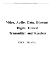
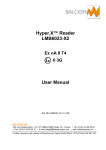
The signals S1 and S2 provide information about
localisation and the communication zone
.
These signals allow:
•
•
beacon detection with an indication of entrance into and exit out of the communication zone
beacon localisation
X
X’
S1
S2
Direction XX’
Entrance into
communication zone
Direction X’X
Exit out of
communication zone
Exit out of
communication zone
Beacon
Localisation
Entrance into
communication zone
For the direction XX’, beacon detection is provided by the rising edge of signal S2 from '0' to ‘1’.
Beacon localisation information is provided by the simultaneous rising of S1 and the falling of S2. Beacon
disappearance information is given by the falling edge of S1.
For the direction X’X, beacon detection is provided by the rising edge of signal S1 from '0' to ‘1’.
Beacon localisation information is provided by the simultaneous rising of S2 and the falling of S1. Beacon
disappearance information is given by the falling edge of S2.
The two signals S1 and S2 are generated by two independent circuits (safety requirement). The simultaneous
switching of S1 and S2 may not happen at exactly the same time. This represents the measurement precision
and corresponds to a distance of less than 5cm.
The controller must verify
•
•
the coherence of signals S1 and S2
that the "simultaneous" switching of S1 and S2
occur at a maximum separation of +/-5cm
SAFETY REQUIREMENT
– SIL4
CONTRAINTE
DE SECURITE
– SIL4
At
thefixations
controller,des
the user
must provide doivent
a meansêtre
of
Les
sous-systèmes
checking
coherence
for signals
& S2 by selon
assurées
et contrôlées
parS1
l’utilisateur,
examining
their change
of state
and a means of
des consignes
émis par
le constructeur.
determining the localisation instant
It is the responsibility of the controller to process the special cases of the reader at rest just above the beacon
and incoherent signals S1 and S2 (e.g. S1 without S2 or vice versa).
The outputs S1 are S2 are digital: binary ‘0’ = 0V and ‘1’ = 24VDC (19V @ 40mA max)
BALOGH SA
189, rue d’Aubervilliers - C.P. 97 75886 PARIS Cedex 18 – France Tél : 33 (0)1 44 65 65 00 Fax : 33 (0)1 44 65 65 10 web : http://www.balogh-rfid.com S.A. à Directoire au Capital de 800 000 € - RCS B PARIS 582 061 073
Réf : MU-MOS-200-1.4-EN
p 14/26
MOS-200
7 IDENTIFICATION INTERFACE
Data-TX
‘Data-TX’ carries the identifier received from the beacon.
The signal sent to the controller is a binary signal,
encoded either NRZ or FM0 depending on the type of
reader MOS-200:
- MOS-200-FM0 for Data Tx in FM0 coding
- MOS-200-NRZ for Data Tx in NRZ coding
SAFETY REQUIREMENT
– SIL4
CONTRAINTE
DE SECURITE
– SIL4
At
thefixations
controller,des
the sous-systèmes
user must providedoivent
a meansêtre
of
Les
extracting
identifier
from a continuous
assuréesthe
et beacon
contrôlées
par l’utilisateur,
selon
data
stream transmitted
the BRS system
des consignes
émis par from
le constructeur.
through the Data-TX interface and a means of
checking data transmission integrity for this
identifier.
For both types, the date transmission rate is 62.5kbits/s, i.e. a bit duration of 16µs.
When the reader goes over the beacon, Data_Tx carries the beacon identifier data, unless the signal BF is low
(‘0’) in which case, no message is sent.
When the reader is not above the beacon, Data Tx is determined by state of the BF signal:
When BF is high (‘1’), the reader is considered to be working correctly, and the RS422 levels are at rest: Tx+ at
‘1’, Tx- at ‘0’.
When BF is low (‘0’), the reader is considered to be faulty, and the RS422 levels are active: Tx+ at ‘0’, Tx- at
‘1’.
The RS422 link for the transmission of the Data-Tx signal is simplex (one-way). The reader sends either the
beacon identifier or the BF information, no reply or command sent by the controller reaches the reader.
The reader does not format the data received from the beacon – no start or stop or other bits are added. If such
formatting is required, it must be included in the encoded beacon data.
Note: If the reader is not powered, both RS422 levels for Data-Tx are at 0V.
7.1
Example for NRZ output
While passing over a beacon, Data-TX will typically show the following behaviour:
- Indication of BF state (before encountering beacon)
- Start of message - preamble of 72bits NRZ at ‘1’.
- Separator 2 bits NRZ at ‘1’.
- message as frame of 144bits NRZ.
- Separator 2 bits NRZ at ‘1’.
- message as frame of 144bits NRZ.
- Separator 2 bits NRZ at ‘1’.
- message as frame of 144bits NRZ
- Separator 2 bits NRZ at ‘1’.
- Start of message - preamble of 72bits NRZ at ‘1’.
- Separator 2 bits NRZ at ‘1’.
- message as frame of 144bits NRZ.
- Etc…
- Incomplete frame due to beacon exiting the communication zone.
- Indication of BF state (after encountering beacon)
Due to beacon start-up time, the first frame received by the reader will be incomplete, i.e. the first bits received
will be somewhere in the middle of the frame.
As long as the beacon remains within the communication zone, the reader receives data from the beacon and
transmits this continuously to the controller. If the reader comes to rest above the beacon, the controller will
receive frames continuously until the reader moves past the beacon and leaves the communication zone.
The beacon transmits continuously. At the end of a frame, it immediately begins retransmitting the same frame
from the beginning again.
BALOGH SA
189, rue d’Aubervilliers - C.P. 97 75886 PARIS Cedex 18 – France Tél : 33 (0)1 44 65 65 00 Fax : 33 (0)1 44 65 65 10 web : http://www.balogh-rfid.com S.A. à Directoire au Capital de 800 000 € - RCS B PARIS 582 061 073
Réf : MU-MOS-200-1.4-EN
p 15/26
MOS-200
The number of frames transmitted depends on the time the reader and beacon remain within the
communication zone.
Example of RS422 levels for signal Data Tx:
Beacon absent
BF valid =’1’
Beacon present
BF non valid =’0’
BF valid =’1’
NRZ frame with
NRZ frame with
BF valid =’1’
BF non valid =’0’
5V
Data Tx+
0V
5V
Data Tx-
7.2
0V
Example for FM0 output
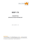
Data sequence showing FM0 coding:
Data
1
0
1
1
0
1
0
0
Clock
Data coded
FM0
16µs
8µs 8µs
While passing over a beacon, Data-TX will typically show the following behaviour:
- Indication of BF state (before encountering beacon)
- Start of message - preamble of 72bits at ‘1’ encoded FM0 (1152µs)
- Separator 2 bits FM0 (32µs)
- message as frame of 144bits FM0 (2304µs).
- Separator 2 bits FM0 (32µs)
- message as frame of 144bits FM0 (2304µs).
- Separator 2 bits FM0 (32µs)
- message as frame of 144bits FM0 (2304µs).
- Separator 2 bits FM0 (32µs)
- Start of message - preamble of 72bits at ‘1’ encoded FM0 (1152µs)
- Separator 2 bits FM0 (32µs)
- message as frame of 144bits FM0 (2304µs).
- etc…
- Incomplete frame due to beacon exiting the communication zone.
- Indication of BF state (after encountering beacon)
Due to beacon start-up time, the first frame received by the reader will be incomplete, i.e. the first bits received
will be somewhere in the middle of the frame.
BALOGH SA
189, rue d’Aubervilliers - C.P. 97 75886 PARIS Cedex 18 – France Tél : 33 (0)1 44 65 65 00 Fax : 33 (0)1 44 65 65 10 web : http://www.balogh-rfid.com S.A. à Directoire au Capital de 800 000 € - RCS B PARIS 582 061 073
Réf : MU-MOS-200-1.4-EN
p 16/26
MOS-200
As long as the beacon remains within the communication zone, the reader receives data from the beacon and
transmits this continuously to the controller. If the reader comes to rest above the beacon, the controller will
receive frames continuously until the reader moves past the beacon and leaves the communication zone.
The beacon transmits continuously. At the end of a frame, it immediately begins retransmitting the same frame
from the beginning again.
A complete frame consists of 512 bits (8192µs):
• 72 bits FM0 at ‘1’
• 4 separators consisting of 2 bits each
• 3 identifiers 144bits FM0
• Total time
:
:4x 32µs =
:3x2304µs =
:
1152µs
128µs
6912µs
8192µs
These frames repeat endlessly and are all identical. The number of frames transmitted depends on the time the
reader and beacon remain within the communication zone.
Example of RS422 levels for signal Data Tx:
Beacon absent
BF valid =’1’
BF non valid =’0’
Beacon present
BF valid =’1’
FM0 frame with
FM0 frame with
BF valid =’1’
BF valid =’0’
5V
Data Tx+
0V
5V
Data Tx-
0V
8 READER STATUS SIGNAL
8.1
Output "Pres125KHz"
The output ‘Pres125KHz’ (S3) indicates correct operation of the reader's 125 KHz transmitter.
‘Pres125KHz’ is at ‘1’ for correct operation, at ‘0’ otherwise. The principle of operation is as follows: a
small antenna connected to a 125 KHz receiver detects a small part of the transmitted power and
generates a binary signal which is sent via the reader's control section to the digital output.
(Pres125KHz)
The output Pres125KHz is digital: binary ‘0’ = 0V, ‘1’ = 24Vdc (15V @ 40mA max)
8.2
Output "Pres6.78MHz"
The output 'Pres6.78MHz’ (S4) indicates that the reader's 6.78 KHz receiver has detected a signal.
This means that a beacon is close and will soon start to transmit its identifier data. This signal is active
whether or not correct beacon data is received. As soon as the 6.78 MHz is no longer detected, this
signal is deactivated. This means that if two beacons are close together, this signal could remain
active, whereas the identifier data will be coming from the other beacon. The detection threshold for the
6.78 MHz receiver is fixed.
The output Pres6.78MHz is digital: binary ‘0’ = 0V (inactive), ‘1’ = 24Vdc (19V @ 40mA max)
BALOGH SA
189, rue d’Aubervilliers - C.P. 97 75886 PARIS Cedex 18 – France Tél : 33 (0)1 44 65 65 00 Fax : 33 (0)1 44 65 65 10 web : http://www.balogh-rfid.com S.A. à Directoire au Capital de 800 000 € - RCS B PARIS 582 061 073
Réf : MU-MOS-200-1.4-EN
p 17/26
MOS-200
8.3
Output "BF"
The output ‘BF’ (S5) indicates correct operation of the reader ("Good operation"); it comprises the
results of tests on the different reader parts; localisation, reception and emission. This signal also
incorporates the results of the following tests:
•
antenna continuity
•
125 KHz transmitter operation (Pres125KHz)
This signal is at '1' when the reader is operating correctly, at '0' otherwise.
The output BF is digital: binary ‘0’ = 0V (inactive), ‘1’ = 24Vdc (19V @ 40mA max)
Note: the Data-TX signal also carries this "Good operation" information – see previous chapter.
8.4
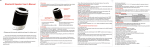
Summary of reader states
Absence
125KHz
Pres125KHz
Pres6.78MHz
Presence 125KHz
Absence
Beacon
Presence
Beacon 1
Absence
Beacon
Presence
Beacon 2
Presence
Beacon 3
Absence
Beacon
No separation between beacon 2 and beacon 3 if
continuous detection of 6.78MHz
Incorrect
BF
reader operation
Correct reader operation
BALOGH SA
189, rue d’Aubervilliers - C.P. 97 75886 PARIS Cedex 18 – France Tél : 33 (0)1 44 65 65 00 Fax : 33 (0)1 44 65 65 10 web : http://www.balogh-rfid.com S.A. à Directoire au Capital de 800 000 € - RCS B PARIS 582 061 073
Réf : MU-MOS-200-1.4-EN
p 18/26
MOS-200
9 SERVICE PORT "Cde-Test"
This is a standard half-duplex serial link on a RS422 differential pair. A 0V reference is available on several
pins of the connector (pins F-H-K-S-T and U, see §10.1).
Although this interface is always available, it is recommended not to send commands to the reader if a beacon
is present.
The data-rate is fixed at 19200bps.
9.1
Character format
1 character 10 bits = 1 start bit + 8 data bits + 1 stop bit
For the data byte, least significant bit is sent first
Start
9.2
Data : 1 byte Stop
Messages sent to and received from reader
9.2.1 Format of commands (status requests)
The format of the messages sent by the controller to the reader is as follows:
STX
•
•
•
CS
<STX> : Start character, 1 byte, value 02H
<Fn> : Function code, 1 byte. The different values that this byte can take on are shown in the table
below
<CS> : Checksum, 1 byte, value = exclusive OR of preceding bytes. The CS is the third and last byte
in message.
Name
F1
F2
F3
F4
F5
F6
F7
F8
Fn
Fn
hexa
20h
21h
22h
23h
24h
25h
26h
28h
Description
Not used
Diagnostic (auto-test) request
Not used
Stop 125KHz transmitter
Start 125KHz transmitter
Read firmware version
Not used
"Good operation" request
BALOGH SA
189, rue d’Aubervilliers - C.P. 97 75886 PARIS Cedex 18 – France Tél : 33 (0)1 44 65 65 00 Fax : 33 (0)1 44 65 65 10 web : http://www.balogh-rfid.com S.A. à Directoire au Capital de 800 000 € - RCS B PARIS 582 061 073
Réf : MU-MOS-200-1.4-EN
p 19/26
MOS-200
9.2.2 Format of replies (status messages)
The format of the replies sent by the reader to the controller is shown below. If the reader receives a request
Fn, then it responds with the message Fn.
STX
•
•
•
•
DATA :
D1
DATA :
D2
CS
<STX> : Start character, 1 byte, value 02H
<Fn> : Function code, 1 byte. The different values that this byte can take on are shown in the table
below.
<DATA>: Supplied by reader as in table below.
<CS> : Checksum, 1 byte, value = exclusive OR of preceding bytes. The CS is the last byte.
Request
F1
F2
Fn
Fn
hexa
20h
21h
D1
D2
00
DEF
Description
Not used
Diagnostic (auto-test) :
DEF (active 1) :
• bit 0 = transmitter error
• bit 1 = receiver error
• bit 2 = processor error
• all other bits 0
Not used
F3
F4
F5
F6
22h
23h
24h
25h
00
00
V1
00
00
V2
F7
F8
26h
28h
BF1
BF2
Firmware version :
• V1 = major index
• V2 = minor index
Not used
Good operation status bits:
BF1 (active 1):
• bit 0 = continuity error for receiving antenna (A-B)1
• bit 1 = continuity error for receiving antenna A
• bit 2 = continuity error for receiving antenna (A-B)2
• bit 3 = continuity error for receiving antenna B
• bit 4 = symmetry fault between antenna A and antenna B.
• bit 5 = reduced power for 125kHz transmitter due to current.
• bit 6 = reduced power for 125kHz transmitter due to voltage.
0Fh
00
00
BF2 (active 1):
• bit 0 = signal present on receiver A
• bit 1 = signal present on receiver B
• bit 2 = reserved
• bit 3 = 125KHz transmitter error
NAK
Important notes :
The diagnostic command F2 briefly turns off the 125 KHz transmitter and briefly turns on a 6.78 MHz
transmitter which consequently prevents detection of any beacon that is present.
The F8 command allows monitoring of all important functions without affecting reader.
BALOGH SA
189, rue d’Aubervilliers - C.P. 97 75886 PARIS Cedex 18 – France Tél : 33 (0)1 44 65 65 00 Fax : 33 (0)1 44 65 65 10 web : http://www.balogh-rfid.com S.A. à Directoire au Capital de 800 000 € - RCS B PARIS 582 061 073
Réf : MU-MOS-200-1.4-EN
p 20/26
MOS-200
9.2.3 Messages sent automatically by the reader
The following message is automatically sent at reader start-up. No reply should be sent by the controller:
STX
•
•
•
D1
D2
CS
<STX> : Start character, 1 byte, value 02H
<Fn> : Function code, 1 byte. The different values that this byte can take on are shown in the table
below.
<CS> : Checksum, 1 byte, value = exclusive OR of preceding bytes. The CS is the last byte.
Request
R2
Fn
Fn
hexa
21h
D1
D2
00
DEF
Description
Diagnostic (auto-test) :
DEF (active 1) :
• bit 0 = transmitter error
• bit 1 = receiver error
• bit 2 = processor error
• all other bits 0
This message is automatically sent when the reader is powered up, after performing the diagnostic tests.
9.2.4 Transmission of beacon identifier
Transmission of the beacon identifier is possible using this service port. This transmission is not guaranteed.
The frame data to be encoded into the beacon can be defined according to customer requirements.
BALOGH SA
189, rue d’Aubervilliers - C.P. 97 75886 PARIS Cedex 18 – France Tél : 33 (0)1 44 65 65 00 Fax : 33 (0)1 44 65 65 10 web : http://www.balogh-rfid.com S.A. à Directoire au Capital de 800 000 € - RCS B PARIS 582 061 073
Réf : MU-MOS-200-1.4-EN
p 21/26
MOS-200
10 CONNECTORS
The connectors used belong to the UTO series from SOURIAU, size 16, 19 pins, protection index IP67, with
shielding capability compatible with EMI requirements.
The connectors are circular with a bayonet locking ring.
10.1 Connector on reader
The connector on the reader is a 19-pin male socket on a square base (wall mounting).
Part numbers:
• Shell : UTO01619PH
• Pins : RM20M12E8K
The male contacts have a diameter of 1.6mm.
Pin
A
B
C
D
E
F
G
H
J
K
L
M
N
P
R
S
T
U
V
Assignment
110VDC
0VDC
CdeTest_RS422_RXData_TX_422Data_TX_422+
0V
S2
0V
S1
0V
Pres125KHz
Pres6.78MHz
BF (Good Operation)
CdeTest_RS422_TX+
CdeTest_RS422_RX+
0V
0V
0V
CdeTest_RS422_TX-
External front view of socket
(rear view of plug on cable side)
BALOGH SA
189, rue d’Aubervilliers - C.P. 97 75886 PARIS Cedex 18 – France Tél : 33 (0)1 44 65 65 00 Fax : 33 (0)1 44 65 65 10 web : http://www.balogh-rfid.com S.A. à Directoire au Capital de 800 000 € - RCS B PARIS 582 061 073
Réf : MU-MOS-200-1.4-EN
p 22/26
MOS-200
10.2 Connector to mount on cable
SAFETY REQUIREMENT
– SIL4
CONTRAINTE
DE SECURITE
– SIL4
The
connector
must comply
with
Les cable-side
fixations des
sous-systèmes
doivent
BALOGH
SA requirements.
être assurées
et contrôlées par
l’utilisateur, selon des consignes émis
The cable-side connector is a female plug with part numbers:
- Shell: UTO61619SH
2
2
- Pin sockets: RC16M23K - for wire gauges 0.5mm to 1,5mm (AWG16 to AWG20).
- Backshell and clamp: UTOS16JCSL (long model for cables ∅13.5 to 18mm).
These are typical references. See SOURIAU product documentation for exact available references.
The pin sockets of the plug should be chosen according to the conductor gauges used in the cable. The above
2
2
part number is suitable for gauges from 0.5mm to 1.5mm (AWG16 to AWG20). See SOURIAU product
documentation for other possible references.
The backshell for the plug should be chosen according to the outer cable diameter. The above part number is
suitable for cable diameters from 13.5mm to 18mm. See SOURIAU product documentation for other possible
references.
10.3 Cable type
The cable to be used must have the following characteristics:
• 19 conductors
• common shield with 360° contact to connector.
• twisted pairs preferred for serial links.
2
2
• conductor cross-section between 0.5 mm and 1.5 mm .
• outer cable diameter between 13.5mm and 18mm.
• cable linear capacity less than 100pF/m.
• maximum length: 200m.
SAFETY REQUIREMENT
– SIL4
CONTRAINTE
DE SECURITE
– SIL4
The
cable
must
comply
with
BALOGH
SA
Les fixations des sous-systèmes
requirements
doivent être assurées et contrôlées
par l’utilisateur, selon des consignes
Individual conductors must be connected to contacts using a crimping tool.
The shield must be correctly connected to the backshell:
the clamp must make 360° contact with the shield. S ee
SOURIAU documentation for the correct procedure.
SAFETY REQUIREMENT
– SIL4
CONTRAINTE
DE SECURITE
– SIL4
Connections
must des
be carried
out and
Les fixations
sous-systèmes
checked
by the
user et
according
to
doivent être
assurées
contrôlées
par l’utilisateur,
selon des consignes
BALOGH
SA instructions.
émis par le constructeur.
BALOGH SA
189, rue d’Aubervilliers - C.P. 97 75886 PARIS Cedex 18 – France Tél : 33 (0)1 44 65 65 00 Fax : 33 (0)1 44 65 65 10 web : http://www.balogh-rfid.com S.A. à Directoire au Capital de 800 000 € - RCS B PARIS 582 061 073
Réf : MU-MOS-200-1.4-EN
p 23/26
MOS-200
11 VERIFYING READER OPERATION
Reader verification can be done in two cases:
- In the workshop, for example on delivery or before installation. In this case measurements can be
made using several different apparatus, a test cable can be used to connect to the reader in order to
monitor the signals and a PC can be used to emulate the on-board controller.
- Reader installed under train, for regular checks
The MOS-200 reader is entirely immersed in resin. It can neither be disassembled nor repaired. Any permanent
fault or defect found during the verification process will require the reader to be replaced.
The technical procedures described in this chapter need to be carried out by personnel adequately trained in
electronics measurements.
11.1 Testing in workshop
11.1.1 Apparatus required
-
A test cable with 19-pin female plug and individual access to all 19 wires
Power supply 110V / 1A.
An ammeter measuring the current drawn from the power supply, if the power supply has no current
display.
A 2-channel oscilloscope. If not available, either two voltmeters or a circuit with LEDS for visualising the
digital outputs can be used.
An OMS-201 reference beacon centrally mounted on a metallic plate of dimensions 260mm x 180mm.
A metallic plate of dimensions 385mm x 296mm on which the reader under test is to be fixed.
11.1.2 Tests to be performed
-
The MOS-200 reader is connected to the 110VDC power supply. When powered up, the outputs are as
follows :
Pres125KHz
Undetermined
Activation 125 KHz
Pres6.78MHz
BF
Data Tx
Undetermined
Undetermined
≈1ms
Undetermined
1500ms
o
o
o
Test BF ok
Stable output
guaranteed after 1s
A 100ms pulse is generated on the 3 digital outputs "BF", "Pres6.78MHz" and "Pres125 kHz".
Automatic emission of a test pattern that appears on the "Data-Tx" output. This test pattern is
in fact a 62.5 KHz square-wave of duration 1 ms sent by the microcontroller to the 6.78 MHz
transmitter which is then detected by the 6.78 MHz receiver and sent to this output. During this
time the 125 KHz transmitter is turned off, so as not to receive and data from a beacon that
may be present.
Emission of a status message on the output "cde test" (see §9.2.3).
BALOGH SA
189, rue d’Aubervilliers - C.P. 97 75886 PARIS Cedex 18 – France Tél : 33 (0)1 44 65 65 00 Fax : 33 (0)1 44 65 65 10 web : http://www.balogh-rfid.com S.A. à Directoire au Capital de 800 000 € - RCS B PARIS 582 061 073
Réf : MU-MOS-200-1.4-EN
p 24/26
MOS-200
-
With the reader powered up and no beacon:
o current drawn must be between 170mA and 300mA.
o signal BF must be at 1
o signal Pres125KHz must be at 1
-
The beacon is placed before the reader
o signal Pres6.78KHz becomes active (1)
-
Move the beacon past the reader simulating the train movement
o signals S1 and S2 must behave as follows :
X
X’
S1
S2
Start/end of
Communication zone
-
Start/end of
Communication zone
Beacon Localisation
By connecting the serial link "CDE-TEST" to a PC using an RS422-RS232 converter (see connection
diagram below), the "COM-MOS" program can be used to read the beacon identifier.
Converter RS422/232
RX+
PC
RXTX+
A
B
Y
Z
P
V
R
C
TX-
-
READER
CdeTest_RS422_TX+
CdeTest_RS422_TXCdeTest_RS422_RX+
CdeTest_RS422_RX-
Signal "DATA-TX" can be checked with an oscilloscope: signal is present and data rate is 62.5 kbits/s
(bit duration of 16µs).
11.2 Verifying the operation of an installed reader
If the connector can be removed, the use of a long test cable will allow the tests described in the preceding
section to be performed. Similarly if individual access to certain wires is possible between the reader and the
controller, signals can be checked.
If the connector cannot be removed or if wires cannot be accessed individually, then it is the user's
responsibility to implement the necessary test functions in the controller.
BALOGH SA
189, rue d’Aubervilliers - C.P. 97 75886 PARIS Cedex 18 – France Tél : 33 (0)1 44 65 65 00 Fax : 33 (0)1 44 65 65 10 web : http://www.balogh-rfid.com S.A. à Directoire au Capital de 800 000 € - RCS B PARIS 582 061 073
Réf : MU-MOS-200-1.4-EN
p 25/26
MOS-200
12 MAINTENANCE
12.1 Regular maintenance
The MOS-200 reader requires no regular operational maintenance.
The MOS-200 reader should be regularly cleaned to avoid accumulation of dirt on casing.
The MOS-200 reader should be regularly examined for:
•
•
•
•
•
cracks in casing
broken mounting plates
missing mounting screws
correctly tightened mounting screws
connector properly locked in place
The MOS-200 reader operation should be checked regularly according to procedure in the previous chapter.
12.2 Replacement
To replace a MOS-200 reader, proceed as follows:
•
•
•
•
turn the knurled ring of connector 1/3 turn anti-clockwise to disengage plug from socket
remove the 6 mounting screws and lift out the reader, remembering the localisation axis
Put the new MOS-200 reader in the same position, replace 6 mounting screws and tighten to
recommended torque.
Plug in connector and turn knurled ring 1/3 turn clockwise until locked.
Check for correct operation according to above procedure in the previous chapter.
12.3 Recycling
Decommissioned MOS-200 readers should be returned to BALOGH for recycling in accordance with guideline
D3E.
BALOGH SA
189, rue d’Aubervilliers - C.P. 97 75886 PARIS Cedex 18 – France Tél : 33 (0)1 44 65 65 00 Fax : 33 (0)1 44 65 65 10 web : http://www.balogh-rfid.com S.A. à Directoire au Capital de 800 000 € - RCS B PARIS 582 061 073
Réf : MU-MOS-200-1.4-EN
p 26/26