1
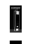
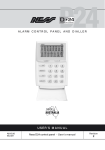
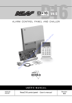
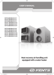
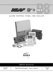
SecurityGuard III
With Two Way Voice Monitoring
Wireless Security System
with GSM Monitoring
& Two Way Voice
Owner's Manual
SECURITYGUARD III Main Unit
Congratulations on selecting SECURITYGUARD III
to protect your family and home.
Your SECURITYGUARD III with its "speak easy"
technology is a revolutionary radio based stateof-the-art alarm system which has been built to
the highest standards of industrial design and
manufacturing.
The many sophisticated and innovative
design features of the SECURITYGUARD III
make the system highly secure as well as
being easy to use.
This Owner's Manual will help you identify the
various parts of your SECURITYGUARD III
system and give you an overview of operation
and functions.
Onboard siren / Speaker
Siren and spoken voice prompts.
GSM Dialler built-in.
Rechargeable Main Battery
(Internal).
Scrolling LED Display
Indicator LED
One flash every 5 sec indicates normal operation.
Control Buttons
Left button
Right button
Adjust Main Volume - Press x 1
Main Volume 1 – 4
Adjust Bell Type - Press x 2
Bell Type 1 – 3
Adjust Bell Volume - Press x 3
Bell Volume 1 – 4 – OFF
Onboard Motion Sensor (PIR)
Emergency over-ride keyswitch
3
Operation
Arm
By Radio Key
By Radio Keypad
Valid
button
Press once.
Low Battery
+[User Code]+
press
System is fully armed
Home Mode (If enabled)
By Radio Key
By Radio Keypad
Valid
button
Press twice.
Low Battery
+[User Code]+
press
System is partially armed
Home2 (If enabled)
By Radio Key
button
Press 3 times.
System is partially armed
Disarm (or to reset alarms)
By Radio Key
By Radio Keypad
Valid
button
Press once.
Low Battery
System is disarmed
press [User Code]+
In these example house plans Armed areas are shown shaded
4
, Disarmed areas shown unshaded.
Operation
Panic Alarm
By Radio Key
By Radio Keypad
Valid
button
Press & hold for
4 seconds.
Alarm
Low Battery
Press both
star keys together
GSM Dialler
to Monitoring
Station
Clearing Displays
button
Press once.
To clear any display,
press the Disarm button
on a Radio Key. To recall
the display press Disarm
again, (unless the display
has been reset by arming
and disarming.)
Emergency Over-ride Key
Only to be used if your remote radio
Keys are lost. Insert key and turn anticlockwise to disable the SECURITYGUARD III. (Store these keys in safe,
hidden place).
SECURITYGUARD III
power off
Turn the key anticlockwise.
SECURITYGUARD III
power on
Turn the key clockwise.
5
Radio Key (RK4)
Operation
RK4 Radio Keys have four buttons for operating your
SECURITYGUARD III.
button to Disarm the system or to siPress the
lence alarms.
button to Arm the system or press
Press the
twice for HOME mode (if enabled on your system.)
Press the
button to sound the Panic alarm.
button for auxiliary functions as proPress the
grammed by your installer.
Battery Replacement
* Example device
number
Your RK4 Radio Keys are sealed units with an expected battery life of 10 years. Low battery warning
might indicate a battery fault or the battery has been
depleted by continuous presses. Contact Ness or
your SGIII dealer for advice.
Radio Keypad (RKP)
Operation
RKP Radio Keypads have a full PIN pad for operating your SECURITYGUARD III using 3 to 6 digit user
codes. Your installer will set up and program the
RKP to suit.
Buttons
Used with your user code to arm the system.
Used with your user code to arm Home mode.
Enter button, used when arming and disarming.
(Press together) Sounds the Panic alarm.
Not used.
Used by your installer only.
Lights
Valid: Flashes once when a valid radio signal is
sent to the Securityguard.
Low Battery: If flashing indicates that the RKP's
internal battery is low. Replace the battery.
Battery Replacement
* Example device
number
Carefully open the RKP Radio Keypad by pushing
both tabs at the top of the unit using a flat-bladed
screwdriver or blunt knife.
Insert a new high energy Lithium 9V battery and
then test the sensor.
Insert the new high
energy Lithium 9V
battery.
6
Main Unit Battery
LOW MAIN Battery
(Battery Powered Systems)
Your SECURITYGUARD III main battery will provide
3-4 month's operation before it must be recharged.
When the "Low Main Battry" message is displayed
you must charge the main battery.
Plug the charger into a mains power outlet and plug
the charging connector into the SECURITYGUARD III
for 24 hours.
Connect the charger
for 24 hours.
The red Indicator LED
will be on while charging.
Motion Sensors (PIR)
Operation
R15 PIR motion sensors can be added to the system
to provide protection in additional rooms.
Maximum detection range is 15m.
Battery Saving Timer
The PIR motion sensors have a unique battery saving
feature which greatly extends battery life.
The Battery Saving Timer conserves the PIR battery
by preventing activation when it detects continuous
motion, such as in a busy room during the day.
Leave the
room.
Wait 5
minutes.
Red light
indicates motion
sensed.
The timer 'wakes' the PIR only when there has been no
motion for 5 minutes. The PIR will ignore any motion if
the timer has not expired. This is normal operation!
To test a PIR, leave the room for at least 5 minutes and
then re-enter. The red light in the PIR will flash to indicate that it has sensed your motion into the room. If you
don't see the red light you may not have waited long
enough - try again.
PIR Battery Replacement
* Example device
number
The PIR motion sensors use a high energy Lithium
9V battery.
Carefully lift off the sensor's cover by unclipping at
the bottom using a flat-bladed screwdriver or blunt
knife.
Insert a new high energy Lithium 9V battery and
then test the sensor.
Unclip cover
at the bottom.
Remove the
cover.
Insert the new high
energy Lithium 9V
battery.
7
Radio Door Bell (RDB)
Operation
Press the Door Bell button to sound the door chime at
the SECURITYGUARD III main unit.
Battery Replacement
* Example device
number
Carefully lift off the RDB Door Bell unit's cover by
unclipping at the bottom using a flat-bladed screwdriver or blunt knife.
Insert a new CR2032 3V Lithium battery and then
test the sensor.
Positive (+)
side up.
Open here.
Remove
cover.
The new battery must be inserted in the battery clip
with the positive (+) side up.
Insert the new
battery. CR2032
3V Lithium
battery.
Radio Panic Button (RPB) Optional
Operation
Press the red Panic button to sound the Panic alarm.
(As programmed by your installer.)
Battery Replacement
* Example device
number
Carefully lift off the Panic Button's cover by unclipping at the bottom using a flat-bladed screwdriver or
blunt knife.
Insert a new CR2477 3V Lithium battery and then
test the sensor.
Positive (+)
side up.
Open here.
Remove
cover.
The new battery must be inserted in the battery clip
with the positive (+) side up.
Insert the new
battery. CR2477
3V Lithium
battery.
8
Radio Micro Reed Switch (RR3)
Operation
RR3 Radio Micro Reed Switches can be installed on
windows and doors to detect opening.
Battery Replacement
* Example device
number
Positive (+) side up.
Carefully lift off the reed switch cover by unclipping
at the bottom using a flat-bladed screwdriver or
blunt knife.
Insert a new CR2032 3V Lithium battery and then
test the reed switch.
The new battery must be inserted in the battery clip
with the positive (+) side up.
RR3
Open here.
Lift battery
out.
Insert the new
battery. CR2032
3V Lithium battery.
Universal Transmitter (RR2) Optional
Operation
Universal Transmitters can be used as window and
door switches (same as Radio Reed Switches) or as a
universal transmitter for other devices as connected
by your installer.
The RR2 also has an onboard vibration analyser with
sensitivity adjustment. This allows optional Nessensor™ vibration sensors to provide wireless protection
of door and window frames, works of art, jewellery
cases, safes and other valuables.
Battery Replacement
* Example device
number
Carefully lift off the Universal Transmitter cover by
unclipping at the bottom using a flat-bladed screwdriver or blunt knife.
A warning sound will be heard when opening the
case - this is normal.
Insert a new high capacity Lithium 9V battery and
then test the transmitter.
Open here.
Remove the
cover.
Insert the new
high energy
Lithium 9V
battery.
9
Radio Smoke Detector
Operation
The SECURITYGUARD III Radio Smoke Detector
(RSM) is a photoelectric smoke detector and on-board
radio transmitter are powered by a single 9V Lithium
battery (supplied).
Alarm signals are delayed by 10 seconds before being sent to allow the on-board sounder to be tested
without triggering the alarm system.
Testing
To test the sounder press and hold the Test button for
at least 2 seconds.
If you hold the Test button for longer than 10 seconds it
will also send an alarm signal to the SECURITYGUARD
III.
Battery Replacement
* Example device
number
Remove the detector from its base by twisting anticlockwise. Replace the battery with a high energy
Lithium 9V battery.
Make sure the red safety bar in the battery compartment folds down under the new battery. The safety bar
ensures that the smoke detector cannot be connected
to the base without the battery fitted.
Twist off.
Insert the new high
energy Lithium 9V
battery.
To replace the detector on the base, line up the slot
on the detector with the alignment arrow on the base
and twist the detector clockwise to lock it in. Test the
smoke detector.
NOTICE
The RSM radio smoke detector is intended for use as an optional and supplementary smoke detection system in
addition to existing smoke alarms as required by relevant building codes.
If there is any doubt as to the suitability of this device for a particular application it is recommended that you seek
advice from the appropriate authorities or professional fire protection services.
Radio Siren
Operation
The Radio Siren may be installed inside the premises
to provide an extra loud noise deterrent in the event of
an alarm.
The Radio Siren is powered by a plug pack which must
always remain on at the power point.
10
Back-To-Base Monitoring
GSM Dialler
Two Way Voice
Your SECURITYGUARD III has a GSM Dialler
which communicates with you or your monitoring station using the GSM mobile telephone
network. This means you don't need a telephone
landline for monitoring.
Your SECURITYGUARD III has Two Way Voice
capabilities which means that in the event of
an alarm you can listen in and talk back to the
premises through the SECURITYGUARD III.
This allows you to verify alarm calls from any
phone, anywhere you are.
The dialler is setup and programmed by your installer at the time of installation. It does not need
any maintenance but should be tested when you
perform your regular system test.
In the event of an alarm, SECURITYGUARD III can
send SMS alerts to your mobile phone and you
can even arm and disarm SECURITYGUARD III
remotely from your mobile phone.
GSM monitoring needs an active mobile phone
SIM card to operate. Central station monitoring
also requires a monitoring account with a monitoring company.
Monitoring Options
Your Mobile Phone
Monitoring Station
24 hour monitoring by a central monitoring
station.
Self monitoring by SMS to your mobile
phone with a two way voice channel.
SMS text alerts
ARE YOU OK?
Two Way Voice
Wireless communication to central
monitoring station via GSM.
11
SECURITYGUARD III Battery Specifications
Model
Battery
SECURITYGUARD III Main Unit
12V 3Ah Sealed Lead Acid (Gel) Battery
Radio Key - 4 button
Sealed housing, not user serviceable
Radio Keypad
High energy Lithium 9V battery*
R15 PIR Motion Sensor
High energy Lithium 9V battery*
Radio Smoke Detector
High energy Lithium 9V battery*
Radio Panic Button
CR2477 3V Lithium battery
RR3 Radio Reed Switch
CR2032 3V Lithium battery
RR2 Universal Transmitter
High energy Lithium 9V battery*
RDB Radio Door Bell
CR2032 3V Lithium battery
* Use only high energy Lithium 9V batteries. Carbon or alkaline batteries are not recommended.
Made In Australia by:
SECURITYGUARD III User's Manual
For the products 106-285 & 106-286 SGIII GSM + Voice models
Rev2 Sep 2011
Document part number 890-410
Photographs are used for illustrative purposes only. Design and specifications may vary.
Ness Corporation manufacturing processes are accredited to ISO9001 quality standards and all possible care and diligence has been applied during
manufacture to ensure the reliable operation of this product. However there are various external factors that may impede or restrict the operation of this
product in accordance with the product’s specification.
These factors include, but are not limited to:
1. Erratic or reduced radio range. Ness radio products are sophisticated low power devices, however the presence of in-band radio signals, high power
transmissions or interference caused by electrical appliances such as wireless routers, cordless phones, computers, TVs and other electronic devices may
reduce the range performance. While such occurrences are unusual, they are possible. In this case it may be necessary to either increase the physical
separation between the Ness receiver and other devices or if possible change the radio frequency or channel of the other devices.
2. Unauthorised tampering, physical damage, electrical interruptions such as mains failure, electrical spikes or lightning.
Copyright Notice
All rights reserved. No part of this publication may be reproduced, transmitted or stored in a retrieval system in any form or by any means, electronic,
mechanical, photocopying, recording, or otherwise, without the prior written permission of Ness.
Ness reserves the right to make changes to features and specifications at any time without prior notification in the interest of ongoing product development
and improvement.
© 2011 Ness Corporation Pty Ltd ABN 28 069 984 372