1
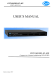
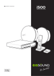
RF Wireless Thermometer 683F03
5. The upper part of LCD of the receiving unit will show remote channel 1 and the temperature reading.
6. After registration complete for sensor 1, put the rubber seal into the cover groove, close the battery cover
tighten the screws, and snap on the bracket stand. Follow the same procedure to register remot sensor 2
and 3.
ON/OFF
Note
After you have placed the sensor in the remote location, observe the receiving unit channel display for that
sensor after 8 minutes. If the (---) dash icon appears and flashes to indicate the signal interruption, rotate the
sensor in 45° steps and wait at least 3 minutes. If no display, move the remote sensor closer to the receiving
unit or repositioning of both receiving unit and remote sensor until reception is observed.
T1/T2
+
Remote Channel Auto Scroll
This devise is equipped with auto scroll “ ” function that when 2 or 3 units of remote sensors are active, it
will automatically cycle through the remote channels 1 to 3.
1. To enable auto scroll function, use “CHANNEL” button to select channel 1, 2, 3 or
auto scroll.
2. To retrieve manually the specific remote sensor temperature reading, press the “CHANNEL” button until
desired channel is displayed.
We greatly appreciate on purchasing our new RF Wireless Thermometer. Engineered and designed with the
latest wireless technology and digital electronics, this device displays the indoor temperature and outside
temperature at up to 3 remote sensors in different locations. It also includes a digital clock with backlight and
a programmable audible alarm.
To ensure proper operation, please read this Instruction manual carefully and keep for future reference.
Battery Installation for your Receiving Unit
This device is designed for easy set up. Anyway, the following steps are required to be done in the proper
sequence. Please insert batteries for receiving unit before doing so for the remote units.
1. Remove the stand (if it is in place) by rotating the rear edge down, press and slide open the battery cover.
2. Insert 2 pcs of AA size batteries with matching (+) and (-) polarity marks on battery compartment. Close
the battery cover and install the stand back.
3. (---) dash icon will flash at upper part of the LCD, wait and ready to register with the remote sensor(s)
signal.
Remote Sensor
Without LCD display
Detachable probe (optional)
With LCD display
TX / HOLD RESET
AAA 1.5V
AAA 1.5V
Bracket Stand
Lift off this part
For your Wireless Remote Sensor registration procedure
1. Lift off the bracket stand by releasing the bottom two fixing snaps.
2. Use a small Phillips screwdriver to remove the screw on the battery cover.
3. Then insert 2pcs of AAA size batteries according to polarity marks on the battery compartment.
4. Once the batteries are inserted, the sensor will be automatically transmit temperature reading at 30 seconds
intervals to the receiving unit. Or use the tip of a ball pen or etc. to press & hold “TX” button for 2
seconds to send the signal to the receiving unit.
Using 6 feet cords Temperature Probe (optional)
Your wireless thermometer is equipped with a 6 feet cord temperature probe for measuring water, soil, freezer
or etc. To use this probe,
• Open the rubber cover of the hole at the side of the remote sensor and insert the probe plug.
(The probe is now active.)
• If the outside temperature is extremely low (below 10°C) extend the 6 feet probe cord, leave probe sensor
outside, and keep the remote sensor unit inside to avoid freezing up the battery.
• The temperature readings will be displaying the remote channel matched to the remote sensor location
where the probe has been inserted.
Maximum and Minimum Temperature Memory
This device records and displays max./min temperature readings to the receiver and remote sensor
locations. (The max./min. readings will be only shown for the channel and the indoor (local temp.) actually
on display).
• To read max./min. records for 5 seconds press “MIN/MAX” button.
• Erase all the max./min. records displayed on screen, press “CLEAR/ ” button.
Setting the Clock
1. To et the clock manually, press & hold “MODE” button for 2 seconds. 12 or 24 hr. is blinking.
2. Use the “+” or “-” button to select 12/24 hr. and then press “MODE” button to confirm.
3. The hour digits will blink. Using “+” or “-” button to set required time (each press the button will
increase and decrease the digits by one. Holding the button will cause the setting to change rapidly).
4. Press “MODE” button again to confirm. The minutes will blink. Repeat the same procedure to enter
minutes, offset, year, month and date.
Dual Daily Alarm
will flash.
1. To starting setting time alarm Press & hold “CLEAR/ ” button for 2 seconds. The bell icon
2. Using “+” or “-” button to select bell icon
or . Pressing “CLEAR/ ” button to confirm.
3. The hour digits will blink. Using “+” or “-” button to set desired hour. Press “CLEAR/ ” button to confirm.
4. The minute digits will blink. Follow the same procedure to enter minute.
5. Also follow the same procedure (1 to 4) to set alarm 2.
The selected bell “ ” icon for the alarm will displayed indicating that the alarm above is now activated.
When the alarm beeps, press “SNOOZE/LIGHT” button to temporarily paused the alarm for 8 minutes.
The bell “ ” icon and snooze “SNZ” icon will flashing. Press any button to stop the alarm.
6. Press “CLEAR/ ” button to read alarm time for 5 seconds.
7. To enable or disable the alarm function, press “ ON/OFF” button.
SNOOZE/LIGHT button
• Press the button once for a 5 second extended backlight.
• When the alarm beeps, press the button to temporarily paused the alarm for 8 minutes.
°F/°C - button
• Press the button to select temperature reading in Celsius or Fahrenheit.
Alert for Indoor Temp and each Remote channels procedure
This device can be programmed to alert that the temperature goes up or below a pre-determined range at the
receiving unit or any of the 3 remote sensors locations
a. Press “ALERT” button to enable or disable temperature alert. Press & hold “ALERT” button for 2 seconds
to start setting.
b. The “ ” upper/lower icon will blink. Use “+” or “-” button to select Indoor, Channel 1, 2 or 3 (if 3
sensors are available). Press ‘ALERT” button to confirm.
c. The “ ” upper limits and (---) icons will blink. Using “+” or “-” button to enter upper limit. Press“ALERT”
button to confirm.
d. The “ ” lower limit icon will blink. Use “+” or “-” button to enter lower limit, then press “ALERT”
button to confirm.
e. To set alert values for other registered channel, select the desired channel and repeat procedure from
(a to d).
The “ ” upper/lower icon appears and all alarms previously set for each channel and indoor become active.
When the alert ranges are reached or passed, alarm will occur and upper/lower icon will flash.
Temperature Trend Indicator
Arrow icon will atomatically show the temperature trend of the channel.
Temperature is increasing.
Remain unchanged.
Specification
Displayed indoor temperature range
Recommended remote sensor operating range
Sensor with LCD display
Sensor without LCD display
Detachable outdoor probe
Batteries
Thermometer station
Remote Sensor
Battery life (status)
Receiving unit
Remote sensor
Transmission range
Temperature sampling
Thermometer station
Remote Sensor
Transmission frequency
Clock
:
0°C to +50°C (+32°F to +122°F)
: 0°C to +50°C (+32°F to +122°F)
: -20°C to +50°C (-4°F to +122°F)
: -50°C to +70°C (-58°F to +158°F)
: DC 1.5V AA size x 2 pcs.
: AAA size x 2 pcs.
: Typical 1 year
: Typical 6 months
: Max. 30 meters open area
:
:
:
:
every 10 seconds
every 8 seconds
433.92 MHz.
Quartz
This device could be sensitive for electrostatic discharge. If electrostatic discharge or malfunctioning occurs,
please reset this unit.
Temperature is decreasing.
Installation of Remote Sensor(s)
Locating remote sensor in clear open area can attain a maximum 30-meter transmission distance. Actual
transmission distance can be reduced by interference from building, obstruction or a screen between the
remote sensor(s) and the receiving unit.The Remote sensor(s) can be hung on a flat wall by means of a wood
screw. And also a pull stand that you desire a horizontal surface mount.
Battery Replacement
A “ ” low battery icon will appear on the display of the receiving unit. when the batteries of the receiving
unit and remote sensor(s) need replacement. For replacing batteries always use new batteries as specified in the
user manual. Do not mix old and new batteries as the old ones may leak.
Troubleshooting for losing Signals
If without obvious reasons the display for a particular channel goes (---) dash, check:
• The remote unit of that channel is still in place.
• The batteries of both receiving and remote unit. Replace as necessary.
• The transmission is within range and path is clear of obstacles and interference. Shorten the distance when
necessary.
• Signals from other household devices, such as bells, home security system and entry controls, it may
interfere with those of this product and cause temporarily reception failure. This is normal and it doesn’t
affect the general performance of the product. The transmission and reception of temperature readings
will resume once recedes.
Precautions
a. Do not clean the units with abrasive or corrosive compound. It may scratch the plastic parts and corrode
the electronic circuits.
b. Do not subject the units to excessive force shock, dust, temperature or humidity, which may result in
malfunction, shorter electronic life span, damaged battery and distorted parts.
c. Do not tamper with these units’ internal components. Doing so will invalidate the warranty on the unit
and may cause unnecessary damaged battery and distorted parts.
d. Do not subject the units to excessive exposure to direct sunlight. Although the remote sensor is splashproof design. never immerse it in water or expose it to heavy rain.
e. Always read the users manual thoroughly before operating the unit.
071-683102-001901