1
ControlNet
Communications
For PanelView Plus and
PanelView Plus CE Terminals
User Manual
Important User Information
Solid state equipment has operational characteristics differing from those of
electromechanical equipment. Safety Guidelines for the Application,
Installation and Maintenance of Solid State Controls (publication SGI-1.1
available from your local Rockwell Automation sales office or online at
http://literature.rockwellautomation.com) describes some important
differences between solid state equipment and hard-wired electromechanical
devices. Because of this difference, and also because of the wide variety of
uses for solid state equipment, all persons responsible for applying this
equipment must satisfy themselves that each intended application of this
equipment is acceptable.
In no event will Rockwell Automation, Inc. be responsible or liable for
indirect or consequential damages resulting from the use or application of
this equipment.
The examples and diagrams in this manual are included solely for illustrative
purposes. Because of the many variables and requirements associated with
any particular installation, Rockwell Automation, Inc. cannot assume
responsibility or liability for actual use based on the examples and diagrams.
No patent liability is assumed by Rockwell Automation, Inc. with respect to
use of information, circuits, equipment, or software described in this manual.
Reproduction of the contents of this manual, in whole or in part, without
written permission of Rockwell Automation, Inc., is prohibited.
Throughout this manual, when necessary, we use notes to make you aware
of safety considerations.
WARNING
IMPORTANT
ATTENTION
Identifies information about practices or circumstances that can cause
an explosion in a hazardous environment, which may lead to personal
injury or death, property damage, or economic loss.
Identifies information that is critical for successful application and
understanding of the product.
Identifies information about practices or circumstances that can lead
to personal injury or death, property damage, or economic loss.
Attentions help you identify a hazard, avoid a hazard, and recognize
the consequence
SHOCK HAZARD
Labels may be on or inside the equipment, for example, a drive or
motor, to alert people that dangerous voltage may be present.
BURN HAZARD
Labels may be on or inside the equipment, for example, a drive or
motor, to alert people that surfaces may reach dangerous
temperatures.
Table of Contents
Preface
Topics Covered. . . . . . . . . . . . . . . . . . . . . . . . . . . . . . . . . . . 5
Software Requirements . . . . . . . . . . . . . . . . . . . . . . . . . . . . . 5
Additional Resources. . . . . . . . . . . . . . . . . . . . . . . . . . . . . . . 6
Chapter 1
Install a ControlNet
Communication Module
Objectives. . . . . . . . . . . . . . . . . . . . . . . . . . .
Install Module on 700-1500 Terminals . . . . . .
Install Module on 400-600 Terminals . . . . . . .
ControlNet Module Connectors . . . . . . . . . . .
Connect the Module to a ControlNet Network
.
.
.
.
.
.
.
.
.
.
.
.
.
.
.
.
.
.
.
.
.
.
.
.
.
.
.
.
.
.
.
.
.
.
.
.
.
.
.
.
.
.
.
.
.
.
.
.
.
.
.
.
.
.
.
. 7
. 7
. 9
11
12
Chapter 2
Configure Unscheduled
Communications
Objectives. . . . . . . . . . . . . . . . . . . . . . . . . . . . . . . . . . . . . . 15
Software Requirements . . . . . . . . . . . . . . . . . . . . . . . . . . . . 15
Configure Communications . . . . . . . . . . . . . . . . . . . . . . . . . 16
Chapter 3
Configure Scheduled
Communications
Objectives. . . . . . . . . . . . . . . . . . . . . . . . . . . . . . .
Software Requirements . . . . . . . . . . . . . . . . . . . . .
Example Configuration . . . . . . . . . . . . . . . . . . . . .
Configure PLC Ladder Logic File . . . . . . . . . . . . . .
Configure ControlNet With RSNetWorx . . . . . . . . .
Configure the RSView Machine Edition Application
.
.
.
.
.
.
.
.
.
.
.
.
.
.
.
.
.
.
.
.
.
.
.
.
.
.
.
.
.
.
.
.
.
.
.
.
.
.
.
.
.
.
21
21
22
23
30
41
Objectives. . . . . . . . . . . . . . . . . . . . . . . . . . . . . . . . . . . .
Configure the Communication Module. . . . . . . . . . . . . . .
Upgrade the ControlNet Module Firmware to v3.8 or later
Rockwell Automation Support . . . . . . . . . . . . . . . . . . . . .
.
.
.
.
.
.
.
.
53
54
57
64
Chapter 4
Upgrade a 2711P-RN15S Module
Firmware
3
Publication 2711P-UM003B-EN-P - March 2007
Table of Contents
4
Publication 2711P-UM003B-EN-P
Preface
The PanelView Plus and PanelView Plus CE devices support
ControlNet Communications with RSView ME v3.10 or higher. These
devices support Unscheduled and Scheduled messaging. Use this
guide to:
• Configure ControlNet Unscheduled Communications
• Configure ControlNet Scheduled Communications
• Upgrade a 2711P-RN15S Series A Revision A ControlNet
communication module
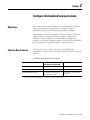
Topics Covered
Chapter 1 Install a ControlNet Communication Module - Shows how
to install and replace a ControlNet communication module on a
PanelView Plus or PanelView Plus CE terminal. Also shows how to
connect module to a ControlNet network.
Chapter 2 Configure Unscheduled Communications - Shows how to
configure ControlNet for Unscheduled messaging between a
PanelView Plus or PanelView Plus CE terminal and an Allen-Bradley
controller.
Chapter 3 Configure Scheduled Communications - Shows how to
configure ControlNet for Scheduled messaging between a PanelView
Plus or PanelView Plus CE terminal and an Allen-Bradley controller.
Chapter 4 Upgrade 2711P-RN15S Firmware - Shows how to upgrade a
2711P-RN15S Series A, Rev. A ControlNet Communications Module to
Rev. C for Scheduled messaging.
Software Requirements
The following software/firmware must be installed on the
development computer and the PanelView Plus or PanelView Plus CE
terminal to configure and communicate with an Allen-Bradley
controller on a ControlNet network.
ControlNet Unscheduled Communications
Software/Firmware
PanelView Plus 700-1500
PanelView Plus CE 700-1500
PanelView Plus 400 or 600
RSView Studio
v3.10 or later
v4.0 or later
RSView Machine Edition Runtime
v3.10 or later
v4.0 or later
ControlNet Module Firmware
2711P-RN15S, Series A, Rev A
(firmware v2.07 or later) (1)
2711P-RN15C, Series A, Rev A
or later
(1)
5
This applies to terminals that are ordered as pre-configured units with the ControlNet module.
Publication 2711P-UM003B-EN-P - March 2007
6
ControlNet Scheduled Communications
Requirements
PanelView Plus 700-1500
PanelView Plus CE 700-1500
PanelView Plus 400 or 600
RSView Studio
v3.20 or later
v4.0 or later
RSView Machine Edition Runtime
v3.20.04.43 or later
v4.0 or later
RSNetWorx for ControlNet
v5.11 or later
v6.0 or later
RSLogix 5000
v13.0 or later
v15.0 or later
ControlNet Module Firmware
2711P-RN15S, Series A, Rev C
(firmware v3.08 or later) (1)
2711P-RN15C, Series A, Rev A
or later
(1)
This applies to terminals that are ordered as pre-configured units with the ControlNet module.
WARNING
Additional Resources
The ControlNet Communications Module (2711P-RN15S) will
not run with RSView ME firmware 3.20.03.43 or earlier. All
ControlNet Modules with v3.07 firmware must be upgraded to
v3.08 or later; otherwise, outputs may turn on an indeterminate
state.
For more information consult the RSView Enterprise or RSView Studio
online help.
Electronic versions of the following publications are available at:
http://www.rockwellautomation.com/literature
•
•
•
•
•
Publication 2711P-UM003B-EN-P - March 2007
PanelView Plus User Manual (2711P-UM001)
PanelView Plus CE User Manual (6182H-UM001)
RSView Machine Edition User Guide (ViewME-UM003)
ControlNet Coax Tap Installation Instructions (1786-IN007)
ControlNet Coax Media Planning and Installation Manual
(CNET-IN002)
Chapter
1
Install a ControlNet Communication Module
Objectives
This chapter shows how to:
• Install and replace a communication module on the PanelView
Plus or PanelView Plus CE terminal.
• Connect the communication module to a ControlNet network.
The communication modules are available as separate catalog
numbers for specific communication protocols.
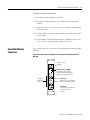
Install Module on 700-1500
Terminals
This section shows how to install a communication module on a
PanelView Plus 700-1500 or PanelView Plus CE 700-1500 devices. The
module installs over the logic module.
TIP
The logic module must be attached to the display
module before you attach the communication
module.
To install a communication module:
1. Disconnect power from the terminal.
WARNING
Do not connect or disconnect any communication
cable with power applied to this device or any
device on the network. An electrical arc could cause
an explosion in hazardous location installations. Be
sure that power is removed or the area is
nonhazardous before proceeding.
2. If the display module is removed from panel, set the module,
display side down, on a clean, flat, stable surface to prevent
scratches.
7
Publication 2711P-UM003B-EN-P - March 2007
8
Install a ControlNet Communication Module
3. Remove the label covering the communication module
connector on the logic module.
Logic Module
REMOVE LABEL TO INSTALL
COMMUNICATION MODULE
4. Position the communication module over the logic module so
that the connectors on bottom of module align with connectors
on logic module.
5. To prevent Electrostatic Discharge (ESD) between the modules,
allow the communication module to touch the logic module
before making connection.
Communication
Module
Connector
Logic Module
6. Push down on communication module until connectors are
firmly seated.
7. Tighten the four screws that secure the communication module
to the logic module. Tighten screws to a torque of 0.68 Nm
(6 to 8 in-lb).
Publication 2711P-UM003B-EN-P - March 2007
Install a ControlNet Communication Module
9
Attached Communication Module
Screw
To replace a communication module:
1. Disconnect power from the terminal.
2. Disconnect communication cables from the communication
module.
3. Remove the four screws that secure the communication module
to the logic module.
4. Carefully lift the communication module away from the logic
module and set aside.
5. Follow steps 4 to 7 in the Install a communication module
procedure.
Install Module on 400-600
Terminals
To install a communication module:
1. Disconnect power from the terminal.
WARNING
If you connect or disconnect any communication
cable with power applied to this module or any
device on the network, an electrical arc can occur.
This could cause an explosion in hazardous location
installations. Be sure that power is removed or the
area is nonhazardous before proceeding.
2. Set the terminal, display side down, on a clean, flat, stable
surface.
Publication 2711P-UM003B-EN-P - March 2007
10
Install a ControlNet Communication Module
3. Remove the label covering the connectors on the base unit of
the terminal.
REMOVE LABEL TO INSTALL
COMMUNICATION MODULE
4. Position the communication module over back of the terminal
so that the connectors on the bottom of communication module
align with the connector on the base unit.
Tighten this
screw first.
Captive
Screws
5. Push down on the communication module until connector is
firmly seated.
6. Tighten the three captive screws that secure the module to the
terminal, starting with the bottom, left screw on the module.
Tighten screws to a torque of 0.34 to 0.45 Nm (3 to 4 in-lb).
Publication 2711P-UM003B-EN-P - March 2007
Install a ControlNet Communication Module
11
To replace a communication module:
1. Disconnect power from the terminal.
2. Disconnect communication cables from the communication
module.
3. Loosen the three screws that secure the communication module
to the terminal.
4. Carefully lift the communication module away from the terminal
and set aside.
5. Install another communication module by following steps 4 to 6
in the Install a communication module procedure.
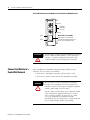
ControlNet Module
Connectors
This section shows the connectors on the ControlNet communication
modules.
2711P-RN15S Communication Module for PanelView Plus/PanelView Plus CE
700-1500
Diagnostic status
indicators
Network Access Port (NAP)
RJ-45 connector for temporarily
connecting programming terminals
to devices on a ControlNet network
Redundant
media BNC
connectors
A
Channel A
Channel B
B
Allen Bradley
ControlNet
Channel A
BNC connectors for connecting
directly to ControlNet network
Channel B
Do not connect more than one
ControlNet network to
this card.
Publication 2711P-UM003B-EN-P - March 2007
12
Install a ControlNet Communication Module
2711P-RN15C Communication Module for PanelView Plus 400/600 Terminals
Channel B
Redundant
media BNC
connectors
Channel A
LED B
LED A
ATTENTION
Connect the Module to a
ControlNet Network
Network Access Port (NAP)
RJ-45 connector for temporarily
connecting programming terminals to
devices on a ControlNet network
Do not connect more than one ControlNet network
to the communication module. If you attempt to
connect a second network to the module, your
communication system will operate erratically.
After installing the ControlNet communication module on the
terminal, you can connect the module:
• Directly to a ControlNet network, which requires a tap
• To a device already connected to the ControlNet network
WARNING
When used in a Class I, Division 2, hazardous
location, this equipment must be mounted in a
suitable enclosure with proper wiring that complies
with the governing electrical codes.
Do not connect or disconnect any communication
cable with power applied to this device or any
device on the network. An electrical arc could
cause an explosion in hazardous location
installations. Be sure that power is removed or the
area is nonhazardous before proceeding.
Publication 2711P-UM003B-EN-P - March 2007
Install a ControlNet Communication Module
13
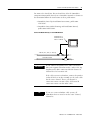
To connect the PanelView Plus or PanelView Plus CE ControlNet
communication module directly to a ControlNet network as shown in
the illustration follow the instructions in these publications:
• ControlNet Coax Tap Installation Instructions, publication
1786-IN007.
• ControlNet Coax Media Planning and Installation Manual,
publication CNET-IN002.
Connect the Module Directly to a ControlNet Network
PanelView Plus or
PanelView Plus CE
with 2711P-RN15S
1786-TPR, -TPS, -TPYR, or -TPYS tap
ControlNet network
IMPORTANT
If you connect the product to a cable system that
does not support redundant media, connect the tap
dropline to the BNC connector labeled Channel A.
Channel B is left unconnected.
If the cable system is redundant, connect the product
so that all devices on the network use the same cable
for the same channel. That is, all Channel A
connectors connect to one cable; all Channel B
connectors connect to the other cable.
TIP
If you use a non-redundant cable system, all
ControlNet devices must be on the same channel,
Channel A.
Publication 2711P-UM003B-EN-P - March 2007
14
Install a ControlNet Communication Module
Publication 2711P-UM003B-EN-P - March 2007
Chapter
2
Configure Unscheduled Communications
Objectives
This chapter shows how to configure a sample ControlNet network
using Unscheduled messaging between a PanelView Plus or
PanelView Plus CE terminal and an Allen-Bradley controller.
Configuring Unscheduled messaging is similar to setting up Ethernet
communications. You do not need to configure settings in the
ControlNet scanner module or use RSNetWorx to configure the
network. Unscheduled communications uses the left over bandwidth
of the ControlNet network to establish its communications.
Software Requirements
Verify that the correct software/firmware is installed on the
development computer and the PanelView Plus or PanelView Plus CE
terminal.
ControlNet Unscheduled Communications
Software/Firmware
PanelView Plus 700-1500
PanelView Plus CE 700-1500
PanelView Plus 400 or 600
RSView Studio
v3.10 or later
v4.0 or later
RSView Machine Edition Runtime
v3.10 or later
v4.0 or later
ControlNet Module Firmware
2711P-RN15S, Series A, Rev A
(firmware v2.07 or later) (1)
2711P-RN15C, Series A, Rev A
or later
(1)
15
This applies to terminals that are ordered as pre-configured units with the ControlNet module.
Publication 2711P-UM003B-EN-P - March 2007
16
Configure Unscheduled Communications
Configure Communications
The procedure in this section shows how to configure a sample
ControlNet network using Unscheduled messaging between a
PanelView Plus/PanelView Plus CE terminal and a ControlLogix
processor. The ControlLogix processor is in Slot 0 and the
1756-CNBR/D ControlNet Scanner Module is in Slot 2 of the chassis.
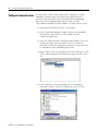
1. Open RSView Studio and create a new project.
2. In the Application Explorer window, double-click on RSLinx
Enterprise to expand the tree. Then double-click on
Communication Setup.
3. Select the Target tab of the communication window. To set the
path for the target, you must add the devices and drivers
manually because the development computer is not connected
by ControlNet to the ControlLogix processor.
4. Right-click on 1789-A17, Backplane and select Add Device. This
is the virtual backplane of the PanelView Plus/PanelView Plus
CE.
5. In the Add Device Selection dialog, select 2711P-RN15S
ControlNet Scanner Card (or 2711P-RN15C) and click OK.
Publication 2711P-UM003B-EN-P - March 2007
Configure Unscheduled Communications
17
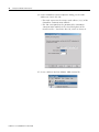
6. In the ControlNet Scanner Properties dialog, set the Node
Address to 2 and click OK.
– The node represents the unique node address (1-99) of the
ControlNet communication module.
– The slot corresponds to the position of the ControlNet
communication module in the virtual backplane of the
PanelView Plus / PanelView Plus CE, which is always 01.
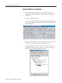
7. Right-click on the ControlNet network type and click Add
Device.
Publication 2711P-UM003B-EN-P - March 2007
18
Configure Unscheduled Communications
8. Right-click on 1756-CNBR/D and select Add Device.
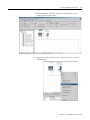
9. In the Device Properties dialog, set the address (or ControlNet
node address) to 1. This is the physical address of the
1756-CNBR/D scanner card.
10. Right-click on the ControlLogix chassis labeled 1756-A17/B and
select Properties.
11. In the Network Properties dialog, set the address of the
1756-A17/B to 2 and click OK. This is the slot in which
1756-CNBR/D is physically located.
12. Right-click on the ControlLogix chassis 1756-A17/B and select
Add Device.
Publication 2711P-UM003B-EN-P - March 2007
Configure Unscheduled Communications
19
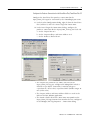
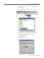
13. Select the ControlLogix processor type that the PanelView Plus /
PanelView Plus CE will communicate with and click OK. For this
example, select 1756-L63.
14. In the Device Properties dialog, set the Address of the processor
to 0, click Apply, and then OK. The address is the slot in which
the processor is physically located.
Publication 2711P-UM003B-EN-P - March 2007
20
Configure Unscheduled Communications
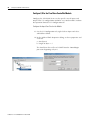
15. Associate a shortcut with the communication path to the
1756-L63 ControlLogix processor.
a. Select 1756-L63 and then click Add.
b. Type the name CNET_UNSCHEDULED and then click Apply.
When finished, the configuration screen looks similar to this.
16. Click OK.
The configuration for ControlNet Unscheduled communications is
complete. You can begin to develop your HMI displays.
Publication 2711P-UM003B-EN-P - March 2007
Chapter
3
Configure Scheduled Communications
Objectives
This chapter shows how to configure a sample ControlNet network
using Scheduled messaging between a PanelView Plus/PanelView
Plus CE terminal and an Allen-Bradley controller. It shows how to:
• Configure the PLC ladder logic file
• Configure the ControlNet network using RSNetWorx for
ControlNet
• Configure the RSView Machine Edition application file
Software Requirements
Verify that the correct software/firmware is installed on the
development desktop and PanelView Plus or PanelView Plus CE
terminal.
ControlNet Scheduled Communications
Requirements
PanelView Plus 700-1500
PanelView Plus CE 700-1500
PanelView Plus 400 or 600
RSView Studio
v3.20 or later
v4.0 or later
RSView Machine Edition Runtime
v3.20.04.43 or later
v4.0 or later
RSNetWorx for ControlNet
v5.11 or later
v6.0 or later
RSLogix 5000
v13.0 or later
v15.0 or later
ControlNet Module Firmware
2711P-RN15S, Series A, Rev C
(firmware v3.08 or later) (1)
2711P-RN15C, Series A, Rev A
or later
(1)
This applies to terminals that are ordered as pre-configured units with the ControlNet module.
ATTENTION
21
The ControlNet Communications Module (2711P-RN15S) will
not run with RSView ME firmware 3.20.03.43 or earlier. All
ControlNet Modules with v3.07 firmware must be upgraded to
v3.08 or later; otherwise, outputs may turn on an indeterminate
state.
Publication 2711P-UM003B-EN-P - March 2007
22
Configure Scheduled Communications
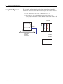
Example Configuration
The example configuration describes how to configure ControlNet
Scheduled communications for a numeric input and numeric output
• from a PanelView Plus with a node address of 2
• to a 1756-L63 v13.0 ControlLogix processor in Slot 0 via
1756-CNB/D ControlNet Scanner Module with a node address of
1 in Slot 2.
ControlNet
Node 1
EtherNet
RSLogix 5000
RSNetWorx
RSView Studio
L
6
3
E
N
B
T
C
N
B
R
ControlNet
ControlNet
Node 2
PanelView Plus
Publication 2711P-UM003B-EN-P - March 2007
Configure Scheduled Communications
Configure PLC Ladder Logic
File
23
To take advantage of ControlNet Scheduled messaging, you need to
configure the PLC ladder logic file so that it knows which tags are
producers and consumers of data from the PanelView Plus /
PanelView Plus CE. These tags are typically configured as Controller
Tags, because a Program Tag cannot be configured as a consumer.
Procedures in this chapter will show how to configure existing DINT
type Controller Tags in a 1756-L63 ControlLogix Processor to be
producers and consumers:
• Output_to_PVP (Producer)
• Input_from_PVP (Consumer)
Publication 2711P-UM003B-EN-P - March 2007
24
Configure Scheduled Communications
Configure the ControlNet Scanner Module
Configure the 1756-CNB/D module.
1. Right-click on I/O Configuration and select New Module.
2. Select 1756-CNB/D and click OK.
3. In the Module Properties dialog, configure the 1756-CNB/D
ControlNet Scanner Module. Enter the name CNBR, select Node
1, select Slot 2, and then click Finish.
Publication 2711P-UM003B-EN-P - March 2007
Configure Scheduled Communications
25
Configure the PanelView Plus ControlNet Module
Configure the 1756-CNB/D module to add a ControlNet PanelView
Plus. This establishes a logical connection between the ControlLogix
processor and the PanelView Plus.
1. Right-click on 1756-CNB/D and select New Module.
2. Select 2711P-RN15S (or 2711P-RN15C) and then click OK.
Publication 2711P-UM003B-EN-P - March 2007
26
Configure Scheduled Communications
3. In the Module Properties dialog, configure the 2711P-RN15S (or
2711P-RN15C) PanelView Plus module. Enter the name PVP,
select Node 2, Revision 7, and then click Finish.
Configure the Controller Tags
Configure these Controller tags as consumer and producer:
• Input_From_PVP = consumed tag type
• Output-From_PVP = produced tag type
Configure the Consumer Tag
1. Right-click on the Input_From_PVP tag and select Edit Tag
Properties.
Publication 2711P-UM003B-EN-P - March 2007
Configure Scheduled Communications
27
2. In the Tag Properties dialog, configure the Input_From_PVP tag
with the Tag Type=Consumed and Data Type=DINT. The
processor will be a consumer of data from the PanelView Plus.
3. On the Connections tab, configure the connection properties of
this consumed tag so that the device producing the data is PVP,
the Remote Data value is 1, and the Request Packet Interval
(RPI) is 20 ms. When finished, click OK.
• The Remote Data value is a connection ID that must correspond
to the PVP producer connections configured in RSNetWorx.
• The Requested Packet Interval (RPI) value is determined by how
often you want a particular piece of I/O or Scheduled
peer-to-peer data to be transmitted within the Scheduled
bandwidth of the Network Update Interval.
Publication 2711P-UM003B-EN-P - March 2007
28
Configure Scheduled Communications
Configure the Producer Tag
Configure the Output_to_PVP tag to be a producer of data to the
PanelView Plus.
1. Select the check box in the P column next to the tag name
Output_to_PVP.
2. Right-click on the checked Output_to_PVP tag and select Edit
Tag Properties.
Publication 2711P-UM003B-EN-P - March 2007
Configure Scheduled Communications
29
3. In the Tag Properties dialog, configure the Output_To_PVP tag
with the Tag Type=Produced and Data Type=DINT.
4. On the Connection tab, set the number of Maximum Consumers
to 1 and click OK.
If this specific data is going to be consumed by many PanelView
Plus terminals, enter the number of terminals that would be
receiving this data.
5. Save the ladder logic program, download the ladder to the
ControlLogix processor, and put the processor in Run mode.
The ControlLogix processor is configured and ready to produce and
consume data from the PanelView Plus. Next, configure the
ControlNet network using RSNetWorx for ControlNet.
Publication 2711P-UM003B-EN-P - March 2007
30
Configure Scheduled Communications
Configure ControlNet With
RSNetWorx
Use the RSNetWorx software to configure the ControlNet Scanner
Module to read and write Scheduled data from the PanelView Plus to
the Allen-Bradley controller. This is accomplished in two steps:
• Configure the communication module
• Configure RSNetWorx for ControlNet
Chapter 4 describes how to upgrade a 2711P-RN15S Series A, Rev. A
communication module to Rev. C for Scheduled messaging.
Configure the Communication Module
When a new 2711P-RN15S (or 2711P-RN15C) ControlNet
communication module is installed in a PanelView Plus or PanelView
Plus CE, the terminal requires some basic settings to establish
communications with the ControlNet communication card.
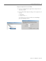
1. Create a new RSLinx Enterprise communication configuration by
double-clicking on Communication Setup, select Create a new
configuration, and click Finish.
2. Click on the Target tab of the communication window. To set
the path for the target, the devices and drivers must be added
manually because the development computer is not connected
by ControlNet to the ControlLogix processor.
Publication 2711P-UM003B-EN-P - March 2007
Configure Scheduled Communications
31
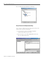
3. Right-click on 1789-A17, Backplane and select Add Device. This
is the virtual backplane of the PanelView Plus/PanelView Plus
CE.
4. In the Add Device Selection window, select 2711P-RN15S
ControlNet Scanner Card (or 2711P-RN15C) and click OK.
Publication 2711P-UM003B-EN-P - March 2007
32
Configure Scheduled Communications
5. In the ControlNet Scanner Properties dialog, set the Node
Address to 2 and click OK.
– The node represents the unique node address (1-99) of the
ControlNet communication module.
– The slot corresponds to the position of the ControlNet
communication module in the virtual backplane of the
PanelView Plus / PanelView Plus CE, which is always 01.
6. Create a RSView Machine Edition .MER runtime file.
Publication 2711P-UM003B-EN-P - March 2007
Configure Scheduled Communications
33
7. Download the .MER file to the terminal, and run the project. If
successful, the communication status LEDs will light on the
2711P-RN15x module.
8. A sample .MER has been created to configure the 2711P-RN15x
as Node 2 on a ControlNet network.
This application is located in Technote A103053983 on the
Rockwell Automation Technical Support Knowledgebase at
http://support.rockwellautomation.com. Download and run the
ControlNet Configuration.mer runtime file on the PanelView
Plus or PanelView Plus CE.
9. Press the Goto Configure button to return to the RSView ME
configuration menu.
You are now ready to configure RSNetWorx for ControlNet for
communications with the 2711P-RN15x ControlNet Module.
Publication 2711P-UM003B-EN-P - March 2007
34
Configure Scheduled Communications
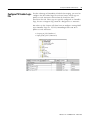
Configure RSNetworx for ControlNet
1. Open RSNetWorx for ControlNet by selecting Start Menu >
Programs > Rockwell Software > RSNetWorx > RSNetWorx for
ControlNet
2. Select the Enable Edits box.
If you are using RSNetWorx for ControlNet with RSLogix 5000,
select enable edits to import the external connection information
from RSLogix 5000.
3. Browse the ControlNet network to find the devices that need to
be configured. Select the icon or Network > Online.
If the configuration computer is not connected directly to the
ControlNet network, you can gain access to the network via
Ethernet to a 1756-ENBT module as shown.
Publication 2711P-UM003B-EN-P - March 2007
Configure Scheduled Communications
35
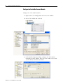
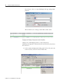
4. After RSNetWorx identifies all of the available devices, the
display looks similar to this:
5. Right-click on the PanelView Plus System and select Scanlist
Configuration.
Publication 2711P-UM003B-EN-P - March 2007
36
Configure Scheduled Communications
The Scanlist Configuration dialog opens and looks similar to
screen below. This screen is used to set up the network
Scheduling. This involves creating producer connections relative
to each network device.
Publication 2711P-UM003B-EN-P - March 2007
Configure Scheduled Communications
37
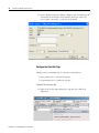
Configure the Producer Connection for the PanelView Plus/PanelView Plus CE
Configure the PanelView Plus producer connection for the
Input_From_PVP tag to be consumed by the ControlLogix processor.
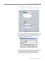
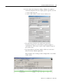
1. In the Scanlist Configuration dialog, right-click on the PanelView
Plus (address 2) and select Insert Target for Connections.
2. In the Insert Target for Connections dialog, configure the
producer connection for the Input_From_PVP tag and click OK.
a. Set the Output Size to 2.
b. Set the Output Address and Status Address to 0.
c. Set the Producer Buffer ID to 1.
PV Plus CE ControlNet - Scanlist Configura
• The Output Size parameter (in words) must match the
Input_From_PVP tag size configured in RSLogix5000 which is
defined as type DINT. Two words (a word or integer is
equivalent to a 16-bit value) equal one DINT (double integer or
one 32-bit value).
• The Output Address and Status Address fields are used in the
RSView Machine Edition application.
• The Produce Buffer ID of this connection corresponds to the
Input_From_PVP tag’s Remote Data number that was configured
in the RSLogix 5000 Tag Properties \ Connection dialog.
Publication 2711P-UM003B-EN-P - March 2007
38
Configure Scheduled Communications
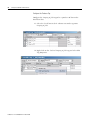
For reference, here is a copy of RSLogix 5000 tag configuration
property.
When finished, the resulting scanlist looks similar to this:
Configure the Producer Connection for the Controller
Configure the ControlLogix producer connection for the
Output_to_PVP tag to be consumed by the PanelView Plus/PanelView
Plus CE device.
1. In the Scanlist Configuration dialog, right-click on the processor
named 1756-L63 and select Insert Connection.
PV Plus CE ControlNet - Scanlist Configuration
Publication 2711P-UM003B-EN-P - March 2007
Configure Scheduled Communications
39
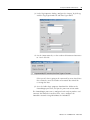
2. In the Connection Properties dialog, configure the producer
connection properties for the Output_to_PVP tag and click OK.
a. Set the Input Size to 2.
b. Set the Input Address and the Status Address to 0.
• The Input Size parameter (in words) must match the
Output_to_PVP tag size. Two words (a word or integer is
equivalent to a 16-bit value) equal 1 DINT (double integer or
one 32-bit value).
• The Input Address and Status Address fields are used in the
RSView Machine Edition application.
When finished, the resulting scanlist configuration screen looks
similar to this:
PV Plus CE ControlNet - Scanlist Configuration
Publication 2711P-UM003B-EN-P - March 2007
40
Configure Scheduled Communications
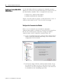
Save and Download the Scanner Configuration
Save and download the scanner configuration to the ControlNet
scanner.
1. Select the File Save icon or File>Save from the menu.
PV Plus CE ControlNet - Scanlist Configuration
A dialog prompts you to select the type of save configuration.
2. Select Optimize and re-write schedule for all connections and
click OK.
3. Save the configuration file as ControlNet.xc.
Publication 2711P-UM003B-EN-P - March 2007
Configure Scheduled Communications
41
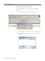
4. When the download is complete, select the Connection Status
tab. It should look similar to this:
PanelView Plus CE ControlNet - Scanlist Configuration
All of the ControlNet scanners have been successfully configured. The
final step to begin ControlNet Scheduled communications is to
configure the RSView Machine Edition project.
Configure the RSView
Machine Edition
Application
Now that the ControlLogix processor and the ControlNet network are
configured, the last item to configure for ControlNet Scheduled
communications is the RSView Machine Edition application. Follow
the procedures in this section to configure an RSView Machine Edition
application.
ATTENTION
ControlNet Scheduled Communications is not supported during
runtime for the desktop version of RSView Machine Edition.
Publication 2711P-UM003B-EN-P - March 2007
42
Configure Scheduled Communications
Create a New Configuration
1. Start RSView Studio and create a new application named
ControlNet Messaging.
2. Create a new RSLinx Enterprise communication configuration.
Double-click on Communication Setup, select Create a new
configuration, and click Finish.
Publication 2711P-UM003B-EN-P - March 2007
Configure Scheduled Communications
43
3. From the Local tab, right click on 1789-A17, Backplane and
select Add Device.
4. Select 2711P-RN15S (or 2711P-RN15C) and click OK.
5. In the ControlNet Scanner Properties dialog, configure the
2711P-RN15x communication module and click OK.
a. Name = ControlNet Scanner Card for PanelView
Plus/PanelView Plus CE
b. Node Address = 02
c. Slot in Virtual Backplane = 01.
Publication 2711P-UM003B-EN-P - March 2007
44
Configure Scheduled Communications
Configure I/O for the PanelView ControlNet Module
Configure the 2711P-RN15x to scan the specific size of inputs and
output. This I/O configuration method is very similar to RIO. Perform
this operation from the I/O Configuration tab.
Configure the Input Scan Size for the Module
1. On the I/O Configuration tab, right-click on Input and select
Add Address Block.
2. In the Address Block Properties dialog, set these properties and
click OK.
a. Start Byte=0
b. Length in Bytes = 4
The PanelView Plus will read 1 DINT from the ControlLogix
processor beginning at byte 0.
Publication 2711P-UM003B-EN-P - March 2007
Configure Scheduled Communications
45
Configure the Input Connection
1. Under Inputs, right click on 0-3 Bytes and select Add
Connection.
2. In the Connection Properties dialog, set these properties and
click OK.
a. Start Byte = 0
b. Length in Bytes = 4
c. Status Address = 2
d. Node (MAC ID) = 1
e. Slot = 0
The PanelView Plus will read 1 DINT from a ControlLogix
processor located in slot 0 via a ControlNet scanner module
addressed at node 1, and the Status Address is assigned by
RSNetWorx for ControlNet.
Publication 2711P-UM003B-EN-P - March 2007
46
Configure Scheduled Communications
Identify Where the Input Data is Coming From
Identify where the raw input data is coming from by creating an Alias
to allow RSView Machine Edition to use this data.
1. Right-click on 0-3 Bytes under Input and select Add Alias.
2. In the Alias Properties Dialog, select the Alias Data Type DINT,
set these properties, and then click OK.
a. Alias Name = Input
b. Start Byte = 0
c. Array Count = 1
d. and specify the address.
Publication 2711P-UM003B-EN-P - March 2007
Configure Scheduled Communications
47
Configure the Output Scan Size for the Module
1. On the I/O Configuration tab, right-click on Output and select
Add Address Block.
2. In the Address Block Properties dialog, set these properties and
click OK.
a. Start Byte=0
b. Length in Bytes = 4
The PanelView Plus will send 1 DINT to the ControlLogix
processor beginning at byte 0.
Publication 2711P-UM003B-EN-P - March 2007
48
Configure Scheduled Communications
Configure the Output Connection
1. Under Outputs, right click on 0-3 Bytes and select Add
Connection.
2. In the Connection Properties dialog, set these properties and
click OK.
a. Start Byte = 0
b. Length in Bytes = 4
c. Status Address = 2
d. Node (MAC ID) = 1
e. Slot = 0
The PanelView Plus will send 1 DINT to the ControlLogix processor
located in slot 0 via a ControlNet scanner module addressed at node
1. The Status Address is assigned by RSNetWorx for ControlNet.
Publication 2711P-UM003B-EN-P - March 2007
Configure Scheduled Communications
49
Identify Where the Output Data is Going
Identify where the raw output data is going by creating an Alias to
allow RSView Machine Edition to use this data.
1. Right-click on 0-3 Bytes under Output and select Add Alias.
2. In the Alias Properties Dialog, select the Alias Data Type DINT,
set these properties, and click OK.
a. Alias Name = Output
b. Start Byte = 0
c. Array Count = 1
The PanelView will send these 4 bytes as a DINT to the
ControlLogix processor.
Publication 2711P-UM003B-EN-P - March 2007
50
Configure Scheduled Communications
The I/O configuration should look like the following:
Create a Shortcut to the Communication Setup
Create a shortcut in both the Local and Target tabs to reference this
communication setup for the HMI display.
1. On the Local tab, select the 2711P-RN15x ControlNet
communication module and select Add.
2. Enter the shortcut name CNET_SCHEDULED and click OK.
The screen looks similar to this.
Publication 2711P-UM003B-EN-P - March 2007
Configure Scheduled Communications
51
3. Configure the same shortcut for the Target tab.
A simple way to do this is by selecting Copy. This copies the
configuration of the Local tab to the Target tab.
4. Verify that no devices are configured for Ethernet
communications in the Target tab. If devices exist for Ethernet
communications in the Target tab, delete the devices but keep
the Ethernet driver.
5. Click OK when done.
ControlNet Scheduled communications is now configured. Develop
the rest of the RSView Machine Edition application using this
communication configuration. A sample ControlNet Scheduled
communication application is available on the Rockwell Automation
Technical Support Knowledgebase in Technote A103053983 at
http://support.rockwellautomation.com.
Address Assignments for Objects
Tag addresses are assigned to objects in the Tag Browser.
To access the Tag Browser:
1. Select an object and then select the Connections tab. To do this,
either:
• right-click on object and select Connections
• double-click to open the object’s Properties dialog and select
the Connections tab.
2. Click on tag to open the Tag Browser.
3. Open the path to the CNET_SCHEDULED tags.
The folder is <application name><shortcut>Online and either
Input Table or Output Table.
The Input Table folder is used for input data received by the
PanelView Plus/PanelView Plus CE device from another device.
The Output Table folder is used for output data that is sent from
the PanelView Plus/PanelView Plus CE device to another device.
Publication 2711P-UM003B-EN-P - March 2007
52
Configure Scheduled Communications
The syntax for the selected tag appears in the Selected Tag area.
For example, {[CNET_SCHEDULED]InputTable.Input}
"CNET_SCHEDULED" => Shortcut name
"InputTable"=> Table name
"Input"=> Alias name
Publication 2711P-UM003B-EN-P - March 2007
Chapter
4
Upgrade a 2711P-RN15S Module Firmware
Objectives
This chapter shows how to upgrade the firmware for a 2711P-RN15S
Series A, Rev. A ControlNet Communications Module to Rev. C for
Scheduled messaging. This also applies to terminals pre-configured
and shipped from the factory with a ControlNet Module. During the
upgrade, the module firmware is updated from v2.7 to v3.8 or later.
The firmware upgrade is available at the Rockwell Automation
Technical Support website under Firmware Updates and RSView ME.
All 2711P-RN15C ControlNet communication modules for PanelView
Plus 400 and 600 support ControlNet Scheduled Messaging.
PanelView Plus CE (FUW utility)
53
Publication 2711P-UM003B-EN-P - March 2007
54
Upgrade a 2711P-RN15S Module Firmware
Configure the
Communication Module
When a new 2711P-RN15S communication module is installed in a
PanelView Plus or PanelView Plus CE, the terminal requires some
basic settings to establish communications.
1. Create a new RSLinx Enterprise communication configuration by
double-clicking on Communication Setup, select Create a new
configuration, and click Finish.
2. Click on the Target tab of the communication window.
To set the path for the target, the devices and drivers must be
added manually because the development computer is not
connected by ControlNet to the ControlLogix processor.
3. Right-click on the virtual backplane of the PanelView Plus /
PanelView Plus CE labeled 1789-A17, Backplane, and select Add
Device.
Publication 2711P-UM003B-EN-P - March 2007
Upgrade a 2711P-RN15S Module Firmware
55
4. In the Add Device Selection dialog, select 2711P-RN15S,
ControlNet Scanner Card for and click OK.
5. In the ControlNet Scanner Properties dialog, set the Node
Address to 2 and click OK.
– The node represents the unique node address (1-99) of the
ControlNet Communication Module.
– The slot corresponds to the position of the ControlNet
communication module in the virtual backplane of the
PanelView Plus / PanelView Plus CE, which is always 01.
Publication 2711P-UM003B-EN-P - March 2007
56
Upgrade a 2711P-RN15S Module Firmware
6. From the Application menu, choose Create Runtime Application
to create an RSView Machine Edition runtime file.
7. Compile the project, download it to the terminal, and run the
project. If successful, the communication status LED’s illuminate
on the 2711P-RN15S module.
A sample .MER has been created to configure the 2711P-RN15S
as Node 2 on a ControlNet network. This application is located
on Technote A103053983 on the Rockwell Automation Technical
Support Knowledgebase at
http://support.rockwellautomation.com. Download and run
ControlNet Configuration.mer on the PanelView Plus or
PanelView Plus CE.
Publication 2711P-UM003B-EN-P - March 2007
Upgrade a 2711P-RN15S Module Firmware
57
8. Click the Goto Configure button to return to the RSView ME
configuration menu.
You can now upgrade the firmware in the 2711P-RN15S
ControlNet module to v3.8 or later.
Upgrade the ControlNet
Module Firmware to v3.8 or
later
After the 2711P-RN15S Series A, Revision A module is initially
configured, you must upgrade the module firmware to v3.8 or later to
support ControlNet Scheduled messaging.
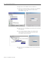
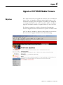
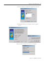
1. Start the ControlFlash firmware upgrade utility and click Next.
2. Select 2711P-RN15S and click Next.
Publication 2711P-UM003B-EN-P - March 2007
58
Upgrade a 2711P-RN15S Module Firmware
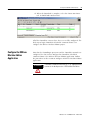
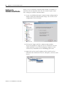
3. Select 2711P-RN15S to upgrade via an Ethernet or ControlNet
network and click OK.
02, PV Plus/PV Plus CE ControlNet, 2711P-RN1...
01, PV Plus/PV Plus CE ControlNet, 2711P-RN1...
Publication 2711P-UM003B-EN-P - March 2007
Upgrade a 2711P-RN15S Module Firmware
59
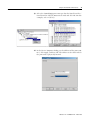
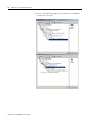
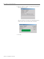
4. Select the firmware revision for the upgrade and click Next.
3.8
5. Click Finish and then Yes to begin the firmware upgrade
process.
3.8
Communications will begin and the firmware will update.
3.8
Publication 2711P-UM003B-EN-P - March 2007
60
Upgrade a 2711P-RN15S Module Firmware
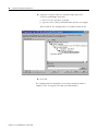
6. When the upgrade is complete, cycle power on the PanelView
Plus or PanelView Plus CE.
3.8
When the terminal recycles power, the Control Flash firmware
upgrade utility verifies the communication card update.
3.8
3.8
7. Click OK.
Publication 2711P-UM003B-EN-P - March 2007
Upgrade a 2711P-RN15S Module Firmware
61
Publication 2711P-UM003B-EN-P - March 2007
62
Upgrade a 2711P-RN15S Module Firmware
Publication 2711P-UM003B-EN-P - March 2007
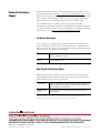
Rockwell Automation
Support
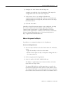
Rockwell Automation provides technical information on the Web to assist
you in using its products. At http://support.rockwellautomation.com, you can
find technical manuals, a knowledge base of FAQs, technical and application
notes, sample code and links to software service packs, and a MySupport
feature that you can customize to make the best use of these tools.
For an additional level of technical phone support for installation,
configuration, and troubleshooting, we offer TechConnect Support programs.
For more information, contact your local distributor or Rockwell Automation
representative, or visit http://support.rockwellautomation.com.
Installation Assistance
If you experience a problem with a hardware module within the first 24
hours of installation, please review the information that's contained in this
manual. You can also contact a special Customer Support number for initial
help in getting your module up and running.
United States
1.440.646.3223
Monday – Friday, 8am – 5pm EST
Outside United
States
Please contact your local Rockwell Automation representative for any
technical support issues.
New Product Satisfaction Return
Rockwell tests all of its products to ensure that they are fully operational
when shipped from the manufacturing facility. However, if your product is
not functioning, it may need to be returned.
United States
Contact your distributor. You must provide a Customer Support case
number (see phone number above to obtain one) to your distributor in
order to complete the return process.
Outside United
States
Please contact your local Rockwell Automation representative for
return procedure.
Allen-Bradley, Rockwell Automation, TechConnect, and VersaView are trademarks of Rockwell Automation, Inc.
Trademarks not belonging to Rockwell Automation are property of their respective companies.
Publication 2711P-UM003B-EN-P - March 2007 64
Supersedes Publication 2711P-UM003A-EN-P - August 2005
Copyright © 2007 Rockwell Automation, Inc. All rights reserved. Printed in the U.S.A.