1
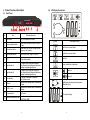
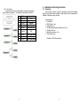
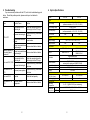
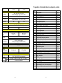
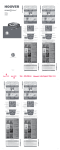
Table of Contents 1. 2. 3. 3.1. 3.2. 3.3. 3.4. 4. 4.1. 4.2. 4.3. 5. 6. 7. Important Safety Instructions................................................................. 2 Overview ............................................................................................... 3 Product Functional Description ............................................................. 4 Front Panel............................................................................................ 4 LCD Display Description ....................................................................... 5 Rear Panel ............................................................................................ 6 Communication Interface ...................................................................... 7 Installation and Operating Instructions .................................................. 9 Unpacking ............................................................................................. 9 Installation Procedures........................................................................ 10 Operating Procedures ......................................................................... 11 Troubleshooting .................................................................................. 12 System Specifications ......................................................................... 13 Appendix A. Customized features to configure dry contacts ............... 15 Automatic Transfer Switch User Manual ATS-16A/20A/30A/32A 1 1. Important Safety Instructions 2. Overview This document provides important instructions for a safe installation, operation and use of the ATS. The ATS (Automatic Transfer Switch) features two independent power supply source supplying power to the load (as shown in Figure 1 below). In the event of a power failure in the main utility (Source A), the ATS automatically switches to Source B to supply power to the load. The ATS automatically switches back to Source A after power is restored. In addition, the ATS provides user configurable power status (voltage or frequency) for the ATS switching condition. 1. Do not disassemble the ATS as there are no serviceable parts inside. Disassembling can cause electric shock and warranty will be void. 2. All repairs and maintenance should only be done by a qualified technician or authorized distributor. 3. This ATS supports electronic equipment in office, telecommunication, process control, medical and security applications. Non-authorized technicians are not allowed to install the ATS in the following areas: a. Life supporting medical equipment. b. Elevators, subway systems or any other equipment related to human safety. c. Public systems critical computer systems. 4. Please discuss with your distributor before installing the product at the locations mentioned above. Special considerations and designs are required for the operation, setup, management, and maintenance of critical equipment and emergency backup power generators related to personal safety and public facilities. 5. This equipment is not water proof. 6. Do not install the ATS in an environment with sparks, smoke, or gas. 7. This ATS is designed to be installed in a sheltered, controlled environment as follow: - Operating temperature 0-40°C, and 30-90% non-condensing humidity; - Avoid locations with dust, corrosive material, salt content, or flammable gas; - Install the ATS indoors as it is not designed for outdoor installation. 8. Improper grounding results in electrical leakage. Please ensure your AC input power is properly grounded. 9. Ensure the input voltage of the ATS matches the utility supply voltage. Use a certified input power cable with the correct plugs and sockets for the appropriate voltage system. 2 SOURCE A Load SOURCE B Figure 1. ATS block diagram 3 3.2. LCD Display Description 3. Product Functional Description 3.1. Front Panel No. 1 ○ 2 ○ 3 ○ 4 ○ 5 ○ Item Mute button Source selection button Info selection button Select source to view info: Input A, Input B, or Load Select source info to view: Voltage, current, frequency, load capacity Switch input source: Input A Input B LCD System status display Input indicator A 7 ○ Input indicator B ○ 9 ○ 10 ○ 11 ○ 12 ○ Turn off the sound of the alarm Input selection button 6 ○ 8 Description/function Error indicator USB port RS-232 port Dry contact port Lit: Normal input voltage and frequency Dim: Abnormal input voltage and frequency Flashing: Indicates higher priority Lit: Normal input voltage and frequency Dim: Abnormal input voltage and frequency Flashing: Indicates higher priority Lit: System malfunction or abnormal Dim: System normal Connection for software setup or monitoring software Connection for software setup or monitoring software Dry Contact Symbol Description/function Input A error or power failure Input B error or power failure Overload System malfunction or abnormal Alarm on Alarm off Digital display showing input/output power connected to load ATS numeric display For external communication cards, External communication slot e.g. RS-485, SNMP 4 5 3.3. Rear Panel 3.4. Communication Interface Following is a rear view and basic information for each available ATS model. ATS-216 (230V-16A) The ATS provides three communication ports and one external communication slot (optional) for the user. Standard communication ports: RS-232, USB, and 5 dry contacts External communication slot: SNMP, RS-485 3.4.1. RS-232 ATS-120 (120V-20A) ATS- 232 (230V-30A) 3.4.2. Pin 1 2 3 4 Definition N/A TX RX N/A 5 GND 6 +12V 7 8 9 N/A N/A N/A Type N/A Output Input N/A Power source Power source N/A N/A N/A Signal N/A TX RX N/A N/A N/A N/A N/A N/A USB Pin Signal 1 VBUS 2 D- 3 D+ 4 GND ATS- 130(120V-30A) 1 Power input (B) 5 Output socket ○ ○ 2 Power input (A) 6 Output breaker ○ ○ 3 ,○ 4 Input breaker (optional, sold separately) ○ 6 7 3.4.3. Dry Contact The ATS provides five user configurable dry contacts for customized features (Refer to Appendix 1). The capacity of each contact is 24Vdc/1A. Pin 1 2 3 4 5 Definition Common 3 Relay 3 Relay 4 Common Relay 5 Signal (default) N/A System Alarm Overload N/A Over temperature 6 Common 1 N/A 7 8 9 Relay 1 Common 2 Relay 2 Source A abnormal N/A Source B abnormal 8 4. Installation and Operating Instructions 4.1. Unpacking Upon receiving of goods, inspect the package and contents for shipping damage. Any missing contents, damage or other problem must be reported to the forwarder or dealer as soon as possible. Product Inventory: ATS Module RS-232 cable x1 pcs USB cable x1 pcs CD (Monitoring software and Setting tool) x1 pcs User Manual x1 pcs Backplate and screws x1 set *Power cable x2 pcs *Available for ATS-216 models only. 9 4.2. Installation Procedures 4.3. Operating Procedures 1. Affix the two included backplates to the ATS as shown in Figure 1. 2. Mount the ATS into a 19” rack or into a cabinet with 19” inner design as shown 4.3.1. Boot Up Once the input power is connected, the ATS automatically boots up and the LCD on Figure 2. display and LEDs ( 3. Connect the load power cords to the ATS sockets labelled "OUTPUT" the LCD display the input source voltage as shown in Figure 4 and the selected 4. Check that the total load does not exceed ATS specifications (e.g. voltage, Input indicator A ( , , ) are lit as shown in Figure 3. After boot up, ) LED or Input indicator B ( ) LED is lit. current). 5. Turn on all connected equipment. The ATS automatically boots up after 1 second and supply power to the connected load. Figure 3 4.3.2. Figure 4 Switch input source Figure 1 The ATS supports manual switching between power supplies as instructed below: Press and hold the Input selection button for 2 seconds until you hear two short beeps. The system display the power transfer (LCD display as shown in Figure 5), press again and hold the Input selection button for 2 seconds to confirm. The system will switch to Source B (LCD display as shown in Figure 6) if the power supply is present. the LCD display a warning If the power supply is not present and switching fails, as shown in Figure 7. Figure 2 Figure 5 10 Figure 6 11 Figure 7 5. Troubleshooting 6. System Specifications If you are encounter problems with the ATS, refer to the troubleshooting guide below. Should the problem persists, please contact your local dealer for assistance. Model ATS-120 ATS-130 Input Issue ATS is OFF Power is supplied to the load but panel remains off Possible Cause Solution Input voltage Not connected to the electrical grid Check the connection from the electrical grid to the ATS input Input voltage range Abnormal electrical grid Request service by professional electrician Reset breaker Output voltage Output current Internal components have Please contact the local dealer. been damaged Connection Internal components have Please contact the local dealer been damaged Output Check the connection from the electrical grid to the ATS input Abnormal electrical grid Request service by professional electrician Error code Er03 to Er15 Abnormal power system Request service by professional electrician Error code Er16 Overload Check the load capacity Error code Er17 to Er32 Input current Output Input breaker has been tripped Not connected to the electrical grid Error code Er01, Er02 Input frequency 100V / 110V / 115V / 120V / 127V (software selectable: +/-5%, 10%, 15%, 20%) 75Vac~150Vac 50/60Hz (software selectable: +/- 5%, 10%, 15%, 20%) 20A 30A Abnormal internal components 12 Please contact the local dealer Input Protection Communication Transfer time(ms) Efficiency Display Physical Dimension, D X W X H (mm) Net Weight (kgs) Environment Operating temperature Safety Standards compliance EMC 100V / 110V / 115V / 120V / 127V 20A 30A NEMA 5-20 x 2 NEMA L5-30 x 2 NEMA 5-20 x 16, NEMA 5-20 x 8 NEMA L5-30 x 1 Input Breaker(option) Electronic circuit RS-232, USB, Dry contact external slot for option card (SNMP, RS-485) 6ms typical, 16ms maximum 99% (with full linear load) LCD+LED 275 x 440 x 44 275 x 440 x 88 4 6 -5~40∘C @ 20~90% RH (non-condensing) UL 60950-1/CAN/CSA C22.2 No. 60950-1 FCC Part 15 13 7. Appendix A. Customized features to configure dry contacts Model ATS-216 ATS-232 Input Input voltage Input voltage range Input frequency Input current 200V / 208V / 220V / 230V / 240V (software selectable: +/- 5%, 10%, 15%, 20%) 150Vac~300Vac 50/60Hz (software selectable: +/- 5%, 10%, 15%, 20%) 16A 32A Output Output voltage Output current 200V / 208V / 220V / 230V / 240V 16A 32A Connection Input output Protection Communication Transfer time(ms) Efficiency Display Physical Dimension, D X W X H (mm) Net Weight (kgs) Environment Operating temperature Standards Safety compliance EMC IEC-C20 inlets x2 40A terminal 6P IEC-C13 x 8, IEC-C13 x16, IEC-C19 x 1 IEC-C19 x2 Input Breaker (option) Electronic circuit RS-232, USB, Dry contact external slot for option card (SNMP, RS-485) 6ms typical, 16ms maximum 99% (with full linear load) LCD+LED 275 x 440 x 44 275 x 440 x 88 4 6 -5~40∘C @ 20~90% RH (non-condensing) UL 60950-1/ CAN/CSA C22.2 No. 60950-1 , IEC 60950-1 FCC Part 15 , EN62310-2 14 1 2 3 4 5 6 7 8 9 10 11 12 13 14 15 16 17 18 19 20 21 22 23 24 25 26 27 28 29 30 31 32 Event Source A no power Source B no power Source A voltage abnormal Source B voltage abnormal Source A frequency abnormal Source B frequency abnormal Source A voltage and frequency abnormal Source B voltage and frequency abnormal ATS no output due to source A and B abnormal Source A voltage unbalance Source B voltage unbalance ATS output voltage unbalance ATS output voltage abnormal ATS output frequency abnormal ATS output voltage and frequency abnormal ATS output overload and cut output ATS output short circuit and cut output Input relay defect on source A Input relay defect on source B Source transfer relay defect ATS output relay defect Internal working power 12V defect on source A Internal working power 12V defect on source B System over temperature System DC offset error EEPROM working abnormal Emergency Power Off Loss LCD connection Internal transferring inhibition by some reason Overload transferring is over 4 times and system lock Inhibit to transferring due to phase angle over shift System Alarm 15 Code Er01 Er02 Er03 Er04 Er05 Er06 Er07 Er08 Er09 Er10 Er11 Er12 Er13 Er14 Er15 Er16 Er17 Er18 Er19 Er20 Er21 Er22 Er23 Er24 Er25 Er26 Er27 Er28 Er29 Er30 Er31 Er32 16 17 19232 18