1
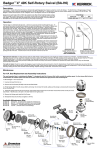
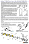
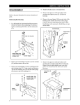
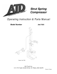
BADGER 4” 40K
SELF-ROTARY SWIVEL (BA-H6)
USER MANUAL
PL-600 (09/2014)
OVERVIEW
DESCRIPTION:
The Badger™ Rotary Waterblast Nozzle was designed for
waterblast cleaning of pipes as small as 4 inch with elbows.
The BA-H6 has a 3/8 high pressure female inlet connection
and a maximum operating pressure of 43,500 psi (3000 bar).
A viscous fluid is used to control rotation speed in the range of
200 to 500 rpm. The Badger™ heads have five S6 ports; one
at 15 degrees, two at 100 degrees, and two at 125 degrees
Engraved on each head is R14 or R24; this number is the offset
of the head that makes it rotate. The flow range for each head
is given in the table; nozzle sizes must be selected to fit within
this flow range. If the flow is less than the range shown, the tool
will not rotate; if it is more than the range maximum, the tool will
rotate too fast and wear out the seals and bearings prematurely.
FLOW RANGE
PRESS. PSI
R50
R35
R25
43,500 (3000 BAR)
4.5-7 GPM
7-9.5 GPM
9.5-12 GPM
The Badger should begin to slowly rotate. Once operating
pressure is reached, feed the tool into the pipe to begin the
cleaning job. Allow the jets time to do their work by feeding the
hose out at a controlled rate. The StoneAge ABX-500 Hose
Control Device can be used to achieve consistant feed rates
for pipe cleaning. When the work is complete and the tool is
isconnected from the hose, blow out all water to prolong the life
of the tool. A small amount of oil can be blown into the tool as
well as an added measure to maximize tool life.
WARNING
Operations with this equipment can be potentially
hazardous. Caution must be exercised prior to and
during machine and water jet tool use. Please read
and follow all of these instructions, in addition to
the guidelines in the WJTA Recommended Practices
handbook, available online at www.wjta.org. Deviating
from safety instructions and recommended practices
can lead to severe injury and/or death.
FIGURE 1
OPERATION:
The first step is to determine the jet sizes. Jet thrust is used to
pull the tool through the pipe. An estimate of the amount of
pulling force required is useful and depends on the number
of elbows and any vertical climbs that must be made. On
a horizontal run with no elbows, roughly 1 pound of pull is
required for every ten feet. When climbing vertically, the pulling
force must equal the weight of the tool and the hose. Typically,
larger jet sizes using 40-60% of the total flow are used in the
back 125° ports. As little as 10% of the total flow is given to
the front jet, because it pushes the wrong direction and is only
used to open up blockages. The remaining flow goes to the
100° ports, which do help pull as well, but are mor fuctional
for pipe cleaning. Nozzles selected should be matched pairs,
except the front jet. When installing nozzles, we recommend
using Blue Goop® antisieze.
1-1/2 times
pipe ID
Rigid
Stinger
WARNING
Because of the short length of the Badger, the tool can turn
around in large pipes and come back at the operator at a high
rate of speed. If cleaning larger pipes, a rigid “stinger” should
be used between the hose and the tool. It is recommended
that the rigid length of the tool including hose end is 1-1/2 times
the inside diameter of the pipe being cleaned (see Figure 1).
IMPROPER USE:
Badger will turn around in
large diameter pipe
VERY DANGEROUS!
Make sure there is an operator controlled dump in the system,
operated by the person closest to the cleaning job. Flush out
the high pressure hoses before connecting the Badger. It is
recommended that the hose be marked a few feet from the
end with a piece of tape so the operator knows when to stop
when retracting the tool. Position the tool in the pipe opening.
Close the dump and slowly bring up to pressure the first time to
make sure no nozzles are plugged and the jet thrust is correct.
2
866-795-1586 • WWW.STONEAGETOOLS.COM
PROPER USE:
Badger with rigid “stinger”
to prevent turnaround, still
able to pass thru elbows.
OPERATION
TROUBLESHOOTING:
High-pressure seal leak:
The high pressure seal may leak initially at lower pressures, but
should pop closed as pressure is increased. A continuous leak
at operating pressure from the weep holes indicates the need to
replace the HP Seal and Seat. HP Seals wearing out too quickly
can be an indication that the HP Seat is installed upside-down,
or the tool is rotating too fast (see below for causes). If the tool is
leaking, but not over rotating, the BA 600-H6 Seal Kit is required.
Weep
Holes
Tool will not rotate:
• Check the nozzles for plugging or wear (nozzles have to be
removed to check for obstructions).
• Check that the nozzle sizes are correct for the desired flow
and that the desired flow matches the head flow range.
• Check that the nozzle sizes are installed in a balanced
configuration.
• If the tool feels rough when manually rotating the head, this
indicates internal damage and BA 610-H6 Overhaul Kit will
be required.
Tool rotates too fast:
A significant increase in rotation speed means that the speed
control mechanism in the tool has lost functionality. This can be
a result of viscous fluid loss or fluid contamination. Operation of
the tool in this state can cause damage to other components and
accelerated wear of the high pressure seal. If this occurs, the first
step is to flush the tool with new viscous fluid as shown in Figure 2.
AVAILABLE MAINTENANCE KITS:
BA 600-H6 Seal Kit
Includes parts needed for one seal change
A 610-H6 Overhaul Kit
Includes parts needed for complete tool rebuild; i.e. o-rings, bearings
and shaft seals
BA 612-H6 Tool Kit
Includes tools to aid in tool assembly
866-795-1586 • WWW.STONEAGETOOLS.COM
3
MAINTENANCE
BA-H6 Part Detail:
BA-H6 PART DETAIL:
MJ 014 Wave
Spring (1)
BA 401 Shaft (1)
BA 402 Nut (1)
BC 511 Carbide
Seat (1)
BA 424 Spring (1)
BA 420
Seal Holder (1)
BA 430 Wear
Ring (1)
BJ 008 O-ring (1)
BA 409 Bearing (1)
BJ 026 (2)
Port Screw
OS-6 XXX (5)
Sapphire Nozzle
BA 007
Shaft Seal
WGR 007 Bearing (1)
BA 412-O
HP Seal Assy (1)
BA 425
Compression Nut (1)
BA 407 Shaft Seal (1)
BA 426
Seat Face (1)
BC 040
O-ring (1)
BC 031 Backup
Ring (1)
BA 440-RXX Head (1)
OS-4 002 Plug (1)
Figure 3: Tool Parts List
VISCOUS FLUID FLUSH INSTRUCTIONS:
1.Remove the Port Screws (BJ 026) in the Nut (BA 402) and Head
(BA 440-RXX) (see Figure 2).
BJ 026
Port Screw
(in Nut)
2.Fill the Syringe (BC 410) with viscous fluid by removing the
end near the handle, pulling out the plunger, and pouring
the Viscous Fluid (BJ 048-F) in to fill the Syringe Body. With
plunger re-installed, purge air out of Syringe hose.
3.Thread the syringe end into the port in the Head, and
squeeze fresh Viscous Fluid in until clean Viscous Fluid
comes out the port in the Nut. Hold the tool so the port in
the Nut is the highest point. If air bubbles come out of the
port on the nut, keep flushing new fluid until air bubbles
stop.
4. Install Port Screw into Nut first. Remove the Syringe and
install the Port Screw in the Head.
5.If tool rotation speed does not slow down to the normal
range, a BA 610-H6 Overhaul Kit may be required. See
Disassembly and Reassembly instructions on the next
page.
BA 402 Nut (1)
BJ 026
Port Screw
(In Head)
BC 410
Syringe
BA 440-RXX Head (1)
Figure 2: Viscous Fluid Flush
Figure 2: Viscous Fluid Flush
4
866-795-1586 • WWW.STONEAGETOOLS.COM
DISASSEMBLY
DISASSEMBLY:
1. Place tool in a vice in orientation shown in Figure 4.
2. Remove Port Screw (BJ 026) from Nut (BA 402).
3. Unscrew Nut from Head (BA 440-RXX). Remove Nut and
Wear Ring (BA 430).
BJ 026
Port Screw
BA 402
Nut
BA 430
Wear Ring
6. Use 3/8” allen key or StoneAge tool BA 483 to remove
Compression Nut (BA 425) and set aside.
7. Use a small pick to remove Seal Holder (BA 420) followed
by the Carbide Seat (BC 511), HP Seal Assy (BA 412-O),
and Spring (BA 424).
8. Wave Spring (MJ 014) can be removed next. If Wave
Spring appears flat, replace.
BA 425
Compression Nut
BC 511
Carbide Seat
MJ 014
Wave Spring
BA 424 Spring
BA 481
Bearing
Removal
Tool
BA 401 Shaft
WGR 007
Bearing
BA 440-RXX
Head
Figure 4: for Steps 1-3
Figure 4: For Steps 1-3
BA 420
Seal Holder
BA 412-O HP
Seal Assy
Figure 7: for Steps 6-9
4. Inspect Shaft Seal (BA 007) and remove from Nut if
damaged (see Figure 5).
9. Use the Bearing Removal Tool (BA 481) to remove the
Bearing (WGR 007).
10.Remove Seat Face (BA 426) from head with 5/16”
nut driver or StoneAge tool BA 482.
BA 007
Shaft Seal
11.Inspect Backup Ring (BC 031) and O-ring (BC 040) and
remove if any damage is suspected.
BA 426 Seat Face
BA 402 Nut
Figure 5: for Step 4
Figure 5: For Step 4
5. Remove Shaft (BA 401) from Head. Pliers or vice grips
may be nessesary to grab the Shaft as viscous fluid and
tool seals can cause a suction force (see Figure 6).
BC 031 Backup Ring
BC 040 O-ring
BA 407 Shaft Seal
BA 409 Bearing
BJ 008 O-ring
BA 401
Shaft
BA 440-RXX
Head
Figure
8:10-14
For Steps
Figure 8: for
Steps
10-14
12.Inspect Shaft Seal (BA 407). If damaged, remove the Seal
from head.
BA 440-RXX
Head
Figure 6: for Step 5
Figure 6: For Step 5
13.Remove Bearing (BA 409) from inside the Head.
14.Inspect O-ring (BJ 008). If damaged, remove from Head.
15.Let old Viscous Fluid drain from all parts.
866-795-1586 • WWW.STONEAGETOOLS.COM
5
ASSEMBLY
ASSEMBLY:
1. Install O-ring (BJ 008) over threads on Head
(BA 440-RXX) and into groove.
8. Thread Compression Nut (BA 426) into Shaft. Tighten to
20 ft*lbs. Apply anti-sieze to threads prior to installation.
2. Install Bearing (BA 409) on boss inside of Head (may
require light press).
9. Slide Wave Sping (MJ 014) in open end of Shaft down to
inner shoulder (see Figure 11).
3. Press Shaft Seal (BA 407) into Head in orientation shown
in Figure 9. Grease inner lip.
BA 426
Compression Nut
4. Install Backup Ring (BC 031) and O-ring (BC 040) into
groove on the Seat Face (BA 426) in orientation shown in
Figure 10. Grease around both rings. Apply anti-sieze
on threads prior to installation. Thread the Seat Face into
Head and tighten to approximately 10 ft*lbs.
BA 424 Spring
MJ 014
Wave Spring
BA 426
Seat Face
BC 031 Backup
Ring
BC 040 O-ring
BA 407 Shaft Seal
BA 401 Shaft
Open Side
Facing Up
WGR 007
Bearing
Figure
Steps
5-95-9
Figure11:
11:For
For
Steps
BA 409 Bearing
BJ 008 O-ring
BA 426
Seat Face
BA 426
Compression Nut
BA 424 Spring
Open Side BA 440-RXX
Head
Facing Up
BA 420
Seal Holder
MJ 014
Wave Spring
Concave side
Figure 9: For Steps 1-4
Groove Facing
Down!
towards
O-ring
Figure 10: Seat face and
O-rings Detail
BC 511
Carbide Seat
BA 401 Shaft
WGR 007
Bearing
Chamfer towards
high pressure seal!
Figure 11: For Steps 5-9
Concave side
towards O-ring
ps 1-4
Figure
Seat
and Detail
Figure 10:
Seat10:
Face
andface
O-rings
BA 412-O
HP Seal Assy
O-rings Detail
5. Press Bearing (WGR 007) onto Shaft (BA 401).
6. Install the high pressure seal stack into the shaft. Start
with the Spring (BA 424), followed by the HP Seal
Assy (BA 412-O), then the Seal Holder (BA 420). See
Figure 12 for orientation of goove in Seal Holder
and direction of HP Seal Assy. Apply grease to each
component when installing to hold them in the shaft.
7. Install Carbide Seat (BC 511) into Seal Holder. Note
orientation of chamfer in Figure 12. Use grease to
hold the Carbide Seat in place.
6
866-795-1586 • WWW.STONEAGETOOLS.COM
Figure 12: Seat and Seal Detail
Figure
12: Seat and Seal Detail
ASSEMBLY
10.Detail 10. Place Head in a vice as shown in Figure 13.
Fill inside of Head with Viscous Fluid (BJ 048-F) until it is
flush with the top of the Bearing (BA 409) inside the Head.
Rock side to side and make sure no air is trapped under
Bearing in Head.
11.Slide Shaft into the Head. Push down firmly until Viscous
Fluid is forced out of holes in the back of the Shaft.
12.Rotate Shaft clockwise vigorously. Alternate between
forcing Viscous Fluid down the holes in the back of the
Shaft and rotating Shaft. Repeat until Shaft rotation
becomes stiff and no more air bubbles appear when
new fluid is forced in. Port Screw (BJ 026) can also be
removed from Head and Syringe (BC 410) can be used
to force Viscous Fluid in from the bottom to purge air out
of tool.
14.Slide Wear Ring (BA 430) over Head with inner lip down
(see Figure 15).
15.Put layer of Viscous Fluid on top of Bearing (WGR 007).
16.Put anti-sieze on threads of Head. Thread Nut onto Head
(Port Screw not installed). Tighten Nut to 40 ft*lbs and let
excess Viscous Fluid bleed out of Port Screw hole.
17.Install Port Screw into threaded port on Nut.
BJ 026 Port
Screw
BA 402 Nut
BA 430
Wear
Ring
BA 401
SHaft
Inner Lip
Facing
Down
BA 440-RXX
Head
Figure
Figure15:
15:For
ForSteps
Steps14-17
14-17
BJ 026 Port
Screw
BA 440-RXX
Head
Note: Only use Viscous Fluid filled sealed
bearings from StoneAge when performing a
complete tool overhaul!
Figure 13: For Steps 10-12
Figure 13: For Steps 10-12
13.13. Press Shaft Seal (BA 007) into Nut (BA 402). Grease
inner lip of seal (see Figure 14).
BA 007 Shaft
Seal
Spring lip facing
upward
BA 402
Nut
Figure
14:
Step
Figure 14: For For
Steps
13 13
866-795-1586 • WWW.STONEAGETOOLS.COM
7
1-866-795-1586 • www.STONEAGETOOLS.com
© 2014 StoneAge, Inc. All Rights Reserved