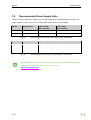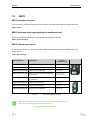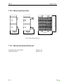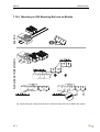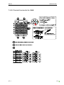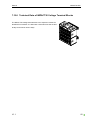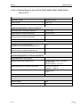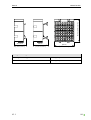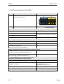
1
Manual IMPACT20 EtherNet/IP System Description Configuration Mounting and Installation Diagnostics and LED Dislays EtherNet/IP Bus System Technical Data Manual IMPACT20 EIP Publisher's Note Ethernet/IP IMPACT20 E DI16 Article Number: 56 916 IMPACT20 E DI8 DO8 Article Number: 56 917 IMPACT20 E DO16 Article Number: 56 918 Version 1.1 Edition 03_11 EN Article Number 56 935 Murrelektronik GmbH Falkenstrasse 3 D-71570 Oppenweiler Phone +49 (0) 71 91 47-0 Fax +49 (0) 71 91 47-130 [email protected] V1.1 2 Manual IMPACT20 EIP Service and Support Website: www.murrelektronik.com In addition, our Customer Service Center (CSC) will be glad to assist you: Our Customer Service Center can support you throughout your project during planning and the conception of customer applications, configuration, installation, and startup. We also offer competent consulting or – in more complex cases – we even provide direct onsite support. The Customer Service Center provides support tools. It performs measurements for fieldbus systems, such as PROFINET DP, DeviceNet, CANopen, and AS interface, as well as energy, heat, and EMC measurements. Our coworkers at the Customer Service Center provide their competence, know-how, and years of experience. They are familiar with how products made of various hardware and software manufacturers interact. You can contact the Customer Service Center at telephone number +49 (0) 71 91 47-424 or by email at [email protected]. V1.1 3 Manual IMPACT20 EIP About the User Manual and its Structure V1.1 4 Manual IMPACT20 EIP The following links will provide you with more information on bus systems, as well as the standards and specifications on which they are based: >>> ODVA (www.odva.org) V1.1 5 Manual IMPACT20 EIP Table of Contents Publisher's Note ....................................................................................................................................... 2 Service and Support ................................................................................................................................ 3 About the User Manual and its Structure ................................................................................................. 4 Table of Contents..................................................................................................................................... 6 Important Information ............................................................................................................................... 9 1 2 System Description ......................................................................................................................... 12 1.1 Description of the Impact20 Product Family ........................................................................... 12 1.2 System Components ............................................................................................................... 13 1.2.1 Product Designation Code ............................................................................................... 13 1.2.2 Product Overview ............................................................................................................. 13 1.2.3 System Design Principle .................................................................................................. 14 Configuration .................................................................................................................................. 15 2.1 Power Supply .......................................................................................................................... 15 2.1.1 3 2.2 Galvanic Isolation .................................................................................................................... 16 2.3 Electromagnetic Compatibility (EMC)...................................................................................... 16 Mounting and Installation ................................................................................................................ 20 3.1 Mounting .................................................................................................................................. 20 3.1.1 Mounting IMPACT20 Modules on DIN Mounting Rails .................................................... 20 3.1.2 Distances.......................................................................................................................... 21 3.1.3 Installation Position .......................................................................................................... 21 3.1.4 Addressing ....................................................................................................................... 22 3.2 Wiring Terminals...................................................................................................................... 23 3.2.1 Connecting Sensors and Actuators ................................................................................. 23 3.2.2 Terminal Overviews of IMPACT20 Modules .................................................................... 24 3.3 4 Configuration Notes ......................................................................................................... 15 Installing the ETHERNET/IP ................................................................................................... 28 ETHERNET/IP Bus System ............................................................................................................ 29 4.1 V1.1 Startup ..................................................................................................................................... 29 6 Manual 5 4.1.1 Assigning and Setting the IP Address .............................................................................. 30 4.1.2 EDS Files ......................................................................................................................... 35 4.1.3 IMPACT20 Web Server.................................................................................................... 35 4.1.4 Configuring the IMPACT20 in RSLogix5000.................................................................... 36 4.1.5 I/O Data ............................................................................................................................ 39 Diagnostics and LED DIsplays ....................................................................................................... 43 5.1 Function of Bus Status LEDs .................................................................................................. 43 5.2 Module and Actuator Power Supplies ..................................................................................... 45 5.2.1 Threshold Values of the Module Power Supply UI .......................................................... 45 5.2.2 Threshold Values of the Power Supply UA ...................................................................... 45 5.2.3 LED Displays UI and UA .................................................................................................. 46 5.3 6 IMPACT20 EIP Signal-Logic Display and LED Response ............................................................................... 47 5.3.1 Correlation Between Signal-logic Display and LED Response at the Input .................... 47 5.3.2 Correlation Between Signal-logic Display and LED Response at the Output .................. 47 5.4 Short-Circuit or Overload of Sensor Power Supply US ........................................................... 48 5.5 Short-Circuit or Overload of Actuators .................................................................................... 48 Technical Data ................................................................................................................................ 49 6.1 ETHERNET/IP IP20 Modules.................................................................................................. 49 6.1.1 7 Dimensioning ................................................................................................................... 52 Accessories .................................................................................................................................... 53 7.1 Label Sheets............................................................................................................................ 53 7.2 Coding Elements for Terminals ............................................................................................... 53 7.3 Blind Plugs RJ45 ..................................................................................................................... 53 7.4 Fieldbus Cables ....................................................................................................................... 53 7.5 Fieldbus Connectors ............................................................................................................... 54 7.6 Fieldbus System Components ................................................................................................ 54 7.7 I/O Cable ................................................................................................................................. 54 7.8 Recommended Power Supply Units ....................................................................................... 55 7.9 MICO ....................................................................................................................................... 56 7.10 V1.1 Voltage Terminal Block ........................................................................................................ 57 7 Manual IMPACT20 EIP 7.10.1 Description ....................................................................................................................... 57 7.10.2 Mounting Dimensions....................................................................................................... 58 7.10.3 Mounting Position/Distances ............................................................................................ 58 7.10.4 Mounting on DIN Mounting Rail and on Module .............................................................. 59 7.10.5 Installation ........................................................................................................................ 60 7.10.6 Technical Data of IMPACT20 Voltage Terminal Blocks .................................................. 62 Glossary ................................................................................................................................................. 67 Legal Provisions ..................................................................................................................................... 69 V1.1 8 Manual IMPACT20 EIP Important Information Basic Knowledge Required This manual contains general information on the system and the product. To understand this manual, you need to know about automation systems. Symbols and Icons This manual contains information and instructions you must comply with in order to maintain safety and avoid personal injury or damage to property. They are identified as follows: Notes indicate important information. Warnings contain information that, if ignored, may cause damage to equipment or other assets or, if you fail to comply with safety precautions, may constitute a danger to the user's health and life. These instructions are recommendations issued by Murrelektronik. V1.1 9 Manual IMPACT20 EIP Intended Purpose Before starting the devices, read this manual carefully. Keep it in a location that is accessible to all users at all times. The products that are described in this manual were developed, manufactured, tested, and documented in compliance with the relevant safety standards. In normal cases, these products do not constitute any danger to persons or objects, provided the handling specifications and safety instructions described in this manual are observed. They meet the specifications of the European EMC Directive (2004/108/EC). WARNING Devices from the IMPACT20 series are not safety devices conforming to the relevant standards. Do not use the OFF state of the outputs to implement safety-related requirements of the system/machine. The products are designed for industrial use. An industrial environment is defined as one in which loads are not connected directly to the public low-voltage power grid. Additional measures must be taken if the products are used in private, business, or trade environments. The safe, troublefree functioning of the products requires proper transportation, storage, mounting, and careful operation. Operation of the devices for their intended purposes is only guaranteed when the devices are fully mounted. Current safety and accident prevention laws valid for a specific application must be observed for the configuration, installation, setup, maintenance, and testing of the devices. The power supply must comply with SELV or PELV. Power sources in accordance with EN 61558-2-6 (transformer) or EN 60950-1 (switched-mode power supply) meet these requirements. Only use cables that meet the requirements and regulations for safety, electromagnetic compatibility, and, if necessary, telecommunications terminal equipment specifications. Information on cables and accessories made by Murrelektronik GmbH for this product is contained in Chapter Accessories. V1.1 10 Manual IMPACT20 EIP Qualified Personnel Only qualified, trained electricians knowledgeable in the safety standards of automation systems may configure, install, set up, maintain, and test the devices. The requirements concerning qualified personnel are dependent on the requirements profiles described in ZVEI and VDMA. For this reason, electricians must know the contents of the manual "Weiterbildung in der Automatisierung" (Further Training in Automation Systems) issued by ZVEI and VDMA and published by Maschinenbau-Verlag, Post Box 710864, 60498 Frankfurt, Germany) before installing and maintaining the devices. They are therefore electricians who are capable of assessing the work executed and any possible dangers arising from this due to their professional training, knowledge, experience, and their knowledge of the pertinent standards; or who have a level of knowledge equivalent to professional training due to their many years of activity in a comparable field. Only Murrelektronik technical personnel are allowed to execute work on the hardware and software of our devices, if they are devices not described in this manual. Unqualified tampering with the hardware or software, or failure to observe the warnings cited in this manual may result in severe personal injury or damage to property. V1.1 11 Manual IMPACT20 EIP 1 System Description 1.1 Description of the Impact20 Product Family IMPACT20 is a compact fieldbus I/O station. It combines 8 inputs and 8 outputs or 16 inputs or 16 outputs in a confined space. Due to its compact dimensions, the IMPACT20 is designed for use in switch cabinets, terminal boxes, and on control panels. An IMPACT20 module comprises a fieldbusspecific connection and a fixed number of I/O slots. The I/O functions are module-dependent and are unchangeable. All I/O connections are designed as spring-loaded clamping terminals. They are clearly arranged so that functional relationships are logically recognizable. The IMPACT20 product family groups signals at I/O level decentrally and places this information on the fieldbus (e.g. Ethernet/IP). Fieldbus Protocols Impact20 is supplied for the following fieldbus protocols: • PROFIBUS • CANopen • DeviceNet • EtherCAT • Ethernet/IP • Ethernet/IP Module variants • Module with 16 digital inputs • Module with 8 digital inputs and 8 digital outputs • Module with 16 digital outputs Functions • Easy to recognize, directly assigned status and diagnostic LEDs • Clear, unmistakable slot designation • Signal identification on the module • Terminal-specific disconnection in the event of an error • Group diagnostic and single-channel short-circuit diagnostic over the bus V1.1 12 Manual IMPACT20 EIP 1.2 System Components 1.2.1 Product Designation Code The designation of the IMPACT20 product family is based on a scheme that indicates the fieldbus and I/O function of individual devices. Examples: Name IMPACT20 Description E DI8 DO8 I/O channels D = Digital I O = Input = Output Fieldbus System P = ProfiBus C = CANopen DN = DeviceNet EC = EtherCat E = EtherNet/IP PN = PROFINET IO Product Family Fig. 1: Example of product designation 1.2.2 Product Overview Article Number Description 56 916 IMPACT20 E DI16 56 917 IMPACT20 E DI8 DO8 56 918 IMPACT20 E DO16 Tab. 1: ETHERNET/IP fieldbus modules V1.1 13 Manual 1.2.3 IMPACT20 EIP System Design Principle Device E EtherNet/IP Device Device Fig. 2: System design principle V1.1 14 Manual 2 IMPACT20 EIP Configuration This chapter contains information that is relevant during the electromechanical planning phase. 2.1 Power Supply 2.1.1 Configuration Notes Bus modules require a DC voltage power supply of typically 24 VDC (SELV / PELV) that must comply with the regulations for conventional industrial power supplies. To optimize immunity from interference, we advise you to tap sensor, bus and actuator power supply from a number of different power sources. Primary switched-mode or regulated power supplies should be used. Power supply unit performance is dependent on the number and power requirements of the connected users. In any case, make sure that the system voltage – measured at the most remote slave – does not drop below 18 VDC when viewed from the system power supplies. System response becomes undefined if the sensor and bus power supply drops below 18 VDC. IMPACT20 modules then generate an undervoltage diagnostic visually and over the fieldbus. Primary switched-mode power supply units generally permit an increase in output voltage via nominal voltage in order to compensate for line losses. Modules with digital inputs support the direct connection of commercially available sensors. Depending on the total power requirements resulting from the number of slaves, or the use of sensors with high power consumption, a separate power supply may be required for the sensors. V1.1 15 Manual 2.2 IMPACT20 EIP Galvanic Isolation To optimize electromagnetic compatibility and increase bus stability, the bus must be galvanically isolated from the remaining electronics. Fig. 3: Impact20 modules – galvanic isolation 2.3 Electromagnetic Compatibility (EMC) The units comply with the requirements of EC Directive 2004/108/EC "Electromagnetic Compatibility". These units conform with Class A devices. They may cause radio interference in residential areas. In this case, the operator may be required to implement suitable countermeasures. The devices described in this manual meet the relevant standards for electromagnetic compatibility in themselves. However, this does not assume that their electromagnetic compatibility is also guaranteed when built into a system. For this reason, the user is urgently advised to observe the instructions below concerning installation in accordance with EMC requirements. Protection Against Electrostatic Discharge The products described in this manual contain complete semiconductor components that may be destroyed or damaged by electrostatic discharge (ESD). V1.1 16 Manual IMPACT20 EIP Damage does not necessarily lead to an immediately detectable failure or malfunction. However, it may become evident with a delayed reaction or sporadically. When handling these devices, make sure that the safety precautions for ESD-sensitive devices that are well-known in general practice are maintained. In particular, note the following items: Do not disconnect or connect plugs or connectors live. The person handling the devices must discharge themselves electrostatically before they come in direct contact with the devices, e.g. by touching a grounded part of the system, or by wearing an ESD antistatic wrist strap connected to ground. Grounding A short (as short as possible) low-impedance connection is required between the grounding point and reference ground to discharge interference voltages that act between the device and reference ground. The inductance of normal FE cables represents a high impedance for high-frequency interference voltages. Make sure that the DIN mounting rail, on which the device is mounted, has a lowimpedance connection to ground. Wiring Arrangement Avoid EMC problems by keeping to the following basic rules of wiring arrangement: • Route the data wiring at the greatest possible distance from the power lines. Keep a minimum distance of 10 cm. • Only cross data and power lines at right angles. • Route data wires and power cables in separate, shielded ducts. • Take into consideration the potential interference of other devices or wires when arranging wires. • Keep the greatest possible distance from frequency converters, motor cables, and other devices, and from cables that emit high-frequency interference. V1.1 17 Manual IMPACT20 EIP Power Failures and Dips Transient power failures and dips (<10 ms) do not normally impair operation since the power supply to the electronics is buffered by integrated capacitors. However, this does not apply to the power supply of sensors and actuators connected to the module. Their high power demand can not be met by capacitors integrated in the device. For this reason, short-term interruptions in actuator voltage may cause undesired switching operations. If an input signal that lasts for less than 1 ms changes, the input filters prevent the change of the input state reported to the controller. Longer interruptions to sensor power supply may lead to an input signal change. Separate Power Supplies Sensors and actuators can be powered by a separate power supply unit. A separate power supply improves the electromagnetic compatibility of the overall system. Suppression of Inductive Loads The outputs of the devices described in this manual have an integrated protection circuit against highenergy interference voltages, e.g. that occur when inductive loads are switched. Inductive load (e.g. solenoid valve) Varistor or bipolar suppressor diode Fig. 4: Suppression of Inductive Loads A suppressor diode guarantees rapid reduction in the energy stored in the magnetic field of an inductive load. However, with inductive loads, e.g. loads within the maximum current carrying capacity range of a channel and at switching frequencies > 1 Hz, we advise the use of commercially available protection circuits that are capable of reducing the energy stored in the connected inductances. The high voltages when inductive loads are switched off generate strong fields in the wiring and this may lead to interference in adjacent circuits or devices. Murrelektronik offers a wide selection of suppressor products. Refer to our catalog or visit our online shop at www.murrelektronik.com V1.1 18 Manual IMPACT20 EIP Other Measures and Limits In specific system configurations, the requirements for interference emission and immunity from interference can only be met with additional measures since the EMC within a system is dependent on the individual components made by other manufacturers. Mains filters are a suitable measure to reduce cable-bound interference. Various manufacturers offers optical-fiber converters. This type of data transmission is basically immune to EMC interference. However, it does not apply to the converter electronics. Therefore, use of fiber-optics does not eliminate all EMC problems. Our accredited test center will answer any further queries you may have concerning EMC. There you will receive advice on certain methods to conform with the EMC Directive for the systems you have built. Murrelektronik-Prüfzentrum (Test Center), Grabenstrasse 27, D-71570 Oppenweiler, Phone +49 (0) 71 91 47-334, Fax +49 (0) 71 91 47-323, [email protected] V1.1 19 Manual IMPACT20 EIP 3 Mounting and Installation 3.1 Mounting 3.1.1 Mounting IMPACT20 Modules on DIN Mounting Rails Make sure that the DIN mounting rail, on which the device is mounted, has a lowimpedance connection to ground. Fig. 5: Mounting IMPACT20 modules on DIN mounting rails V1.1 20 Manual 3.1.2 IMPACT20 EIP Distances Fig. 6: Distances 3.1.3 Installation Position Fig. 7: Installation position V1.1 21 Manual IMPACT20 EIP 3.1.4 Addressing 78 - DHCP / BOOTP 9 01 1 ... 254 - IP Address Byte 4 998 - Factory settings 999 - Static IP 78 78 456 23 9 01 0 23 23 9 01 x 10 4 56 X 100 x1 4 56 IP Address Byte 1 Byte 2 Byte 3 Byte 4 Fig. 8: Setting addresses on IMPACT20 modules Further information on addressing is contained in the chapter on Startup. V1.1 22 Manual IMPACT20 EIP 3.2 Wiring Terminals 3.2.1 Connecting Sensors and Actuators WARNING Devices from the IMPACT20 series are not safety devices conforming to the relevant standards. Do not use the OFF state of the outputs to implement safety-related requirements of the system/machine. 3.2.1.1 Sensor Power Supply Sensor can be powered by the IMPACT20 module. The sensor power supply is protected by a selfresetting short-circuit proof transistor for each module. The maximum current draw for the sensor power supply is 0.7 A per module. 3.2.1.2 Actuators The maximum current draw of IMPACT20 modules per channel is 2 A. Please remember that the maximum total current of 8 A at the UA terminal may not be exceeded. CAUTION If the polarity of the module and actuator power supplies are reversed, this may damage the module. V1.1 23 Manual 3.2.2 IMPACT20 EIP Terminal Overviews of IMPACT20 Modules 3.2.2.1 DI16 Modules A Adressierung B Ethernet/IP Port C Klemmen / terminals terminales / bornes B DI B ... C (X0...X3) UI 0V (X0) (X0) FE (X3) UI n.c. 0V (X1) (X1) US 0V (X2) (X2) 00...03 (CH 00...CH 03) (X0) S 00...03 (CH 10...CH 13) (X1) 0V 00...03 (CH 20...CH 23) (X2) 00...03 (CH 30...CH 33) (X3) Fig. 9: Terminal overview of Impact20 DI16 modules V1.1 24 Manual IMPACT20 EIP 3.2.2.2 DI8 DO8 Modules A Adressierung B Ethernet/IP Port C Klemmen / terminals terminales / bornes B DO DI B C (X0...X3) UI 0V (X0) (X0) FE (X3) UI UA UA (X1) 0V (X1) ... 00...03 (CH 20...CH 23) (X2) ... 00...03 (CH 00...CH 03) US 0V (X2) (X2) (X0) 00...03 (CH 30...CH 33) (X3) 00...03 (CH 10...CH 13) S (X1) 0V Fig. 10: Terminal overview of Impact20 DI8DO8 modules V1.1 25 Manual IMPACT20 EIP 3.2.2.3 DO16 Modules A Adressierung B Ethernet/IP Port C Klemmen / terminals terminales / bornes B DO B C (X0...X3) FE (X3) UI 0V (X0) (X0) UI UA UA (X1) 0V (X1) ... 00...03 (CH 00...CH 03) (X0) n.c. (X2) 0V (X2) 00...03 (CH 10...CH 13) (X1) 00...03 (CH 20...CH 23) (X2) 00...03 (CH 30...CH 33) (X3) Fig. 11: Terminal overview of Impact20 DO16 modules Murrelektronik offers label sheet Art. No. 56113 to label the terminals. Please refer to our Catalog. V1.1 26 Manual IMPACT20 EIP Fig. 12: Wiring terminals 3.2.2.4 Removing terminals Fig. 13: Removing terminals V1.1 27 Manual 3.3 IMPACT20 EIP Installing the ETHERNET/IP Impact20 modules can be integrated in the ETHERNET/IP network in star or bus topologies. IOController Fig. 14: ETHERNET/IP system in star topology Two RJ45 sockets for ETHERNET/IP are located on the Impact20 module. One socket is for incoming signals, the other is for looping through the ETHERNET/IP. A maximum of 9 modules can be connected in series. Fig. 15: ETHERNET/IP in bus topology V1.1 28 Manual IMPACT20 EIP 4 ETHERNET/IP Bus System 4.1 Startup First use the rotary switch, a DHCP/BOOTP server, or the web server to assign an IP address to all connected IMPACT20 modules. Please refer to the next chapter "Issuing and Setting the IP Address" for precise instructions. In any case, make sure that you issue each address only once. Then connect your IMPACT20 modules by means of an RJ45 Ethernet cable to an EthernetIP controller and connect your sensors and/or actuators using RJ45 cables. Only then hook up the power supply using a spring-loaded terminal. Configure your controller as described in Chapter "Configuring the IMPACT20 in RSLogix50004.2.3", for example to a RSLogix5000 controller. Before starting the setup, make sure you check that the fieldbus is connected properly in accordance with the system structure. Each device type possesses an EDS file (*.eds) and a graphic (*.bmp). See more details in Chapter "4.2.1 EDS Files". V1.1 29 Manual IMPACT20 EIP 4.1.1 Assigning and Setting the IP Address Issuing Addresses using the BCD Rotary Switch 78 456 23 9 01 78 0 - DHCP / BOOTP 9 01 1 ... 254 - IP Address Byte 4 998 - Factory settings 999 - Static IP 23 23 9 01 x 10 78 X 100 456 4.1.1.1 x1 456 IP Address Byte 1 Byte 2 Byte 3 Byte 4 Fig. 16: Issuing addresses using the BCD rotary switch Set the operating mode using the three rotary switches to obtain the IP address of the module: When issuing addresses, please note the following: Every Ethernet user must be assigned an unambiguous and unique IP address in the network. Position/Range Settings Position 0: IP address request per DHCP (default), or BOOTP without saving ( ) Range 1 to 254: Setting the last byte of the IP address (default 192.168.100.xxx) Range 255 to 997: IP address request per DHCP (default), or BOOTP with saving ( ) The search for an IP address only takes place if the setting DHCP or BOOTP was selected in the web server (Slot 000 / Properties). If STATIC was selected, the stored IP address is used. Position 998: Accept factory settings Position 999: Use static IP (default 192.168.100.6) Tab. 2: Setting the IP address using the rotary switches It is only possible to set the DHCP and BOOTP modes to refer to the IP address in the web server. V1.1 30 Manual IMPACT20 EIP Note down the MAC ID printed on the underside of the housing and set the rotary switches to the required positions. Boot your DHCP or BOOTP server and assign the required IP address to the module MAC ID that you noted down earlier. After the system is booted, start the service you require depending on the service you selected, and fetch the IP address from the server. If you saved the IP addresses, set all rotary switches to "999", otherwise this service is re-executed after every reboot. The rotary switch settings are loaded once after applying the power supply. Any change only becomes effective after a power reset. If you want to use a saved IP address, set the rotary switch to 999. When you issue an IP address or a subnet mask, make sure it corresponds to your actual network configuration. If you make a false input, you may no longer be able to reach your module under certain circumstances. Therefore, first contact your system administrator! If the IP address is obtained from a DHCP/BOOTP server, the module requests an IP address only within 60 seconds after switchon. Make sure that a DHCP/BOOTP server is running when the module is switched on. Switch position "255 to 997" Use this switch position when you want to store the IP address in the bus node and obtain the address from a BOOTP or DHCP server. It is then possible to switch over the bus node to static IP address. The stored IP address is used. Use the web server to perform the switchover. If you set the bus mode to a static IP address, the device expects an address to be issued by a DHCP/BOOTP server every time the device is switched. Switch position "998" The bus node factory settings are reactivated in switch position "998". The IP configuration, the I/O module settings, the diagnostic methods, and the number of diagnostic buffers are reset. V1.1 31 Manual 4.1.1.2 IMPACT20 EIP Issuing Addresses using DHCP / BOOTP If you want to issue an IP address using DHCP or BOOTP, the IMPACT20 module sends only four DHCP requests or four BOOTP requests. Note down the MAC ID printed on the right side of the housing and set the rotary switch to the required position. Boot your DHCP or BOOTP server and assign the required IP address to the MAC ID of the module that you noted down earlier. After system boot, the IP addresses are obtained from the server. If you saved the IP addresses, now set all rotary switches to "999", otherwise this service is reexecuted after every reboot. The rotary switch setting is loaded once after applying the power supply. Any change only becomes effective after a power reset. If you want to use a saved IP address, set the rotary switch to 999. CAUTION: When you issue an IP address or a subnet mask, make sure it corresponds to your actual network configuration. If you make a false input, you may no longer be able to reach your IMPACT20 system under certain circumstances. Therefore, first contact your system administrator! V1.1 32 Manual 4.1.1.3 IMPACT20 EIP Issuing Addresses using the Web Server The method or the IP address can be set in the web server under the "Edit IMPACT20" link under the "Properties" tab.. Fig. 17: Setting the IP in the web server Display Description „Method of IP Resolution“ To select the method, use the selection menu next to "Method of IP Resolution". Click on the method you require. If you select "Static", the saved IP address is used at the next reboot irrespective of the switch setting, and no DHCP or BOOTP request is sent. Below that, the screen displays the currently used and saved IP address. Please note that the two addresses may be different. V1.1 33 Manual IMPACT20 EIP Display Description „New IP Adress“ „New Subnet Mask“ You can enter a new IP address or subnet mask next to the "New IP Address" and "New Subnet Mask" selection boxes. „Save Settings & Reset System“ When you have completed all the settings, please press the "Save Settings & Reset System" button to save all your settings. Execute an IMPACT20 system reset to activate the changed settings. „Selection of I/O Length Mode” In the “Selection of I/O Length Mode” field, set whether you want the device to work with even I/O data lengths or whether the data length should remain unchanged. True I/O Length: The data length leaves un changed. Always Even I/O Length: With odd data length a byte is added. „MAC-Address“ Shows the MAC Address of the device. The function of the "Static" setting in the "Method of IP Resolution" list box means there is no IP address inquiry over DHCP or BOOTP, even when the switch position is set to 255 to 998 or 0. Instead, the address that is already saved is used. 4.2 Factory Settings The factory settings are: Description Value Method of IP Resolution DHCP Currently Used IP 192.168.100.6 Stored IP 192.168.100.6 Subnet Mask 255.255.255.0 Selection of I/O Length Mode True I/O Length Tab. 3: Factory settings There is no stored configuration in the device. The factory settings can be restored by setting the rotary switch to "998". V1.1 34 Manual IMPACT20 EIP 4.2.1 EDS Files The EDS file is created explicitly for the module type (I/O). The consequence is that, in the IMPACT20 series, each module is assigned a unique EDS file with the affix "*.eds". The modules are also assigned a uniform icon with the suffix "*.ico". The EDS file contains a lot of information concerning the module e.g.: device type, manufacturer, vendor ID, article number, software version, hardware version, etc. EDS files are module-specific. Only Murrelektronik technical personnel are allowed to perform application-specific modifications. EDS files are assigned as shown in the table below: Module type Name of EDS file Name of icon IMPACT20 E DI16 IMPACT20-E DI16 56916.eds IMPACT20.ico IMPACT20 E DI8 DO8 IMPACT20-E DI8 DO8 56917.eds IMPACT20.ico IMPACT20 E DO16 IMPACT20-E DO16 56918.eds IMPACT20.ico Tab. 4: EDS files The latest EDS files are downloadable over the web from: http://www.murrelektronik.com. Navigate to the download section under configuration files. 4.2.2 IMPACT20 Web Server All IMPACT20 EthernetIP modules have a web server that is accessible via the IP address of each module. To ensure the correct graphic display, please install the latest version of a web browser on your PC (Mozilla Firefox Version 3.5 or higher, or Microsoft Internet Explorer, Version 7.0 or higher). The start page provides you with information on the connected module: • Size of assembly instances • Article number V1.1 35 Manual • IMPACT20 EIP Software version You can retrieve the software versions of the firmware, its date of creation, and the version of your web under the option "Help -> Version Info". When you issue an IP address using the web server, please refer to Section 4.1.1. 4.2.3 Configuring the IMPACT20 in RSLogix5000 The procedure may differ slightly depending on the controller used. In this example, a CompactLogix from Allen Bradley is used. Go to the backplane and your EtherNET port in RSLogix5000 under option "I/O Configuration". Click right on "Ethernet" and select "New Module". The screen below appears: Fig. 18: RSLogix5000 generic Ethernet modules Expand the "Communications" menu option and select the module "Ethernet Module – Generic Ethernet Module". When you configure the module RSLogix, make absolutely sure that you select "Ethernet Module - Generic Ethernet Module". V1.1 36 Manual IMPACT20 EIP Then enter the required parameters. Fig. 19: RSLogix – Entering data lengths The bus node uses the following instances: • Inputs: Assembly Instance 100dec • Outputs: Assembly Instance 112dec • Configuration Assembly Instance 128dec Please note that the instance 128dec is not supported for the configuration and therefore the size must always be ZERO! Please note that IMPACT20 calculates data lengths in bytes. For this reason, make sure you set the correct data type, in our example SINT (8 bits). V1.1 37 Manual IMPACT20 EIP Set the RPI time in the "Connection" tab. The default RPI is 10 ms. Fig. 20: RSLogix5000 Setting the RPI time When you have completed all the settings, click on the "OK" button. Go to the Offline button and download the configuration to the controller. Based on the previous data settings, the controller verifies the correct data lengths and instances, and if correct, establishes the connection with the bus node. The bus node then switches the NS-LED to static green. Configurations that require RPI times under 10 ms must first be tested for correct operation. The minimum RPI time supported by IMPACT20 is 5 ms! V1.1 38 Manual IMPACT20 EIP 4.2.4 I/O Data 4.2.4.1 True I/O Length Mode The table displays the input and output instances for each module with the corresponding length: Module Assembly Instance Input Assembly Instance Output Assembly Instance Configuration IMPACT20 E DI16 Art. No. 56916 100dec Length: 3 (8 bits) 112dec Length: 1 (8 bits) 128dec Length: 0 IMPACT20 E DI8 DO8 Art. No. 56917 100dec Length: 3 (8 bits) 112dec Length: 1 (8 bits) 128dec Length: 0 IMPACT20 E D016 Art. No. 56918 100dec Length: 3 (8 bits) 112dec Length: 2 (8 bits) 128dec Length: 0 4.2.4.2 Always Even I/O Length Mode The table displays the input and output instances for each module with the corresponding length: Module Assembly Instance Input Assembly Instance Output Assembly Instance Configuration IMPACT20 E DI16 Art. No. 56916 100dec Length: 4 (8 bits) 112dec Length: 2 (8 bits) 128dec Length: 0 IMPACT20 E DI8 DO8 Art. No. 56917 100dec Length: 4 (8 bits) 112dec Length: 2 (8 bits) 128dec Length: 0 IMPACT20 E D016 Art. No. 56918 100dec Length: 4 (8 bits) 112dec Length: 2 (8 bits) 128dec Length: 0 V1.1 39 Manual IMPACT20 EIP 4.2.4.3 I/O Data IMPACT20 E DI16 Art. No. 56916 Manufacturer-specific format with 16-bit inputs and group diagnostics for the module. Assembly instances 100dec and 112dec are used. Assembly instance 100dec: Byte Bit 7 Bit 6 Bit 5 Bit 4 Bit 3 Bit 2 Bit 1 Bit 0 0 Input channel 13 Input channel 12 Input channel 11 Input channel 10 Input channel 03 Input channel 02 Input channel 01 Input channel 00 1 Input channel 33 Input channel 32 Input channel 31 Input channel 30 Input channel 23 Input channel 22 Input channel 21 Input channel 20 2 Reserved Reserved Reserved Reserved Reserved Sensor shortcircuit diagnostic Reserved Sensor power supply undervoltage diagnostic 3 0x00 Dashed line: The „Always Even I/O Length Mode“ adds a further bit. Assembly instance 112dec: Reserved V1.1 40 Manual IMPACT20 EIP 4.2.4.4 I/O Data IMPACT20 E DI8 DO8 Art. No. 56917 Manufacturer-specific format with 8-bit outputs, group diagnostic for the module, actuator short-circuit diagnostic channel-wise, and with 8-bit outputs. Assembly Instances 100dez and 112dez are used. Assembly instance 100dec: Byte Bit 7 Bit 6 Bit 5 Bit 4 Bit 3 Bit 2 Bit 1 Bit 0 0 Input channel 13 Input channel 12 Input channel 11 Input channel 10 Input channel 03 Input channel 02 Input channel 01 Input channel 00 1 Reserved Reserved Reserved Reserved Group signal Actuator shortcircuit diagnostic Sensor shortcircuit diagnostic Actuator power supply undervoltage diagnostic Sensor power supply undervoltage diagnostic 2 Actuator shortcircuit channel 33 Actuator shortcircuit channel 32 Actuator shortcircuit channel 31 Actuator shortcircuit channel 30 Actuator shortcircuit channel 23 Actuator shortcircuit channel 22 Actuator shortcircuit channel 21 Actuator shortcircuit channel 20 3 0x00 Assembly instance 112dec: Byte Bit 7 Bit 6 Bit 5 Bit 4 Bit 3 Bit 2 Bit 1 Bit 0 0 Output channel 33 Output channel 32 Output channel 31 Output channel 30 Output channel 23 Output channel 22 Output channel 21 Output channel 20 1 0x00 Dashed line: The „Always Even I/O Length Mode“ adds a further bit. V1.1 41 Manual IMPACT20 EIP 4.2.4.5 I/O Data IMPACT20 E DO16 Art. No. 56918 Manufacturer-specific format with 16-bit outputs, group diagnostic for the module, actuator short-circuit diagnostic channel-wise, and with 16-bit outputs. Assembly instances 100dec and 112dec are used. Assembly instance 100dec: Byte Bit 7 Bit 6 Bit 5 Bit 4 Bit 3 Bit 2 Bit 1 Bit 0 0 Reserved Reserved Reserved Reserved Group signal Actuator shortcircuit diagnostic Reserved Actuator power supply undervoltage diagnostic Sensor power supply undervoltage diagnostic 1 Actuator shortcircuit channel 13 Actuator shortcircuit channel 12 Actuator shortcircuit channel 11 Actuator shortcircuit channel 10 Actuator shortcircuit channel 03 Actuator shortcircuit channel 02 Actuator shortcircuit channel 01 Actuator shortcircuit channel 00 2 Actuator shortcircuit channel 33 Actuator shortcircuit channel 32 Actuator shortcircuit channel 31 Actuator shortcircuit channel 30 Actuator shortcircuit channel 23 Actuator shortcircuit channel 22 Actuator shortcircuit channel 21 Actuator shortcircuit channel 20 3 0x00 Assembly instance 112dec: Byte Bit 7 Bit 6 Bit 5 Bit 4 Bit 3 Bit 2 Bit 1 Bit 0 0 Output channel 13 Output channel 12 Output channel 11 Output channel 10 Output channel 03 Output channel 02 Output channel 01 Output channel 00 1 Output channel 33 Output channel 32 Output channel 31 Output channel 30 Output channel 23 Output channel 22 Output channel 21 Output channel 20 Dashed line: The „Always Even I/O Length Mode“ adds a further bit. V1.1 42 Manual 5 IMPACT20 EIP Diagnostics and LED DIsplays All IMPACT20 modules have separate and well arranged LEDs for device and I/O status. These displays are located on the front of the device. The following diagnostics are displayed visually and signaled over the fieldbus: • Sensor short-circuit as group signal • Actuator short-circuit channel-wise and group signal • Module power supply undervoltage UI (module power supply is less than 18 V). • Actuator power supply undervoltage UA (actuator power supply is less than 18 V). 5.1 Function of Bus Status LEDs Fig. 21: PROFINET module: Bus LEDs The device performs a self-test as soon as the IMPACT20 is powered over the bus. The self-test lasts for approx. 2 s. It is followed by the DupMac Test. This checks whether there are other modules with an identical MAC ID on the bus. On completion of the DupMac Test, the NS-LED flashes green. If the V1.1 43 Manual IMPACT20 EIP DupMac Test fails, the NS-LED lights up red and a free address must be set using the rotary switches on the module. A power reset must be performed. 5.1.1.1 Signal States of Bus Status LEDs Bus status LEDs on module front panel LED Designation LED Display Response Meaning MS off Device is off MS green Operational, device in service MS green / red flashing Self-test NS off Device is off Device has no IP address NS flashing green IP address exists but no connection to the Master NS green Connection to Master exists NS flashing red At least one connection has timeout NS red The module detected that its IP address is used by a different device NS green / red flashing Self-test Tab. 5: Bus status LEDs on module front panel V1.1 44 Manual 5.2 IMPACT20 EIP Module and Actuator Power Supplies An LED is provided for each of the module power supply terminals "UI" and actuator power supply terminals "UA". • The LEDs under "UI“ show the status of the module and sensor power supplies. • The LEDs under "UA“ show the status of the digital outputs. 5.2.1 Threshold Values of the Module Power Supply UI There are two thresholds for undervoltage detection: 12 V < UI < 18 V < 12 V The device continues to function but • The UI LED lights up red. • The associated diagnostic was transferred to the Master. The device performs a power reset. All outputs are reset to 0. 5.2.2 Threshold Values of the Power Supply UA There is one threshold for undervoltage detection: 12 V < UA < 18 V < 12 V V1.1 The device continues to function but • The UA LED lights up red. • The associated diagnostic was transferred to the Master. • The UA LED is off. • All outputs are reset to 0. 45 Manual 5.2.3 IMPACT20 EIP LED Displays UI and UA LED Displays UI and UA Response State Green Power supply OK (≥ 18 V) Red Undervoltage (< 18 V) Off Voltage ≤ approx. 12 V Tab. 6: LED module power supply Please note that the sensor power supply voltage (US terminal) is connected internally to the module power supply voltage (UI terminal). This ensures that the two terminals have the same voltage. V1.1 46 Manual 5.3 IMPACT20 EIP Signal-Logic Display and LED Response A separate status display is assigned to every channel. This is labeled "00 to 03". The status display is located below the associated terminal and shows the status of the inputs and outputs. 5.3.1 Correlation Between Signal-logic Display and LED Re- sponse at the Input LED Display Logic Value Voltage at Input Signal Off 0 < 11 V Input with NO contact function yellow 1 11 to 30.2 V (dependent on US) Tab. 7: LED at input of digital modules 5.3.2 Correlation Between Signal-logic Display and LED Re- sponse at the Output LED Display Logic Value Voltage at output Signal Off 0 0V Output yellow 1 12 to 30.2 V (dependent on UA) Tab. 8: LED at output of digital modules V1.1 47 Manual 5.4 IMPACT20 EIP Short-Circuit or Overload of Sensor Power Supply US Reaction of IMPACT20 modules to short-circuit or overload of sensor power supply: • The bus transmits the diagnostic data to the Master. • The diagnostic LED at the associated terminal lights up red. LED Display US Response State Off Power supply OK Red Overload or short-circuit of sensor power supply. Tab. 9: LED periphery power supply After rectification of the overload or short-circuit, the sensor power supply is immediately available again. 5.5 Short-Circuit or Overload of Actuators Response of IMPACT20 modules to short-circuit or overload of outputs: • The bus transmits diagnostic data to the Master. • The diagnostic LED on the associated terminal lights up red. LED Display Response State Off / yellow Output with no overload / short-circuit Red Output in overload / short-circuit case Tab. 10: LED at output of digital modules After rectifying the overload or short-circuit, the output is only available after UA switchoff or channel reset. V1.1 48 Manual IMPACT20 EIP 6 Technical Data 6.1 ETHERNET/IP IP20 Modules IMPACT20 P DI16 Art. No.: 56916 IMPACT20 P DI8 DO8 Art. No.: 56917 IMPACT20 P DO16 Art. No.: 56918 General Terminals X0 and X1 Terminals X2 and X3 16 inputs 8 inputs 8 outputs 16 outputs EMC EN 61131-2 EN 61000-4-2 ESD EN 61000-4-3 RF-Field & GSM Product standard Contact ± 4 kV, air ± 8 kV 10 V/m EN 61000-4-4 Burst ± 2 kV DC inputs, ± 1 kV signal lines Asym./sym. ± 500 V EN 61000-4-5 Surge Asym. ± 1 kV EN 61000-4-6 HF-asymmetric 10 V EN 61000-4-8 Magnetic field 50 Hz 30 A/m EN 55011 Emission QP 40 dBµV/m (30 … 230 MHz) QP 47 dBµV/m (230 … 1000 MHz) Class B Ambient Conditions Operating temperature Storage temperature Enclosure type according to EN 60529 0°C ... +55 °C -20°C ... +70 °C IP 20 Mechanical Ambient Conditions Oscillation according to EN 60068 Part 2-6 Shock according to EN 60068 Part 2-27 5 … 60 Hz: constant amplitude 0,35 mm; 60 … 150 Hz: constant acceleration 5 g Amplitude 15 g, 11 ms duration Miscellaneous Dimensions (LxWxH) 117 x 56 x 47 mm Mounting dimension (L xW) 117 x 56 mm Weight Approx. 170 g V1.1 49 Manual IMPACT20 EIP IMPACT20 P DI16 Art. No.: 56916 IMPACT20 P DI8 DO8 Art. No.: 56917 IMPACT20 P DO16 Art. No.: 56918 Bus Data Transfer protocol Transfer rate Ethernet/IP 10/100 MBit/s, IEEE 802.3, Auto-Negotiation half- or full Duplex by 10 and 100 Mbit/s available, automatically settings Electrical isolation 500 V between bus and internal logic Vendor ID 640Dec Data length input and diagnostics Assembly Instance Input: 100; Size: 3 (8 bits) Data length output Assembly Instance Output: 112; Size: 1 (8 bits) Data length configuration Assembly Instance Configuration: 128; Size: 0 Connection Possibilities Sensor and actuator supply Cage clamp max. 2.5 mm² Bus connection 2 x RJ45 Sensor 4 x 4 terminal block connectors 2 x 4 terminal block connectors - Outputs - 2 x 4 terminal block connectors 4 x 4 terminal block connectors Maximum length of output cable - Maximum length of input cable with 0.75 mm² max. 10 m, with 0.34 mm² max. 5 m < 30 m - Power Supply Operating voltage range logic UI 18 … 30.2 V DC Current consumption (only, UI) 120 mA Actuator supply UA power over cage clamp connection max. 8 A Reverse voltage protection module electronics Yes Reverse voltage protection actuator supply Reverse voltage protection sensor supply US Overvoltage protection V1.1 - Yes Yes - Yes (suppressor diode) 50 Manual IMPACT20 EIP IMPACT20 P DI16 Art. No.: 56916 IMPACT20 P DI8 DO8 Art. No.: 56917 IMPACT20 P DO16 Art. No.: 56918 16 8 - Inputs Number of inputs Delay time for signal change Input characteristics 2 ms - EN 61131-2, Type 3 - Outputs Number of outputs - 8 16 Switching frequency - approx. 50 Hz, 50% duty ratio Actuator current load - approx. 2 A per actuator Switching frequency inductive load - approx. 10 Hz Lamp load - max. 40 W Sensor power supply US Max. current 0.7 A - Short circuit protection for sensors with automatic restart Yes - Reverse polarity protection Yes - Tab. 11: V1.1 Technical Data 51 Manual 6.1.1 IMPACT20 EIP Dimensioning Fig. 22: Dimensioning The dimensions of all IMPACT20 modules are identical. V1.1 52 Manual IMPACT20 EIP 7 Accessories 7.1 Label Sheets Article Number Description 56113 Label Sheets Tab. 12: 7.2 Accessories, Label Sheets Coding Elements for Terminals Article Number Description 56115 Coding elements for terminals Tab. 13: 7.3 Accessories, Coding Elements for Terminals Blind Plugs RJ45 Article Number Description 58150 Blind plugs RJ45 Tab. 14: 7.4 Accessories, blind plugs Fieldbus Cables Article Number Description 7000-00000-8409999 Bus cable for EtherNet/IP, 100 m collar 7000-99711-7960060 Bus cable RJ45 – RJ45, straight 0.6 m 7000-99711-7960100 Bus cable RJ45 – RJ45, straight 1.0 m 7000-99711-7960150 Bus cable RJ45 – RJ45, straight 1.5 m 7000-99711-7960300 Bus cable RJ45 – RJ45, straight 3.0 m Tab. 15: V1.1 Fieldbus cables 53 Manual 7.5 IMPACT20 EIP Fieldbus Connectors Article Number Description 7000-99051-0000000 RJ45 Ethernet connector, straight shielded, 4-pin, IP20 self-connecting Tab. 16: 7.6 Fieldbus connectors Fieldbus System Components Article Number Description 58154 TREE 4TX Unmanaged 4 Port Switch 58158 TREE 8TX Unmanaged 8 Port Switch Tab. 17: 7.7 Fieldbus system components I/O Cable Murrelektronik offers a wide range of actuator and sensor products. This ranges from connectors, cables, and adapters through to special-purpose requirements. Refer to our catalog or visit our inline shop at www.murrelektronik.com. V1.1 54 Manual 7.8 IMPACT20 EIP Recommended Power Supply Units Primary switched-mode power supply units from Murrelektronik are specially designed to power automation systems. For this reason, we recommend this system type to power modules. Phases Output power Input voltage 95 to 132 VAC Input voltage 185 to 265 VAC 1 240 W / 10 A 85086 85085 1 480 W / 20 A 85088 85087 Tab. 18: Recommended power supply units, MCS power+ single-phase Phases Output power Input voltage 3 x 340 to 460 VAC 3 240 W / 10 A 85095 3 480 W / 20 A 85097 3 960 W / 40 A 85099 Tab. 19: Recommended power supply units, MCSPower+ three-phase Murrelektronik offers a comprehensive selection of primary switched-mode power supply units. Refer to our catalog or visit our inline shop at www.murrelektronik.com. V1.1 55 Manual 7.9 IMPACT20 EIP MICO MICO monitors currents You can select a maximum individual current value for each channel and MICO monitors this value. LED = green MICO indicates when approaching the maximum load There is a visual alarm when 90% of the selected current load is reached. LED = green (flashing) MICO detects over-stress In case of short circuits or if the load current exceeds the selected value, MICO switches off the affected channel. LED = red (flashing) Article Number Description 9000-41034-0100400 MICO 4.4 (4 channels) 1, 2, 3, 4 9000-41034-0100600 MICO 4.6 (4 channels) 1, 2, 4, 6 9000-41034-0401000 MICO 4.10 (4 channels) 4, 6, 8, 10 9000-41034-0101000 MICO 4.4.10 ACTUATOR-SENSOR (4 channels) 2 x 1, 2, 3, 4 2 x 4, 6, 8, 10 9000-41034-0401005 MICO 4.10 SPEED-START (4 channels) 4, 6, 8, 10 9000-41042-0100400 MICO 2.4 (2 channels) 1, 2, 3, 4 9000-41042-0100600 MICO 2.6 (2 channels) 1, 2, 4, 6 9000-41042-0401000 MICO 2.10 (2 channels) 4, 6, 8, 10 Tab. 20: Current adjustment [A] Overview of MICO variants Murrelektronik offers a wide selection of products and accessories. Refer to our catalog or visit our inline shop at onlineshop.murrelektronik.com V1.1 56 Manual 7.10 IMPACT20 EIP Voltage Terminal Block Article Number Description 56078 Voltage terminal block gray / gray / brown / blue 56079 Voltage terminal block gray / gray / yellow / blue 56080 Voltage terminal block yellow / blue / yellow / blue 56081 Voltage terminal block brown / blue / brown / blue 56109 Voltage terminal block brown / brown / blue / blue 56110 Voltage terminal block blue / blue / yellow / yellow 56111 Voltage terminal block blue / yellow / brown / blue Tab. 21: Voltage terminal block accessories 7.10.1 Description Voltage terminal blocks are small aids that assist in the simple bridging or chaining of a required level or voltage. Fig. 23: Application information V1.1 57 Manual IMPACT20 EIP 70±0,5 (2,76 ±0,02 in.) 7.10.2 Mounting Dimensions 32,5 ±0,5 42±0,5 56±0,5 (1,28 ±0,02 in.) (1,65 ±0,02 in.) (2,20 ±0,02 in.) Fig. 24: Mounting dimensions 7.10.3 Mounting Position/Distances Einbaulage / Mounting position beliebig / any Abstand / Distance beliebig / any V1.1 58 Manual IMPACT20 EIP PLUGGING ON TO IMPACT20 MO- SNAP-ON 7.10.4 Mounting on DIN Mounting Rail and on Module Fig. 25: Mounting the voltage terminal block on DIN mounting rails and on IMPACT20 module V1.1 59 Manual IMPACT20 EIP 7.10.5 Installation 7.10.5.1 Terminal Overview Art. Nos. 56078, 56079, 56080, 56081, 56084, 56109, 56110, 56111 V1.1 60 Manual IMPACT20 EIP 7.10.5.2 Terminal Overview Art. No. 56082 V1.1 61 Manual IMPACT20 EIP 7.10.6 Technical Data of IMPACT20 Voltage Terminal Blocks The IMPACT20 voltage terminal block is an expansion module for all IMPACT20 modules. It is fitted with 4 terminal rows that are electrically connected in various ways. V1.1 62 Manual IMPACT20 EIP 7.10.6.1 Technical Data Art. Nos. 56078, 56079, 56080, 56081, 56084, 56109, 56110, 56111 Technische Daten / Technical data Spannung / voltage AC/DC max. 30 V Strom / current max. 10 A Umgebungsbedingungen / Ambient conditions Arbeitstemperatur / Operating temperature 0°C to +55°C Lagertemperatur / Storage temperature -40°C to +85°C Schutzart nach EN 60529 / Enclosure type according to IEC 60529 IP20 Mechanische Beanspruchung / Mechanical ambient conditions EN 60068 Part 2-6 Schwingprüfung / Oscillation according to DIN IEC 60068 Part 2-6 5g EN 60068 Part 2-27 Schockprüfung / Shock according to DIN IEC 60068 Part 2-27 15 g / 11 ms Anschlussmöglichkeiten / Connection possibilities Federkraftklemmen / spring clamps Betätigungswerkzeug / Operation tool mit teilisoliertem Schaft; / with partly insulated shaft Klinge / blade (2.5 x 0.4) mm Anschlussquerschnitt / Terminal cross-section 0.14 mm² to 2.5 mm², AWG 25 … AWG 12 Abisolierlänge / Stripping length 8 mm to 9 mm 0.33 in. Sonstiges / Miscellaneous Gewicht / Weight 70 g Maße (L x B x H) / Dimensions (L x W x H) V1.1 63 IMPACT20 EIP 70±0,5 (2,76 ±0,02 in.) Manual 32,5 ±0,5 42±0,5 56±0,5 (1,28 ±0,02 in.) (1,65 ±0,02 in.) (2,20 ±0,02 in.) Montage / Mounting Einbaulage / Mounting position beliebig / any Abstand / Distance beliebig / any V1.1 64 Manual IMPACT20 EIP 7.10.6.2 Technical Data Art. No. 56082 Art. No. Benennung / Name 56082 Potenzialklemmenblock / Potential terminal block Ausführung / Construction 00 01 X0 X1 X2 X3 X4 X5 00 01 02 03 04 05 06 07 08 09 10 11 12 13 gebrückt / bridged Technische Daten / Technical data Spannung / voltage AC/DC max. 30 V Strom / current max. 10 A mit Leitungen für / with cables for min. 85 °C Summenstrom / combined current 20 A Umgebungsbedingungen / Ambient conditions Arbeitstemperatur / Operating temperature 0°C to +55°C Lagertemperatur / Storage temperature -40°C to +85°C Schutzart nach EN 60529 / Enclosure type according to IEC 60529 IP20 Mechanische Beanspruchung / Mechanical ambient conditions EN 60068 Part 2-6 Schwingprüfung / Oscillation according to DIN IEC 60068 Part 2-6 5g EN 60068 Part 2-27 Schockprüfung / Shock according to DIN IEC 60068 Part 2-27 15 g / 11 ms Anschlussmöglichkeiten zwei Einspeiseklemmen / Connection possibilities two Input terminals Federkraftklemmen / spring clamps Betätigungswerkzeug / Operation tool (Wago No. 210-620) mit teilisoliertem Schaft; / with partly insulated shaft Type 2, Klinge / blade (3.5 x 0.5) mm Anschlussquerschnitt / Terminal cross-section 0,08 mm² … 4 mm², AWG 28 … AWG 12 Abisolierlänge / Stripping length 8 mm to 9 mm V1.1 65 Manual IMPACT20 EIP Anschlussmöglichkeiten 2 x 35 Potenzialklemmen / Connection possibilities 2 x 35 Potential terminals Push In Feder-Anschluss / Push In spring connection Anschlussquerschnitt / Terminal cross-section 0,13 mm² … 1,5 mm², AWG 28 … AWG 16 Abisolierlänge / Stripping length 8 mm Sonstiges / Miscellaneous Gewicht / Weight 107 g 70±0,5 (2,76 ±0,02 in.) Maße (L x B x H) / Dimensions (L x W x H) 32,5 ±0,5 42±0,5 (1,28 ±0,02 in.) (1,65 ±0,02 in.) 56±0,5 (2,20 ±0,02 in.) Montage / Mounting Einbaulage / Mounting position beliebig / any Abstand / Distance beliebig / any V1.1 66 Manual IMPACT20 EIP Glossary Byte Equivalent to 8 bits DI Digital Input DIN Deutsches Institut für Normung (German Standards Institute) I/O Input/Output E/IP Ethernet/IP EC Directive 2004/108/EC EMC Directive. EMC Electromagnetic Compatibility. EN European Standard ESD Electrostatic Discharge FE Function ground EDS The device master file describes the technical features of an ETHERNET/IP product. This file is required to configure an ETHERNET/IP system and is provided by the device manufacturer. I Current I/O Input/Output IEC International Electrotechnical Commission IGMP Internet Group Management Protocol IP20 Ingress Protection, protection degree to DIN EN 60529 1st digit = protection against contact and foreign bodies 2nd digit = protection against water 2: Protection against the ingress of solid foreign bodies above a diameter of 12.5 mm, protection against access by finger 0: No protection against inclusion ISO International Standard Organization LED Light Emitting Diode LSB Least Significant Bit. MSB Most Significant Bit. PAA Process map of outputs PAE Process map of inputs PELV Protective Extra Low Voltage Power-LED LED to signal operating status RPI Requested Packet Interval SELV Safety Extra Low Voltage. U voltage V1.1 67 Manual IMPACT20 EIP U/I Voltage / current US (brown terminal) Sensor power supply (output) UA (red terminal) Actuator Power Supply UI (red terminal) Module and sensor power supply. VDMA Verband Deutscher Maschinen- und Anlagenbau e.V. (Association of German Machinery and Industrial Equipment Manufacturers) VZ Sign (+ or -) ZVEI Zentralverband Elektrotechnik- und Elektronikindustrie e.V. (German Electrical and Electronic Manufacturers' Association). V1.1 68 Manual IMPACT20 EIP Legal Provisions Exclusion of Liability Murrelektronik GmbH has checked the contents of this technical documentation for conformity with the hardware and software described therein. Deviations can not be excluded in individual cases. For this reason, Murrelektronik excludes the warranty for the correctness of its contents and any liability for errors, in particular full conformity. The limitation of liability shall not apply if the cause for damage is attributable to willful intent and/or gross negligence, or for all claims arising from the Product Liability Law. Should a major contractual obligation be violated by criminal negligence, the liability of Murrelektronik GmbH shall be limited to damages that typically arise. Subject to technical changes and alternations in content. We advise that you check at regular intervals whether this documentation has been updated since corrections that may become necessary due to technical advances are included by Murrelektronik GmbH at regular intervals. We are gratefully for any suggestions for improvement. Copyright It is prohibited to transfer or photocopy the documentation either in paper or in digital form, reuse or divulge its contents unless otherwise expressly permitted by Murrelektronik GmbH or in conjunction with the production of documentation for third-party products that contain products made by Murrelektronik GmbH. Violations will result in liability for damages. All rights reserved, in particular in the event of the award of patents or granting of utility models. Right of Use Murrelektronik GmbH grants its customers a non-exclusive right revocable at any time and for an indefinite period of time to use this documentation to produce their own technical documentation. For this purpose, the documentation produced by Murrelektronik GmbH may be changed in parts, or amended, or copied ,and transferred to the customer's users as part of the customer's own technical documentation on paper or on electronic media. The customer shall then bear sole responsibility for the correctness of the contents of the technical documentation produced by him. If the technical documentation is integrated in part, or in full in the customer's technical documentation, the customer shall refer to the copyright of Murrelektronik GmbH. Furthermore, special attention shall be paid to compliance with the safety instructions. Although the customer is obliged to make reference to the copyright of Murrelektronik GmbH, provided the technical documentation of Murrelektronik GmbH is used, the customer shall market and/or use the technical documentation on his sole responsibility. The reason is that Murrelektronik GmbH has no influence on changes or applications of the technical documentation and even minor changes to the starting product or deviations in the intended applications may render incorrect the specifications contained in the technical documentation. For this reason, the customer is obliged to identify the technical documentation originating from Murrelektronik GmbH if and inasmuch as the documentation is changed by the customer. The customer shall be obliged to release Murrelektronik from the damage claims of third parties if the latter are attributable to any deficits in the documentation. This shall not apply to damages to the rights of third parties caused by deliberate or criminal intent. The customer shall be entitled to use the company brands of Murrelektronik GmbH exclusively for his product advertising, but only inasmuch as the products of Murrelektronik GmbH are integrated in the products marketed by the customer. The customer shall refer to the brands of Murrelektronik GmbH in an adequate manner if the brands of Murrelektronik GmbH were used. V1.1 69 Murrelektronik GmbH|Falkenstraße 3, D-71570 Oppenweiler|P.O. Box 1165, D-71567 Oppenweiler Phone +49 7191 47-0|Fax +49 7191 47-130|[email protected]|www.murrelektronik.com The information in this manual has been compiled with the utmost care. Liability for the correctness, completeness and topicality of the information is restricted to gross negligence.