1
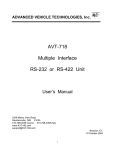
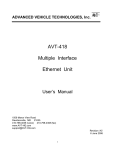
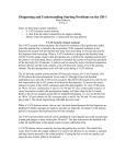
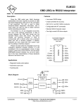
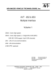
ADVANCED VEHICLE TECHNOLOGIES, Inc. AV inc. AVT-716 MULTIPLE INTERFACE RS-232/422 Unit User’s Manual 1509 Manor View Road Davidsonville, MD 21035 410-798-4038 (voice) 410-798-4308 (fax) Revision B May, 2001 1 TABLE OF CONTENTS 1. INTRODUCTION .........................................................................................................................................................4 1.1 SPECIFICATIONS AND REQUIREMENTS ............................................................................................................................5 1.2 DEFINITIONS ...................................................................................................................................................................5 2. INSTALLATION...........................................................................................................................................................5 2.1 HARDWARE CONFIGURATION .........................................................................................................................................5 2.2 HARDWARE CONNECTIONS ............................................................................................................................................7 2.3 TESTING THE AVT-716 ..................................................................................................................................................7 3. INTERFACE INTRODUCTION .................................................................................................................................8 4. INTERFACE DESCRIPTION .....................................................................................................................................8 5. AVT-716 OPERATION ................................................................................................................................................9 5.1 INDICATORS....................................................................................................................................................................9 5.2 COMMUNICATIONS, ELECTRICAL..................................................................................................................................10 5.3 COMMUNICATIONS, MESSAGES ...................................................................................................................................10 5.3.1 Packet Construction .............................................................................................................................................10 5.4 VPW MODE .................................................................................................................................................................12 5.4.1 Transmit message format .....................................................................................................................................12 5.4.2 Receive message format .......................................................................................................................................12 5.4.3 Received Message Status Byte Definitions...........................................................................................................13 5.4.4 Block Transfer Operations ...................................................................................................................................13 5.4.5 Trigger Function ..................................................................................................................................................13 5.4.6 Examples ..............................................................................................................................................................13 5.5 PWM MODE ................................................................................................................................................................14 5.5.1 ‘Look Alike’ mode ................................................................................................................................................14 5.5.2 Transmit message format ‘Look Alike’ mode Off................................................................................................14 5.5.3 Transmit message format ‘Look Alike’ mode On ................................................................................................15 5.5.4 Receive message format ‘Look Alike’ mode Off..................................................................................................15 5.5.5 Receive message format ‘Look Alike’ mode On ..................................................................................................16 5.5.6 HBCC Initialization Parameters ..........................................................................................................................16 5.5.7 Examples ..............................................................................................................................................................18 5.6 ISO 9141-2 MODE .......................................................................................................................................................19 5.6.1 ISO Operations ....................................................................................................................................................19 5.7 KEYWORD PROTOCOL 2000 MODE ..............................................................................................................................20 5.7.1 KWP Operations ..................................................................................................................................................20 5.7.2 KWP Long Messages............................................................................................................................................20 5.8 ALDL (OR UART) MODE ............................................................................................................................................21 5.8.1 ALDL (or UART) Operations ...............................................................................................................................21 5.9 CCD MODE ..................................................................................................................................................................22 5.9.1 CCD Operations...................................................................................................................................................22 5.10 MATCH FUNCTION......................................................................................................................................................22 5.11 STATUS AND ERROR CODES .......................................................................................................................................23 6. TECHNICAL INFORMATION ................................................................................................................................23 6.1 REFERENCE DOCUMENTATION .....................................................................................................................................23 6.2 TECHNICAL SUPPORT ...................................................................................................................................................23 6.3 AVT-716 MULTIPLE INTERFACE INFORMATION ...........................................................................................................24 6.3.1 Board #1 jumpers JP1 and JP2 ..........................................................................................................................24 6.3.2 Board #2 fuse F1.................................................................................................................................................24 6.3.3 Board #2 jumper JP1 ..........................................................................................................................................24 2 6.3.4 Board #2 jumper JP2, JP3, JP4..........................................................................................................................24 6.3.5 Board #2 connector P1 .......................................................................................................................................25 6.3.6 Board #2 connector P2 .......................................................................................................................................25 6.3.7 Board #2 connector P3 .......................................................................................................................................26 6.3.8 Board #2 connector P4 .......................................................................................................................................26 6.4 AVT-716 ENCLOSURE INFORMATION ..........................................................................................................................26 6.4.1 Enclosure connector P1 ......................................................................................................................................27 6.4.2 Enclosure connector P2 ......................................................................................................................................27 7. COMPANY OVERVIEW...........................................................................................................................................28 FIGURE 1 RS-232 CONNECTOR AND JUMPER CONFIGURATION ..........................................................................................6 FIGURE 2 RS-422 CONNECTOR AND JUMPER CONFIGURATION ..........................................................................................6 FIGURE 3 AVT-716 HARDWARE INTERFACE UNIT BLOCK DIAGRAM ...............................................................................11 TABLE 1 BAUD RATE SELECTION (FIRMWARE V4.9 AND BELOW).......................................................................................7 TABLE 2 BAUD RATE SELECTION (FIRMWARE V5.0 AND ABOVE). ......................................................................................7 3 1. INTRODUCTION This manual covers the AVT-716 Multiple Interface hardware. It provides technical information on using the interface, connections to it, communications with it, and other related information. The AVT-716 Multiple Interface supports the following modes of operation. • J1850 VPW (Variable Pulse Width). • J1850 PWM (Pulse Width Modulation). • ISO 9141-2. • Keyword Protocol 2000 (ISO 14230). • GM’s ALDL or UART (8192 baud). • Chrysler’s CCD. The AVT-716 Ready-To-Use package consists of the AVT-716 Multiple Interface board set housed in an enclosure; the Controller software; a serial cable; an OBD-II compatible cable; and this User’s Manual. The AVT-716 Hardware Only package consists of the AVT-716 Multiple Interface board set housed in an enclosure; a serial cable; an OBD-II compatible cable; and this User’s Manual. The AVT-716 OEM module consists of the AVT-716 Multiple Interface board set only. All connections to the interface board set are identified in Section (6.3). Federal law (and some State laws) require that all 1996 model year and later vehicles be equipped with any one of three network interfaces for connection and communications with off-vehicle test and diagnostic equipment. The three network standards are SAE J1850 VPW, J1850 PWM, and ISO 9141-2. None of these standards are compatible with the others. Operations in J1850 VPW mode is in accordance with the J1850 standard. Additionally, transmit and receive operations are permitted at 4 times the normal rate. This 4X mode of operation may be required for some GM Class 2 operations. (Note that IFR’s with respect to the normalization bit are handled exactly the opposite as is recommended in the J1850 standard. Operations in J1850 PWM mode conforms to the Ford Motor Company Standard Corporate Protocol (SCP). The SCP defines network traffic management, message construction, and other protocol issues. The AVT-716 is fully compatible with any similarly equipped Ford Motor Company or Mazda product. Operations in ISO 9141-2 mode is in accordance with the ISO standard. Operations in Keyword Protocol 2000 is in accordance with ISO standard 14230. The AVT-716 Multiple Interface provides the following functions: • Isolated electrical interface between the subject vehicle and the control computer. • Protocol/data conversion between a vehicle based network and the host computer (via a serial communications link). • Passive network traffic monitor. • Performs all functions of an active SCP qualified network node. 4 If using the AVT Controller or Capture software, please refer to the: “AVT-xxx Controller Software User’s Manual.” Necessary for operation of the AVT-716 Controller software, but not provided, is a PC-AT compatible computer with either an RS-232 or an RS-422 serial port. 1.1 Specifications and Requirements AVT-716 Multiple Interface (in enclosure) • • • • • Overall size (inches): 6.7 wide x 2.2 high x 4.75 deep (5.4 including switch and connectors). Weight: 19 oz. +12 volts (nominal) from subject vehicle. Input voltage range: +8.5vdc to +24vdc. Power dissipation: 1.8 watts (nominal). AVT-716 Multiple Interface (OEM board set) • • • • • Overall size: 4.0 wide x 5.6 deep x 1.5 high (inches). Weight: 7 oz. +12 volts (nominal) from subject vehicle. Input voltage range: +8.5vdc to +24vdc. Power dissipation: 1.8 watts (nominal). 1.2 Definitions The following terms are used in this manual. • KWP2000: Keyword Protocol 2000 (ISO standard 14230). • HBCC: Hosted Bus Controller Chip (Motorola / Ford Motor Company). • SCC: Serial Communications Controller device. • SCP: Standard Corporate Protocol (Ford Motor Company). • DLC: Data Link Controller device (Motorola). • ECU: Electronic Control Unit (e.g. engine controller). • All numbers used in this manual are hexadecimal digits (0 .. 9 and A .. F) and are usually preceded with a dollar sign ($) for clarity. 2. Installation Prior to using the AVT-716 the type and baud rate of the serial link between it and the host computer must be properly set. The interface must then be connected to both the subject vehicle and the control computer. 2.1 Hardware Configuration The AVT-716 serial interface can be configured for either RS-232 or RS-422 operation . Additionally, the data rate can be configured for 9.6k, 19.2k, 38.4k, or 57.6k baud rate. These configuration selections are set by jumpers and connectors on the AVT-716 Multiple Interface board set. (Note: documentation by other manufacturers may make reference to 56k baud. This is usually the same as what we refer to as 57.6k baud.) 5 The factory default settings for the AVT-716 are for RS-232 operation at 9.6k baud rate. Refer to the following instructions and Figures 1 and 2 for details on configuring the AVT-716 serial communications to the host computer. To select RS-232 operation: • Locate jumper JP1 on AVT-716 board #2. Board #2 is the bottom board. • Place the jumper across pins 3 and 5 on JP1. • Place the jumper across pins 4 and 6 on JP1. • Connect the internal serial cable to P1 on AVT-716#2 interface board. (The internal serial cable is a ribbon cable connected to the enclosure mounted connector P2, it’s the narrower of the two cables.) P1 JP1 P2 6 4 2 5 3 1 RS-232 Figure 1 RS-232 Connector and Jumper Configuration To select RS-422 operation: • Locate jumper JP1 on AVT-716 board #2. Board #2 is the bottom board. • Place the jumper across pins 1 and 3 on JP1. • Place the jumper across pins 2 and 4 on JP1. • Connect the internal serial cable to P2 on AVT-716#2 board. (The internal serial cable is a ribbon cable connected to the enclosure mounted connector P2, it’s the narrower of the two cables.) P1 JP1 P2 6 4 2 5 3 1 RS-422 Figure 2 RS-422 Connector and Jumper Configuration To set the baud rate: The baud rate is determined by installing or removing the jumpers on JP1 and JP2 on the AVT-716 board #1. Refer to Table 1 for JP1 and JP2 settings and corresponding baud rates. 6 Baud Rate JP1 JP2 9.6k In In 19.2k Out In 38.4k In Out 57.6k Out Out Table 1 Baud Rate Selection (firmware v4.9 and below). Baud Rate JP1 JP2 19.2k In In 38.4k Out In 57.6k In Out 115.2k Out Out Table 2 Baud Rate Selection (firmware v5.0 and above). 2.2 Hardware Connections Connecting the AVT-716 to the subject vehicle is accomplished via the OBD-II compatible cable available from AVT, Inc. (Note: this cable is not supplied with the OEM module.) The cable has a DA-15S connector on one end and an OBD-II compatible connector on the other end. The DA-15S connector is mated to the DA-15P connector on the AVT-716 enclosure. The other end of the cable is mated to the OBD-II connector in the subject vehicle. (Refer to SAE Standard J1962 for a description of the OBD-II connector and its location in a vehicle.) The AVT-716 interface receives operating power from the subject vehicle through this cable as well as power and signal grounds. Additionally, the cable provides the network connections between the interface and the subject vehicle. The AVT-716 interface is connected to the control computer via the supplied 9 pin cable. (Note: this cable is not supplied with the AVT-716 OEM module.) The cable is compatible with a PC-AT standard 9 pin RS-232 connection. We cannot guarantee it, but direct connection of the AVT-716 interface enclosure to a PC-AT 9 pin RS-232 connection using this cable (or any straight through wired cable) should work without requiring any adapters. No other connections or installation is required. 2.3 Testing the AVT-716 Once the hardware connections have been made, proper operation of the hardware can be observed. • Launch the AVT-716 Controller software or a similar communications program. Note that the AVT-716 communicates with the host computer using binary bytes (not ASCII digits). • Set the parameters of the communications program appropriately (as determined by the configuration of the AVT-716 interface). 7 • • • • • Turn on the AVT-716 interface unit. Observe on the AVT-716#1 interface board (top) that the green (power) LED is lit. Observe that the red (operations) LED is blinking fast. Observe on the computer that the following is received from the interface: 91 07. This is the ‘mode of operation’ report. $91 indicates that the message is a ‘board status report’ with one byte to follow. The $07 indicates VPW mode of operation. Refer to Sections 5.4, 5.5, and 5.6 for AVT-716 commands and responses. Note: The Controller software only displays and accepts hex digits, no dollar signs. At this point the AVT-716 hardware is operational. 3. Interface Introduction The AVT-716 Multiple Interface is available housed in a rugged polycarbonate enclosure with internal cable assemblies and power switch. The two connectors on the enclosure are to the subject vehicle and the control computer. The interface provides an isolated electrical interface between the control computer and the vehicle. The AVT-716 Interface is connected directly to the vehicle and derives its operating power from the vehicle. The serial interface to the control computer is electrically isolated from the vehicle electrical and electronic systems. This is done to prevent damage to the control computer due to spikes or surges from the vehicle electrical system. It is not recommended that the control computer be connected directly to the vehicle electrical system. The AVT-716 Multiple Interface performs the data and protocol conversion functions. When in VPW mode of operation a Motorola DLC device is utilized. When in PWM mode of operation a Motorola HBCC device is utilized. ISO 9141-2 and KWP2000 operations are supported by a custom transceiver design. GM’s ALDL (or UART) operations are at 8192 baud and are supported by a custom transceiver design. Chrysler’s CCD operations are supported by a Harris device. All firmware on the AVT-716 Multiple Interface was developed by and is supported by Advanced Vehicle Technologies, Inc. The serial communications function is provided by a Philips Serial Communications Controller (SCC) device. The RS-232 and RS-422 line drivers and receivers are contained in an electrically isolated section of the AVT-716 #2 board. Signals are coupled through optical isolators and power is supplied by an isolated DC-DC converter. The AVT-716 Multiple Interface utilizes a Motorola CPU32 core microcontroller. All firmware is contained in an EPROM device mounted on AVT-716 board #1. The board set was designed to support the three modes of operation: VPW, PWM, and ISO 9141-2. The selection of operational mode is determined by a software command from the control computer to the Multiple Interface unit. Refer to Section 5.x for detailed information on operations in each of the supported modes. 4. Interface Description A block diagram of the AVT-716 Multiple Interface is shown in Figure 3. The heart of the unit is the Motorola 68332 microcontroller. This device utilizes a 68000 core with a bus speed of 16.777 8 MHz. Operation firmware is contained in an EPROM. Software commands from the control computer control the selection of the operational mode of the interface. The microcontroller utilizes several peripheral devices: two FIFO’s each 2 KBytes deep, a DLC device, an HBCC device, a serial communications controller, a real time clock, and a millisecond resolution free running timer. The two FIFO’s are used by the microcontroller as buffers for the transmit and receive operations between itself and the control computer. A serial communications controller is used to implement the standard serial data link, including RTS/CTS hardware handshaking. The serial communications controller is interfaced to the control computer through a signal isolation block and either an RS-232 or an RS-422 transceiver block. The control computer serial data link is electrically isolated from the rest of the Interface unit and, hence, the vehicle through an isolated DC-to-DC power converter and a signal isolation block. DLC device implements the J1850 VPW standard. The HBCC device implements the J1850 PWM standard. A custom design is used for the implementation of the ISO 9141-2 and KWP2000 standard. A Harris “serial multiplexed bus interface device” is used to implement the CCD mode of operation. A battery backed real time clock is available on the board as well as a free running timer with millisecond accuracy. Also available on the board is 8 KBytes of additional RAM (available for future growth). The on-board real time clock is not Year 2000 compliant. It reports the year in two digits. However, the AVT-716 does not utilize the day/date information for operations. Testing has demonstrated that the AVT-716 continues to operate without interruption when the year rolls over from 1999 to 2000. 5. AVT-716 Operation The following describes the use of the AVT-716 Multiple Interface. It is assumed that the interface is properly connected to the subject vehicle and to the control computer. Furthermore, it is assumed that the AVT-716 Controller software (or similar communications software) has been installed on the control computer, that it is running, and that the test described in Section 2.3 has been completed successfully. 5.1 Indicators The AVT-716 board #1 has two indicator LED’s: one green and one red. The green LED is connected to the +5 VDC supply for the board and provides a quick indication that power is available for normal operation. If the green LED should fail to light, check the power source from the subject vehicle, and check fuse F1 on the AVT-716 board #2. The red LED is a heartbeat indicator. The microcontroller toggles the state of the red LED every 62.5 milliseconds. As a result the red LED flashes noticeably during normal operations. If a problem with the microcontroller should occur the LED will either go to a full ON or full OFF state. This should be readily apparent and be indicative of an abnormal condition. 9 5.2 Communications, Electrical All communications between the interface and the subject vehicle are in conformance with SAE Standard J1850 and all related standards and recommended practices. When in the PWM mode of operation, the interface is compliant with the Ford SCP. Operations in ISO mode are compliant with ISO specification ISO 9141-2. All communications between the AVT-716 Multiple Interface and the control computer conform, at the physical interface, to either EIA-RS-232 or RS-422 standards (as selected by the user). Communications between the interface unit and the control computer follow industry standard serial communications protocol. There is one start bit, eight data bits (least significant bit first), no parity, and one stop bit. Additionally, hardware handshaking using the RTS/CTS signal lines is used. When in RS-232 mode the output data line, TXD, idles low (-8 volts) and the RTS signal line idles high (+8 volts). Likewise, the AVT-716 expects RXD to idle low and CTS to idle high. (All voltages measured with respect to the communications isolated ground.) The user should be aware of potential communications errors that may occur when using RS-232 at the higher data rates or in an electrically noisy environment. When in RS-422 mode the output data lines idle such that TXD+ is high (+4 volts) and TXD- is low (0 volts). The RTS+ signal idles low (0 volts) and RTS- is high (+4 volts). Likewise the AVT-716 expects RXD+ to idle high (RXD- is low) and CTS+ is low (CTS- is high). (All voltages measured with respect to the communications isolated ground.) 5.3 Communications, Messages The structure and protocol of communications between the control computer and the interface are stated in the following sections. 5.3.1 Packet Construction Messages from the host computer to the AVT-716 Interface are known as Commands. Message from the AVT-716 Interface to the host computer are known as Responses. All data is transferred in packets. The size of each data packet varies depending on the mode of operation. For most modes the packet length is from 1 byte to 16 bytes (inclusive). The first byte in each data packet is the header byte and is used to convey information only between the control computer and the microcontroller in the interface. The header byte is divided into the upper nibble and lower nibble. The upper nibble indicates what information the data packet is conveying. The lower nibble is the count of the number of bytes that follow the header byte. The meaning of the upper nibble of the header byte depends on which direction the data packet is moving; whether to or from the control computer. Both KWP2000 and ALDL (or UART) modes of operation support long and very long packet lengths. These packets may be as long as 259 bytes. For packets of this length an alternate form of packet construction is used. 10 EPROM Program Memory Heart Beat LED (red) Power LED (green) Power Regulation & Distribution I/O Ports Control and monitor signals DLC-S (VPW Interface) MC68332 Microcontroller HBCC (PWM Interface) To Vehicle Transient Protection Switch PWM Transceiver Batt + Bus + Switch Switch Bus - K - line Transceiver Switch K-line L - line Transmitter Switch L-line FIFO #1 FIFO #2 To Control Computer RS-232 Transceivers RS-422 Transceivers Signal Isolation and Selection Dual Serial Communications Controller logic Sig. Isolated DC - DC Power Source Chassis Figure 3 AVT-716 Hardware Interface Unit Block Diagram 11 5.4 VPW Mode Consult the latest version of the “Commands and Responses” list for detailed information on the commands supported by the AVT-716 while in VPW mode of operation. The latest version of the “Commands and Responses” document can be obtained from our web site at: http://www.avt-hq.com When in VPW mode of operation the interface is always listening to, or monitoring, the J1850 bus. All bus traffic is reported to the control computer by the interface. Transmit operations occur only when initiated by the control computer. 5.4.1 Transmit message format To transmit a message onto the network the message must be built by the operator and then sent to the AVT-716. The CRC byte will automatically be calculated and appended onto the message when transmitted. It is up to the user to determine and know the proper protocol that is implemented on the vehicle to which the AVT-716 is attached. Any message destined for transmission must be preceded by a byte whose upper nibble is ‘0’ (zero) and lower nibble is the byte count of the message. The message bytes then follow immediately. Once a message is accepted by the AVT-716 interface for transmission the proper transmit CRC byte is appended and transmission of the message commences as soon as possible. (J1850 requires that a minimum IFS [Inter-Frame Separation] time interval has elapsed on the bus before any node may begin transmission of a new message.) If, while attempting to transmit a message, the message loses arbitration the winning received message will have the ‘lost arbitration’ bit set in the received status byte. (Refer to Section 5.4.6 for more details on the received message status byte.) If the message is properly transmitted a received message status byte is sent to the control computer. The transmitted message echo is received by the interface but is not sent to the control computer (unless requested by the 5x 06 command). (Example: a message is sent to the interface for transmission, at some later time the interface will report: $01 $60 which indicates that the message was transmitted correctly and that the message was received from itself.) 5.4.2 Receive message format Messages received from the network are assembled into the original byte sequence. The received CRC is calculated and checked to be equal to $C4. Both transmitted and received CRC bytes are then discarded. A received message status byte is constructed and prepended onto the message. A header byte is then prepended onto the message (ahead of the received status byte). This byte sequence is then sent to the host computer. 12 As an example the byte sequence $A7 $B6 $C5 plus CRC byte is transmitted by a node. The transmitted message is received by the interface and the following byte sequence is passed to the control computer: $04 $00 $A7 $B6 $C5. The byte $04 indicates that it is a received message and that four bytes follow. The byte $00 is the received message status byte and indicates that no errors were found. (Received message status byte, bit definitions are listed in the next section.) The message bytes then follow. Note that the CRC bytes are stripped off. 5.4.3 Received Message Status Byte Definitions The received message status byte always follows the header byte, even if the status byte is the result of transmitting a message. Bit 0: 1: 2: 3: 4: 5: 6: 7: Definition CRC error. Incomplete message (incorrect number of bits). Break received. IFR data. Lost arbitration. Transmission successful. From this device. Bad message (message too short or too long). 5.4.4 Block Transfer Operations VPW mode of operation supports both 4x and block transfer modes of operation. Both of these modes are unique to GM and may be required for some operations. Consult the manual supplement “Block Data Transfer” for additional information on how to use the AVT-716 in block transfer mode. 5.4.5 Trigger Function Available only in VPW mode is an external hardware trigger function. Consult the document “AVT-716 - Trigger Function” for detailed information on how to use this capability. 5.4.6 Examples To illustrate the construction and decoding of messages between the control computer and the AVT-716 interface several examples are provided. Example #1: Want to request the current operational mode. Command string: D0. The interface responds with: 91 07. The ‘9’ indicates a board response, the ‘1’ indicates one byte follows, and the 07 indicates VPW mode (Motorola device). 13 Example #2: want to send a message out on the bus. Command string: 04 32 89 AC 5F. The interface responds with: 01 60. The ‘0’ indicates a received message and the ‘1’ indicates only one byte, which is the received message status byte. The ‘60’ indicates that bits 6 and 5 are set which means the received message was from this device and the transmission was successful. (Messages transmitted by the interface are received by the interface, are checked for errors, but are not echoed back to the controller. Only a status byte is passed to the controller to indicate the status of the transmitted message.) 5.5 PWM Mode Consult the latest version of the “Commands and Responses” list for detailed information on the commands supported by the AVT-716 while in PWM mode of operation. The latest version of the “Commands and Responses” document can be obtained from our web site at: http://www.avt-hq.com Operations in PWM mode are different from VPW mode. When operating in PWM mode the HBCC device must be initialized for proper operation, including a unique node address. The HBCC is initialized automatically by the microcontroller, in the interface when powered up or reset. Refer to Section 5.5.8 for a listing of the initialization parameters for the HBCC device. These parameters may be changed by the user from the control computer. When in PWM mode of operation the HBCC device performs input message filtering. Therefore only bus traffic that is destined for the address of the interface is passed to the control computer and displayed. To view all bus traffic while in PWM mode, the HBCC device can be placed into monitor mode by the control computer (via a software command). When in this mode the AVT716 interface becomes a passive PWM network monitor and will not permit transmissions. 5.5.1 ‘Look Alike’ mode The AVT-716 utilizes two different devices and methods of interfacing to the two J1850 buses (VPW and PWM). As a result, messages transmitted and received when in PWM mode are different than if the same message was transmitted or received in VPW mode. Therefore, a ‘Look Alike’ mode was developed for use while in PWM operations. This mode is defaulted to the Off state (to be compatible with previous versions of the AVT-715 unit). When ‘Look Alike’ mode is enabled, the construction of a message is such that it ‘looks’ like its VPW counterpart. Each of the following sections describes message construction when ‘Look Alike’ is enabled (on) or disabled (off). 5.5.2 Transmit message format ‘Look Alike’ mode Off To transmit a message onto the network the message must be built and then passed to the AVT-716 interface. The HBCC (internal to the AVT-716) will automatically insert the source address and append the CRC. All messages destined for transmission onto the network must be constructed as indicated here. All packets for transmission must have a byte count from 2 to 9 (inclusive). Therefore the header 14 byte will have a value of $02 to $09 (inclusive). The bytes following the header byte must be in the following form. Byte 00: 01: Description Header byte Priority/Type 02: 03 - 09: Target ID Data bytes lower nibble is byte count to follow. Priority: 0 - F / Type: 0 - 4 (message type 5 is not implemented as an automatic transmit feature) $00 - $FF (optional, 0 to 7 data bytes depending on message type) 5.5.3 Transmit message format ‘Look Alike’ mode On To transmit a message onto the network the message must be built and then passed to the AVT716 interface. The HBCC (internal to the AVT-716) will automatically append the CRC. All messages destined for transmission onto the network must be constructed as indicated here. All packets for transmission must have a byte count from 3 to 10 (inclusive). Therefore the header byte will have a value of $03 to $0A (inclusive). The bytes following the header byte must be in the following form. Byte 00: 01: Description Header byte Priority/Type 02: 03: 04 - 0A: Target ID Source ID Data bytes lower nibble is byte count to follow. Priority: 0 - F / Type: 0 - 4 (message type 5 is not implemented as an automatic transmit feature) $00 - $FF (e.g. a scan tool would be $F1). (optional, 0 to 7 data bytes depending on message type) An additional function of the ‘Look Alike’ mode is to check the Priority/Type byte. If this byte has a value of $68 then its value is changed to $61. Next bit #3 is of the Priority/Type byte is cleared. (These changes are useful when viewed in the context of OBD-II standardized messages. Please refer to SAE documents J1979 and J2178 for more details.) 5.5.4 Receive message format ‘Look Alike’ mode Off Messages received from the network are assembled into a packet by the AVT-716 interface and then passed to the control computer. These messages will have the following form and will have a byte count less than or equal to $0D. 15 Byte 00: 01: Description Header byte Message number 02: 03: 04: 05 to n-1 n (n <= $D) Priority/Type Target Specifier Source Address Data bytes CRC lower nibble is byte count to follow. according to FMLT order $00: node to node $FF: network monitor 5.5.5 Receive message format ‘Look Alike’ mode On Messages received from the network are assembled into a packet by the AVT-716 interface and then passed to the control computer. These messages will have the following form and will have a byte count less than or equal to $0C. With ‘Look Alike’ mode enabled the CRC byte is dropped when the message is forwarded to the host. Byte 00: 01: Description Header byte Message number 02: 03: 04: 05 to n (n <= $C) Priority/Type Target Specifier Source Address Data bytes lower nibble is byte count to follow. according to FMLT order $00: node to node $FF: network monitor 5.5.6 HBCC Initialization Parameters When the AVT-716 interface is powered up, the HBCC device is initialized and a local loopback test is conducted. If the local loopback test passes successfully, the HBCC device operational parameters are then set to default parameters and the HBCC network drivers are enabled. In the event the HBCC local loopback test fails for any reason an error code is passed to the control computer and the HBCC network drivers are disabled. Most HBCC registers and RAM locations are set to default values during PWM mode initialization. The following is a list of these registers and RAM locations along a brief explanation of the initialization status and the value written to each location. The user should consult the HBCC User’s Guide for detailed information on each of the registers, RAM, and individual bit definitions. 16 Name Address Default Value UIMR User Interrupt Mask Register RCR Receive Control Register Register $07 $FF All user interrupt disabled Register $01 $04 HCR HBCC Control Register Register $02 $72 TCR Transmit Control Register NAR Node Address Register FMLT Function Message Lookup Table Register $00 $0x Register $10 $F1 Receive OK interrupt mask Receive error interrupt mask Receiver overrun interrupt mask Unable to acknowledge interrupt mask Network fault interrupt mask Enable network driver A Enable network driver B 41.6 kbps never sleep Transmit OK interrupt mask Transmit error interrupt mask Critical transmit error interrupt mask OBD-II diagnostic tool address RAM $10 $5A OBD-II diagnostic message. RAM $11 RAM $12 RAM $13 RAM $14 $5B OBD-II diagnostic message. $6A OBD-II diagnostic message. $6B OBD-II diagnostic message. FRMLT Function Read Message Lookup Table FRDR1 Function Read Data Register #1 FRDR2 Function Read Data Register #2 RAM $15 Register $08 Register $09 Description $04 $06 $B2 $B4 17 Name FRDR3 Function Read Data Register #3 FRMLTP Function Read Message Lookup Table Pointer SUR Start of User’s RAM Address Default Value Register $0A $B6 Register $11 $14 Register $12 $16 Description 5.5.7 Examples To illustrate the construction and decoding of messages between the control computer and the AVT-716 interface several examples are shown for illustration. Example #1: Want to write a byte to a register in the HBCC device. Command string: 83 01 02 16. Explanation: header byte 83, 8 is the command for HBCC functions, 3 is the number of bytes to follow. 01 is the write HBCC register command. 02 is the register address. 16 is the value of the byte to be written into HBCC register at address 02. (This is the command to put the HBCC device into the network monitor mode.) Example #2: Want to make an OBD-II engine temperature query with ‘Look Alike’ off. Command string: 04 61 6A 01 05. Explanation: header byte 04, 0 indicates that the following bytes are for transmission onto the network by the HBCC and 4 indicates that 4 bytes follow. 61 indicates a priority 6 message of type 1 (broadcast). 6A indicates that the message is only destined to those nodes that recognize function 6A messages (diagnostic message). The last two bytes ‘01’ and ‘05’ are the actual message data bytes (mode 1 PID 5; refer to SAE J1979 for more information). Example #3: Want to make an OBD-II engine temperature query with ‘Look Alike’ on. Command string: 05 68 6A F1 01 05. Explanation: header byte 05, 0 indicates that the following bytes are for transmission onto the network by the HBCC and 5 indicates that 5 bytes follow. 68 indicates a priority 6 message and type 8 (with ‘Look Alike’ on this byte is replaced with $61). F1 is the source ID. 6A indicates that the message is only destined to those nodes that recognize function 6A messages (diagnostic message). The last two bytes ‘01’ and ‘05’ are the actual message data bytes (mode 1 PID 5; refer to SAE J1979 for more information). Example #4: Send the message of example #2 and receive the response: 22 09 40. Explanation: header byte 22, 2 indicates HBCC error, 2 indicates that two bytes follow. 09 is the error code for the HBCC and indicates that an interrupt register 2 (IR2) error occurred. The last byte is the contents of IR2. A value of 40 in IR2 indicates that a transmit error limit expired. 18 This error indicates that no node responded with confirmation of reception of the message (no node answered). Example #5: Send the message of example #2 and receive the response: 41 C4. Explanation: header byte 41, 4 indicates that the message was transmitted OK (at least one node responded) and the 1 indicates one byte follows. The byte C4 is the address of the node that responded to the transmitted message (node C4 responded affirmatively to receipt of the transmitted message). 5.6 ISO 9141-2 Mode Consult the latest version of the “Commands and Responses” list for detailed information on the commands supported by the AVT-716 while in ISO 9141-2 mode of operation. The latest version of the “Commands and Responses” document can be obtained from our web site at: http://www.avt-hq.com 5.6.1 ISO Operations The transmission and reception of messages while in ISO mode is very similar to operations while in VPW mode; once communications with the vehicle have been initialized successfully. When in ISO mode there are several unique operational requirements. The user should consult the ANSI/ISO specification for operational details. Some of these are listed here. • Before communications can be conducted between the AVT-716 and the vehicle ECU an initialization sequence must be successfully completed. This is accomplished via the $61 $02 command. If initialization is successful the AVT-716 will respond with $71 $03. • Once initialization has been completed successfully communications between the AVT-716 and the ECU must be maintained. If more than 5 seconds passes without the AVT-716 transmitting a message the ECU will assume the tester is no longer present. Further communications will require that the communications link be reinitialized. • To maintain communications following successful initialization, the AVT-716 will automatically transmit a “keep alive” message to the vehicle every 4 seconds, if another message is not transmitted first (as initiated by the control computer). The default “keep alive” message is a mode 1 PID 0 diagnostic request. The “keep alive” message can be changed or deleted by the user through the $5x $04 and $51 $05 commands. Operations are permitted that do not require successful initialization. This operational mode is obtained via the $61 $04 command. Using that command and the $53 $03 $xx $yy command the AVT-716 can be connected to the ISO bus K-line, communications on the line can be monitored and messages transmitted. This mode omits or bypasses some ISO 9141-2 communications requirements. When operating in this mode the user is cautioned to be aware. 19 When operating in the non-initialized mode ($61 $04) the baud rate of communications is defaulted to be 10.4 kbps (bits per second). This baud rate can be changed by the user through the $53 $03 $xx $yy command. The bytes $xx and $yy are the upper and lower bytes, respectively, of a timer load. This number can be calculated according to the following formula. The default timer load is $00 $0B for a default baud rate of 10.4 kbps. Timer _ Load = 3.6864 • 106 2 • 16 • Baud _ Rate 5.7 Keyword Protocol 2000 Mode Consult the latest version of the “Commands and Responses” list for detailed information on the commands supported by the AVT-716 while in KWP mode of operation. The latest version of the “Commands and Responses” document can be obtained from our web site at: http://www.avt-hq.com 5.7.1 KWP Operations Operation in KWP mode is nearly identical to that in ISO 9141-2 mode. The big differences are that communications initialization can be accomplished via any of three ways: CARB, 5-Baud, and Fast Initialization. The user is recommended to consult the ISO 14230 specification for detailed information on these modes of initialization. Consult the document “Keyword Protocol 2000 Initialization” for detailed information on the initialization sequence for each type of initialization supported by the AVT-716. Also consult the document “AVT-716 - KeyWord Protocol 2000 Mode” for a discussion of how to use the AVT-716 in a KWP2000 environment. 5.7.2 KWP Long Messages The KeyWord Protocol 2000 specification supports messages with as many as 255 bytes of data. To accommodate these long messages, the format for communications between the AVT-716 unit and the host computer has been modified. To send a message onto the bus the host has a choice of how to send the message to the 716 unit. These are described here, along with examples. Remember that the AVT-716 unit will automatically compute and append the checksum byte. If the message is 15 bytes or less in length (total) then the 'normal' format may be used. Normal Format: 0x aa bb cc ... x - count of bytes to follow aa bb cc ... message bytes. Example: 05 81 F1 C1 48 9B 20 If the message is more than 15 bytes but less than 255 bytes in length, alternate format #1 is available using a header byte of $11. Alternate format #1: 11 xx aa bb cc ... 11 - header byte xx - count of bytes to follow aa bb cc ... message bytes. If the message is more than 255 bytes in length, alternate format #2 is available using a header byte of $12. Alternate format #2: 12 xx yy aa bb cc ... 12 - header byte xx - count of bytes to follow, most significant byte yy - count of bytes to follow, least significant byte aa bb cc ... message bytes. These formats are backward compatible and may be used as desired. For example, the host wants to transmit the following message onto the bus: A1 B2 C3 D4 E5 F6 A7 B8 C9 DA EB FC AD BE The following messages from the host to the AVT-716 are all equivalent. The header byte(s) have been bolded and underlined for clarity. 0E A1 B2 C3 D4 E5 F6 A7 B8 C9 DA EB FC AD BE 11 0E A1 B2 C3 D4 E5 F6 A7 B8 C9 DA EB FC AD BE 12 00 0E A1 B2 C3 D4 E5 F6 A7 B8 C9 DA EB FC AD BE 5.8 ALDL (or UART) Mode Consult the latest version of the “Commands and Responses” list for detailed information on the commands supported by the AVT-716 while in ALDL (or UART) mode of operation. The latest version of the “Commands and Responses” document can be obtained from our web site at: http://www.avt-hq.com 5.8.1 ALDL (or UART) Operations Operations in ALDL (or UART) mode are similar to that of VPW mode. The user is cautioned that they must have detailed knowledge of how to properly construct a message when in this mode. If a message is improperly constructed for transmission erratic operations may result. Consult the document “AVT-716 - 8192 UART Mode” for a discussion of using the AVT-716 in ALDL (or UART) mode. Note that ALDL mode also supports messages longer than 16 bytes. To support this, the same format as that used to support long KWP messages is used here. Consult Section 5.7.2 for detailed information on these formats. 21 5.9 CCD Mode Consult the latest version of the “Commands and Responses” list for detailed information on the commands supported by the AVT-716 while in CCD mode of operation. The latest version of the “Commands and Responses” document can be obtained from our web site at: http://www.avt-hq.com 5.9.1 CCD Operations Operations in CCD mode are similar to that of VPW mode. 5.10 Match Function A coarse filtering mechanism for messages received from the bus is provided by the AVT-716 Interface unit firmware. If the match table is cleared (on power-up, reset, or $31 $7B command) all messages received from the network are passed to the host. When at least one entry is made to the match table, all messages received from the network are checked against the match table. If a match is found the message is passed to the host. If no match is found, the message is discarded, and the host is not notified. A match table entry is made using the $32 $xx $yy command. The $xx value is the byte position and the $yy value is the byte value. This filtering mechanism is more easily explained by example. It is desired to receive all messages (at the host) where the third byte of the message is equal to $F1. Send the command $32 $03 $F1 to the AVT-716 interface. To verify the table entry send the command $30. The response will be $42 $03 $F1. The only network messages passed to the host will now be of the form: $zz $xx $F1 $... Note that at the host the message will be $rr $ss $zz $xx $F1 $.. where $rr is the header byte, $ss is the received message status byte, and the message follows. The match table can hold ten entries where an entry consists of a byte position and a byte value. The byte position refers to where in the network message the match byte is to be compared. The first byte of the message has a byte position value of one. Ordering of the match table is not important. All table entries are checked until a match is found or the end of the table is encountered. If a match table entry specifies a byte position that doesn’t exist for the message being checked (the message is shorter than the table entry), that table entry is not checked. Note that the header byte and the received message status byte are not included in the match function nor are these two bytes considered part of the message. When in VPW and ISO modes the byte following the header byte is the received message status byte. When in PWM mode the byte following the header byte is the message number. These bytes are ignored by the match function and are not counted. The very next byte is the first byte of the message and has is byte number one of the message. 22 5.11 Status and Error Codes Consult the latest version of the “Commands and Responses” list for a complete list of Status and Error codes supported by the AVT-716. The latest version of the “Commands and Responses” document can be obtained from our web site at: http://www.avt-hq.com 6. Technical Information 6.1 Reference Documentation This section contains reference information on the J1850 specification, the HBCC device, the Standard Corporate Protocol, and related technical information. These documents should be consulted for additional or detailed information. 1. SAE Standard J1850 “Class B Data Communications Network Interface.” Available from the SAE, 400 Commonwealth Drive, Warrendale, PA 15096-0001; phone: 412-776-4970. 2. ISO standard 9141-2 “Road Vehicles - Diagnostic Systems - Part 2.” (1994-02-01). 3. Ford Motor Company “Hosted Bus Controller Chip User’s Guide.” 4. Ford Motor Company “SCP Protocol Definition and Interface Requirements.” Document number: ES-F7LC-12K529-BA. 5. Ford Motor Company “SCP Diagnostic Message and Dialogue Requirements.” Document number: ES-F7LC-12K529-CA. 6. Automotive Multiplexing Technology. Papers from the 1995 SAE World Congress. SAE publication SP-1070. Papers from the 1996 SAE World Congress. SAE publication SP-1137 Papers from the 1997 SAE World Congress. SAE publication SP-1224 Available from the SAE, 400 Commonwealth Drive, Warrendale, PA 15096-0001; phone: 412-776-4970. 6.2 Technical Support The user may contact Advanced Vehicle Technologies, Inc. for assistance in any of the areas covered here. When calling please be prepared to identify yourself and tell us the serial number of your hardware. Advanced Vehicle Technologies, Inc. is located in Maryland and is open from 0800 hrs. to 1800 hrs. Eastern Time. If calling after hours, please leave a message and we will return your call as quickly as possible. You may also fax your questions to us. We will either fax an answer back or call you, at your request. If faxing your question, please include as much relevant information about your question or problem as you can. 23 We can be contacted: Voice: Fax: or by E-mail at: 410-798-4038 410-798-4308 [email protected] 6.3 AVT-716 Multiple Interface Information Information about the enclosure is contained in Section 6.4. The following sections contain information about the AVT-716 Multiple Interface board set. The board set consists of two boards, AVT-716#1 is the top board and AVT-716#2 is the bottom board. Board #1 contains the microcontroller, memory, UART, real time clock, and millisecond timer. Board #2 contains the hardware to support the various interfaces. 6.3.1 Board #1 jumpers JP1 and JP2 JP1 and JP2 on the AVT-716#1 board are used to select the serial communications port baud rate. Set the jumpers for the desired baud rate in accordance with the instructions in Section 2.1. 6.3.2 Board #2 fuse F1 Fuse F1 on the AVT-716#2 board is a 500 milliamp fast blow fuse designed to protect the AVT716 in the event of reverse voltage application or a voltage surge significant enough to trip the input transient voltage suppressor. The fuse is a Schurter # MSF 125 034.4216. 6.3.3 Board #2 jumper JP1 JP1 on the AVT-716#2 board is used to select which serial communications port is active, RS232 or RS-422. The jumpers on JP1 should be set as noted in Section 2.1. 6.3.4 Board #2 jumper JP2, JP3, JP4 These jumpers are related to the CCD bus. (They are installed at the factory.) JP2 - Pulls the CCD+ bus down to ground through a 12.1 Kohm resistor. JP3 - Connects across the CCD+ and CCD- bus lines through a 200 ohm resistor. JP4 - Pulls the CCD- bus up to +5v through a 12.1 Kohm resistor. 24 6.3.5 Board #2 connector P1 P1 on the AVT-716#2 board is the RS-232 serial port connection. The connector is a 10 position header with pins on 0.100 inch centers. The header is compatible with an AMP #111917-1 a 10 position IDC ribbon cable connector. Only the indicated pins are connected, all others are ‘not connected.’ Pin Number 1 2 3 4 5 6 7 9 Name CD TXD CTS RXD RTS Sig. Gnd. +5v (via a 10K ohm resistor) output connected to pin #7 (for DTR/DSR loop) Transmit Data output Clear To Send input Receive Data input Ready To Send output connected to pin #2 (for DTR/DSR loop) Isolated from vehicle ground 6.3.6 Board #2 connector P2 P2 on the AVT-716#2 board is the RS-422 serial port connection. The connector is a 10 position header with pins on 0.100 inch centers. The header is compatible with an AMP #111917-1 a 10 position IDC connector. Only the indicated pins are connected, all others are ‘not connected.’ Pin Number Name Function / Description 1 2 3 4 5 6 7 8 9 Sig. Gnd. RTS CTS + RTS + CTS TXD + RXD + TXD RXD - Isolated from vehicle ground Ready To Send (inverted) Clear To Send Ready To Send Clear To Send (inverted) Transmit data Receive data Transmit data (inverted) Receive data (inverted) 25 output input output input output input output input 6.3.7 Board #2 connector P3 P3 on the AVT-716#2 board is the connection to the vehicle’s OBD-II port. The connector is a 16 position header with pins on 0.100 inch centers. The header is compatible with an AMP #111918-3 a 16 position IDC connector. Only the indicated pins are connected, all others are ‘not connected.’ Pin # 2 3 4 5 6 7 9 10 13 14 Signal ALDL (8192 UART) J1850 Bus + J1850 Bus CCD+ CCDGround (chassis) Ground (signal) External power (+12v nominal). ISO 9141 K-line ISO 9141 L-line 6.3.8 Board #2 connector P4 P4 on the AVT-716#2 board enables or disables the high side supply voltage to the entire AVT-716 Multiple Interface board set. It is a 2 position header with pins on 0.100 inch centers and is compatible with AMP #640441-2 2 position IDC connector. When the interface board set is installed in the supplied enclosure, P4 is connected to the front panel toggle switch. When the AVT-716 is delivered as an OEM module P4 has a jumper installed. 6.4 AVT-716 Enclosure Information The following sections contain information about the AVT-716 Multiple Interface board set mounted in the provided enclosure. The AVT-716 board set is available mounted in a rugged polycarbonate enclosure. Also included in the enclosure are two internal cable assemblies and a locking toggle switch for unit power. 26 6.4.1 Enclosure connector P1 Connector P1 on the AVT-716 enclosure is a DA-15P connector and will mate to any industry standard DA-15S connector. It is connected to the subject vehicle OBD-II connector through the supplied cable assembly. Only the signal lines that the AVT-716 Multiple Interface uses are indicated here. In accordance with the standard there may be other signals on the OBD-II connector in the vehicle. The AVT-716 does not connect to or utilize signals or lines other than those indicated here. All other pins on this connector are ‘not connected.’ Pin # 2 3 4 5 7 9 10 11 13 15 Signal J1850 Bus + CCD+ Ground (chassis) Ground (signal) ISO 9141 K-line ALDL (8192 UART) J1850 Bus CCDExternal power (+12v nominal). ISO 9141 L-line 6.4.2 Enclosure connector P2 Connector P2 on the AVT-716 enclosure is a DE-9S connector and will mate to any industry standard DE-9P connector. Depending on the configuration of the AVT-716 interface, this connector is either an RS-232 or an RS-422 communications port. Through this connection the control computer communicates with the AVT-716 Multiple Interface and, hence, the subject vehicle. Hardware handshaking (RTS/CTS) is required for proper operation of the AVT-716 Multiple Interface. All signals and directions indicated are relative to the AVT-716 interface. RS-232 Configuration Pin Number Name Function / Description 1 2 3 4 5 6 7 8 9 CD TXD RXD DTR Sig. Gnd. DSR CTS RTS RI +5v Transmit Data Receive Data connected to DSR, pin #6 Isolated from vehicle ground connected to DTR, pin #4 Clear To Send Ready To Send not used 27 output output input input output RS-422 Configuration Pin Number Name Function / Description 1 2 3 4 5 6 7 8 9 Sig. Gnd. CTS + CTS RXD + RXD RTS RTS + TXD + TXD - Isolated from vehicle ground Clear To Send Clear To Send (inverted) Receive data Receive data (inverted) Ready To Send (inverted) Ready To Send Transmit data Transmit data (inverted) input input input input output output output output 7. Company Overview Advanced Vehicle Technologies, Inc. is dedicated to providing affordable hardware, software, and technical support to the developers and users of vehicle based networks. AVT, Inc. also offers other vehicle network products including: • AVT-1850-1 J1850 VPW Development System • AVT-715 Dual J1850 Interface (RS-232/422 unit) • AVT-921 Dual J1850 Interface (an 8-bit ISA board). • AVT-931 Dual J1850 Interface (PC/104 form factor). Contact the factory for information on these products and our latest offerings. The engineering staff at AVT, Inc. is experienced with multiplex bus standards including: J1850 VPW and PWM and ISO-9141 and 9141-2. Members of the staff are available to provide assistance on the use of any of AVT’s products. AVT engineering staff members are available to provide dedicated engineering support for a customer project. Through a simple contractual arrangement, a customer is able to ‘tap’ into AVT’s knowledge and experience base. Information on any of the products or engineering support that Advanced Vehicle Technologies can provide is available by calling, faxing, or writing. Advanced Vehicle Technologies, Inc. 1509 Manor View Road, Davidsonville, MD 410-798-4038 (voice) 410-798-4308 (fax) Home Page: http://www.avt-hq.com e-mail: [email protected] 28 21035 Revision Record: A1: Original release. A2: Added a couple of new error messages. Made several minor corrections to the document formatting. A3: Corrected pin assignments for P3 on Board #2, Section 6.3.6. Corrected technical support phone numbers. Corrected spelling of the word “Coarse.” B1: Major revision to reflect the rev. “E” hardware. Rev. “E” hardware supports: J1850 VPW, PWM, ISO 9141-2, KWP2000, ALDL (UART), and CCD Removed all commands and responses. B2: Updated the baud rate tables for firmware versions 4.9 and below and 5.0 and above. Updated web address and technical support e-mail address. 29