1
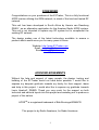
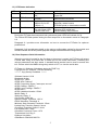
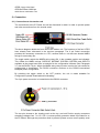
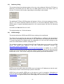
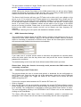
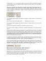
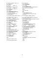
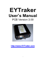
EYTraker
User’s Manual
PCB Version 3.00
http://www.EYTraker.com
1
FOREWORD
Congratulations on your purchase of the EYTraker, This is a fully functional
APRS tracker utilizing the GSM network, in stead of the tried and tested RF
network.
This unit has been developed in South Africa by Hennie van Rensburg
ZS6EY, as an alternative application for the Amateur Radio APRS system.
This unit is not intended to replace any RF system but to compliment the
existing RF network.
The design makes use of the latest technology available to ensure a
product which would serve you for many years to come.
Website: http://www.EYTraker.com
Email: [email protected]
Email: [email protected]
ACKNOWLEDGEMENTS
Without the help and support of many people, the design, testing and
building of the EYTraker would not have been possible. I would like to
express my deepest gratitude towards my family for their support, ideas
and help in this project. I would also like to express my gratitude towards
Louis Haarhoff, ZS6BD. Thank you very much for the support on both
technical and editorial inputs into this project and assisting me to produce a
project of this nature.
APRSTM is a registered trademark of Bob Bruninga WB4APR.
This project is by Radio Amateurs, for Radio Amateurs.
2
TABLE OF CONTENTS
SECTION 1
SECTION 2
`
INTRODUCTION
4
1.1
Overview
1.2
APRS Packet detail
1.3
LED Status indication
1.4
Boot sequence Serial information
CONNECTION
6
2.1 Connections to the tracker unit
2.2 Connecting to the GSM and GPS Network
SECTION 3
CONFIGURATION SOFTWARE
9
3.1 APRS Station
3.2 Mobile Delay
3.3 Stationary Delay
3.4 GPRS Settings
3.5 GPRS Connection Settings
3.6 Connecting to the EYTraker Unit
3.7 Advanced Settings
3.8 Additional Information
3.9 Future Developments
SECTION 4
SUPPORT DATA
4.1 uBlox GPS Module Specifications
4.2 Telit GM862-XXXX Module Specifications
4.3 EYTraker Specifications
4.4 APRS Icon tables
14
GLOSSARY OF TERMS
3
1) Introduction
1.1) Overview
The EYTraker unit was designed as part of a new generation of APRS tracking devices that
will add to the growing number of units that currently support live and realtime APRS
tracking. The unit is different from the current tracking units available from various sources,
based on the fact that the tracking unit does not use conventional HAM frequency RF
technology, but rather utilises the GSM band, in particular the GPRS functionality, of the
GSM system to relay APRS packets.
The EYTraker unit incorporates a complete realtime APRS tracking solution by providing the
user with an onboard GPS device, a Quad band OEM GSM module with SIM card holder
and an integrated micro-controlled management system to control the OEM modules.
1.2) APRS Packet details
The EYTraker unit connects directly to an APRS server anywhere in the world and will relay
APRS compatible packages to the APRS server to be distributed across the worldwide
APRS network. The unit also includes various additional payloads, with the APRS standard
packet, to add value to the APRS standard packet.
Standard APRS Packet Payload:
ZS6EY-9>APGPRS,TCPIP*:/281013z2649.21S/02750.28E>010/032/
ZS6EY-9
APGPRS
TCPIP
281013z
2649.21S
02750.28E
>
010
032
This is the APRS Station Callsign – SSID
This is the unique EYTraker APRS Identification Code
This indicates the packet originated from the internet
The first 2 digits are the date and four digits with Zulu time from the GPS
Latitude Data
Longitude Data
APRS Icon (car) See Paragraph 4.4 for more detail
Course over Ground in degrees
Speed over Ground in knots
Additional EYTraker APRS payload:
A=004952 43C 5St 0020.7km If 12.45V
A=004952
43C
5St
0020.7km
If
12.45V
Altitude encoder with altitude data in feet
Module internal temperature (Deg F is also available)
Current vehicle movement status
Integrated Odometer
Current Vehicle Ignition status
Current Vehicle battery voltage
The EYTraker unit requires only a 7 – 15 V DC supply, GSM antenna and GPS antenna to
perform the tracking function.
In addition there is a DB9 serial port which can be used for future software upgrades via
bootloader. It can also be utilised for the acquisition of the GPS NMEA string or the
configuration of the module via the provided software. A small switch toggles the module
into configuration/bootload mode or NMEA string relay mode.
.
4
1.3) LED Status Indication
LED
Red
Function
Power Status
Blue
GSM Status
Green
Beacon Status
Yellow
Error Status
Flash Pattern
On Off 1s flash 3s flash 1s On/1s Off –
200ms On/1s Off100ms x 3
1s flash x 20
On with Green LED100ms Flash x oo
Indication
Power On
Power Off
GSM service connecting
GSM context connected
Moving status beacon
Stationary status beacon
EPROM upload or download successful
Module connecting
Indicates GPS signal bad
Indicate battery low protection
During the EYTraker boot sequence both yellow and green LEDS will indicate for 2s.
The Yellow LED flash pattern during the boot sequence is discussed in detail in Paragraph
2.2.
Paragraph 2.1 provides more information on how to connect the EYTraker for optimum
performance.
Paragraph 3 will provide more detail on the various configuration options for the module and
will also indicate the APRS packet payload changes with the different configurations.
1.4) Boot Sequence Serial Information
When the module is booted for the first time or the power is cycled, the EYTraker will output
a serial data string at a baud rate of 9600 bps via the serial connection, indicating the
various parameters and their status. A standard serial terminal can be used to access this
info. Please switch the NMEA string relay switch to OFF, to view the serial data.
EYTraker (c) Software & Hardware design by ZS6EY (c)
Copyright on PIC software - HR van Rensburg
******** Copy Strictly Prohibited *******
Software Version V3.26
Bootloader Active
APRS Port: 14580
GPRS APN: "internet"
APRS Connection Server: "www.aprs-za.com"
APRS CallSign: ZS6EY-7
APRS Logon CallSign: ZS6EY-7
APRS Icon: v
APRS Validation Number: 15344
Mobile Delay: 2
Stationary Delay: 2
Odo Preset: 00000 km
Ignition Voltage Threshold: 1320 V
HDOP Odometer Threshold: 6
Minimum Sats Odometer Threshold: 3 Sats
Limited Sats Transition Speed: 6 knots
Good Sats Transition Speed: 2 knots
Low Speed Sats: 5 Sats
Odometer Correction Factor: 1070
Temperature Unit: Deg C
Distance Unit: Miles
GSM Band: GSM 900/1800 ZA
5
GPRS Logon: Not Used
GPS Baud Rate: 9600 bps
APRS Server Verification: ON
2) Connection
2.1) Connections to the tracker unit
The connections to the EYTraker unit will be discussed in detail: In order to provide power
and other connections from the outside world.
The above diagram details the front view of the tracker unit. The functions of the four LED’S
have already been discussed in the previous paragraph. The 9 pin Serial connection
provides the necessary connection to a PC, external radio or unit that can decode NMEA
strings for secondary use.
The toggle switch selects the NMEA string relay ON, in the upwards position as indicated.
This makes the NMEA strings: $GPGGA, $GPRMC, $GPGSA, $GPZDA and $GPVTG
available at the preset baud rate, as selected in the configuration software (See Paragraph
3.7) via the RS232 TX pin. When the NMEA string relay function is active the unit cannot be
programmed or bootloaded. The RS232 connector conforms to the RS232 international
accepted pinout configuration.
By switching the toggle switch to the OFF position, the unit is made available for
Configuration upload, download and bootloading.
The 3-pin power connector is located below the RS232 connector.
The two pins closest to the locating notch at the top, are both Positive supply connectors
accepting voltages from 7 to 15 V DC. A reverse polarity protection diode is provided for on
the PC Board. Although the protection diode is present, please ensure correct polarity at all
6
times to protect the sensitive circuitry. The single pin, located at the bottom, functions as the
Ground or Negative supply pin.
Replacement bulkhead male sockets and female plugs can be obtained from RS
Components with Part numbers: Bulkhead male sockets:
464-426
Female Plugs
464-397
The back view of the EYTraker unit contains the RF connections.
The SMA female bulkhead connections are provided as indicated. Closest to the heatsink is
the GSM or Cell phone antenna. (SMA connector). This connector will accept any dual band
GSM antenna terminated in a male SMA connector. In order for the unit to function on both
the 900 MHz and 1800 MHz GSM bands, the use of a dual band antenna is recommended.
Both the “rubberduck” or window mount GSM antennas have been tested with the unit.
Please unsure that the GSM antenna is compatible with the specific GSM signal provider
frequencies.
The GPS SMA Female bulkhead connector requires an active GPS antenna with a supply
voltage of 3V. The unit will not function with a passive GPS antenna. The location of the
antenna should be with a reasonable clear view of the sky, to provide the necessary GPS
coverage for accurate navigation.
The onboard GPS engine has proven to be very sensitive in urban canyons and limited
coverage areas, but the user must try to ensure a reasonable clear view of the sky.
All units are provided with either a uBlox RCB-LJ 16 channel GPS engine or a Telit
GPS/GSM combo unit. Please refer to the specification section of this document for more
information on the installed OEM units.
7
2.2) Connecting to the GSM and GPS Network
The EYTraker software was tested extensively under various conditions and on different
GSM mobile providers, to ensure the most stable connection, via GPRS, to the APRS
server. Both MTN and Vodacom SIM cards have been tested with the EYTraker unit.
Ensure that the SIM card is inserted into the GSM module. This can be done by carefully
unscrewing the back plate (where the heatsink and SMA bulkhead connectors are located)
and inserting the SIM card into the Telit module. The SIM card will click into place. Please
follow the indicated direction as indicated on the Telit Module.
Ensure that the SIM card conforms to the following:
• This tracker unit does not provide PIN request authentication. Please disable the PIN
request on the SIM card by means of a mobile phone, before inserting the SIM into the
tracker unit.
• Ensure that the SIM card has sufficient air time loaded.
• Ensure that the GPRS (or Data) function on the SIM card is activated. Your mobile
service provider can help you to determine the status and/or activating the GPRS
service.
A typical connection sequence will have the following tell-tale LED indications:
• When power is applied to the unit, the Red LED will light solid and the Yellow and Green
LED’s will light for 2 seconds during microprocessor boot sequence.
•
The Yellow LED will flash 20 times, every second, while the Blue LED will flash once
every second to indicate GSM network acquisition. The Blue LED should start to flash
once every 3 seconds in this period. If the Blue LED does not progress to the 3 second
flash pattern, this will indicate a GSM module connection problem: No antenna, wrong
antenna, no SIM card, no airtime loaded, unregistered SIM card, SIM card PIN request
is activated.
Allow the unit to make a few attempts before resetting the device and checking the
suggested causes.
•
Once the Blue LED is flashing every 3 seconds the GSM network is attached. The
Yellow LED will stop flashing and go steady Yellow to indicate GPRS Context activation.
If the Yellow LED goes into a 1 second flash pattern and the Blue LED back to 1 second
flash pattern the GPRS context could not be initiated. Possible causes: No airtime,
GPRS not activated on SIM card, GPRS Network not available or busy. Successful
GPRS context activation will be indicated by the Yellow LED switching off.
Allow the unit to make a few attempts before resetting the device and checking the
suggested causes.
•
During the Yellow LED’s off period, the unit is attaching to the APRS server. If the Yellow
LED goes into a 1 second flash pattern and the Blue LED back to 1 second flash pattern
the APRS server could not be successfully connected. Possible causes: Wrong APRS
server URL, wrong APRS server port, wrong validation code with Server Verify set to the
ON position.
Allow the unit to make a few attempts before resetting the device and checking the
suggested causes.
8
•
The Yellow LED lighting up again indicates successful APRS server logon. The Yellow
LED will now stay on until the GPS has achieved navigation status. When navigation
status is achieved the yellow LED will go off and the green LED will flash 1 second on / 1
second off to indicate mobile beacon status.
•
If the vehicle does not move for more than 1 minute the green LED will flash 200ms / 1
second off to indicate stationary status.
•
A flashing Green LED and a solid Yellow LED indicates Poor GPS signal and will results
in a special GPS INVLD APRS Packet being logged by the tracker unit.
Please Note: The GPRS networks of all four GSM network providers are very reliable but
please keep in mind that the EYTraker is dependent on the GPRS network to be functional
to relay APRS tracking packets. The EYTraker will not relay APRS packets when the GPRS
network is down.
3) Configuration Software
The EYTraker provides a comprehensive Windows based configuration interface to
personalise the unit for specific networks and requirements.
3.1) APRS Station
This window allows the APRS Call sign and SSID to be configured. The software only allows
9 digits to be entered for a call sign, including the ‘-‘ sign eg. ZS6EY-7
The Icon is set as per the APRS convention. Only one letter is supported in the software. All
APRS icons are supported. The EYTraker unit currently only supports the Primary APRS
Icon table.
3.2) Mobile Delay
This window allows the mobile delay of the unit to be configured. While the EYTraker is
moving, as sensed from the GPS unit, an APRS packet can be sent either every 30s, 1
minute or 2 minutes, depending on the setting in this window.
The additional EYTraker APRS payload will indicate 0Mv for a 30 second beacon, 1Mv for a
1 minute beacon and 2Mv for a 2 minute moving beacon in the APRS packet. A typical
extended payload for a 2 minute beacon will have the following structure:
A=004952 43C 2Mv 0020.7km In 14.45V
The default setting is a 1 minute beacon.
9
3.3)
Stationary Delay
This window allows the stationary delay of the unit to be configured. While the EYTraker is
stationary, as sensed from the GPS unit, an APRS packet can be sent either every 10
minutes, 15 minute or 20 minutes, depending on the setting in this window.
The additional EYTraker APRS payload will indicate 1St for a 10 minute stationary beacon,
5St for a 15 minute stationary beacon and 2St for a 20 minute stationary beacon in the
APRS packet. A typical extended payload for a 20 minute beacon will have the following
structure:
A=004952 40C 2St 0020.7km If 12.45V
The default setting is a 15 minute beacon.
3.4)
GPRS Settings
This window allows the GPRS and APRS Server settings to be configured.
The logon call sign could be the same as the APRS callsign or a different call sign could be
used. This is the callsign that will be seen on the APRS server as relaying the APRS data.
To reduce the amount of callsigns used, the suggestion is to use the same callsign as was
used in the APRS Station window. (Paragraph 2.1)
The validation number is a unique UIView32 5 digit ID that allows you to verify to an APRS
server. You should have obtained it with your UIView32 registration. (Please visit
or
http://www.eytraker.com/Links.htm
http://www.apritch.myby.co.uk/uiv32_uiview32.php?lang=english to register for a UIView
validation number) If this number is not correct or omitted the server will verify but your
packets will not be relayed via RF. Packets are then limited to the internet network and will
not be seen on RF. The TCPXX* string in the APRS packet payload will indicate this.
APRS server is the URL where the APRS server is located. An IP address can also be used.
Please Note: Do NOT include the http:// portion of the URL.
APRS Port is the specific APRS port on the server to use for connection. Information on
ports can be found at the APRS server status page, usually in port 14501. http://www.aprsza.com:14501 is a typical APRS server status page with connection port details available.
10
The port number is limited to 5 digits. Please refer to the EYTraker website for more APRS
servers. http://www.eytraker.com/Links.htm
GPRS APN is the Access Point Name of the GSM network that you will be using. Please
confirm the APN with your mobile network provider. Also ensure that your SIM card is GPRS
enabled, otherwise the GSM module will not be able to connect.
The Server Verify function will force your EYTraker unit to either verify your callsign on the
server or not. If it is critical for the EYTraker packet to be transmitted via an IGate onto RF
then set the option to Yes and ensure the Validation number is correct. If this function is set
to Yes and the validation number is not correct the EYTraker unit will NOT connect to the
server. If you don’t have a Validation number set this option to No to logon to the APRS
server but remain Unverified. Please bear in mind that an unverified APRS station will be
limited to the APRS internet network and will not be IGated onto Ham frequency RF
networks.
Please note: Selecting No in this option will disable the Validation window.
3.5)
GPRS Connection Settings
This configuration window allows the GPRS network username and password to be set, as
required by some GSM networks. None of the South African mobile network providers
require a username or password for GPRS to work. When the Not Used option is selected
the username and Password text boxes are not available.
If you make use of a mobile service where a username and password is required please
select the Active option from the drop down menu and provide the correct username and
password for connection.
The default setting is Not Used with South African based GSM network providers.
Please Note: Using this function incorrectly could prevents the GSM module from
connecting to Internet.
3.6)
Connecting to the EYTraker Unit
This window allows the user to connect and upload, or download, the set configuration to
the EYTraker unit. Once the user has set all the parameters, select the correct COM port
connected to the tracker unit. Toggle the switch on the Tracker Unit to switch the GPS
NMEA string relay OFF.
•
•
Connect the comport cables between the PC and the EYTraker unit.
Click on Connect.
Once the EYTraker unit has successfully connected, the current EYTraker software version
will be displayed in the yellow text box and the Write and Read buttons will become active
for 5 seconds. The configuration is uploaded by clicking the Write button while it is active.
The unit configuration residing in the EEPROM of the EYTraker unit can be obtained by
clicking on the Read Button.
The Green LED will flash three times if the configuration upload or download was
successful. The EYTraker unit will now reboot automatically with the new configuration.
11
See the Website for the Latest Firmware version. http://www.eytraker.com/Down.htm
If garbage letters appear in the Software Version window when Connect button is clicked;
either the Com Port is incorrectly selected or the NMEA String relay switch is still on. Select
the correct COM port or switch off the NMEA string relay and restart the program.
Please Note: The EEPROM on the EYTraker can only be programmed with the Windows
software during certain sequence:
• During the first 20 seconds of the initial boot sequence.
• During the Moving Beacon sequence.
• During the Stationary Beacon sequence.
The upload function is NOT available during GPRS logon, APRS logon and GPS navigation
waiting period.
3.7)
Advanced Settings
This configuration window allows the user to change the advanced settings of the EYTraker
unit. Great care must be taken when these settings are changed to ensure that the unit
functions correctly.
Odometer Function
Most of the settings in this window relates to the Odometer function of the EYTraker. The
EYTraker has been equipped with a complex odometer algorithm that will measure distance
travelled, with GPS coverage, to an accuracy of 5% error within 100 meter. Errors of
between 1% and 2% of distance travelled are more common.
Odometer Preset allows the user to preset the odometer of the EYTraker. The distance
calculations will start from the preset distance. The format is 5 digits with the last digit being
in 100’s of Meters. For example, a preset distance of 330.4 km will be entered as 03304 in
the text box provided.
The Ignition threshold function plays a very important role in the Odometer calculations and
functions with the Ignition Sense option. With the Ignition Sense set to Off, the ignition
threshold is preset to 1.00 V and the window is locked. The Odometer will now calculate
distance continuously based on a good or bad GPS signal. The drawback to this function is
that the vehicle could appear to clock up distance even if the vehicle is stationary, due to
bad GPS signal quality. This setting is only used when the EYTraker is powered from a
battery where no Battery voltage fluctuations can be recorded.
The extended APRS payload will indicate as follows for Ignition Sense Off:
A=004952 43C 2Mv 0020.7km I- 14.45V
When Ignition sense is switched On, the Ignition threshold is used to determine if the
Odometer must calculate distance or not. The EYTraker unit will measure the current battery
voltage and if the battery voltage is above the Threshold voltage for example 14.45V is
above 13.20V, odometer calculations will be done i.e. it is assumed by the unit that the
12
vehicle ignition is on. If the battery voltage is below the Ignition Threshold for example
12.22V is below 13.20V it is assumed by the unit that the vehicle’s ignition is off and that the
vehicle is stationary.
This function provides the most accurate odometer functionality and is recommended. To
calibrate the ignition sense: measure the vehicle battery voltage with ignition off. Now
measure the battery voltage with the engine running using a multi-meter. Take the average
of the two voltages as the Ignition Voltage Threshold. 13.20V is entered as 1320 in the
textbox provided.
The extended APRS payload will indicate as follows for Ignition Sense On with Vehicle
Ignition On:
A=004952 43C 2Mv 0020.7km In 14.45V
Odometer function active
The extended APRS payload will indicate as follows for Ignition Sense On with Vehicle
Ignition Off:
A=004952 43C 2Mv 0020.7km If 12.45V Odometer function not active
The Vehicle battery voltage is continuously displayed independent of the Ignition sense
setting.
The Auto button makes parameter suggestions for Ignition Sense On and Off. The settings
for Ignition Sense Off is much tighter than for Ignition Sense On due to the nature of the
GPS signal to provide inaccurate odometer data when Ignition Sense is Off. Please use the
suggested parameters with the associated Ignition Sense setting. The individual parameters
can be altered when the extent of the change is understood. Too low parameter settings will
make the odometer function inaccurate.
To complement the Ignition Sense function the Odometer will check 4 parameters before
performing an odometer calculation. This will prevent the odometer algorithm from recording
inaccurate measurements. The user can set 3 of these 4 parameters.
HDOP Threshold setting is the Horizontal Dilution of Precision GPS factor that will determine
the accuracy of the GPS data. The higher the HDOP Threshold value the more likely the
odometer errors will become. The HDOP Threshold is set lower for Ignition Sense Off
scenario’s to guard against odometer errors due to poor GPS signal quality.
Ignition Sense On: Auto Predict Button: HDOP Threshold = 6
Ignition Sense Off: Auto Predict Button: HDOP Threshold = 3
HDOP Threshold is user selectable with a range of 1 – 7.
Minimum Sats in View provides the user with a second parameter to make the odometer
calculations more tight and less error prone when not using Ignition Sense in the On
position. When the GPS reports less satellites than the user specified amount of satellites
the odometer calculations will not be performed.
13
The value is set higher when Ignition sense is used in the Off position to limit Odometer
errors.
Ignition Sense On: Auto Predict Button: Minimum Sats in View = 3
Ignition Sense Off: Auto Predict Button: Minimum Sats in View = 4
Minimum Sats in View is user selectable with a range of 2 – 6.
Ignition Sense provides the third parameter to control odometer accuracy, as already
discussed. The odometer will be most accurate in the On position with the correct Threshold
Voltage set.
The fourth parameter that governs odometer accuracy is not user set but determines if the
GPS is navigating in 2D or 3D mode. Odometer calculations are only performed when the
GPS navigates in 3D mode.
The Odometer calculations accuracy can be alerted by a correction factor. This factor is set
at 107.0 and entered into the textbox as 1070. This factor will affect the odometer accuracy
and should only be changed in small increments if the odometer is found to be reading too
high or too low.
To reduce the odometer reading reduce factor to, for example, 106.8 and do distance tests.
To increase the odometer reading increase factor to, for example, 107.2 and do distance
tests.
Please use this setting with care to avoid odometer inaccuracy.
The EYTraker unit can measure distance in both kilometres or miles depending on user
preference.
Selecting the required distance unit will reflect on the Odometer preset window and in the
extended APRS packet payload:
A=004952 43C 2Mv 0020.7km If 12.45V for kilometres
A=004952 43C 2Mv 0020.7mi If 12.45V for miles
Please Note: The Odometer algorithm will calculate distance as long as there is a GPS
signal strong enough to obtain 3D navigation. Even during GSM re-attach sequences and
GPRS network outages, the odometer remains active.
Other Advanced Functions:
The transition speed from stationary APRS beacon to moving beacon is governed by three
parameters:
The Low Speed Threshold parameter determine how many satellites must be visible for the
GPS module to determine at what speed the EYTraker unit will make the transition from
stationary to moving. These three parameters prevent poor GPS signal or coverage to
cause incorrect movement data to be transmitted.
14
With the current settings as an example: The EYTraker will only transition to moving status
at 2 knots if more than 6 satellites are visible to the GPS module and only transition at 6
knots if less than 6 satellites are visible to the GPS module.
With Ignition Sense Off the values become tighter. Please use the Auto Suggestion button
for suggested values for Ignition Sense On and Off.
Ignition Sense On: Auto Predict Button: Limited Sats Speed = 6
Ignition Sense Off: Auto Predict Button: Limited Sats Speed = 12
Limited Sats Speed is user selectable with a range of 4 – 14.
Ignition Sense On: Auto Predict Button: Good Sats Speed = 2
Ignition Sense Off: Auto Predict Button: Good Sats Speed = 3
Good Sats Speed is user selectable with a range of 1 – 9.
Ignition Sense On: Auto Predict Button: Low Speed Threshold = 6
Ignition Sense Off: Auto Predict Button: Low Speed Threshold = 8
Low Speed Threshold is user selectable with a range of 4 – 9.
Too low settings will results in false movement beacons being generated.
The module temperature can be viewed in Degrees Celsius or Degrees Fahrenheit.
A=004952 43C 2Mv 0020.7km If 12.45V for Degrees Celsius
A=004952 66F 2Mv 0020.7mi If 12.45V for Degrees Fahrenheit
The EYTraker unit can accommodate both 4800 bps and 9600 bps GPS signals. The unit
was designed to accept either the u-Blox RCB-LJ GPS module or the Telit GM862-GPS
module at both baud rates.
Please select the correct GPS NMEA Baud rate for the unit installed.
The GSM Band can be selected from the dropdown menu. South Africa uses BAND 0 and
the USA will use BAND 3. This information can be obtained from the mobile service
providers.
BAND 0 is default for South Africa.
15
3.8)
•
•
•
•
•
•
3.9)
•
•
•
•
Additional information
The unit has a special APRS Packet to indicate that the GPS signal is too weak to
navigate with. The APRS Extended Packet will indicate GPS INVLD if the GPS signal
quality is poor. The beacon time will extend to 30 minutes by default. Once the GPS
signal is restored again, the unit will continue to function as normal.
The unit features a low voltage protection at 6.5 volts to ensure that the GSM module
can safely shutdown without corrupting the GSM Module EEPROM data. A fast flashing
yellow LED will indicate this condition. The unit will have to be reset to exit this state.
The NMEA duplication on the Serial Port can be used to connect a Kenwood TM D-700
or a NMEA packet monitoring software with the NMEA duplicating switch on.
The EYTraker unit supports both uBlox RCB LJ firmware version 3 and version 5.
The transition from moving beacon to stationary beacon is automatic and takes place
when the unit has been stationary for 2 minutes with the GPS reporting 0 knots for these
2 minutes.
The unit will stay connected to the GPRS network if the SIM card has credit and the
GPRS network is working. The unit was designed to be autonomous and all effort has
been made to reduce any user interaction to a minimum.
Future Developments
The Windows configuration software will include the Bootloader function.
The Telit GM862-GPS can be used as a combination GSM/GPS module. The EYTraker
firmware supports both modules in the firmware. PCB already supports the function
The third A to D can be implemented. PCB already supports the function.
Vehicle moving alert via SMS.
16
4) Support Data
4.1) uBlox RCB-LJ GPS Module Specifications
•
•
•
•
•
•
•
•
•
•
•
•
•
•
•
•
•
•
•
High sensitivity
o
-150 dBm tracking
o
-140 dBm acquisition
Ultra-low power consumption
o
175 mW with 3.3 V supply voltage
Fast Time-To-First-Fix (TTFF)
o
34 s cold start
o
<3.5 s hot start
Excellent navigation performance
o
2.5 m CEP
o
2.0 m CEP with DGPS / SBAS (depending on accuracy of correction
data)
o
No accuracy compromises at low signal levels
o
Active multipath detection and removal
Industry-standard form factor for easy plug-in integration
Maximum flexibility
o
Extensively configurable
Active antenna support
Active antenna supervision for short and open circuit detection
16 channel GPS receiver
8192 simultaneous time-frequency search bins
4Hz position update rate
ANTARIS Positioning Engine
o
ATR0600 RF front-end IC
o
ATR0620 Baseband IC with integrated ARM7TDMI
FLASH memory
DGPS and SBAS (WAAS, EGNOS) support
FixNOW™ power saving mode
Operating Voltage 2.7 to 3.3 V
Battery supply pin for internal backup memory and real time clock
Industrial operating temperature range -40 to 85°C
Small size: 71 x 41 x 11 mm
Please refer to the Datasheet Download section of the EYTraker website for more
information. http://www.eytraker.com/docs.htm
The EYTraker unit supports both uBlox Firmware Version V3.00 and V5.00.
17
4.2) Telit GM863-QUAD GSM Module Specifications
Dimensions: 44 x 44 x 6,7 mm
Weight: 23 g
•
•
•
•
•
•
•
•
•
Pin to Pin backward compatible
GSM Quad Band
RoHS Compliant
On Board SIM Holder
GPRS Class 10
Embedded TCP/IP Stack
Embedded FTP and SMTP Client
Extended Temperature Range
Extended RF Sensitivity
Please refer to the Datasheet Download section of the EYTraker website for more
information. http://www.eytraker.com/docs.htm
The EYTraker supports the GM862-GPRS, GM862-QUAD and GM862-GPS modules.
4.3)
EYTraker Specifications:
•
•
•
•
•
•
•
•
•
•
•
•
APRS compatible string to UIView and AGW Tracker. Unique identifier: APGPRS
UIView Java Server login and server authentication
Altitude encoding
Module operating Temperature
Moving and Stationary Beacon Status
1 minute beacons while moving and 15 min beacons when stationary as default.
Auto GSM network search and high speed GPRS auto re-attach when the TCPIP
socket is lost.
Works both MTN and Vodacom networks. You supply the SIM card. About R30
per month for GPRS data. 15MB of GPRS data, out of bundle.
NMEA data out feed on COM port at 9600/4800 baud to attach to Kenwood TMD700 or PC software.
External Active GPS antenna and GSM antenna.
Standard 12V vehicle power required. Draws about 130 mA while operational.
Four status LED's: GSM Status, Beacon Status, GPS Status, Power
Bootloader included on PIC for firmware updates
Odometer function
Full Windows configuration program for changing information like Callsigns,
durations etc.
18
4.4) APRS Primary Symbol List (Courtsey of Bob Bruninga’s Website)
If you require more info on the APRS Symbol tables please visit the EYTraker website:
http://www.eytraker.com/Links.htm or http://eng.usna.navy.mil/~bruninga/aprs/symbolsX.txt
Please Note: EYTraker only supports the left hand column: Basic/Primary Symbol Table
/$ XYZ BASIC SYMBOL TABLE
-- --- ------------------------- -/! BB Police, Sheriff
/" BC reserved (had been rain)
/# BD DIGI (white center)
/$ BE PHONE
/% BF DX CLUSTER
/& BG HF GATEway
/' BH Small AIRCRAFT (SSID = 7)
/( BI Mobile Satellite Station
/) BJ Wheelchair (handicapped)
/* BK SnowMobile
/+ BL Red Cross
/, BM Boy Scouts
/- BN House QTH (VHF)
/. BO X
// BP Dot
\$ XYZ OTHER SYMBOL TABLE (\)
--- ---------------------\! OB EMERGENCY (!)
\" OC reserved
\# OD# NUMBERED STAR (green)
\$ OE Bank or ATM (green box)
\% OF
\& OG# GATEway I=2way, R=1way
\' OH Crash site
\( OI CLOUDY
\) OJ Firenet MEO, MODIS Earth Obs...(NEW)
\* OK SNOW
\+ OL Church
\, OM Girl Scouts
\- ON House (HF)
\. OO Ambiguous Plot (Big Question mark)
\/ OP Waypoint Destination (D7/D700)
/$ XYZ PRIMARY SYMBOL TABLE
-- --- ------------------------- -/0 P0 # circle (obsolete)
/1 P1 TBD (these were all)
/2 P2 TBD (numbered circles)
/3 P3 TBD (looking like billiard)
/4 P4 TBD (balls until we came)
/5 P5 TBD (up with Overlays)
/6 P6 TBD (Now they are all)
/7 P7 TBD (available for new)
/8 P8 TBD (definitions...)
/9 P9 TBD
/: MR FIRE
/; MS Campground (Portable ops!)
/< MT Motorcycle (SSID = 10)
/= MU RAILROAD ENGINE
/> MV CAR
(SSID = 9)
/? MW SERVER for Files
/@ MX HC FUTURE predict (dot)
/A PA Aid Station
/B PB BBS or PBBS
/C PC Canoe
/D PD
/E PE EYEBALL (Eye catcher!)
/F PF Farm Vehicle (tractor) NEW
/G PG Grid Square (6 digit)
/H PH HOTEL (blue bed symbol)
/I PI TcpIp on air network stn
/J PJ
/K PK School
/L PL Logged-on PCuser (Jan 03)
/M PM MacAPRS
/N PN NTS Station
/O PO BALLOON
(SSID = 11)
/P PP Police
/Q PQ TBD
\$ XYZ ALTERNATE SYMBOL TABLE (\)
--- -------------------------\0 A0# Overlayed CIRCLE (E/I =IRLP/Echolink)
\1 A1
\2 A2
\3 A3
\4 A4
\5 A5
\6 A6
\7 A7
\8 A8
\9 A9 Gas Station (blue pump)
\: NR Hail
\; NS Park/Picnic area
\< NT ADVISORY
\= NU
\> NV# NUMBERED CAR
\? NW INFO Kiosk (Blue box with ?)
\@ NX HURICANE/Trop-Storm
\A AA# NUMBERED BOX
\B AB Blowing Snow
\C AC Coast Guard
\D AD Drizzle
\E AE Smoke
\F AF Freezing rain
\G AG Snow Shower
\H AH Haze
\I AI Rain Shower
\J AJ Lightening
\K AK Kenwood HT (W)
\L AL Lighthouse
\M AM
\N AN Navigation Buoy
\O AO Rocket (new June 2004)
\P AP Parking
\Q AQ QUAKE
19
/R PR REC. VEHICLE (SSID = 13)
/S PS SHUTTLE
/T PT SSTV
/U PU BUS
(SSID = 2)
/V PV ATV
/W PW National WX Service Site
/X PX HELO
(SSID = 6)
/Y PY YACHT (sail) (SSID = 5)
/Z PZ WinAPRS
/[ HS Jogger
/\ HT TRIANGLE(DF station)
/] HU MAIL/PostOffice (was PBBS)
/^ HV LARGE AIRCRAFT
/_ HW WEATHER Station (blue)
/` HX Dish Antenna
/$ XYZ LOWER CASE SYMBOL TABLE
-- --- ------------------------- -/a LA AMBULANCE (SSID = 1)
/b LB BIKE
(SSID = 4)
/c LC Incident Command Post (NEW)
/d LD Dual Garage (Fire dept)
/e LE HORSE (equestrian)
/f LF FIRE TRUCK (SSID = 3)
/g LG Glider
/h LH HOSPITAL
/i LI IOTA (islands on the air)
/j LJ JEEP
(SSID-12)
/k LK TRUCK
(SSID = 14)
/l LL Logged-on laptop (Jan 03)
/m LM Mic-E Repeater
/n LN Node
/o LO EOC
/p LP ROVER (puppy, or dog)
/q LQ GRID SQ shown above 128 m
/r LR ANTENNA like Radio station
/s LS SHIP (pwr boat) (SSID-8)
/t LT TRUCK STOP
/u LU TRUCK (18 wheeler)
/v LV VAN
(SSID = 15)
/w LW WATER station
/x LX xAPRS (Unix)
/y LY YAGI @ QTH
/z LZ
/{ J1
/| J2 reserved (Stream Switch)
/} J3
/~ J3 reserved (Stream Switch)
\R AR Restaurant
\S AS Satellite/Pacsat
\T AT Thunderstorm
\U AU SUNNY
\V AV VORTAC Nav Aid
\W AW NUMBERED NWS site (NWS options)
\X AX Pharmacy Rx (Apothicary)
\Y AY
\Z AZ
\[ DS Wall Cloud
\\ DT
\] DU
\^ DV# NUMBERED Aircraft
\_ DW# NUMBERED WX site (green digi)
\` DX Rain
\$ XYZ SECONDARY SYMBOL TABLE (\)
--- -------------------------\a SA ARRL Overlays: ARES(A), WinLINK (W)
\b SB Blowing Dust/Sand
\c SC Civil Defense Overlays R=RACES C=CERTS
\d SD DX spot by callsign
\e SE Sleet
\f SF Funnel Cloud
\g SG Gale Flags
\h SH HAM store
\i SI Indoor BOXn digipeater (w overlay)
\j SJ WorkZone (Steam Shovel)
\k SK SUV
(new 29 June 2004)
\l SL Area Locations (box,circles,etc)
\m SM Value Signpost (3 digit display)
\n SN# NUMBERED TRIANGLE
\o SO small circle
\p SP Partly Cloudy
\q SQ
\r SR Restrooms
\s SS# NUMBERED SHIP/boat (top view)
\t ST Tornado
\u SU# NUMBERED TRUCK
\v SV# NUMBERED Van
\w SW Flooding
\x SX
\y SY Skywarn
\z SZ# Shelter (evacuation) (W Overlay)
\{ Q1 Fog
\| Q2
\} Q3
\~ Q4
20
GLOSSARY OF TERMS
APN
Access Point Name a setting for GPRS
APRS
Automatic Position Reporting System
GPS
The Global Positioning System, usually called GPS, is the only fullyfunctional satellite navigation system
GPRS
General Packet Radio Service (GPRS) is a mobile data service available
to users of GSM mobile phones
GSM
Global System for Mobile Communications
NMEA
The NMEA 0183 protocol is a means by which marine instruments and
also most GPS receivers can communicate with each other. It has been
defined by, and is controlled by, the US based National Marine
Electronics Association.
OEM
Original Equipment Manufacturer
SIM
Subscriber Identity Module, as in smart cards used in cell phones
SSID
A service set identifier (SSID) is a code attached to all packets on a
wireless network to identify each packet as part of that network.
21