1
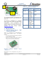
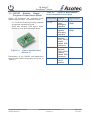
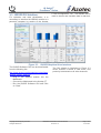
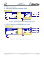
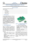
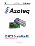
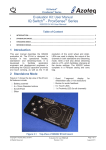
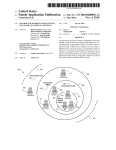
IQ Switch®
ProxSens® Series
IQS253EV02 Evaluation Kit User Manual
IQ Switch® - ProxSense® Series
Table of Contents
IQS253EV02 EVALUATION KIT USER MANUAL ............................................................................................................ 1
TABLE OF CONTENTS .................................................................................................................................................. 1
1
INTRODUCTION............................................................................................................................................. 1
2
EV-KIT MAINBOARD ...................................................................................................................................... 1
3
MODULE BOARDS ......................................................................................................................................... 2
4
REFERENCE DESIGNS ..................................................................................................................................... 5
1 Introduction
This user manual describes the operation of
the IQS253EV02 Evaluation Kit. The EV-Kit is
manufactured in three parts, consisting of a
mainboard, and two separate plug-in module
boards. To adjust IC OTP settings, the main
board can be interfaced to any personal
computer with the Azoteq Configuration Tool
(CT220), and making the adjustments by
means of theUSBProg software. The purpose
of the IQS253EV02 EV-Kit is to help
application and development engineers in
evaluating the IQS253 proximity and touch
sensor.
2 EV-Kit Mainboard
Figure 2.1 illustrates the evaluation kit
mainboard and the two supplied controller
modules. The mainboard supplies power and
other functions to the controller module boards
and is easily operated. Simply plug in the
desired module board into the mainboard and
interface with the IQS253 GUI Software by
means of the Azoteq Configuration Tool
(CT220). Features included in the EV-Kit
mainboard:
Modular design: Connect one of the
supplied IC modules into the mainboard,
or wire into a prototype for rapid
prototyping
Reference designs for IQS253 with user
proximity & touch detection ability
Two separate module boards, one for
projected mode, and one for selfcapacitance mode
Copyright © Azoteq (Pty) Ltd 2012.
All Rights Reserved.
Figure 2.1 IQS253EV02 Mainboard
and controller modules
Usedin Data Streaming Mode:
EV-KIT requires Azoteq Configuration Tool
CTxxx or DS for streaming.
OTP bits can be programmed on the kit
(requires CT220)
Figure 2.2 illustrates the bottom view of the
EV-Kit mainboard.The EV-Kit can optionally be
powered by two 3V coin cell batteries in series,
which are regulated to 3.3V and supplied to the
module board. The EV-Kit mainboard can also
draw power from a USB source by means of
the mini-USB connector provided on the
mainboard (optional).
IQS253EV02 Evaluation Kit User Manual
Revision 1.0
Page 1 of 6
June 2012
IQ Switch®
ProxSense® Series
USB
Power
Port
Table 3.1
IQS253 S-ModeModule
board component description
Component Purpose
C1, C2
Programming
and data
streaming
header
Figure 2.2
Bottom view of EV-Kit
mainboard
The mainboard includes a programming and
data streaming header as also illustrated in the
Figure 2.2.
The EV-Kit is interfaced to a personal
computer for data streaming and programming
OTP options, by means of the Azoteq
Configuration
Tool
(CT220).For
IC
programming and visual data streaming please
utilizethe USBProg and IQS253 GUI software,
provided
on
the
Azoteq
website.
(http://www.azoteq.com).
C3, C4
R4
R1, R2, R3
R5, R6, R7
Power
supply
decoupling
capacitors
Internal
regulator
decoupling
capacitors
Boolean
Output
Sense
electrode
(Cx) series
resistors
(Added ESD
Protection)
Streaming
pull-up
resistors
Typical value
1µF,
100pF
1µF,
100pF
100Ω
470Ω
10kΩ
3 Module Boards
3.1 IQS253 Module Board – Self
Capacitance Mode
Figure 3.1 illustrates the self-capacitance
mode IQS253 Module board. Its features
include:
3 x Touch and proximity sensing channels
in self-capacitance mode
Small and compact PCB layout, which is
easily wired to prototype applications
Figure 3.1 IQS253
marked “S”
Module
board
Descriptions of the components are given in
Table 3.1.
Copyright © Azoteq (Pty) Ltd 2012.
All Rights Reserved.
IQS253EV02 Evaluation Kit User Manual
Revision 1.0
Page 2 of 6
June 2012
IQ Switch®
ProxSense® Series
3.2 IQS253 Module Board –
Projected Capacitance Mode
Table 3.2
IQS253 P-Mode Module
board component description
Figure 3.2 illustrates the projected mode
IQS253 Module board. Its features include:
Component Purpose
3 x Touch and Proximity sensing channels
in projected capacitance mode
Small and compact PCB layout, which
iseasily wired to prototype applications
C1, C2
C3, C4
R4
R1, R2, R3
Figure 3.2
IQS253 module board
marked “P”
Descriptions of the IQS253 self-capacitance
mode module board components are given in
Table 3.2.
Copyright © Azoteq (Pty) Ltd 2012.
All Rights Reserved.
R7, R8, R9
Power
supply
decoupling
capacitors
Internal
regulator
decoupling
capacitors
Sense
electrode
(CTX) series
resistor
(Added ESD
Protection)
Sense
electrode
(CRX) series
resistors
(Added ESD
Protection)
Debug Mode
pull-up
resistors
IQS253EV02 Evaluation Kit User Manual
Revision 1.0
Typical value
1µF,
100pF
1µF,
100pF
470Ω
470Ω
10kΩ
Page 3 of 6
June 2012
IQ Switch®
ProxSense® Series
3.3 IQS253 GUI Interface
For operation and data visualization, it is
necessary to interface the IQS243 module to a
personal computer by means of the Azoteq
Figure 3.3
CT200 Configuration Tool. The IQS243 GUI is
used to stream and visualize data in real-time.
IQS253 Graphical User Interface
The IQS253 Software GUI can be downloaded
from the following link:
http://www.azoteq.com/images/stories/software
/azoteq_iqs253_setup.zip
The GUI display is illustrated in Figure 3.3
where channel 3 shows a valid touch, and
proximity is detected on all other channels.
Plug in the IQS253 module into the
Mainboard
Connect the Mainboard to the Azoteq CT
Run the IQS253 Software GUI and Click
on “Start”.
Copyright © Azoteq (Pty) Ltd 2012.
All Rights Reserved.
IQS253EV02 Evaluation Kit User Manual
Revision 1.0
Page 4 of 6
June 2012
IQ Switch®
ProxSense® Series
4 Reference Designs
4.1 IQS253 Self-Capacitance Reference Design
Connect to sense buttons
(See Appnote: AZD036 for button design
guidelines)
U1
R1
CRX0
2
470
3
R2
CRX1
9
470
VDDHI
CX0/CRX0
VDDHI
CX1/CRX1
VREG
R6
SDA
5
10K
CX2/CRX2
R3
CRX2
VDDHI
4
C4
C3
1uF
100pF
C2
C1
100pF
1uF
R7
SCL
10K
470
7
SDA
VIN
VDDHI
8
SCL
VDDHI
RDY/RF
R4
GND
SDA
6
10
100
SCL
R5
SDA
SCL
SCL
GND
GND
RDY
SDA = Serial Data (I2C)
SCL = Serial Clock (I2C)
RDY = Ready Line
Optional: 100pF capacitors for additional RF immunity.
RDY/ND
B_OUT/CTX
10K
GND
1
IQS253
GND
GND
Figure 4.1
IQS253 Self Capacitance Mode Reference design
4.2 IQS253 Projected Capacitance Reference Design
Connect to sense buttons
(See Appnote: AZD036 for button design
guidelines)
CRX0
U1
R1
2
470
CRX1
CTX0
3
R2
9
470
CRX2
VDDHI
CX0/CRX0
VDDHI
CX1/CRX1
VREG
VDDHI
4
R6
SDA
5
10K
CX2/CRX2
R3
C4
C3
1uF
100pF
C2
C1
100pF
1uF
SCL
10K
470
SDA
SCL
RDY/RF
R4
470
VIN
SDA
R7
7
8
6
10
SCL
R5
SDA
SCL
SCL
GND
GND
10K
RDY
SDA = Serial Data (I2C)
SCL = Serial Clock (I2C)
RDY = Ready Line
Optional: 100pF capacitors for additional RF immunity.
RDY/ND
B_OUT/CTX
GND
1
IQS253
VDDHI
GND
GND
GND
Figure 4.2
Copyright © Azoteq (Pty) Ltd 2012.
All Rights Reserved.
IQS253 Projected Mode Reference design
IQS253EV02 Evaluation Kit User Manual
Revision 1.0
Page 5 of 6
June 2012
IQ Switch®
ProxSense® Series
The following patents relate to the device or usage of the device: US 6,249,089 B1, US 6,621,225
B2, US 6,650,066 B2, US 6,952,084 B2, US 6,984,900 B1, US 7,084,526 B2, US 7,084,531 B2,
US 7,119,459 B2, US 7,265,494 B2, US 7,291,940 B2, US 7,329,970 B2, US 7,336,037 B2, US
7,443,101 B2, US 7,466,040 B2, US 7,498,749 B2, US 7,528,508 B2, US 7,755,219 B2, US
7,772,781, US 7,781,980 B2, US 7,915,765 B2, EP 1 120 018 B1, EP 1 206 168 B1, EP 1 308 913
B1, EP 1 530 178 B1, ZL 99 8 14357.X, AUS 761094
IQ Switch®, ProxSense®, LightSense™, AirButton® and the
trademarks of Azoteq.
logo are
The information in this Datasheet is believed to be accurate at the time of publication. Azoteq
assumes no liability arising from the use of the information or the product. The applications
mentioned herein are used solely for the purpose ofillustration and Azoteq makes no warranty
or representation that such applications will besuitable without further modification, nor
recommends the use of its products for applicationthat may present a risk to human life due to
malfunction or otherwise. Azoteq products are notauthorized for use as critical components in
life support devices or systems. No licenses topatents are granted, implicitly or otherwise,
under any intellectual property rights. Azoteqreserves the right to alter its products without
prior notification. For the most up-to-dateinformation, please refer to www.azoteq.com.
WWW.AZOTEQ.COM
[email protected]
Copyright © Azoteq (Pty) Ltd 2012.
All Rights Reserved.
IQS253EV02 Evaluation Kit User Manual
Revision 1.0
Page 6 of 6
June 2012
Mouser Electronics
Authorized Distributor
Click to View Pricing, Inventory, Delivery & Lifecycle Information:
Azoteq:
IQS253EV02S