1
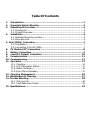
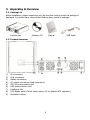
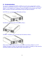
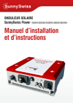
User Manual Hybrid PV Inverter Table Of Contents 1. 2. 3. Introduction ............................................................................................1 Important Safety Warning .....................................................................2 Unpacking & Overview ...........................................................................4 3-1. Pack ing List ........................................................................................ 4 3-2. Product Ov erv iew................................................................................ 4 4. Installation ..............................................................................................5 4-1. Selecting Mounting Location ................................................................ 5 4-2. Mounting Unit..................................................................................... 5 5. Grid (Utility) Connection ...........................................................................7 5-1. Preparation......................................................................................... 7 5-2. Connecting to the AC Utility ................................................................. 7 6. PV Module (DC) Connection ...................................................................8 7. Battery Connection .................................................................................9 8. Load (A C Output) Connection ............................................................. 10 9. Communication .................................................................................... 11 10. Commissioning..................................................................................... 12 11. Operation.............................................................................................. 13 11-1. Interface ........................................................................................ 13 11-2. LCD Information Define................................................................... 13 11-3. Button Definition............................................................................. 15 11-4 Query Menu Operation ..................................................................... 15 12. Charging Manageme nt ........................................................................ 25 13. Maintenance & Cleaning ...................................................................... 27 14. Trouble Shooting .................................................................................. 28 14-1. Warning List ................................................................................... 28 14-2. Fault Reference Codes..................................................................... 29 15. Specifications........................................................................................ 33 1. Introduction This hy brid PV inverter can provide power to connected loads by utilizing PV pow er, utility power and battery power. When PV energy output is good, it w ill pow er connected loads from solar electric (photov oltaic or PV ) pow er, feed power back to grid (utility ), and charge battery. When PV energy output is not suff icient for connected loads, this inverter w ill conv ert the utility at the same time. Hy brid inverter Distribution Box PV module E lectric grids Load Battery Figur e 1 Basic hybr id PV System Overview Depending on different pow er situations, this hybrid inv erter is designed to generate continuous pow er from PV solar modules (solar panels), battery, and the utility. When MPP input v oltage of PV modules is within acceptable range (see specif ication for the details), this inv erter is able to generate power to feed the grid (utility ) and charge battery. This inv erter is only compatible w ith PV module types of single cry stalline and poly cry stalline. Do not connect any PV array types other than these two types of PV modules to the inverter. See Figure 1 for a simple diagram of a typical solar system w ith this hybrid inverter. Note: When PV input v oltage is lower than 250V for 3KW and 150V for 2KW, the power of inv erter w ill de-rate. 1 2. Important Safety Warning Before using the inver ter , please read all instr uctions and cautionary markings on the unit and this manual. Store the manual where it can be accessed easily. This manual is for qualif ied personnel. The tasks described in this manual may be performed by qualif ied personnel only. General PrecautionC onventions used: WA RNING! Warnings identify conditions or practices that could result in personal injury ; CAUTIO N! Caution identify conditions or practices that could result in damaged to the unit or other equipment connected. WA RNING! Before installing and using this inverter, read all instructions and cautionary markings on the inverter and all appropriate sections of this guide. WA RNING! N ormally grounded conductors may be ungrounded and energized when a ground fault is indicated. WA RNING! This inverter is heavy. It should be lifted by at least tw o persons. CAUTIO N! A uthorized serv ice personnel should reduce the risk of electrical shock by disconnecting AC, DC and battery pow er from the inverter before attempting any maintenance or cleaning or w orking on any circuits connected to the inverter. Turning off controls w ill not reduce this risk. Internal capacitors can remain charged for 5 minutes after disconnecting all sources of pow er. CAUTIO N! Do not disassemble this inverter yourself. It contains no user-serv iceable parts. Attempt to serv ice this inverter y ourself may cause a risk of electrical shock or f ire and w ill void the warranty from the manufacturer. CAUTIO N! To avoid a risk of f ire and electric shock, make sure that existing w iring is in good condition and that the wire is not undersized. Do not operate the Inverter w ith damaged or substandard w iring. CAUTIO N! U nder high temperature env ironment, the cover of this inverter could be hot enough to cause skin burns if accidentally touched. E nsure that this inv erter is aw ay from normal traff ic areas. 2 CAUTIO N! U se only recommended accessories from installer . Otherw ise, not-qualif ied tools may cause a risk of f ire, electric shock, or injury to persons. CAUTIO N! To reduce risk of f ire hazard, do not cover or obstruct the cooling fan. CAUTIO N! Do not operate the Inverter if it has received a sharp blow, been dropped, or otherw ise damaged in any way. If the Inverter is damaged, called for an RMA (Return M aterial Authorization). Symbols used in Equipment M arkings Refer to the operating instructions Caution, risk of danger Caution, risk of electric shock Caution, risk of electric shock, E nergy storage timed discharge Caution, hot surface 3 3. Unpacking & Overview 3 -1. Packing List Before installation, please inspect the unit. Be sure that nothing inside the package is damaged. You should have received the follow ing items inside of package: Inverter unit S oftware CD M anual USB cable 3 -2. Product Overview 1) 2) 3) 4) 5) 6) 7) 8) 9) PV connectors G rid connectors Battery connectors AC output connectors (Load connection) RS -232 communication port USB communication port Intelligent slot LCD display panel (P lease check section 10 for detailed LCD operation) Operation buttons 4 4. Installation 4 -1. Selecting M ounting Location Consider the follow ing points before selecting w here to install: Do not mount the inv erter on flammable construction materials. M ount on a solid surface This inverter can make noises during operation which may be perceived as a nuisance in a liv ing area. Install this inverter at eye lev el in order to allow the LCD display to be read at all times. For proper air circulation to dissipate heat, allow a clearance of approx. 20 cm to the side and approx. 50 cm abov e and below the unit. Dusty conditions on the unit may impair the performance of this inv erter. The ambient temperature should be between 0°C and 40°C and relative humidity should be betw een 5% and 85% to ensure optimal operation. The recommended installation position is to be adhered to (v ertical). For proper operation of this inverter, please use appropriate cables for grid connection. The pollution degree of the inverter is PD2. Select an appropriate mounting location. Install the solar inverter in a protected area that is dry, free of excessiv e dust and has adequate air flow. Do NOT operate it w here the temperature and humidity is beyond the specif ic limits. (P lease check the specs for the limitations.) Installation position shall not prevent access to the disconnection means. This inverter is designed with IP 20 for indoor applications only. 4 -2. Mounting Unit WA RNING!! Remember that this inverter is heavy ! P lease be carefully w hen lifting out from the package. Installation to the wall should be implemented w ith the proper screw s. M ount the wall bracket so that the solar inverter can be easily attached to the w all. A fter that, the dev ice should be bolted on securely. The inverter only can be used in a C LOSED E LECTRICAL OPERATING AREA. WA RNING!! FIRE HAZARD. SUITABLE FOR MOUNTING ON CONCRETE OR OTHER NON -COMBUSTIBLE SURFACE ON LY. 5 1. Drill four holes in the marked locations w ith four screw s. 2. 3. Check if the solar inverter is f irmly secured. P lace the unit on the surface and align the mounting holes w ith the four screw s. Note: Recommended specs for screws. 6 5. Grid (Utility) Connection 5 -1. Preparation Before connecting to AC utility, please install a separ ate AC circuit breaker betw een inverter and AC utility. This will ensure the inv erter can be securely disconnected during maintenance and fully protected from ov er current of AC input. NOTE1 : A lthough this inv erter is equipped w ith a fuse (F 6 point on PCB, 250VAC /30A for 3KW; F 6 and F 7 points on PCB, 250VAC /30A for 2KW), it’s still necessary to install a separate circuit breaker for safety consideration. P lease use 250VAC/30A circuit breaker. NOTE2 : The overv oltage category of the AC input is III. It should be connected to the power distribution. WA RNING! It's very important for sy stem safety and eff icient operation to use appropriate cable for grid (utility ) connection. To reduce risk of injury, please use the proper recommended cable size as below. S uggested cable requirement for AC w ire M odel 2KW 3KW N ominal G rid Voltage 101/110/120/127 VAC 208/220/230/240 VAC Conductor cross-section (mm 2) ≥4.17 ≥3.35 AWG no. 10 - 11 10 - 12 5 -2. Connecting to the AC Utility S tep 1: C heck the grid voltage and frequency w ith an AC voltmeter. It should be the same to “VAC” value on the product label. S tep 2: Turn off the circuit breaker. S tep 3: Remove insulation sleeve 8 mm for three conductors. And shorten phase L and neutral conductor N 3 mm. Refer to chart 1. Chart 1 S tep 4: C onnect w ires according to polarities indicated on terminal block. Be sure to connect P E protective conductor ( ) f irst. L→LINE ( brown or black) → Ground (yellow-green) N→ Neutral ( blue) S tep 5: M ake sure the w ires are securely connected. The reference tightening torque is 0.82 N /m. Chart CAUTIO N: To prevent risk of electric shock, ensure the ground w ire is properly earthed before operating this hy brid inverter no matter the grid is connected or not. 7 6. PV Module (DC) Connection CAUTIO N: Before connecting to PV modules, please install separ ately a DC circuit breaker betw een inverter and PV modules. NOTE1 : P lease use 600VDC/25A circuit breaker for 3KW; 500VDC /25A for 2KW. NOTE2 : The overv oltage category of the PV input is II. P lease follow below steps to implement PV module connection: WA RNING: Because this inv erter is non-isolated, only tw o ty pes of PV modules are acceptable: single cry stalline and poly cry stalline w ith only C lass A -rated. To avoid any malfunction, do not connect any PV modules w ith possibility of leakage current to the inv erter. F or example, non-grounded PV modules w ill cause leakage current to the inverter. S tep 1: Check the input voltage of PV array modules. The acceptable input v oltage of the solar inv erter is 250VDC - 450VDC for 3KW and 150VDC-320VDC for 2KW. This sy stem is only applied w ith one string of PV array. P lease make sure that the maximum current load of PV input connector is 13A for 3KW and 15A for 2KW.. CAUTIO N: E xceeding the maximum input v oltage can destroy the unit!! C heck the sy stem before w ire connection. S tep 2: Disconnect the circuit breaker. S tep 3: Remove insulation sleeve 10 mm for positive and negativ e conductors. Refer to chart 3. S tep 4: C heck correct polarity of connection cable from PV modules and PV input connectors. Then, connect positiv e pole (+) of connection cable to positive pole (+) Chart 3 of PV input connector. Connect negative pole (-) of connection cable to negativ e pole (-) of PV input connector. Refer to Chart 4. S tep 5: M ake sure the w ires are securely connected. The reference tightening torque is 1.22 N /m. 8 Chart 4 WA RNING! It's very important for sy stem safety and eff icient operation to use appropriate cable for PV module connection. To reduce risk of injury, please use the proper recommended cable size as below. Conductor cross-section (mm 2) ≥3.35 AWG no. 6 - 12 CAUTIO N: Never directly touch terminals of the inverter. It will cause lethal electric shock. CAUTIO N: Do NOT touch the inverter to avoid electric shock. When PV modules are exposed to sunlight, it may generate DC voltage to the inverter. 7. Battery Connection CAUTIO N: Before connecting to batteries, please install separ ately a DC circuit breaker betw een inverter and batteries. NOTE: P lease only use sealed lead acid battery, vented and G el battery. P lease check maximum charging voltage and current w hen f irst using this inverter. If using Lithium iron or N icd battery , please consult with installer for the details. NOTE: P lease use P lease use 60VDC/100A circuit breaker for 3KW and 60VDC/80A circuit breaker for 2KW. P lease follow below steps to implement battery connection: S tep 1: C heck the nominal voltage of batteries. The nominal input v oltage for hy brid inv erter is 48VDC. S tep 2: U se tw o battery cables. Remove insulation sleeve 12 mm and insert conductor into cable ring terminal. Refer to chart 5. S tep 3: F ollow ing battery polarity guide printed near the battery terminal! P lace the external battery cable ring terminal ov er the battery terminal. Refer to Chart 6. RED cable to the positive terminal ( +) ; BLACK cable to the negative ter minal ( -) . Chart 5 S tep 4: M ake sure the w ires are securely connected. The reference tightening torque is 2.04 N /m. Chart 6 9 WA RNING! It's very important for sy stem safety and eff icient operation to use appropriate cable for battery connection. To reduce risk of injury, please use the proper recommended cable size as below. M odel 2KW 3KW N ominal G rid Voltage 101/110/120/127 VAC 208/220/230/240 VAC Conductor cross-section (mm 2) ≥8.37 ≥13.3 AWG no. ≤8 ≤6 8. Load (AC Output) Connection CAUTIO N: To prevent further supply to the load via the inverter during any mode of operation, an additional disconnection dev ice should be placed on in the building w iring installation. WA RNING! It's very important for sy stem safety and eff icient operation to use appropriate cable for AC connection. To reduce risk of injury, please use the proper recommended cable size as below. M odel 2KW 3KW N ominal G rid Voltage 101/110/120/127 VAC 208/220/230/240 VAC Conductor cross-section (mm 2) ≥4.17 ≥3.35 AWG no. 10 - 11 10 - 12 S tep 1: Remove insulation sleeve 8 mm for three conductors. A nd shorten phase L and neutral conductor N 3 mm. Refer to chart 7. S tep 2: C onnect w ires according to polarities indicated on terminal block. Be sure to connect P E protective conductor ( ) f irst. Refer to Chart 8. Chart 7 L→LINE ( brown or black) → Ground (yellow-green) N→ Neutral ( blue) S tep 3: M ake sure the w ires are securely connected. The reference tightening torque is 0.82 N /m. Chart 8 CAUTIO N: It’s only allowed to connect load to “AC Output Connector”. Do NOT connect the utility to “AC Output Connector”. CAUTION: Be sure to connect L terminal of load to L terminal of “AC Output Connector” and N terminal of load to N terminal of “AC O utput C onnector”. The G terminal of “AC Output Connector” is connected to grounding of the load. Do NOT mis-connect. CAUTIO N: This inverter is not allow ed to operate in parallel. P lease do NOT parallel connect more than one unit in AC output connector. Otherw ise, it w ill damage this inverter. 10 9. Communication The inverter is equipped w ith RS 232 and US B ports and it is also equipped w ith a slot for alternativ e communication interfaces in order to communicate w ith a PC w ith corresponding softw are. This intelligent slot is suitable to install w ith SNMP card and Modbus card. Follow below procedure to connect communication w iring and install the software. For RS 232 port, y ou should use a DB9 cable as follow s: For US B port, you should use a USB cable as follow s: For SNMP or MODBUS card, you should use RJ45 cables as follow s: P lease access softw are dow nload site to download the monitoring software in your PC. Detailed information is listed in the next chapter. After software is installed, you may initial the monitoring softw are and extract data through communication port. 11 10. Commissioning S tep 1: C heck the follow ing requirements before commissioning: E nsure the inv erter is f irmly secured Check if the open circuit DC voltage of PV module meets requirement (Refer to Section 6) Check if the open circuit utility v oltage of the utility is at approximately same to the nominal expected value from local utility company. Check if connection of AC cable to grid (utility ) is correct if the utility is required. F ull connection to PV modules. AC circuit breaker (only applied w hen the utility is required), batter circuit breaker, and DC circuit breaker are installed correctly. S tep 2: Sw itch on the battery circuit breaker and then sw itch on PV DC breaker. After that, if there is utility connection, please sw itch on the AC circuit breaker. A t this moment, the inverter is turned on already. H owev er, there is no output generation for loads. Then: If LCD lights up to display the current inverter status, commissioning has been successfully. A fter pressing “ON” button for 1 second w hen the utility is detected, this inv erter w ill start to supply power to the loads. If no utility exists, simply press “ON” button for 3 seconds. Then, this inverter w ill start to supply power to the loads. If red LED lights up, or w arning/fault indicator appears in LCD, an error has occurred to this inv erter. P lease inform your installer. S tep 3: Install monitoring software in your PC. F ollow below steps to install softw are. 1. G o to the w ebsite http://www.power -software-download.com/solarpower .html to dow nload softw are in your PC. Then, please execute setup.exe for initiating installation softw are. 2. F ollow the on-screen instructions to install the software. 3. When your computer restarts, the monitoring softw are w ill appear as shortcut icon located in the sy stem tray, near the clock. 12 11. Operation 11-1 . Interface This display is operated by four buttons. NOTICE: To accurately monitor and calculate the energy generation, please calibrate the timer of this unit v ia software every one month. For the detailed calibration, please check the user manual of bundled software. 11-2 . LCD Infor mation Define Display Function Indicates AC input v oltage or frequency. Vac: voltage, H z: frequency Indicates AC output power, voltage, frequency, or load percentage. KW: power, Vac: Voltage, H z: frequency, % : Load percentage 13 Indicates PV input voltage or pow er. Volt: voltage, KW: pow er Indicates battery voltage or percentage. Volt: voltage, % : percentage Indicates charging current to battery. Indicates that the warning occurs. Indicates that the fault occurs. Indicates fault code or warning code. Indicates date and time, or the date and time users set for query ing energy generation. Indicates solar panels. Icon flashing indicates PV input v oltage or is out of range. Indicates utility. Icon flashing indicates utility voltage or frequency is out of range. Indicates battery condition. A nd the lattice of the icon indicates battery capacity. Icon Icon flashing indicates battery is not connected. flashing indicates the battery voltage is too low. Indicates AC output for loads is enabled and inverter is prov iding pow er to the connected loads. Indicates AC output for loads is enabled but there is no power prov ided from inverter. A t this time, no battery and the utility are available. Only PV pow er exists but is not able to prov ide power to the connected loads. Indicates overload. Indicates PV energy generated. 14 11-3 . Button Definition Button Operation F unction E nter query menu. S hort press. If it’s in query menu, press this button to conf irm selection or entry. ENTE R/ON P ress and hold the button for This inv erter is able to provide power to approximately 1 second when connected loads v ia AC output connector. the utility is detected or 3 seconds w ithout the utility. S hort press. Return to previous menu. P ress and hold the button ESC /OFF until the buzzer continuously Turn off power to the loads. sounds. Up S hort press. S elect last selection or increase value. If it’s in query menu, press this button to jump to next selection or decrease value. Dow n S hort press. M ute alarm in standby mode or battery mode. NOTE: If backlight shuts off, you may activate it by pressing any button. When an error occurs, the buzzer w ill continuously sound. You may press any button to mute it. 11-4 Query Menu O peration The display shows current contents that hav e been set. The displayed contents can be changed in query menu v ia button operation. P ress ‘E nter’ button to enter query menu. There are seven query selections: G rid(U tility ) voltage or frequency of AC input F requency, voltage, power or load percentage of AC output Input voltage or power of PV input. Battery v oltage or capability percentage. Date and time. Today or total energy generated. M ode of query energy generated. 15 Setting Display Procedure Input voltage or frequency of AC input Procedure Frequency, voltage, power or percentage of AC output Procedure 16 Input voltage or power of PV input. Procedure Battery voltage or per centage. Procedure 1. Enter 2. Up Down 3. Enter 4. 17 5. Enter Up Down Date and time. Procedure Today or total ener gy generated. Procedure 18 M ode of query energy gener ated. Energy generation display of selected day Procedure LC D Display: Energy generation display of selected month Procedure LC D Display: 19 Energy generation display of selected year Procedure LC D Display: 11-5 . Oper ation M ode & Display Grid-tie with backup mode This inverter is connected to grid and w orking w ith DC /INV operation. LC D Display Description This inverter is activated to generate power to the loads v ia AC output connector. PV pow er is suff icient to charge battery, prov ide pow er to loads, and feed power back to utility. 20 This inverter is activated to generate power to the loads v ia AC output connector. PV pow er is charging the battery. At the same time, PV pow er and the utility are supply ing pow er to the connected load. This inverter is activated to generate power to the loads v ia AC output connector. PV pow er is generated, but not suff icient enough to charge battery by itself. PV power and the utility are charging battery at the same time. And the utility is also supply ing power to the connected load. This inverter is disabled to generate power to the loads v ia AC output connector. PV pow er is suff icient to charge battery and feed power back to grid. This inverter is disabled to generate power to the loads v ia AC output connector. PV pow er and utility are charging battery at the same time. This inverter is disabled to generate power to the loads v ia AC output connector. PV pow er is feeding power back to the utility. N o battery is connected or battery is not available to use at this moment. 21 This inverter is activated to generate power to the loads v ia AC output connector. PV pow er is suff icient to charge battery, prov ide pow er to loads, and feed power back to utility. N o battery is connected or battery is not available to use at this moment. This inverter is activated to generate power to the loads v ia AC output connector. PV pow er and utility are prov iding pow er to the connected loads. N o battery is connected or battery is not available to use at this moment. Inverter mode This inverter is w orking w ith DC /INV operation and not connecting to the grid. LC D Display Description This inverter is activated to generate power to the loads v ia AC output connector. A t the same time, the utility is out of range. PV pow er is suff icient to charge battery and prov ide power to the connected loads. This inverter is activated to generate power to the loads v ia AC output connector. A t the same time, the utility is out of range. PV power is generated, but not suff icient enough to power loads by itself. PV pow er and battery are prov iding power to the connected loads at the same time. 22 This inverter is activated to generate power to the loads v ia AC output connector. A t the same time, the utility is out of range. PV pow er is not detected or available at this moment. Only battery power is available to prov ide power to connected loads. This inverter is activated to generate power to the loads v ia AC output connector. A t the same time, the utility is out of range. N o battery is connected or battery is not available to use at this moment. O nly PV power is available to prov ide power to connected loads. Bypass mode The inverter is working w ithout DC /INV operation and connecting to the loads. LC D Display Description This inverter is activated to generate power to the loads v ia AC output connector. At the same time, PV power is not detected or available. Only utility is charging battery and prov iding power to connected loads. Inverter fault occurs. But this inverter is activ ated to generate power to the loads v ia AC output connector. PV power is charging battery and the utility is prov iding power to the connected loads. Note: Refer to section 10-2 for detailed fault reference. 23 This inverter is activated to generate power to the loads v ia AC output connector. PV pow er and battery are not detected or available to use at this moment. O nly utility is available to prov ide power to connected loads. Standby mode : The inverter is working w ithout DC /INV operation and load connected. LC D Display Description The utility is out of range. This inverter is disabled on AC power output or ev en AC pow er output is enabled, but an error occurs on AC output. O nly PV power is suff icient to charge battery. This inverter is disabled to generate power to the loads v ia AC output connector. PV pow er is not detected or av ailable at this moment. Only utility is av ailable to charge battery. This inverter is disabled to generate power to the loads v ia AC output connector. PV pow er and the utility are not detected or av ailable at this moment. 24 12. Charging Management Default Value Charging v oltage M ax. charging current 25A F loating charging v oltage(default) 54.0 V dc M ax. absorption charging voltage(default) 56.0 V dc Battery overcharge protection 59.0 V dc N ote It can be adjusted v ia software from 5A mp to 25Amp. It can be adjusted via softw are from 50V ac to 56Vdc. = F loating charging v oltage + 2Vdc. But the max. absorption charging voltage is 57V dc. Therefore, if floating charging v oltage is set to 56Vdc, then max. absorption charge voltage w ill be still 57V dc. Charging process based on default setting. 3 stages: F irst – max. charging voltage increases to 56V ; S econd- charging voltage will maintain at 56V until charging current is dow n to 5 Amp; Third- go to floating charging at 54V. This inverter can connect to battery types of S ealed lead acid battery, Vented battery and Gel battery. Below is recommended floating charging voltage table based on different battery ty pes. Battery ty pe S ealed lead acid battery Vented battery G el battery N iCd battery Recommended floating charging v oltage 53.6 V 52.8 V 54.0 V 56.0 V 25 If using sealed lead acid battery, please set up the floating charging current according to below formula: The maximum charging current = Battery capacity (Ah) x 0.2 F or example, if you are using 125 Ah battery , then, floating charging current is 125 x 0.2=25 (A ). P lease use at least 25Ah battery because the settable minimum value of maximum charging current is 5A h. If using gel, v ented or N icd battery, please consult w ith installer for the details. Below is setting screen from software: 26 13. Maintenance & Cleaning Check the follow ing points to ensure proper operation of w hole solar system at regular interv als. E nsure all connectors of this inverter are cleaned all the time. Before cleaning this inverter, be sure to turn off all the breakers (AC breaker, battery breaker and PV DC breaker). Clean this inverter, during the cool time of the day, w henever it is v isibly dirty. Periodically inspect the sy stem to make sure that all w ires and supports are securely fastened in place. WA RNING: There are no user-replaceable parts inside of the inv erter. Do not attempt to serv ice the unit yourself. Battery maintenance S erv icing of batteries should be performed or superv ised by personnel know ledgeable about batteries and the required precautions. When replacing batteries, replace w ith the same type and number of batteries or battery packs. The follow ing precautions should be observed when w orking on batteries: a) Remove w atches, rings, or other metal objects. b) U se tools w ith insulated handles. c) Wear rubber glov es and boots. d) Do not lay tools or metal parts on top of batteries. e) Disconnect charging source prior to connecting or disconnecting battery terminals. f) Determine if battery is inadvertently grounded. If inadvertently grounded, remove source from ground. Contact with any part of a grounded battery can result in electrical shock. The likelihood of such shock can be reduced if such grounds are removed during installation and maintenance (applicable to equipment and remote battery supplies not hav ing a grounded supply circuit). CAUTIO N: A battery can present a risk of electrical shock and high short-circuit current. CAUTIO N: Do not dispose of batteries in a f ire. The batteries may explode. CAUTIO N: Do not open or mutilate batteries. Released electroly te is harmful to the skin and eyes. It may be toxic. 27 14. Trouble Shooting When there is no information displayed in the LCD, please check if PV module connection is correctly connected. NOTE: The warning and fault information can be recorded by remote monitoring softw are. 14-1 . War ning List There are 21 situations def ined as warnings. When a warning situation occurs, icon w ill flash and the fault code area w ill display “WR” wordings. You may check softw are for the detailed w arning situations. P lease contact your installer w hen below warning situations occur. Warning CPU is performing the auto-correction of AD signals. Data sav ing failure. Input PV is found lost. PV input voltage reads low. P ower island An E rror occurred in the CPU initialization P ower grid voltage exceeds the upper threshold P ower grid v oltage falls below the low er threshold P ower grid frequency exceeds the upper threshold P ower grid frequency falls below the lower threshold P ower grid-connected av erage voltage exceeds the maximum threshold E mergent grid disconnection Battery v oltage is too low. Low battery Battery is disconnected. E nd of battery discharge. Icon ( flashing) Description S ampling adjustment is in process in DSP. F lash memory fails. The PV input voltage is out of range. The input PV voltage is too low to initiate the inv erter. Islanding condition is detected. Initialization failed in CPU w hen the inverter is turned on. The grid voltage has exceeded the highest limit. The grid voltage is beyond the lowest limit. The grid frequency has exceeded the highest limit. The grid frequency is bey ond the lowest limit. Average feeding voltage has exceed the upper limit The utility is abnormal. The battery voltage is less than 42V. Battery v oltage is less than 25% of battery capacity or the battery v oltage less than 44V. Battery is not detected. Low voltage from over discharging. Battery voltage is below 42V. This battery is charging now and not achiev ing to 50V y et. 28 Overload Over temperature alarm Warning Icon Overload Over temperature Description ( flashing) N o electrical ground G round loss 14-2 . Fault Reference C odes When a fault occurs, the icon w ill flash as a reminder. S ee below for fault codes for reference. Situation Fault Icon Solution Fault Event C ode ( flashing) 01 DC bus voltage exceeds the 1. Disconnect AC circuit upper threshold breaker f irst. Then, 02 DC bus voltage falls below disconnect DC circuit the low er threshold breaker. 2. U ntil LCD screen 03 DC bust voltage soft-start is completely shuts dow n, time-out turn on DC breaker f irst. It 04 Inverter soft-start is w ill show “N o U tility ” in time-out LCD screen. Then, turn on 05 An Inv erter overcurrent AC breaker. After 300 ev ent is detected seconds, the system will 07 An relay failure event is automatically connect to detected the grid. 08 DC component in the output 3. If the error message still current exceeds the upper remains, please contact threshold your installer. 11 Over-current on PV input is detected 14 Inverter DC component exceeds the allow able range 16 Leakage current CT failed 06 Over temperature fault 1. The internal temperature is higher than specif ied temperature. 2. Leav e inverter to be cooled to room temperature. 3. If the error message still remains, please contact your installer. 29 Situation Fault C ode 09 Fault Event Solution Icon ( flashing) PV input voltage exceeds the upper threshold 1. 2. 10 Auxiliary pow er* failed 1. 2. 3. *Auxiliary power means sw itch power supply. 12 Leakage current exceeds the allow able range 1. 2. 3. 4. 30 Check if the open circuit voltage of PV modules is higher than 500VDC. If PV open circuit voltage is less than 500VDC and the error message remains, pelase contact your installer. Turn off the inv erter. Then, restart the inverter. If the error message still remains, please contact your installer. The ground voltage is too high. P lease disconnect AC breaker f irst and then DC breaker. C heck if grounding is connected properly after LCD screen completely shuts dow n. If grounding is correctly connected, turn on DC brearker. After it display s “N o U tility” in LCD screen, turn on AC breaker. After 300 seconds, the sy stem w ill automatically connect to the grid. If the error message still remains, please contact your installer. Situation Fault C ode 13 Fault Event Solution Icon ( flashing) PV insulation resistance is too low 1. 2. 15 17 20 21 A difference occurred in the readings from the main and secondary controllers Communication w ith the main and secondary controllers is interrupted Discharge circuit fault S oft start in battery discharge fails 1. 2. 3. 22 Charging voltage is too high 1. 2. 3. 4. 23 Overload fault 1. 2. 31 Check if the impedance betw een positive and negativ e poles to the ground is greater than 1M Ω. If the impedance is low er than 1M Ω, please contact y our installer. P lease disconnect AC breaker f irst and then disconnect DC breaker. After LCD screen is completely off, turn on DC breaker. U ntil it show s “N o U tility” in LCD display, turn on AC breaker. After 300 seconds, the system will automatically connect to the grid. If error message remains, please contact your installer. Check if the connection betw een battery and inv erter is well. M ake sure battery condition is ok. Then, restart the inverter. If error message remains, please contact your installer. Remove exessiv e loads. Be sure that total connected loads are less than maximum pow er consumption this inverter can support. Then, restart the inverter. Situation Fault C ode 24 Fault Event Solution Icon ( flashing) Battery disconnected 1. 2. 25 26 Inverter current is too high for a long time S hort circuited on inverter output 1. 2. 1. 2. 3. 4. 5. 27 Fan fault 1. 2. 3. 32 Check if battery cable is connected f irmly. If error message remains, please contact your installer. Remove exessiv e loads. Then, restart the inverter. Turn off the inv erter. Disconnect AC circuit breaker f irst. Then, disconnect DC circuit breaker and then disconnect the loads. P lease check if load circuit is ok. After remov ing the error, turn on the PV DC breaker and battery breaker. Turn on the inverter. If error message remains, please contact your installer. P lease check if fans are runing ok. If fans are runing ok, please shut down inverter f irst and then, restart it. If fans are stop runing or error message remains after restart the inverter, please contact your installer. 15. Specifications MO DEL Hybrid Inver ter 2KW Hybrid Inver ter 3KW RATED PO WER 2000 W 3000 W PV INPUT ( DC) N ominal DC V oltage 300 VDC 360 VDC M aximum DC V oltage 350 VDC 500 VDC S tart-up Voltage / Initial Feeding Voltage 80 VDC / 120 VDC 116 VDC / 150 VDC MPP Voltage Range 150 VDC ~ 320 VDC 250 VDC ~ 450 VDC M aximum Input C urrent 15 A 13 A Isc PV (absolute maximum) 15 A 13 A M ax. inverter backfeed current to the 0A 0A array GRID/UTILITY OUTPUT (AC) N ominal O utput V oltage 101/110/120/127 VAC 230 VAC Output Voltage Range 88 - 127 VAC 184 - 265 VAC 47.5 ~ 51.5 H z or 47.5 ~ 51.5 H z or Output F requency Range 57.5 ~ 61.5 H z 59.3~ 60.5H z N ominal O utput C urrent 23 A 17 A Inrush C urrent 23 A 17 A M aximum O utput F ault Current 69 A 51 A M aximum output Overcurrent P rotection 69 A 51 A P ower F actor Range 0.9 lead – 0.9 lag AC INP UT AC S tart-up V oltage 60-70 VAC 120-140 VAC Auto Restart V oltage 90 VAC 194 VAC A cceptable Input Voltage Range 80 - 130 VAC 184 - 265 VAC N ominal F requency 50 H z / 60 H z AC Input P ower 2000VA /2000W 3000VA /3000W M aximum AC Input Current 30 A 20 A Inrush Input Current 30 A 20 A BATTERY MO DE O UTPUT (AC) N ominal O utput V oltage 101/110/120/127 VAC 208/220/230/240 VAC Output F requency 50 H z / 60 H z (auto sensing) Output Waveform P ure sine w ave Output P ower 2000VA /2000W 3000VA /3000W Output C urrent 19.8A/18.2A/16.7A/ 15.7A 14.4A/13.6A/13A/ 12.5A E fficiency (DC to AC) 90% 92% BATTERY & CHARGER N ominal DC V oltage 48 VDC M aximum Battery C urrent 56 A 82 A M aximum C harging C urrent 25 A 33 GENERAL PHY SICAL Dimension, D X W X H (mm) N et Weight (kgs) INTERACE Communication P ort Intelligent S lot 480 x 438 x 117 15.57 RS -232/USB Optional SNMP , M odbus and AS-400 cards av ailable ENVIRO NM ENT P rotective C lass I Ingress P rotection Rating IP 20 H umidity 0 ~ 90% RH (N o condensing) Operating Temperature 0 to 40°C Altitude 0 ~ 1000 m* *P ower derating 1% every 100 m w hen altitude is over 1000m. 34