1
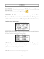
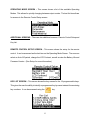
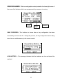
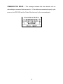
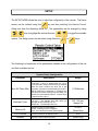
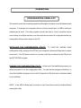
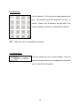
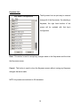
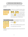
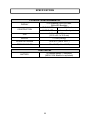
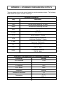
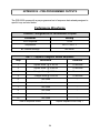
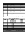
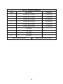
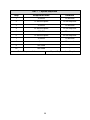
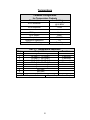
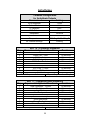
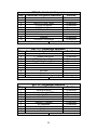
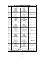
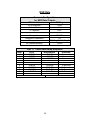
PROGRAMMABLE
PATIENT SIMULATOR
REMOTE CONTROL
WITH TRENDING
PSR-2200
USER MANUAL
BC BIOMEDICAL
PSR-2200
TABLE OF CONTENTS
WARNINGS, CAUTIONS, NOTICES .............................................................................. ii
DESCRIPTION ............................................................................................................... 1
LAYOUT ......................................................................................................................... 2
KEYS.............................................................................................................................. 3
SCREENS ...................................................................................................................... 5
MESSAGES ................................................................................................................... 7
SETUP ......................................................................................................................... 10
OPERATIONS.............................................................................................................. 11
CONFIGURATION USING A PC .................................................................... 11
CONTROLLING A PATIENT SIMULATOR ..................................................... 18
POWER .......................................................................................................... 20
MANUAL REVISIONS .................................................................................................. 21
LIMITED WARRANTY ................................................................................................. 21
SPECIFICATIONS ....................................................................................................... 22
APPENDIX A – STANDARD CONFIGURATION OUTPUTS ....................................... 23
APPENDIX B – PRE-PROGRAMMED OUTPUTS....................................................... 24
NOTES ......................................................................................................................... 38
This User Manual covers the following units:
PSR-2200
i
WARNING - USERS
The PSR-2200 is for use by skilled technical
personnel only.
WARNING - USE
The PSR-2200 is intended for testing only and
should never be used in diagnostics, treatment
or any other capacity where it would come in
contact with a patient.
WARNING - CONNECTIONS
All connections to patients must be removed
before connecting the DUT to the Patient
Simulator and PSR-2200. A serious hazard may
occur if the patient is connected when testing
with the Patient Simulator & PSR-2200.
CAUTION - MODIFICATIONS
The PSR-2200 is intended for use within the
published specifications. Any application
beyond these specifications or any unauthorized
user modifications may result in hazards or
improper operation.
CAUTION - SERVICE
The PSR-2200 is intended to be serviced only by
authorized service personnel. Troubleshooting
and service procedures should only be
performed by qualified technical personnel.
CAUTION - INSPECTION
The PSR-2200 should be inspected before each
use for obvious signs of abuse or wear. The
PSR-2200 should not be used and should be
serviced if any parts are in question.
ii
CAUTION - CLEANING
Do not immerse. The PSR-2200 should be
cleaned by wiping gently with a damp, lint-free
cloth. A mild detergent can be used if desired.
CAUTION - LIQUIDS
Do not submerge or spill liquids on the
PSR-2200. Do not operate the PSR-2200 if it may
have been exposed to fluid.
CAUTION - ENVIRONMENT
Exposure to environmental conditions outside
the specifications can adversely affect the
performance of the PSR-2200. Allow the PSR2200 to acclimate to specified conditions for at
least 30 minutes before attempting to operate it.
NOTICE – ABBREVIATIONS
ANSI
American National Standards Institute
BPM
Beats Per Minute
C
Celsius
°
degree(s)
DUT
Device Under Test
ECG
Electrocardiogram
F
Fahrenheit
Hz
hertz
IEC
International Electrotechnical Commission
Lbs
pounds
LED
Light Emitting Diode
mm
millimeter(s)
mV
millivolt(s)
NEDA
USA
V
National Electronic Distributors Association
United States of America
Volt(s)
iii
NOTICE – DISCLAIMER
BC GROUP INTERNATIONAL, INC. WILL NOT BE RESPONSIBLE
FOR ANY INJURIES SUSTAINED DUE TO UNAUTHORIZED
EQUIPMENT MODIFICATIONS OR APPLICATION OF EQUIPMENT
OUTSIDE OF THE PUBLISHED INTENDED USE AND
SPECIFICATIONS.
NOTICE – DISCLAIMER
BC GROUP INTERNATIONAL, INC. RESERVES THE RIGHT TO
MAKE CHANGES TO ITS PRODUCTS OR SPECIFICATIONS AT
ANY TIME, WITHOUT NOTICE, IN ORDER TO IMPROVE THE
DESIGN OR PERFORMANCE AND TO SUPPLY THE BEST
POSSIBLE PRODUCT. THE INFORMATION IN THIS MANUAL HAS
BEEN CAREFULLY CHECKED AND IS BELIEVED TO BE
ACCURATE. HOWEVER, NO RESPONSIBILITY IS ASSUMED FOR
INACCURACIES.
NOTICE – CONTACT INFORMATION
BC BIOMEDICAL
BC GROUP INTERNATIONAL, INC.
3081 ELM POINT INDUSTRIAL DRIVE
ST. CHARLES, MO 63301
USA
1-800-242-8428
1-314-638-3800
www.bcgroupintl.com
[email protected]
PSR-2200 User Manual
www.bcgroupintl.com
09/12
Copyright © 2012
Made in the USA
Rev 07
iv
BC BIOMEDICAL
PSR-2200
PATIENT SIMULATOR REMOTE CONTROL
The Model PSR-2200 is a Microprocessor based remote control for use with the BC
Biomedical PS-2200 Series of Patient Simulators. The remote allows the user to configure
the patient simulator and provides pre-programmed configurations as well as
programmable key functions and key sequences.
The following are highlights of some of the main features:
10 FIXED FUNCTION KEYS
18 PROGRAMMABLE FUNCTION KEYS
PROGRAMMABLE KEY NAMES UP TO 20 CHARACTERS
10 STEP KEY SEQUENCE PROGRAMMABILITY
UP TO 30 HOURS WORTH OF TRENDING CAPABILITY
PC INTERFACE FOR SIMPLE CONFIGURATION
LARGE GRAPHICS DISPLAY WITH CURSOR SELECTION OF
OPTIONS AND SETUP OF PARAMETERS
DISPLAY BACKLIGHT WITH ADJUSTABLE TIMER
BATTERY LIFE DISPLAY (0 TO 100%)
SOFTWARE ADJUSTABLE CONTRAST
PROGRAMMABLE AUTO SHUTDOWN TO CONSERVE
BATTERY LIFE
FLASH UPGRADEABLE FOR EASY FIRMWARE UPDATES IN THE
FIELD
CUSTOM PROGRAMMABLE FOR LARGE-VOLUME
REQUIREMENTS
ACCESSORIES:
BC20 - 41342
COMMUNICATION CABLE (Mini Din F to DB9 F)
(For PC to Remote Programming)
OPTIONAL ACCESSORIES:
BC20 - 41338
BC20 - 41339
COMMUNICATION CABLE (Mini DIN F to DB9 M)
(For remote to MPS-450 or Marq III)
COMMUNICATION CABLE ADAPTER (USB to DB9 M)
(For use with BC20-41337)
1
LAYOUT
This section looks at the layout of the PSR-2200 gives descriptions of the elements that
are present.
20 Dual Purpose Light
Touch Keys
10 keys for control and
configuration.
LCD Graphical
Display with
Backlight:
Shows configuration
and output setup.
10 Fixed function keys
18 Programmable keys
25’ Coiled Cable
For connection to a PC or
Patient Simulator
2
KEYS
20 soft touch keys are provided for system operation:
– Pressing and holding this key for 3 seconds will turn the unit off. Pressing and
releasing this key will toggle NUM LOCK MODE. Num Lock mode is identified by a ‘NUM’
icon in the upper right corner of the screen.
– These keys will change the selected item on the screen. The selected
item will be highlighted.
– In the SELECT MODE, if a parameter has been highlighted, these keys
with scroll through the available settings.
– This key allows the user to exit the Choices Menu or cancel a selection that has
not been entered.
– This key selects a changed option.
– This key is used to show a list of available choices for the selected setting.
– This key toggles the display mode. The available display modes are ECG
Output, Blood Pressure Output and Operating Mode.
3
– These are 10 fixed function keys that configure the Patient
Simulator for a pre-defined output configuration.
NOTE: The default outputs can be adjusted using the PSR2200 keys described above (See the CONTROLLING A
PATIENT SIMULATOR Section on page 20 for more details).
(See APPENDIX A – STANDARD CONFIGURATION
OUTPUTS for a description of the default outputs of these
keys.)
–
These are user-defined keys that are accessed via the
NUM LOCK MODE. Num Lock is toggled by pressing the
key.
NOTE:
The PSR-2200 has been pre-configured with a
default set of NUM LOCK programmed outputs. Each of
these is a programmed sequence (See the TRENDING
CAPABILITIES Section on page 16 for more details).
(See APPENDIX B – PRE-PROGRAMMED OUTPUTS for a
listing of these pre-programmed keys.)
–
This key displays the user-defined keys by Keyname. Keynames are
programmable via the computer interface.
4
SCREENS
MAIN SCREENS – There are three main screens: ECG, Blood Pressure and Operating
Mode. The available screens can be toggled using
.
ECG SCREEN – The ECG screen shows the current operating mode of the Patient
Simulator as well as the parameters that are available for that mode. Operating modes
available to the remote control are ECG, Arrhythmias, Pacemaker, Performance,
Fetal/Maternal and Cardiac Output.
BLOOD PRESSURE SCREEN – The Blood Pressure screen shows the output settings for
the Patient Simulator Invasive Blood Pressure Output.
NOTE: Not all patient simulators have four blood pressure channels. Changes made to
blood pressure channels that are not present on the patient simulator will not affect the
performance or operation of the patient simulator.
NOTE: Blood Pressure is not active for all operating modes.
5
OPERATING MODE SCREEN – This screen shows a list of the available Operating
Modes. This allows for quickly changing between output modes. The last list item allows
for access to the Remote Control Setup screen.
ADDITIONAL SCREENS – There are two additional screens: Remote Control Setup and
Key List.
REMOTE CONTROL SETUP SCREEN – This screen shows the setup for the remote
control. It can be accessed as the last item on the Operating Mode Screen. The user can
select an Auto-Off period, change the LCD Contrast, as well as view the Battery Life and
Firmware Version. (See Setup for more information.)
KEY LIST SCREEN – This screen shows the key names for the 18 programmable keys.
This gives the user the ability to identify a programmed key by name instead of memorizing
key numbers. It can be accessed using the
6
key.
MESSAGES
Several status messages are available to indicate the present state of the system. The
following is a brief description of the available messages:
NUM LOCK – This is a small graphic overlay located in the upper right corner of the screen
that indicates that the remote is in NUM LOCK MODE and any further key entry will
activate the user programmed key configuration.
KEY NUMBER– This is a small graphic overlay located in the lower right corner of the
screen that indicates which user programmed key function has been loaded.
7
SEQUENCE NUMBER– This is a small graphic overlay located in the lower right corner of
the screen that indicates which user programmed key sequence is running.
Key
Number
Sequence
Step
Time until
next step
SAVE PROGRESS– This indicator is shown when a key configuration has been
successfully sent from the PC. During this process, the key configuration data is being
stored to non-volatile memory in the remote control.
LOW BATTERY – This message indicates that the batteries are low and should be
replaced.
8
COMMUNICATION ERROR – This message indicates that the simulator did not
acknowledge a command that was sent to it. If the cables are connected properly, cycle
power on the PSR-2200 and the Patient Simulator and try the command again.
9
SETUP
The SETUP MODE allows the user to adjust the configuration of the remote. The Setup
screen can be entered using the
key and then selecting the Remote Control
Setup item from the Operating Mode list. The parameters can be changed by using
keys to highlight the desired line and
options. The Setup screen can be exited using either the
to toggle the available
or
keys.
The following is a breakdown of the parameters available in the configuration of the unit
and their available options:
System Setup Configuration
Parameter
Auto Off Timer (Min)
Backlight Timer
Battery Life
LCD Contrast
Software
Description
Determines the period of inactivity before the unit is
turned OFF. A timer is started when the unit is
turned ON and is reset each time a key is pressed.
When the timer reaches the value set in this
parameter, the power is automatically turned OFF.
(NOTE: Setting this parameter to 0 disables the
Auto Off timer. When running from line power, the
unit does not automatically shut off. Auto Off timer
is inactive during a test.)
Off – Always off
1-20 sec – The elapsed time after which the
backlight will automatically turn off.
Always ON – The backlight will be on
Displays current life of the battery.
At 10%, a warning screen will appear.
At 0%, the unit will power down automatically.
Sets the contrast of the display screen.
Displays current software program.
10
Range
0-30 Minutes
Off, 1-20 sec,
Always On
0-100%
(Read Only)
0-20
(Read Only)
OPERATIONS
CONFIGURATION USING A PC
The remote control can be easily programmed through a serial port on any Windows-based
computer. For laptops and computers that do not have a serial port, a USB to serial port
adapter can be used. This utility program can also be used to “clone” a specific remote
control setup to multiple remotes, once the initial remote control is configured and the key
configuration file has been stored to the PC.
INSTALLING THE CONFIGURATION UTILITY:
To install the windows based
configuration utility, simply put the CD into your computer’s drive and follow the on-screen
instructions. If the CD does not auto-run, browse to the files contained on the CD and run
the SETUP.EXE program.
RUNNING THE CONFIGURATION UTILITY: At the end of the installation process, you
will be prompted to run the configuration utility. You can start the program at this time, or
close the installation program and run the Configuration Utility from an icon that was added
to your desktop.
NOTE: If the USB to Serial port converter is used, the drivers must be installed before
running the utility.
11
MAIN CONFIGURATION SCREEN (AT A GLANCE):
This section is utilized to program a key sequence. To
end a sequence, set the last step’s time delay to 0.
Use this
section of
the screen
to view or
change the
configuration of
the Patient
Simulator
for the
selected
Key.
Use these
buttons to
select a
key to
configure
Use this
section to
select a
key as
single
function or
sequence,
and to
name the
key.
History of
key configuration
files.
Model
Identification
of remote.
Task Progress Indicator
Status message
Current Time
Today’s Date
Com Port being used
12
Key Selection:
Use the buttons 1-18 to select a programmable remote
key. The selected key will be depressed, as key 1 is
shown. When a key is selected, the right half of the
screen changes to show the configuration of that key.
LIST: This key is used to view/edit the Keynames.
Key Information:
This box allows the user to select whether a key will
perform a single function or run a sequence of functions
and to view/edit the Keyname.
13
Key Sequence:
When a key is set to run a sequence, this window is used to program
each step of the sequence, the delay between each step and the action
to be taken at the end of the sequence. Each step can be programmed
to a specific Operating Mode. The delay between steps is
programmable from 1 to 600 seconds. If any step delay is set to 0
seconds, the sequence will end at that step. At the end of the
sequence, the remote can be set to halt at the current setting or to jump
to a specific programmable key. Nested sequences can be performed
by programming multiple key sequences and having the end of one
sequence jump to another.
Trending Capabilities:
Through the use of Key Sequences, the PSR-2200 is capable of running an endless loop
of trended patient physiological data. The 18 separate programmable keys, each of which
can be programmed with unique waveform outputs for up to 600 seconds each, can be
“daisy-chained” to create a trending pattern with up to 180 unique steps and with a total
trend duration of up to 108,000 seconds (30 hours) worth of waveform data.
The PSR-2200 comes with a pre-programmed set of sequence data already assigned to
specific keys as listed in Appendix B PRE-PROGRAMMED OUTPUTS.
14
Control Buttons:
Read Remote: This button is used to read the current settings in the remote.
Download To Remote:
This button is used to update the remote with the key
configurations shown on the screen.
Cancel Changes: This button cancels any changes that have been made to the selected
key configuration. Once a new key is selected, the changes cannot be canceled.
Edit Key Name List: This button is used to show the Keyname list window, which shows a
list of all of the Keynames.
Load Key Config File: This button is used to open a key configuration file that has been
saved on the computer. As files are opened, they are added to the Current Key Config File
history for quick future reference. If changes have been made to an open file, you will be
prompted to save them before loading a new file.
Save Key Config File: This button is used to save the current key settings to a file on the
computer.
Current Key Config File: This is a listing of the previous config files that have been
opened. Selecting a file from the list will cause it to open. If changes have been made to
an open file, you will be prompted to save them before loading a new file.
15
Keyname List:
The Keyname List is a quick way to view and
change all of the Keynames. By selecting a
Keyname, the right hand section of the
screen will be updated with that key’s
configuration.
Save: This button is used to accept any changes made to the Keynames and the close
the Keyname screen.
Cancel: This button is used to close the Keyname screen without saving any Keyname
changes that were made.
NOTE: Keynames are restricted to 20 characters.
16
Output Configuration:
This
section
shows
the
Patient
Simulator
configuration for the selected key. The buttons at the
bottom select the Output Mode. The dropdown lists
select the setting for each parameter available in the
selected output mode.
File Menu:
This menu allows you to load a key configuration file, save a
key configuration file, clear the loaded file list history or exit
the program.
Edit Menu:
The edit menu provides another way to access the Keyname
list.
17
CONTROLLING A PATIENT SIMULATOR
To control a patient simulator, the remote control is first plugged into the AUX connector of
the simulator.
PRE-DEFINED FUNCTIONS: A fixed function can be loaded by pressing the desired
key. To make adjustments to the output selections,
and
can be used to select and
modify output settings.
selected, the
When the desired output is
key is used to send the configuration
to the Patient Simulator. Any changes made on the remote
will be immediately made on the Patient Simulator.
USER PROGRAMMABLE FUNCTIONS: User programmable functions are accessed
through the NUM LOCK MODE. This mode is set by
pressing the
key.
NOTE: The NUM LOCK MODE is identified by the ‘NUM’
icon in the upper right corner of the screen.
To select a pre-programmed output, simply press the number of the output while in NUM
LOCK MODE.
18
The
key can be used to show the list of Keynames that correspond to the user-
programmable keys. With the List Mode, the user no longer has to remember which key
number corresponds to which Output Mode. The key number can be named and the name
is viewed through the Key List Mode. The
desired Output Mode and the
keys are used to select the
key is used to activate that output.
When a user-defined key is loaded, a small icon will appear in the lower right corner to
identify which key number is loaded.
Further modifications can be made to the simulator output by exiting the NUM LOCK
MODE and using the
and
keys to select and modify output
parameters. When the desired output is selected, the
configuration to the Patient Simulator.
key is used to send the
Any changes made on the remote will be
immediately made on the Patient Simulator.
PATIENT SIMULATOR MODE: The PATIENT SIMULATOR OUTPUT MODE (ECG,
Arrhythmia, Pacemaker, Performance, Fetal/Maternal, or Cardiac) can be selected easily
by pressing the
mode selected.
key to select the Operating Mode Menu with the current operating
The
desired Operating Mode and the
and
keys are used to select the
or
keys are used to activate the new
Output Mode.
POWER:
To turn the remote control off, hold the
key for 3 seconds.
19
SPECIAL CONFIGURATIONS AVAILABLE:
The PSR-2200 is a unique and extremely versatile instrument, capable of many different
configurations. This capability allows for custom configurations for our large-volume
customers who desire a dedicated and functionally unique remote control for their patient
simulator fleet. If you have special requirements on a large-scale (typically 50 units or
more), please feel free to contact us regarding your needs.
POWER
The PSR-2200 is designed for use with a standard 9V Alkaline battery. Additionally, the
PSR-2200 can also get power from the PS-2200. With the use of a battery eliminator on
the PS-2200, the PSR-2200 can operate indefinitely.
20
MANUAL REVISIONS
Revision #
Program #
Revisions Made
Rev 01
Rev 02
Rev 03
Rev 04
Rev 05
Rev 06
Rev 07
DT7349CA
DT7349CA
DT7349CA
DT7349CA
DT7349CC
DT7349CC
DT7349CD
Preliminary Manual
Pre-Programmed Outputs Added
Appendices Added
Power Information Added
Added Backlight
Accessories Updated
Manual Format Updated
LIMITED WARRANTY
WARRANTY: BC GROUP INTERNATIONAL, INC. WARRANTS ITS NEW PRODUCTS TO BE FREE
FROM DEFECTS IN MATERIALS AND WORKMANSHIP UNDER THE SERVICE FOR WHICH THEY
ARE INTENDED. THIS WARRANTY IS EFFECTIVE FOR TWELVE MONTHS FROM THE DATE OF
SHIPMENT.
EXCLUSIONS: THIS WARRANTY IS IN LIEU OF ANY OTHER WARRANTY EXPRESSED OR
IMPLIED, INCLUDING, BUT NOT LIMITED TO ANY IMPLIED WARRANTY OF MERCHANTABILITY
OR FITNESS FOR A PARTICULAR PURPOSE.
BC GROUP INTERNATIONAL, INC. IS NOT LIABLE FOR ANY INCIDENTAL OR CONSEQUENTIAL
DAMAGES.
NO PERSON OTHER THAN AN OFFICER IS AUTHORIZED TO GIVE ANY OTHER WARRANTY OR
ASSUME ANY LIABILITY.
REMEDIES: THE PURCHASER'S SOLE AND EXCLUSIVE REMEDY SHALL BE: (1) THE REPAIR OR
REPLACEMENT OF DEFECTIVE PARTS OR PRODUCTS, WITHOUT CHARGE. (2) AT THE OPTION
OF BC GROUP INTERNATIONAL, INC., THE REFUND OF THE PURCHASE PRICE.
P:\MANUALS\BCGroup\…\PSR-2200\PSR-2200_UM_Rev07.doc
21
SPECIFICATIONS
PHYSICAL & ENVIRONMENTAL
DISPLAY
CONSTRUCTION
SIZE
LCD Graphical 128 X 64 Pixels,
White LED Backlight
ENCLOSURE
ABS Plastic
FACE PLATE
Lexan, Back printed
5.98 x 3.27 x 1.28 Inches
(151.9 x 83.1 x 32.5 mm)
WEIGHT
< 1 Lbs (0.45 kg)
OPERATING RANGE
15 to 40 °C (59 to 104 °F)
STORAGE RANGE
-20 to 65 °C (-4° to 149 °F)
ELECTRICAL
BATTERY
9V Alkaline Battery (1 Required)
(NEDA 1604 Alkaline or equivalent)
22
APPENDIX A – STANDARD CONFIGURATION OUTPUTS
There are eleven keys on the remote labeled to provide standard outputs. The following
tables detail the outputs for each of the keys:
Standard Outputs
Key
Waveform
NSR
Normal Sinus Rhythm @ 80 BPM
Tachy
Normal Sinus Rhythm @ 160 BPM
Brady
Normal Sinus Rhythm @ 30 BPM
Ventricular Arrhthmias
Asystole
Supraventricular Arrhythmias
Atrial Flutter
Supraventricular Arrhythmias
Atrial Finrillation – Coarse
Supraventricular Arrhythmias
Ventricular Fibrillation - Coarse
Ventricular Arrhythmias
Ventricular Tachycardia
Premature Arrythmias
Atrial PAC-Auto
Premature Arrythmias
PVC 1 – Auto
Premature Arrythmias
PVC 2 – Auto
Asyst
A-Flutter
A-Fib
V-Fib
V-Tach
PAC
PVC1
PVC2
Common Configuration for Standard Outputs
Parameter
Setting
ECG Amplitude
1.0 mV
Patient Mode
Adult
ST Segment
0 mV
ECG Artifact
None
Respiration
30 BrPM
Respiration Resistance
1Ω
Temperature
37° C
98.6° F
BP Channel Settings
0 mmHg
23
APPENDIX B – PRE-PROGRAMMED OUTPUTS
The PSR-2200 comes with a pre-programmed set of sequence data already assigned to
specific keys as listed below:
Performance Waveforms
Common Configuration for Performance Outputs
Parameter
Setting
ECG Amplitude
1.0 mV
Temperature
30.0° C / 86.0° F
BP Channel Settings
Not Active
KEY 1 – Square/Triangular Waves Sequence
Step
Waveform
Duration
1
Square Wave @ 0.125 Hz
10 seconds
2
Square Wave @ 2.000 Hz
10 seconds
3
Triangle Wave @ 2.000 Hz
10 seconds
4
Triangle Wave @ 2.500 Hz
10 seconds
5
Not Used
-
6
Not Used
-
7
Not Used
-
8
Not Used
-
9
Not Used
-
10
Not Used
-
End of Sequence Action
Repeat Sequence from Step 1
24
KEY 2 – Sine Waves Sequence
Step
Waveform
Duration
1
Sine Wave @ 0.1 Hz
10 seconds
2
Sine Wave @ 0.5 Hz
10 seconds
3
Sine Wave @ 5.0 Hz
10 seconds
4
Sine Wave @ 10 Hz
10 seconds
5
Sine Wave @ 40 Hz
10 seconds
6
Sine Wave @ 50 Hz
10 seconds
7
Sine Wave @ 60 Hz
10 seconds
8
Sine Wave @ 100 Hz
10 seconds
9
Not Used
-
10
Not Used
-
End of Sequence Action
Repeat Sequence from Step 1
KEY 3 – Pulse Wave Sequence
Step
Waveform
Duration
1
Pulse Wave @ 30 BPM
10 seconds
2
Pulse Wave @ 60 BPM
10 seconds
3
Pulse Wave @ 120 BPM
10 seconds
4
Not Used
-
5
Not Used
-
6
Not Used
-
7
Not Used
-
8
Not Used
-
9
Not Used
-
10
Not Used
-
End of Sequence Action
Repeat Sequence from Step 1
25
KEY 4 – R-Wave Sequence
Step
Waveform
Duration
1
R-Wave @ 30 BPM
10 seconds
2
R-Wave @ 60 BPM
10 seconds
3
R-Wave @ 80 BPM
10 seconds
4
R-Wave @ 120 BPM
10 seconds
5
R-Wave @ 200 BPM
10 seconds
6
R-Wave @ 250 BPM
10 seconds
7
Not Used
-
8
Not Used
-
9
Not Used
-
10
Not Used
-
End of Sequence Action
Repeat Sequence from Step 1
26
Blood Pressure
Common Configuration for Blood Pressure Outputs
Parameter
Setting
ECG Waveform
Normal Sinus Rhythm
@ 80 BPM
ECG Amplitude
1.0 mV
Patient Mode
Adult
ST Segment
0 mV
ECG Artifact
None
Respiration
30 BrPM
Respiration Resistance
1Ω
Temperature
37.0° C / 98.6° F
KEY 5 – Blood Pressure Sequence
Step
BP Channels
Waveform
1
All
Static
0 mmHg
10 seconds
2
All
Static 20 mmHg
10 seconds
3
All
Static 40 mmHg
10 seconds
4
All
Static 60 mmHg
10 seconds
5
All
Static 100 mmHg
10 seconds
6
All
Static 150 mmHg
10 seconds
7
All
Static 200 mmHg
10 seconds
8
All
Static 250 mmHg
10 seconds
9
All
Static 300 mmHg
10 seconds
10
All
Static 400 mmHg
10 seconds
End of Sequence Action
Duration
Repeat Sequence from Step 1
27
Respiration
Common Configuration for Respiration Outputs
Parameter
Setting
ECG Waveform
Normal Sinus Rhythm
@ 80 BPM
ECG Amplitude
1.0 mV
Patient Mode
Adult
ST Segment
0 mV
ECG Artifact
None
Respiration Resistance
1Ω
Temperature
37.0° C / 98.6° F
BP Channel Settings
0 mmHg
KEY 6 – Respiration Sequence
Step
Respiration Rate
Duration
1
0 BrPM Apnea
10 seconds
2
15 BrPM
10 seconds
3
20 BrPM
10 seconds
4
30 BrPM
10 seconds
5
40 BrPM
10 seconds
6
60 BrPM
10 seconds
7
80 BrPM
10 seconds
8
100 BrPM
10 seconds
9
120 BrPM
10 seconds
10
Not Used
-
End of Sequence Action
Repeat Sequence from Step 1
28
KEY 7 – Apnea Sequence
Step
Respiration Rate
Duration
1
30 BrPM
30 seconds
2
12 Second Apnea
30 sec step time
3
30 BrPM
30 seconds
4
22 Second Apnea
30 sec step time
5
30 BrPM
30 seconds
6
32 Second Apnea
60 sec step time
7
30 BrPM
10 seconds
8
Apnea
15 seconds
9
Not Used
-
10
Not Used
-
End of Sequence Action
Repeat Sequence from Step 1
29
ECG Artifact
Common Configuration for Artifact Outputs
Parameter
Setting
ECG Waveform
Normal Sinus Rhythm
@ 80 BPM
ECG Amplitude
1.0 mV
Patient Mode
Adult
ST Segment
0 mV
Respiration
30 BrPM
Respiration Resistance
1Ω
Temperature
37.0° C / 98.6° F
BP Channel Settings
0 mmHg
KEY 8 – ECG Artifact Sequence
Step
Artifact
Duration
1
None
15 seconds
2
50 Hz Noise
15 seconds
3
60 Hz Noise
15 seconds
4
Muscle
15 seconds
5
Baseline Wander
15 seconds
6
Respiration
15 seconds
7
Not Used
-
8
Not Used
-
9
Not Used
-
10
Not Used
-
End of Sequence Action
Repeat Sequence from Step 1
30
Temperature
Common Configuration
for Temperature Outputs
Parameter
Setting
Normal Sinus Rhythm
@ 80 BPM
1.0 mV
Adult
0 mV
None
30 BrPM
1Ω
0 mmHg
ECG Waveform
ECG Amplitude
Patient Mode
ST Segment
ECG Artifact
Respiration
Respiration Resistance
BP Channel Settings
Step
1
2
3
4
5
6
7
8
9
10
KEY 9 – Temperature Sequence
Temperature
Duration
0 Deg C / 32.0 Deg F
15 seconds
24 Deg C / 75.2 Deg F
15 seconds
30 Deg C / 86.0 Deg F
15 seconds
35 Deg C / 95.0 Deg F
15 seconds
37 Deg C / 98.6 Deg F
15 seconds
40 Deg C / 104.0 Deg F
15 seconds
42 Deg C / 107.6 Deg F
15 Seconds
Not Used
Not Used
Not Used
End of Sequence Action
Repeat Sequence from Step 1
31
Arrhythmias
Common Configuration
for Arrhythmia Outputs
Parameter
Setting
ECG Amplitude
Patient Mode
ST Segment
ECG Artifact
Respiration
Respiration Resistance
Temperature
BP Channel Settings
Step
1
2
3
4
5
6
7
8
9
10
KEY 10 – Premature Sequence
Premature Arrhythmia Waveform
Duration
Atrial PAC – Auto
60 seconds
Nodal PNC – Auto
60 seconds
PVC 1 – Auto
60 seconds
PVC 1 Early – Auto
60 seconds
PVC 1 R on R – Auto
60 seconds
PVC 2 – Auto
60 seconds
PVC 2 Early – Auto
60 seconds
PVC R on T – Auto
60 seconds
Multifocal PVC – Auto
60 seconds
Not Used
End of Sequence Action
Repeat Sequence from Step 1
Step
1
2
3
4
5
6
7
8
9
10
1.0 mV
Adult
0 mV
None
30 BrPM
1Ω
37.0 Deg C / 98.6 Deg F
0 mmHg
KEY 11 – Supraventricular Sequence
Supervent Arrhythmia Waveform
Duration
Atrial Fibrillation – Course
60 seconds
Atrial Fibrillation – Fine
60 seconds
Atrial Flutter
60 seconds
Atrial Tachycardia
60 seconds
Paroxysmal Atrial Tachycardia
60 seconds
Supraventricular Tachycardia
60 seconds
Sinus Arrhythmia
60 seconds
Missed Beat – Auto
60 seconds
60 seconds
Missed Beat – Manual
Nodal Rhythm
60 seconds
End of Sequence Action
Repeat Sequence from Step 1
32
Step
1
2
3
4
5
6
7
8
9
10
Pair of PVCs – Auto
60 seconds
Run of 5 PVCs – Auto
60 seconds
Run of 11 PVCs – Auto
60 seconds
6 PVCs per Minute
60 seconds
12 PVCs per Minute
60 seconds
24 PVCs per Minute
60 seconds
Frequent Multifocal PVCs
60 seconds
Bigeminy
60 seconds
Trigeminy
60 seconds
Ventricular Tachycardia
60 seconds
End of Sequence Action
Repeat Sequence from Step 1
Step
1
2
3
4
5
6
7
8
9
10
KEY 13 – Conduction Sequence
Conduction Arrhythmia Waveform
Duration
1st Degree Heart Block
60 seconds
2nd Degree Heart Block
60 seconds
rd
3 Degree Heart Block
60 seconds
Right Bundle Branch Block
60 seconds
Left Bundle Branch Block
60 seconds
Not Used
Not Used
Not Used
Not Used
Not Used
End of Sequence Action
Repeat Sequence from Step 1
Step
1
2
3
4
5
6
7
8
9
10
KEY 12 – Ventricular Sequence
Ventricular Arrhythmia Waveform
Duration
KEY 14 – Pacemaker Sequence
Pacemaker Waveform
Duration
Atrial @ 80 BPM
60 seconds
Asynchronous @ 75 BPM
60 seconds
Non-Capture
60 seconds
Non- Function
60 seconds
Demand – Occasional
60 seconds
Demand – Frequent
60 seconds
AV Sequential
60 seconds
Not Used
Not Used
Not Used
End of Sequence Action
Repeat Sequence from Step 1
33
Fetal / Maternal
Common Configuration
for Fetal / Maternal Outputs
Parameter
Setting
Maternal ECG
Fetal ECG
Trigger Mode
Step
1
2
3
4
5
6
7
8
9
10
80 BPM
120 BPM
2 Minutes
KEY 15 – Fetal / Maternal Sequence
IUP Simulation
Duration
Uniform Deceleration
360 seconds
Early Deceleration
360 seconds
Late Deceleration
360 seconds
Uniform Acceleration
360 seconds
Not Used
Not Used
Not Used
Not Used
Not Used
Not Used
End of Sequence Action
Repeat Sequence from Step 1
Sick Patient
Common Configuration
for Sick Patient Outputs
Parameter
Setting
ECG Amplitude
Patient Mode
Respiration Resistance
1.0 mV
Adult
1Ω
34
Step
1
2
3
4
5
6
7
8
9
10
KEY 16 – Sick Patient 1 Sequence
IUP Simulation
Duration
Heart Rate
ST Elevation
Artifact
Respiration
Temperature
BP Channel 1
Heart Rate
ST Elevation
Artifact
Respiration
Temperature
BP Channel 1
Heart Rate
ST Elevation
Artifact
Respiration
Temperature
BP Channel 1
Heart Rate
ST Elevation
Artifact
Respiration
Temperature
BP Channel 1
Heart Rate
ST Elevation
Artifact
Respiration
Temperature
BP Channel 1
Heart Rate
ST Elevation
Artifact
Respiration
Temperature
BP Channel 1
Heart Rate
ST Elevation
Artifact
Respiration
Temperature
BP Channel 1
Heart Rate
ST Elevation
Artifact
Respiration
Temperature
BP Channel 1
90 BPM
0.1 mV
None
40 BrPM
35 Deg C/95 Deg F
120/80
100 BPM
0.0 mV
Respiration
40 BrPM
40 Deg C/104 Deg F
120/80 w/5 mm artifact
120 BPM
0.5 mV
Baseline Wander
60 BrPM
40 Deg C/104 Deg F
120/80 w/10 mm artifact
140 BPM
0.4 mV
Muscle
60 BrPM
42 Deg C/104 Deg F
120/80 w/10 mm artifact
180 BPM
0.8 mV
Baseline Wander
80 BrPM
40 Deg C/104 Deg F
120/80 w/16 mm artifact
140 BPM
0.4 mV
None
60 BrPM
40 Deg C/104 Deg F
120/80 w/10 mm artifact
100 BPM
0.1 mV
Baseline Wander
40 BrPM
35 Deg C/95 Deg F
120/80
90 BPM
0.1 mV
None
40 BrPM
35 Deg C/95 Deg F
120/80
Not Used
Not Used
End of Sequence Action
35
60 seconds
15 seconds
30 seconds
10 seconds
15 seconds
15 seconds
15 seconds
15 seconds
-
Repeat Sequence from Step 1
NSR Rate
Common Configuration
for NSR Rate Outputs
Parameter
Setting
ECG Amplitude
Patient Mode
ST Segment
ECG Artifact
Respiration
Respiration Resistance
Temperature
BP Channel Settings
Step
1
2
3
4
5
6
7
8
9
10
1.0 mV
Adult
0 mV
None
30 BrPM
1Ω
37.0 Deg C / 98.6 Deg F
120/80
KEY 17 – NSR Rate Ramp Sequence
ECG
Respiration
Duration
20 BPM
40 BPM
45 BPM
60 BPM
80 BPM
90 BPM
100 BPM
120 BPM
140 BPM
180 BPM
End of Sequence Action
15 BrPM
15 seconds
20 BrPM
15 seconds
40 BrPM
15 seconds
60 BrPM
15 seconds
80 BrPM
15 seconds
80 BrPM
15 seconds
100 BrPM
15 Seconds
120 BrPM
15 Seconds
120 BrPM
15 Seconds
120 BrPM
15 Seconds
Repeat Sequence from Step 1
36
Ventricular Fibrillation
Common Configuration
for V-Fib Outputs
Parameter
Setting
ECG Amplitude
Patient Mode
ST Segment
ECG Artifact
Respiration
Respiration Resistance
Temperature
BP Channel Settings
Step
1
2
3
4
5
6
7
8
9
10
1.0 mV
Adult
0 mV
None
30 BrPM
1Ω
37.0 Deg C / 98.6 Deg F
0 mmHg
KEY 18 – V-Fib Sequence
Waveform
Duration
NSR @ 80 BPM
30 seconds
Run of 5 PVCs
30 seconds
NSR @ 80 BPM
30 seconds
Run of 11 PVCs
30 seconds
Ventricular Tachycardia
15 seconds
Ventricular Fibrillation – Course
10 seconds
Ventricular Fibrillation – Fine
10 seconds
Asystole
10 seconds
Not Used
Not Used
End of Sequence Action
Repeat Sequence from Step 1
37
NOTES
38
NOTES
39
NOTES
40
BC GROUP INTERNATIONAL, INC.
3081 ELM POINT INDUSTRIAL DRIVE
ST. CHARLES, MO 63301
USA
1-800-242-8428
1-314-638-3800
www.bcgroupintl.com
[email protected]
PSR-2200 User Manual
09/12 – Rev 07
Copyright © 2012
Made in the USA