1
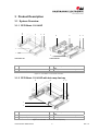
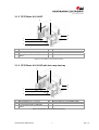
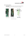
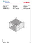
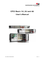
CPCI Basic 1U, 2U and 4U User's Manual www.hartmann-elektronik.de Rev. 1.2 Rev: R 1.0 R 1.1 R 1.2 Date: 19.04.2010 09.08.2011 25.06.2012 Impressum: Hartmann Elektronik GmbH Motorstraße 43, D-70499 Stuttgart (Weilimdorf) Telefon + 49 711 1 39 89-0 Telefax + 49 711 8 66 11 91 E-mail info @ hartmann-elektronik.de Internet www.hartmann-elektronik.de Hartmann Elektronik is a longstanding partner of the embedded industry and has a variety of different backplanes. With our wide selection of backplanes and enclosure you can build your perfect system platform Copyright © 2012 All rights and technical modifications reserved. www.hartmann-elektronik.de I Rev. 1.2 Table of Contents 1 2 3 4 5 Applicability ..................................................................................................................................... 1 1.1 Background Information ......................................................................................................... 1 Safety .............................................................................................................................................. 2 2.1 Intended Application............................................................................................................... 2 2.2 Safety Symbols ...................................................................................................................... 2 2.3 General Safety Precautions ................................................................................................... 2 2.4 Safety Instructions.................................................................................................................. 3 2.4.1 Protection Against Electromagnetic Interference (EMI) ................................................ 3 2.4.2 Electrostatic Discharge Precautions.............................................................................. 3 2.4.3 Installation ..................................................................................................................... 3 2.4.4 Location ......................................................................................................................... 3 2.4.5 Voltage Hazards ............................................................................................................ 3 2.4.6 System Overheating ...................................................................................................... 3 2.4.7 Mounting Considerations ............................................................................................... 4 2.4.8 Electrical Hazards.......................................................................................................... 4 2.4.9 Board Installation ........................................................................................................... 4 Product Description......................................................................................................................... 5 3.1 System Overview ................................................................................................................... 5 3.1.1 CPCI Basic 1 U 84 HP .................................................................................................. 5 3.1.2 CPCI Basic 1 U 84 HP with hot swap fan tray .............................................................. 5 3.1.3 CPCI Basic 2 U 84 HP .................................................................................................. 6 3.1.4 CPCI Basic 2 U 84 HP with hot swap fan tray .............................................................. 6 3.1.5 CPCI Basic 4 U 84 HP .................................................................................................. 7 3.1.6 CPCI Basic 4 U 84 HP with hot swap fan tray .............................................................. 7 3.2 Subrack .................................................................................................................................. 8 3.3 Backplane............................................................................................................................... 8 3.3.1 Description..................................................................................................................... 8 3.3.2 Temperature sensors and fan control ........................................................................... 9 3.3.3 Temperatur range .......................................................................................................... 9 3.3.4 Fan signal connector ................................................................................................... 10 3.3.5 Backplane CPCI 9U 2 slot (6U) + 1 x PSU 47p (3U) .................................................. 11 3.3.6 Backplane CPCI 9U 3 slot (6U) + 1 x PSU 47p (3U) .................................................. 11 3.3.7 Backplane CPCI 9U 4 slot (6U) + 2 x PSU 47p (3U) .................................................. 12 3.3.8 Backplane CPCI 9U 8 slot (6U) + 4 x PSU 47p (3U) .................................................. 12 3.4 Electrical Connection and Power Supply ............................................................................. 13 3.4.1 Power Entry Module .................................................................................................... 13 3.4.2 Grounding/Protective Earthing .................................................................................... 14 3.4.3 Power Supply .............................................................................................................. 15 3.5 Cooling ................................................................................................................................. 17 3.5.1 Airflow .......................................................................................................................... 17 3.5.2 Fans ............................................................................................................................. 18 3.5.3 Air Filter ....................................................................................................................... 18 3.5.4 Fan Trays .................................................................................................................... 20 3.5.5 Fan Tray Interface ....................................................................................................... 21 Installation ..................................................................................................................................... 22 4.1 Subrack Components........................................................................................................... 22 4.1.1 Controls and Indicators ............................................................................................... 22 4.2 Inspecting the Subrack Components ................................................................................... 22 4.3 Protection Against Electromagnetic Interference ................................................................. 23 4.4 Preparing the Subrack ......................................................................................................... 23 4.4.1 Mounting the Subrack ................................................................................................. 23 4.4.2 Powering the Subrack ................................................................................................. 23 4.4.3 Installing Boards .......................................................................................................... 23 4.4.4 Installing Filler Panels ................................................................................................. 24 Maintaining the Subrack ............................................................................................................... 25 5.1 Replacing the Fan Tray ........................................................................................................ 25 5.2 Replacing the Air Filter ......................................................................................................... 25 www.hartmann-elektronik.de II Rev. 1.2 6 5.3 Replacing the Power Supply ................................................................................................ 26 Service .......................................................................................................................................... 27 6.1 Technical support and Return for Service Assistance ......................................................... 27 6.2 Declaration of Conformity..................................................................................................... 27 6.3 Scope of Delivery ................................................................................................................. 28 6.4 Subrack Specifications ......................................................................................................... 29 List of Figures Figure 3-1: CPCI Basic 1 U 84 HP with 3 DC fans ................................................................................. 5 Figure 3-2: CPCI Basic 1 U 84 HP with hot-swap fan try ........................................................................ 5 Figure 3-3: CPCI Basic 2 U 84 HP with 3 DC fans ................................................................................. 6 Figure 3-4: CPCI Basic 2 U 84 HP with hot-swap fan try ........................................................................ 6 Figure 3-5: CPCI Basic 4 U 84 HP with 6 DC fans ................................................................................. 7 Figure 3-6: CPCI Basic 4 U 84 HP with hot-swap fan try ........................................................................ 7 Figure 3-7: Pin assignment fan signal connector .................................................................................... 9 Figure 3-8 Dip-Switch .............................................................................................................................. 9 Figure 3-9 Fan characteristic dip-switch on/off...................................................................................... 10 Figure 3-10: Pin assignment fan signal connector ................................................................................ 10 Figure 3-11 Backplane CPCI 9U 2 slot (6U) + PSU 47p (3U) front / rear ............................................. 11 Figure 3-12 Backplane CPCI 9U 3 slot (6U) + PSU 47p (3U) front / rear ............................................. 11 Figure 3-13 Backplane CPCI 9U 4 slot (6U) + 2 x PSU 47p (3U) front / rear ....................................... 12 Figure 3-14 Backplane CPCI 9U 8 slot (6U) + 4 x PSU 47p (3U) front / rear ....................................... 12 Figure 3-15 Power Entry Module ........................................................................................................... 13 Figure 3-16 Protective Earth and Grounding......................................................................................... 14 Figure 3-17: AC Power Supply 3U, 250W ............................................................................................. 16 Figure 3-18 Air Flow .............................................................................................................................. 17 Figure 3-19 Fan Tray 1U ....................................................................................................................... 20 Figure 3-20 Fan Tray 2U ....................................................................................................................... 20 Figure 3-21 Fan Tray 4U ....................................................................................................................... 20 Figure 3-22 Fan Tray Interface .............................................................................................................. 21 Figure 4-1: Indicator Panel (sample: 2U version) .................................................................................. 22 Figure 4-2 AC Input (sample: 2U version) ............................................................................................. 23 Figure 5-1: Fan Tray Components (sample: 2U version) ...................................................................... 25 Figure 5-2: Air Filter Replacement (sample: 2U version) ...................................................................... 26 Figure 5-3 Replacing the Power Supply (sample: 2U version) ............................................................. 26 Rev. 1.2 III www.hartmann-elektronik.de 1 Applicability System name CPCI Basic 1 U 84 HP Depth 283 mm CPCI Basic 1 U 85 HP Depth 283 mm with 3 slot Backplane CPCI Basic 1 U 84 HP Depth 283 mm with fan tray CPCI Basic 2 U 84 HP Depth 283 mm CPCI Basic 2 U 84 HP Depth 283 mm with fan tray CPCI Basic 4 U 84 HP Depth 283 mm CPCI Basic 4 U 84 HP Depth 283 mm with fan tray Order number LMH0000190 LMH0000490 LMH0000300 LMH0000130 LMH0000220 LMH0000210 LMH0000250 1.1 Background Information User Manual Hartmann cPCI Backplanes Technical Data Hartmann CPCI Backplanes User Guide Hartmann CPCI Backplanes IEC 60297-3-101, -102, -103 PICMG 2.0 R3.0 CPCI Core Specification PICMG 2.01 R2.0 Hot Swap PICMG 2.09 R1.0 System Management Bus PICMG 2.10 R1.0 Keying IEC 1000-4-4 Electromagnetic Compatibility, Part 4, Section 4, Electrical fast transient/burst immunity test. EN60950-1 Shock: o MIL-STD-810F 1 January 2000 Annex C, U.S highway truck Figure 514.5C-1, vertical Shock test (Sawtooth) Figure 516.5-10 Vibration: o DIN EN 61373:1999, Figure 2, Category 1, Class B o MIL-STD-810F 1 January 2000 Annex C, Shipboard: Figure 514.5C-15 www.hartmann-elektronik.de 1 Rev. 1.2 2 Safety 2.1 Intended Application The CPCI System Platform Basic subracks is intended as a platform for a microcomputer system based on the CPCI Standard PICMG 2.0 R3.0. CPCI System Platform Basic subracks are not end-products, so there is no valid approval for this unit. In Order to enable stand-alone functionality, additional elements are required. An operational system is achieved only by way of appropiate CPCI boards. The completion and final testing of the units have been carried out, or at least supervised, by qualified technicians. These instructions are directed exclusively to these qualified technicians i.e.engineers, trained and qualified electricians etc. Make sure that the finished system complies with the safety regulations currently applicable in the country it is going to be used. 2.2 Safety Symbols Hazardous voltage! Familiarise yourself with the danger of electrical voltages and the safety precautions before starting to work with parts that carry dangerous voltages Caution! This symbol indicates a condition where damage of the equipment or injury of the service personnel could occur. To reduce the risk of damage or injury, follow all steps or procedures as instructed. Danger of electrostatic discharge! Static electricity can damage sensitive components in a system. To avoid damage, wear ESD wrist straps or at regular intervals touch blank enclosure parts. 2.3 General Safety Precautions Warning! Voltages over 60 VDC can be present in this equipment. This equipment is intended to be accessed, to be installed and maintained by qualified and trained service personnel only. This equipment is designed in accordance with protection class 1! lt must therefore be operated only with protective GND/earth connection! Rev. 1.2 2 www.hartmann-elektronik.de 2.4 Safety Instructions The intended audience of this User's Manual is system Integrators and hardware/software engineers. The product has been designed to meet relevant standard industrial safety requirements. It must not be used except in its specific area of office telecommunication industry and industrial control. It shall not be used in safety-critical applications, life-sustaining appliances or in aircraft. Only trained personnel or persons qualified in electronics or electrical engineering are authorized to install, operate or maintain the product. This section provides safety information about: Protection Against Electromagnetic Interference (EMI) Electrostatic Discharge Precautions System Installation 2.4.1 Protection Against Electromagnetic Interference (EMI) The product has been tested and found to comply with the limits for a Class A digital device, pursuant to part 15 of the FCC Rules, EN 55022 Class A. To ensure proper EMC shielding, operate the subrack only with all free slots populated with filler panels. Ensure that all EMI gaskets make correct contact. 2.4.2 Electrostatic Discharge Precautions Electronic components can easily be destroyed by electrostatic discharge which can occur between subrack components and a person. Before working on the rack make sure that you are working in an ESD-safe environment. 2.4.3 Installation To avoid subrack damage verify that the system environment meets the environmental and power requirements given in this guide before installation consider these guidelines: 2.4.4 Location Locate the system in a stable area free of excessive movement and jarring, dust, smoke, and electrostatic discharge (ESD). Make sure that the temperature does not exceed the operating temperature given in the environmental requirements in this guide and allow room for proper air flow for cooling. 2.4.5 Voltage Hazards The system is powered with a power supply the mains voltage is 115/230VAC. (Voltage range 85VAC to 265VAC) This voltage is considered hazardous. 2.4.6 System Overheating Ensure clearance of at least 10 cm to the air inlet on the left side of the chassis, and a free path of at least 10 cm for the air exhaust on the right. Shelf ambient temperature may not exceed 40°C. www.hartmann-elektronik.de 3 Rev. 1.2 2.4.7 Mounting Considerations During the course of handling, shipping, and assembly, parts could become loose or damaged. Do not operate a shelf in this condition, as this may cause damage to other equipment. 2.4.8 Electrical Hazards The caution label on the system's rear near the grounding studs shows that you have to create an earth connection because there may be a high leakage current which is considered hazardous. High leakage current can cause injuries. Ensure that the system is properly grounded at all times, the following conditions shall be met: This equipment shall be connected directly to the AC supply system earthing 2.4.9 Board Installation Electrostatic discharge and incorrect board installation or removal can damage circuits or shorten their life. Rev. 1.2 Before touching the boards, rear transition module or electronic components, make sure that you are working in an ESD-safe environment Boards should be inserted and removed using their handles, do not force the board by applying pressure to the front panel. 4 www.hartmann-elektronik.de 3 Product Description 3.1 System Overview 3.1.1 CPCI Basic 1 U 84 HP 6 2 4 5 6 2 4 5 1 1 3 3 LMH0000190 LMH0000490 1 CPCI card rack, 1U 4 2 3 CPCI backplane: 6 + 3 U, 2 or 3 slot CompactPCI power supply unit 250 W 5 6 Power entry module with switch, fuse and filter Front panel 8 HP 3 U with EMC gasket 3 DC fans: 40 x 40 x 28 mm, Figure 3-1: CPCI Basic 1 U 84 HP with 3 DC fans 3.1.2 CPCI Basic 1 U 84 HP with hot swap fan tray 6 2 4 5 1 3 1 CPCI card rack,1U 4 2 3 CPCI backplane: 6U + 3U, 2 slot CompactPCI power supply 250 W 5 6 Power entry module with switch, fuse and filter Front panel 8 HP 3 U with EMC gasket Fan tray with 4 DC fans: 40 x 40 x 28 mm, Figure 3-2: CPCI Basic 1 U 84 HP with hot-swap fan try www.hartmann-elektronik.de 5 Rev. 1.2 3.1.3 CPCI Basic 2 U 84 HP 6 2 5 4 1 7 3 1 2 3 7 CPCI card rack, 2U CPCI backplane: 6 + 3 U, 4 slot CompactPCI power supply unit 250 W Front panel 8 HP 3 U with EMC gasket 4 5 6 Power entry module with switch, fuse and filter Front panel 16 HP 3 U with EMC gasket 3 DC fans: 80 x 80 x 25 mm, Figure 3-3: CPCI Basic 2 U 84 HP with 3 DC fans 3.1.4 CPCI Basic 2 U 84 HP with hot swap fan tray 6 2 5 4 1 7 3 1 2 3 7 CPCI card rack, 2U CPCI backplane: 6 + 3 U, 4 slot CompactPCI power supply unit 250 W Front panel 8 HP 3 U with EMC gasket 4 5 6 Power entry module with switch, fuse and filter Front panel 16 HP 3 U with EMC gasket Fan tray with 3 DC fans: 80 x 80 x 25 mm, Figure 3-4: CPCI Basic 2 U 84 HP with hot-swap fan try Rev. 1.2 6 www.hartmann-elektronik.de 3.1.5 CPCI Basic 4 U 84 HP 6 2 5 4 1 7 3 1 2 3 7 CPCI card rack, 4U CPCI backplane: 6 + 3 U, 8 slot 2 x CompactPCI power supply unit 250 W 2 x Front panel 8 HP 3 U with EMC gasket 4 5 6 Power entry module with switch, fuse and filter Front panel 32 HP 3 U with EMC gasket 6 DC fans: 80 x 80 x 25 mm, Figure 3-5: CPCI Basic 4 U 84 HP with 6 DC fans 3.1.6 CPCI Basic 4 U 84 HP with hot swap fan tray 6 2 5 4 1 7 3 1 2 3 7 CPCI card rack, 4U CPCI backplane: 6 + 3 U, 8 slot 2 x CompactPCI power supply unit 250 W 2 x Front panel 8 HP 3 U with EMC gasket 4 5 6 Power entry module with switch, fuse and filter Front panel 32 HP 3 U with EMC gasket Fan tray with 6 DC fans: 80 x 80 x 25 mm, Figure 3-6: CPCI Basic 4 U 84 HP with hot-swap fan try www.hartmann-elektronik.de 7 Rev. 1.2 3.2 Subrack CPCI subrack, black coating outside (RAL9005),shielded with IEEE guide rails and ESD clip mounted on the right side 3.3 Backplane General and technical Information The CompactPCI bus is compatible with the PCI bus known from the PC world as far as the electrical specifications are concerned. The mechanical specifications were adapted to the commonly used Euro-board plugin system in the 19” card rack. Therefore this bus is also suitable for industrial purposes. Previously unattained signal speeds supported by the layout technology developed by Hartmann Elektronik guarantee more stability and reliability for assemblies operating in the limit range. The backplanes manufactured by Hartmann Elektronik are distinguished by a completely novel energy buffering feature which works across the entire frequency range. This feature guarantees improved reliability thanks to more stable supply voltages directly at the slot in conjunction with fluctuating loads. Chassis GND connection A continuous electrically conductive chassis GND surface is located in the area where the bus board is mounted on the card rack. An M3 screw connection is available to connect the chassis ground. By installing a connecting bracket or terminal bar, the chassis GND can be connected to GND in a low-resistance star arrangement. JTAG connector A separate 6-pin connector for JTAG boundary scan is implemented on the backplane. Faster, simpler system initialization and testing by means of the JTAG bus even in the completely mounted state are achieved by direct access via an additional connector on the backplane. 3.3.1 Description The backplanes are optimised for the assembly of horizontal systems with backplanes installed horizontally. The backplanes in the CPCI system platform Basic are 9U height and includes two areas. A 6U area with two, three, four or eight slot for 6U CPCI boards and a 3U area for one, two or four power supplies with a 47p connector. Temperature sensors for the speed control and connector terminals for fans are already integrated. A DIP switch facilitates selecting between two different characteristic temperature curves for each fan (not for 1U-Systems): - ON: reduced characteristic temperature curve - OFF: Standard characteristic temperature curve For system assemblies with a hot-swap fan tray, the fan signals are also provided by a 14-pole plug to the fan tray. Plug-in connecters for external connection of the JTAG and IPMB busses are also included as standard on the backplane. Rev. 1.2 8 www.hartmann-elektronik.de 3.3.2 Temperature sensors and fan control For 2U and 4U systems is a temperature-dependent fan control integrated. The fan speed will be controlled by external temperature sensors (NTC). Three or six temperature sensors are located on the left-hand side on the backplane. NTC fan 1 - Slot 1, NTC fan 2 - Slot 2, NTC fan 3 - Slot 3, etc. (see figure below). +12V GND Control Fan 1 NTC 1, Slot 1 Fan 4 +12V GND Control Fan 2 Fan 3 +12V GND Control NTC 2, Slot 2 +12V GND Control NTC 3, Slot 3 NTC 4, Slot 4 GND GND Fan 5 +12V GND Control NTC 5, Slot 5 +12V GND Control NTC 6, Slot 6 GND Fan 6 GND GND GND Figure 3-7: Pin assignment fan signal connector 3.3.3 Temperatur range With the three-pole “Dip-Switch” on the rear side of the backplane, behind the power supply connectors, is it possible to choose between two temperature ranges (see figure 3-8). Dip-switch ON = 22°C to 37°C Dip-switch OFF = 34°C to 44°C Dip-Switch ON = fan characteristic 22 – 37°C OFF = fan characteristic 34 – 44°C Figure 3-8 Dip-Switch www.hartmann-elektronik.de 9 Rev. 1.2 2900 min-1 2900 min-1 3000 Rotation speed (min-1) Rotation speed (min-1) 3000 2000 1450 min-1 1000 2000 1450 min-1 1000 0 0 20 25 30 35 40 20 45 25 30 35 40 45 Temperature (°C) Temperature (°C) Figure 3-9 Fan characteristic dip-switch on/off 3.3.4 Fan signal connector For subracks assembled with a fan tray, the fan signals are also provided by a 14 pole connector. Pin 1 2 3 4 5 6 7 8 9 10 11 12 13 14 Signal GND +12V GND +12V GND +12V GND Fan Load OUT Fan_tacho_4 Fan_tacho_1 Fan_tacho_5 Fan_tacho_2 Fan_tacho_6 Fan_tacho_3 Figure 3-10: Pin assignment fan signal connector Rev. 1.2 10 www.hartmann-elektronik.de 3.3.5 Backplane CPCI 9U 2 slot (6U) + 1 x PSU 47p (3U) Figure 3-11 Backplane CPCI 9U 2 slot (6U) + PSU 47p (3U) front / rear 3.3.6 Backplane CPCI 9U 3 slot (6U) + 1 x PSU 47p (3U) Figure 3-12 Backplane CPCI 9U 3 slot (6U) + PSU 47p (3U) front / rear www.hartmann-elektronik.de 11 Rev. 1.2 3.3.7 Backplane CPCI 9U 4 slot (6U) + 2 x PSU 47p (3U) Figure 3-13 Backplane CPCI 9U 4 slot (6U) + 2 x PSU 47p (3U) front / rear 3.3.8 Backplane CPCI 9U 8 slot (6U) + 4 x PSU 47p (3U) Figure 3-14 Backplane CPCI 9U 8 slot (6U) + 4 x PSU 47p (3U) front / rear Rev. 1.2 12 www.hartmann-elektronik.de 3.4 Electrical Connection and Power Supply 3.4.1 Power Entry Module The power input module is provided with an IEC 320-C14 connector, integrated Filter, fuseholder 1-pole and Line Switch 2-pole. Technical Data Ratings IEC Ratings UL/CSA Leakage Current Dielectric Strength Allowable Operation Temp Climatic Category Degree of Protection Protection Class Terminal Panel Thickness s Material Housing Appliance-Inlet/-Outlet Fuseholder Rated Power Acceptance @ Ta 23 °C Power Acceptance @ Ta > 23°C Line Switch Line Filter MTBF 1 - 10 A @ Ta 40 °C / 250 VAC; 50 Hz 1 - 8 A @ Ta 40 °C / 250 VAC; 60 Hz standard < 0.5 mA (250 V / 60 Hz) medical < 5 μA (250 V / 60 Hz) >1.7 kVDC between L-N >2.7 kVDC between L/N-PE Test voltage (1 min/50 Hz) -25 °C to 85 °C 25/085/21 acc. to IEC 60068-1 from front side IP 40 acc. to IEC 60529 Suitable for appliances with protection Class 1 acc. to IEC 61140 Quick connect terminals 6.3 x 0.8 mm Screw-on mounting, max 8 mm Thermoplastic, black, UL 94V-0 C14 acc. to IEC/EN 60320-1 UL 498, CSA C22.2 no. 42 (for cold conditions) pin-temperature 70 °C, 10 A, Protection Class 1 1 or 2 pole, Shocksafe category PC2 acc. to IEC 60127-6, for fuse-links 5 x 20 mm 5 x 20 2 W (1 pole)/ 1.6 W (2-pole) per pole Admissible power acceptance at higher ambient temperature see derating curves Rocker switch 2-pole, non-illuminated, acc. to IEC 61058-1 Standard and Medical Version, IEC 60939, IEC 60601 1, UL 1283, UL 544, EN 133 200, CSA C22.2 no. 8 > 2'000'000 h acc. to MIL-HB-217 F Figure 3-15 Power Entry Module www.hartmann-elektronik.de 13 Rev. 1.2 Subrack systems LMH0000191, LMH0000300 LMH0000130, and LMH0000220 are delivered with fuse: 5x20mm 250V/6,3A T m. UL/CSA Subrack systems LMH0000210 and LMH0000250 are delivered with fuse: 5x20mm 250V/10A T m. UL/CSA Caution! The fuse values (6,3A T, 10A T) are only for incoming inspection. The final values depends on the ready configuration of the completed system. e.g. Number of power supplies. 3.4.2 Grounding/Protective Earthing The system contains gaskets at the subrack and board level to guard against electromagnetic interference (EMI). Each of the subrack’s individual components make contact with the gaskets and to the PE-stud inside the rear panel. The guide rails are also fitted with electrostatic discharge (ESD) contacts for each blade and RTM. These ESD contacts ensure that the boards are fully discharged to prevent static caused by static as they are plugged into the subrack. Caution! The subrack is designed in accordance with protection class1l! lt must therefore be operated with protective earth/GND connection. Use only a three conductor AC power cable with a protective earth conductor that meets the IEC safety standards! There is a 4 mm stud at the rear panel. This stud is only for potential equalization. Grounding is achieved through the protective earth conductor of the power cable! PE-Stud 4mm 4mm-Stud Figure 3-16 Protective Earth and Grounding Rev. 1.2 14 www.hartmann-elektronik.de 3.4.3 Power Supply The power supply has the following main features: 250W 3U x 8HP Meet IEC 61000-3-2 harmonic correction Internal OR-ing diodes for N+1 redundancy Hot - swappable Third-wire current sharing EMI meet EN 55022 / FCC class A CE marking compliance Fully compliant with PICMG Technical data INPUT SPECIFICATION Input Voltage Power Factor Correction Input Connector Input Frequency Inrush Current Input Current Dielectric Withstand EMI Hold-up Time Earth Leakage Remote ON/OFF Power Fail Signal Status LED Thermal Protection (OTP) OUTPUT SPECIFICATION Output Voltage Output Current Output Wattage Output Connector Line Regulation Load Regulation Noise & Ripple OVP Adjustability Output Trim Remote Sensing Hot-Swap N+1 Redundancy Current Sharing Power OK Signal Over Current Protection (OCP) Overload Protection (OLP) GENERAL SPECIFICATION Efficiency Switching Frequency Circuit Topology Transient Response www.hartmann-elektronik.de Typ. 90-264Vac. Meet Harmonic Correction IEC 61000-3-2.Power Factor typ. 0.95-0.97. Positronic 47-pin PCIH47M400A1. 47-63Hz. Less than 30A @ 230Vac. 2.8A @115Vac/1.4A @230Vac. Meet IEC 60950-1 regulation. Meet EN 55022 / FCC Class A. 5mS after power fail signal. Less than 0.5mA @230Vac. Available at [INH#] & [EN#] pins. Available at [FAL#] pin. <Green> means valid input voltage. <Amber> means a critical fault. Installed NTC and thermostat for thermal sensor at [DEG#] pin. +5V; +3.3V; +12V; -12V +5V: 33.0A; +3.3V: 33A; +12V: 6A; -12V: 1.5A Typ. 250W continuous. Positronic 47-pin PCIH47M400A1. Typ. 0.1%. Typ. ±1-2%. Typ. 1% peak to peak or 50mV, whichever is greater. Built-in at all outputs. Available at VO1,2 & 3. Electrical trim available at VO1/VO2.[ADJ #] Available at VO1,VO2 & VO3. Available. Installed with internal OR-ing diodes at all outputs Third-wire current sharing at VO1,2 &3. Available for all output. Installed at each rail. Fully protected against output overload or short circuit. Typical 120% max. load Typ. 76-77 %. 120K Hz. Forward circuit. Peak transient less than 100mV and recovers within 2mS 15 Rev. 1.2 Safety Standard Construction Operating Temperature Storage Temperature Temperature Coefficient Cooling Power Density: after 25% load-change. IEC 60950-1 Class I. Eurocard 3U X 8HP X 160mm CompactPCI format 0 to +50 °C at full load with specified air flow. Derates linearly to 50% at +70 °C. -40 to +85 °C. Typ. ±0.02% / °C. At least 20 CFM(600 LFM) moving air is required to achieve full rating power 250W in a confined area. 4.58 Watts/ Cubic Inch. Output Current +5V +3,3V +12V Min Typ. Max. Min. Typ. Max. Min. Typ. Max. 0A 25.0A 33,0A 0A 18.0A 33,0A 0A 5.0A 5,5A Pk 6A -12V Min. Typ. Max. Pk. 0A 0,5A 1A 1,5A Figure 3-17: AC Power Supply 3U, 250W For DC Power Supply, please ask Hartmann Elektronik. Rev. 1.2 16 www.hartmann-elektronik.de 3.5 Cooling The CPCI front and rear I/O boards are cooled by forced air convection through up to six VDC axial fans. The operating temperature is from 0°C to 40°C. 3.5.1 Airflow Airflow from left to right. Caution! To ensure proper air flow within the system make sure that all slots are populated with either boards or filler panels. Figure 3-18 Air Flow www.hartmann-elektronik.de 17 Rev. 1.2 3.5.2 Fans CPCI Basic Systems with build-in fans In the CPCI Basic Systems with build-in fans, the speed will be controlled by an external thermistor. CPCI Basic 1 U 84 HP Depth 283 mm CPCI Basic 1 U 84 HP Depth 283 mm with 3slot Backplane CPCI Basic 2 U 84 HP Depth 283 mm CPCI Basic 4 U 84 HP Depth 283 mm LMH0000190 LMH0000490 LMH0000130 LMH0000210 CPCI Basic Systems with Fan Tray In the CPCI Basic Systems with hot-swap fan trays, the speed will be controlled by an external thermistor, and a lock sensor gives alarm if a fan speed goes down or a fan is blocked. CPCI Basic 1 U 84 HP Depth 283 mm with fan tray * CPCI Basic 2 U 84 HP Depth 283 mm with fan tray CPCI Basic 4 U 84 HP Depth 283 mm with fan tray LMH0000300 LMH0000220 LMH0000250 *) 40 x 40 x 28 mm fans are without speed control Technical data DC fan 40 x 40 x 28 mm Dimensions: Rated Voltage: Rated Current Rated Input: Rated Speed: Air Flow: Static Pressure: Noise: Operating Temperature Storage Temperature Life Expectancy 40mm x 40mm, 28mm thick 12V 0,195A 2,34W 8700rpm 11,3 cfm (0,32 m³/min) 103Pa (0,414 inchH2O) 37dB(A) -10°C - +60°C (Non-condensing) -30ºC to +70ºC 40.000h Technical data DC fan 80 x 80 x 25 mm Dimensions: Rated Voltage: Rated Current Rated Input: Rated Speed: Air Flow: Static Pressure: Noise: Operating Temperature Storage Temperature Life Expectancy 80mm x 80mm, 25mm thick 12V 0,09A – 0,14A 1,08W – 1,68W 1450rpm - 2900rpm 18,0 cfm (0,51 m³/min) – 36,4 cfm (1,03 m³/min) 8,8 Pa (0,035 inchH2O) – 35,3 Pa (0,142 inchH2O) 14dB(A) - 29dB(A) -10°C - +60°C (Non-condensing) -30ºC to +70ºC 60.000h 3.5.3 Air Filter Filter material: FS45/04 black, class G1 Rev. 1.2 18 www.hartmann-elektronik.de www.hartmann-elektronik.de 19 Rev. 1.2 3.5.4 Fan Trays CPCI Basic 1 U Four DC fans 40 x 40 x 28 mm Figure 3-19 Fan Tray 1U CPCI Basic 2U Three DC fans 80 x 80 x 25 mm Figure 3-20 Fan Tray 2U CPCI Basic 4U Six DC fans 80 x 80 x 25 mm Figure 3-21 Fan Tray 4U Rev. 1.2 20 www.hartmann-elektronik.de 3.5.5 Fan Tray Interface These PCB’s and connectors are used for electrical connection between the fan tray and the subrack. In Subracks with build-in fans, the fans are connected to the 9U backplane. 12V T-Sense Fan Load GND 12V Subrack Connector GND Fan Load T-Sense PCB Fan Tray Interface Fan Tray Connector Figure 3-22 Fan Tray Interface www.hartmann-elektronik.de 21 Rev. 1.2 4 Installation This section provides set up information and operation for the subrack: Subrack Components Inspecting the Components Protection Against Electromagnetic Interference Preparing the Subrack 4.1 Subrack Components The subracks comes equipped with the following components: CPCI card rack, 1U, 2U or 4U 84HP and 280mm deep, black coated outside (RAL9005), with IEEE guide rails and ESD clip mounted on the right side Up to 8-slot front and up to 8 RTM slots One fan tray with alarm indicator (only order number: LMH0000300, LMH0000220 and LMH0000250) One air filter. One 250W AC power supply (2 power supplies: order no.: LMH0000210 a. LMH0000250) One CPCI backplane compliant with PICMG 2.0 R3.0 specification. 4.1.1 Controls and Indicators There are the following controls and indicators located on the fan tray front panel: One green LED. Power OK One red LED: Fan failure Figure 4-1: Indicator Panel (sample: 2U version) 4.2 Inspecting the Subrack Components During the course of handling, shipping, and assembly, pins, shrouds, mounting screws, fans and other items can become damaged and/or loose. WARNING: Before utilizing the subrack, perform a thorough inspection to ensure the suback and its components are not damaged. To inspect the subrack: 1. Visually inspect the subrack to ensure that all of the connector pins are straight, screws are tight, and so on. 2. Check to ensure none of the EMI gaskets are damaged. www.hartmann-elektronik.de 22 Rev. 1.1 4.3 Protection Against Electromagnetic Interference The subrack contains gaskets at the shelf and board level to guard against electromagnetic interference (EMI). Ensure that the subrack is grounded and that each of the subrack individual components make contact with the gaskets. Follow the proper grounding and ESD handling procedures. 4.4 Preparing the Subrack Side flanges are provided to allow the shelf unit to be mounted in a 19” (482.6 mm) cabinet. In preparing the subrack perform the following: Mounting the Subrack Powering the Subrack Installing Boards Installing Filler Panels 4.4.1 Mounting the Subrack This subrack system can be installed in 19" equipment racks or cabinets Ensure that the rack or cabinet is constructed to support the weight and dimensions of the system. Incorrect system installation can cause the rack or cabinet to topple over, additional stabilization might therefore be required. Single system installations should be mounted at the bottom of the rack or cabinet. In multi system installations the bulk of the weight should be concentrated in the lower part of the rack or cabinet. 4.4.2 Powering the Subrack Before inserting boards, power the shelf to ensure that it is operating properly. The power connections and the mains switch are located at the bottom right rear of the shelf Ensure that the AC switch is set to the off (O) position. Connect the mains AC cable (C14, 10 Amp, not supplied) to the AC inlet. Figure 4-2 AC Input (sample: 2U version) Ensure that the mains AC feed (85-264VAC, 47-63Hz) is on. Turn the AC switch to the on (I) position. All the system fans will begin to operate. 4.4.3 Installing Boards The shelf is compliant with CPCI Standard PICMG 2.0 R3.0 and accepts boards that are compliant with the CPCI Standard PICMG 2.0 R3.0. www.hartmann-elektronik.de 23 Rev. 1.2 WARNING: Boards should slide easily when installing or removing them from the shelf. Forcing the boards may cause damage to the interface connector pins. 4.4.4 Installing Filler Panels Filler panels consists of a front panel (with or w/o air baffles), EMC gasket and mounting screws. WARNING: Close all empty subrack slots with filler panels. The filler panel prevents fan air from escaping out open slots. Rev. 1.2 24 www.hartmann-elektronik.de 5 Maintaining the Subrack WARNING: Only qualified trained personnel should service this equipment. Follow the proper grounding, ESD and safe power handling procedures. The following maintenance procedures may be required to keep the subrack operating efficiently: Replacing the Fan Tray Replacing the Air Filter Replacing the AC Power Supply 5.1 Replacing the Fan Tray The fan tray can be accessed from the front on the left side of the subrack. Removing the Fan Tray Loosen the two mounting screws (top and bottom) on the front of the fan tray. With the fan tray handle, pull the fan tray out partially toward the front of the shelf until the interface connector disengages. Wait until the fans have stopped and then remove the fan tray from the shelf. Figure 5-1: Fan Tray Components (sample: 2U version) WARNING: Extreme care should be taken while handling the fan tray. It is recommended to wait until the fan’s open impellers have stopped spinning before removing the fan tray. Installing the Fan Tray Insert the replacement fan tray into the shelf and ensure that the interface connectors align. Insert the fan tray gently until fully seated. Tighten the two mounting screws (top and bottom) on the front of the fan tray. 5.2 Replacing the Air Filter There is an air filter located on the left hand side of the fan tray and can be accessed from the front as shown in figure below. Filter replacement frequency will depend on the environment the system is subjected to. www.hartmann-elektronik.de 25 Rev. 1.2 Figure 5-2: Air Filter Replacement (sample: 2U version) Removing the Fan Tray as described in 5.1 (Replacing the Fan Tray). Slide the air filter towards the connector and remove the filter from the fan tray. Place the new filter to the fan tray and fix filter. Reinstall the fan tray/air filter back into the shelf. 5.3 Replacing the Power Supply The AC Power Supply can be accessed from the front on the right hand side of the subrack. Removing the Power Supply The steps required for removing the AC Power Supply as follows: Loosen the two mounting screws (left and right) on the front of the AC Power Supply. Open the handle, pull the Power Supply out toward the front of the subrack until the interface connector disengages. Installing the Power Supply The steps required for installing the Power Supply as follows: Insert the replacement Power Supply into the shelf guide rails and ensure that the interface connectors align. Close the handle Tighten the two mounting screws (left and right) on the front of the AC Power Supply. Figure 5-3 Replacing the Power Supply (sample: 2U version) Rev. 1.2 26 www.hartmann-elektronik.de 6 Service 6.1 Technical support and Return for Service Assistance Please return the complete subrack system. For all product returns and support issues, please contact your Hartmann sales distributor or www.hartmann-elektronik.de Please use the original packing material. Shipping without the original packing material might void the warranty. 6.2 Declaration of Conformity The HARTMANN CPCI system platform Basic subracks are developed and manufactured according to EN 60950-1. The HARTMANN CPCI system platform Basic subracks are not end-products with independent functionality according the EMC regulations, therefore CE marking is not required. Not before CPCI boards are plugged into the subrack, the systems fulfill the requirements in accordance with EMC Directive 2004/108/EG and Low-voltage Directive 2006/95/EG. With the EMC optimized enclosure design and the high quality power input filters for the mains connection offers HARTMANN CPCI systems serve an ideal base for system Integrators, which comply with the limits of EN 6100-6-3 and EN 61000-6-2 A functionality test and protective earth test is carried out on each system. The included power supplies are in accordance with EN 60950-1, EN 55022 / FCC Class A IEC 61000-3-2 HARMONIC. www.hartmann-elektronik.de 27 Rev. 1.2 6.3 Scope of Delivery Quantity Description 1 CPCI card rack: black coating outside (RAL9005), with IEEE guide rails and ESD clip mounted on the right side 1 CPCI backplane: 6U + 3U, 2, 4 or 8 slots, with P1 – P5 connector, with P47 connectors 1 Power Entry module with IEC 320-C14 connector, switch, fuse and filter 1 Partial front panel 8HP, 16HP or 32HP / 3U with EMC gasket, with cutout for Power Entry module 1 Hot 3 DC fans: 40 x 40 x 28 mm (CPCI Basic 1U 84HP, No.:LMH0000191) 3 DC fans: 80 x 80 x 25 mm (CPCI Basic 2U 84HP, No.:LMH0000130) 6 DC fans: 80 x 80 x 25 mm (CPCI Basic 4U 84HP, No.:LMH0000210) 1 (2) 1 Rev. 1.2 Swap Fan Tray for order numbers: LMH0000300 LMH0000220 LMH0000250 CompactPCI power supply unit 250 W with wide range input 90 – 264 VAC (3.3 V / 33 A, 5 V / 33 A, 12 V / 5.5 A, –12 V / 1 A) with PFC, with P47 connector, incl. 3U / 8HP front panel AC/DC cabling 28 www.hartmann-elektronik.de 6.4 Subrack Specifications Dimensions Weight CPCI Basic 1U Height Width Depth (front card cage) Depth (subrack) CPCI Basic 2U Height CPCI Basic 4U Height CPCI Basic 1U CPCI Basic 2U CPCI Basic 4U AC Power Supply Input Frequnecy Output Power DC Power Supply optional Cooling CPCI Basic 1U CPCI Basic 2U CPCI Basic 4U 44,2mm 444,6 for Boards: 160mm 280mm 88,6mm 176,9mm 3,6kg 5,3kg 8,8kg 90 – 264 VAC 47 – 63 Hz 250 W 3 or 4 x DC fans: 40 x 40 x 28 mm, 11.3 CFM, 37 dB(A) 3 x DC fans: 80 x 80 x 25 mm, 36.4 CFM, 29 dB(A) 6 x DC fans: 80 x 80 x 25 mm, 36.4 CFM, 29 dB(A) Temperature: Operating Storage Transport 0°C to +40°C -30°C to +70°C -30°C to +70°C Humidity: Operating Storage Transport 5% to 80% non-condensing 5% to 80% non-condensing 5% to 80% non condensing Shock MIL-STD-810F 1 Jan 2000 Annex C, U.S highway truck Figure 514.5C-1, vertical Shock test (Sawtooth) Figure 516.5-10 Vibration: DIN EN 61373:1999, Figure 2, Category 1, Class B MIL-STD-810F 1 Jan 2000 Annex C, Shipboard: Figure 514.5C-15 EN 61000-6-3 EN 61000-6-1 EMC Emissions Immunity Savety Test voltages according to EN 60950-1 Electromagnetic Shielding Typ.40 dB at 1 GHz (with front panels) Regulatory Compliance: EN60950-1 www.hartmann-elektronik.de 29 Rev. 1.2