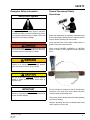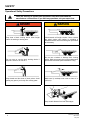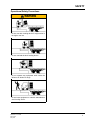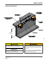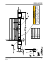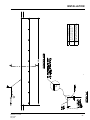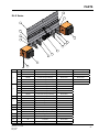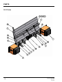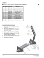
1
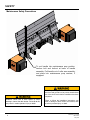
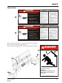
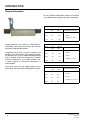
DL-NL-TS SERIES EOD Dock Leveler Owner’s/User’s Manual DLM • Division of Systems, Inc. • W194 N11481 McCormick Drive • Germantown, WI 53022 800.643.5424 • fax: 262.257.7399 • www.docksystemsinc.com • [email protected] Printed in U.S.A. Copyright © 2011 Manual No. 4111-0025 March 2011 May 2012 Table of Contents Page Safety Recognize Safety Information..................................................................1 General Operational Safety Precautions.................................................1 Operational Safety Precautions...............................................................2 Maintenance Safety Precautions.............................................................4 Safety Decals...........................................................................................5 Owner’s/User’s Responsibilities...............................................................6 Introduction General Information.................................................................................8 Dock Leveler Stock Specifications...........................................................8 Installation Installations Details..................................................................................9 Flush Mount-Weld On............................................................................ 10 Ramp Mount-Weld/Bolt On.................................................................... 12 Flush Mount-Bolt On.............................................................................. 14 Ramp Mount-Weld On w/Formed Angle................................................ 16 Formed Angle........................................................................................ 18 Ramp and Face Plate............................................................................ 20 Installation Check List............................................................................ 22 Operation Operating Instructions DL...................................................................... 23 Operating Instructions NL & TS............................................................. 24 Maintenance Periodic Maintenance............................................................................ 25 Troubleshooting Troubleshooting..................................................................................... 26 Parts DL-X Series............................................................................................ 27 NL-X Series............................................................................................ 28 TS Series............................................................................................... 30 Extension Spring Components.............................................................. 32 Torsion Spring Components................................................................... 34 Current vs. 2005 and Older.................................................................... 35 Handle Options...................................................................................... 36 Operating Link Options.......................................................................... 37 Bumper Components............................................................................. 38 Sliding Bumper Components................................................................. 39 Notes Customer Information............................................................................ 41 Warranty.................................................................................. Back Cover SAFETY Recognize Safety Information Safety-Alert Symbol The Safety-Alert Symbol identifies important safety messages on equipment, safety signs, in manuals, or elsewhere. When you see this symbol, be alert to the possibility of personal injury or death. Follow the instructions in the safety message. General Operational Safety Precautions Read and understand the operating instructions and become thoroughly familiar with the equipment and its controls before operating the dock leveler. Never operate a dock leveler while a safety device or guard is removed or disconnected. The use of the word CAUTION signifies possible hazard or unsafe practice which could result in personal injury. IMPORTANT The use of the word IMPORTANT is to draw attention to a procedure that needs to be followed to prevent machine damage. O p ng ati er Zo n e e The use of the word WARNING signifies the presence of a serious hazard or unsafe practice which may result in serious injury or death. Never remove DANGER, WARNING, or CAUTION signs or decals on the equipment unless replacing them. Zo n The use of the word DANGER signifies the presence of an extreme hazard or unsafe practice which will most likely result in severe injury or death. in at er p O g Do not activate the equipment until all unauthorized personnel in the area have been warned and have moved outside the operating zone. Remove any tools or foreign objects from the operating zone before starting. Keep the operating zone free of obstacles that could cause a person to trip or fall. Manual No. 4111-0025 March 2011 May 2012 1 SAFETY Operational Safety Precautions Learn the safe way to operate this equipment. Read and understand the manufacturer’s instructions. If you have any questions, ask your supervisor. Stay clear of dock leveling device when freight carrier is entering or leaving area. Chock/restrain all freight carriers. Never remove the wheel chocks until loading or unloading is finished and truck driver has been given permission to drive away. Do not move or use the dock leveling device if anyone is under or in front of it. Do not use a broken or damage dock leveling device. Make sure proper service and maintenance procedures have been performed before using. Keep hands and feet clear of pinch points. Avoid putting any part of your body near moving parts. Make sure lip overlaps onto trailer at least 4 in. (102 mm). Keep a safe distance from both side edges. 2 Manual No. 4111-0025 March 2011 May 2012 SAFETY Operational Safety Precautions Do not use dock leveling device if freight carrier is too high or too low. Do not overload the dock leveling device. Do not operate any equipment while under the influence of alcohol or drugs. Do not leave equipment or material unattended on dock leveling device. Manual No. 4111-0025 March 2011 May 2012 3 SAFETY Maintenance Safety Precautions To put handle into maintenance prop position, remove bolt and locknut at base of handle assembly. Pull handle out of roller arm assembly and place into maintenance prop receiver, if equipped. Post safety warnings and barricade the work area at dock level and ground level to prevent unauthorized use of the dock leveler before installation has been completed. ALWAYS stand clear of dock leveler lip when working in front of the dock leveler. Failure to do this may result in serious personal injury or death. 4 Failure to follow the installation instructions can result in damage to dock leveler, the facilities, and/ or serious personal injury or death. Manual No. 4111-0025 March 2011 May 2012 Unsupported dock leveler ramps can lower unexpectedly. 2 manual. sides of moving dock leveler. 2. Use of dock leveler restricted to 8. Never use damaged or trained operators malfunctioning dock leveler. Report 3. Always chock trailer wheels or problems immediately to supervisor. engage truck restraint before Before allowing vehicle to leave operating dock leveler or beginning to Maintenance/Service load or unload. 1. Read and follow all instructions, the dock always: 4. Never use hands or equipment to warnings and maintenance schedules move the ramp or lip in the owner’s/user’s manual. 5. Before activating dock leveler: 2. Maintenance/Service of dock leveler Ensure that no equipment, 9.12" Ensure trailer is backed in against restricted to trained personnel. material or people are on the 3. Place barriers on the driveway and on bumpers. dock floor to indicate service work is Remove any end loads if required. dock leveler. being performed. Check trailer alignment to avoid lip 4. DO NOT ENTER PIT unless dock interference. If lip does not lower to leveler is securely supported by trailer bed, reposition vehicle. Return the dock leveler to its maintenance prop. that truck bed supports OPERATION 7. Stay clear of and front and turn off and use stored position at dock level. 6. Ensure 5. Ifhinges electrically powered the leveler 1. Read extended and follow lip all or instructions andframe sides of moving dock leveler. OSHA lockout/tagout procedures. warnings in owner’s/user’s manual. 8. N e v e r u s e d a m a g e d o r instructions will result in death serious injury. 2. Use of dock Call 262.255.1510 for replacement placards, warning or owner’s/user’s manuals. leveler restricted to malfunctioning docklabels, leveler. Report Unsupported dockorleveler SAFETY Safety Decals SAFETY INFORMATION DANGER 3.25" Failure to follow posted 2 ramps can lower unexpectedly. trained operators problems immediately to supervisor. 3. Always chock trailer wheels or engage truck restraint before MAINTENANCE/SERVICE operating dock leveler or beginning to 1. Read and follow all instructions, load or unload. warnings and maintenance Supports the ramp before driving on 4. Never use hands Operation or equipment to schedules in the owner’s/user’s move ramp or lip follow all instructions and 1. Read and manual. ramp. 5. Before activating in dock of dock levelerand front and warnings theleveler: owner’s/user’s2. Maintenance/Service 7. Stay clear of hinges Ensure trailer is backed in against restricted to trained manual. sidespersonnel. of moving dock leveler. on the driveway and bumpers. 2. Use of dock leveler restricted 3. to Place barriers 8. Never use damaged or dock floor to indicate service work is Remove any end loads if required. trained operators malfunctioning dock leveler. Report being performed. Check trailer alignment to avoid lip 3. Always chock trailer wheels or4. DO NOT ENTER problems immediately to supervisor. PIT unless dock interference. If lip does not lower to engage truck restraint before leveler is securely supported by trailer bed, reposition vehicle. maintenance prop. operating dock leveler or beginning to Maintenance/Service 6. Ensure truck bed supports extended 9.12" turnfollow off andall useinstructions, load orframe unload. 1. powered Read and lip or leveler supports the ramp 5. If electrically procedures. 4. Never hands or equipment toOSHA lockout/tagout before drivinguse on ramp. warnings and maintenance schedules SAFETY INFORMATION DANGER Before allowing vehicle to leave the dock always: Ensure no equipment, Unsupported dock leveler or people are on rampsmaterial can lower unexpectedly. dock leveler. Before allowing Return dockvehicle leveler totoitsleave stored position at dock level. the dock always: 2 move the ramp or lip the owner’s/user’s manual. Call 262.255.1510 for replacement placards, warning labels, orinowner’s/user’s manuals. 5. Before activating dock leveler: 2. Maintenance/Service of dock leveler Ensure trailer is backed in against restricted to trained personnel. 3. Place barriers on the driveway and on bumpers. dock floor to indicate service work is Remove any end loads if required. OPERATION 7. Stay clear ofbeing and front and performed. Check trailer alignment to avoidsides lip of movinghinges 1. Read and follow all instructions and dock leveler. Control Box Size: 4. DO NOT ENTER PIT unless dock interference. If lip does not lower warnings in owner’s/user’s manual. 8. Ntoe v e r u s e d a m a g e d o r leveler is securely supported by Decalthe Size: 9.12leveler x 3.25 to its2. Use trailer of dock leveler restricted to malfunctioning dock leveler. Report bed, reposition vehicle. Return dock leveler Unsupported dock maintenance prop. trained operators problems immediately to supervisor. 6. Ensure that truck bed supports Filecan Name: 1751-0730 A ramps lower unexpectedly. stored position at dockRev level. 5. If electrically powered turn off and use 3. Always chock lip trailer wheels extended or the levelerorframe OSHA lockout/tagout procedures. engage truck restraint before MAINTENANCE/SERVICE dock262.255.1510 leveler or beginning to 1. Read and warning follow labels, all instructions, will resultallowing in deathvehicle or serious injury. operating Call for replacement placards, or owner’s/user’s manuals. Before to leave Failure to follow posted instructions will result in death or serious injury. Ensure that no equipment, material or people are on the dock leveler. SAFETY INFORMATION DANGER 3.25" Failure to follow posted instructions 2 the dock always: Ensure no equipment, material or people are on dock leveler. Return dock leveler to its stored position at dock level. Failure to follow posted instructions will result in death or serious injury. load or unload. 4. Never use hands or equipment to move ramp or lip 5. Before activating dock leveler: Ensure trailer is backed in against bumpers. Remove any end loads if required. Check trailer alignment to avoid lip interference. If lip does not lower to trailer bed, reposition vehicle. 6. Ensure truck bed supports extended lip or leveler frame supports the ramp before driving on ramp. 2. warnings and maintenance schedules in the owner’s/user’s manual. Maintenance/Service of dock leveler restricted to trained personnel. Place barriers on the driveway and dock floor to indicate service work is being performed. DO NOT ENTER PIT unless dock leveler is securely supported by maintenance prop. If electrically powered turn off and use OSHA lockout/tagout procedures. ! DANGER 3. 4. 5. Call 262.255.1510 for replacement placards, warning labels, or owner’s/user’s manuals. 1 Decal 2 will have two positions, one on the outside Control of theBox leftSize: bumper Size: 9.12and x 3.25 Decalone 2 willon have positions, oneright on the outside of theDecal left bumper and the two outside of the bumper. File Name: 1751-0730 Rev A one on the outside of the right bumper. Decal 3 represents the placement of the serial tag (left side of gusset) Decal 3 represents the placement of the serial tag (left side of gusset). ! DANGER 1 2 1 3 2 Ramp swings toward you. Stand Clear. Use maintenance strut while servicing. Failure to do so will result in death or serious injury. Ramp swings toward you. Stand Clear. Use maintenance strut while servicing. Failure to do so will result in death or serious injury. Refer to owner’s/user’s manual for proper procedure. Manual No. 4111-0025 March 2011 May 2012 Control Box Size: Decal Size: 4-5/16 x 4-1/4 File Name: 1751-0763 Rev A 5 OWNER’S/USER’S RESPONSIBILITIES 1. The owner/ user should recognize the inherent dangers of the interface between the loading dock and the transportation vehicle. The owner/ user should, therefore, train and instruct all operators in the safe operation and use of the loading dock equipment in accordance with manufacturer’s recommendations and industry standards. Effective operator training should also focus on the owner’s/user’s company policies and operating conditions. Maintaining, updating and re training all operators on safe working habits and operation of the equipment, regardless of previous experience, should be done on a regular basis and should include an understanding and familiarity with all functions of the equipment. Owner’s/ user’s shall actively maintain, update and retrain all operators on safe working habits and operations of the equipment. 2. The manufacturer shall provide to the initial purchaser all necessary information regarding Safety Information, Operation, Installation and Safety Precautions, Recommended Initial and Periodic Inspections Procedures, Planned Maintenance Schedule, Product Specifications, Troubleshooting Guide, Parts Break Down, Warranty Information, and Manufacturers Contact Information, as well as tables to identify the grade(slope) for all variations of length or configuration of the dock leveling device and information identifying the maximum uncontrolled drop encountered when sudden removal of support while in the working range of the equipment. 3. It is recommended that when the transportation vehicle is positioned correctly in the dock opening and in contact with both bumpers, there shall be a minimum of 4.00 inches (100mm) overlap of the leveling device and the transportation vehicle at all times during the loading and unloading process. 4. The Owner/User must review all name plates, placards, decals, instructions and posted warnings and place the same in view of the operator or maintenance personnel for whom such warnings are intended for. Contact manufacturer for any replacements. 5. Manufacturer’s recommended periodic maintenance and inspection procedures in effect at the date of shipment shall be followed at all times. Written documentation of maintenance, replacement parts or damage should be retained. In the event of damage notification to the manufacturer is required. 6. Loading dock equipment that has been structurally damaged or has experienced a sudden loss of main support while under load (such as what might occur when a transport vehicle pulls out from under the leveling device) shall be removed from service, inspected by a manufacturer’s authorized representative, and repaired or replaced as needed before being placed back in service. 7. Any modifications or alterations of loading dock equipment shall only be done with prior written approval from the manufacturer and the same shall be at least as safe as the original equipment was prior to the modification and shall also satisfy all safety requirements of the manufacturer for the particular application of the leveling device. 8. When industrial moving devices are being used in the loading or unloading of product from the transportation vehicle, this vehicle shall have the brakes and wheel chocks applied appropriately or all other positive restraining device shall be fully utilized. It is recommended that trailers with air-ride suspension systems shall have its air exhausted prior to performing loading and unloading operation to minimize trailer bed drop. 9. Loading dock safety equipment should never be used outside of its intended use, vertical working range, or capacity. Please consult the manufacturer if you have any questions as to the use, vertical working range or capacity of the equipment. Only properly trained and authorized personnel should operate the equipment. 10.When selecting loading dock safety equipment, it is important to consider not only present requirements but also future plans and any possible adverse conditions, environmental factors or usage. 6 Manual No. 4111-0025 March 2011 May 2012 NOTES This page intentionally left blank Manual No. 4111-0025 March 2011 May 2012 7 INTRODUCTION General Information DL-NL-TS Series Edge-of-Dock levelers are available in the following sizes, weight capacities, and options: Dimensions and Capacities Model # - Deck - Width Total Unit Width DL-6666” 104” 20,000 DL-7272” 110” 25,000 DL-7878” 116” Congratulations on your choice of a DLM Edge-ofDock leveler. This manual covers the DL-NL-TS series mechanical Edge-of-Dock levelers. Designed by DLM to be a marvel of simplicity and efficiency, your dock leveler, when properly installed, will provide many years of trouble-free performance with an absolute minimum of maintenance. To obtain maximum performance and longest possible use, a simple program of preventive maintenance is recommended. Once again, thank you and congratulations on your purchase of a DLM mechanical Edge-of-Dock leveler. Comparative Industry Rating 30,000 (N/A for DL-78) Dimensions and Capacities Model # - Deck - Width Total Unit Width Comparative Industry Rating NL-6666” 104” 20,000 NL-7272” 110” 25,000 30,000 35,000 NL-7878” 116” (N/A for NL-84) NL-8484” 122” Dimensions and Capacities Model # - Deck - Width Total Unit Width Comparative Industry Rating TS-66 66”104” 20,000 TS-72 72”110” 25,000 30,000 35,000 TS-78 78”116” (N/A for TS-78 & 84) TS-84 84”122” 8 Manual No. 4111-0025 March 2011 May 2012 INSTALLATION INSTALLATION DETAILS 50 INCH PREFERRED Only trained installation professionals with the proper equipment should install this product. IMPORTANT DO NOT remove the shipping bands around the dock leveler lip until instructed to do so. Manual No. 4111-0025 March 2011 May 2012 Post safety warnings and barricade the work area at dock level and ground level to prevent unauthorized use of the dock leveler before installation has been completed. Failure to follow the installation instructions can result in damage to dock leveler, the facilities, and/ or serious personal injury or death. 9 INSTALLATION E.O.D. Installation Instructions - Flush Mount - Weld On Follow all safety precautions prior to installation. A flush mount weld on application is used when an 8” wide (minimum) embed channel is securely anchored into the concrete at the dock edge, and the dock height is adequate. Installation Steps: 1. Remove all existing bumper material and protruding objects from dock edge. Clean and sweep dock edge free of debris and flammable chemicals before installing unit. 2. At chosen location for Edge-of-Dock leveler, locate the center of space and mark a point half of the base plate width to the left and right. 3. Using a proper lifting device, raise and position leveler on dock face with the top of the base plate being flush with the top of the embedded channel. Position ends of base plate to match up with marks made previously. 4. Tack weld base plate to dock steel on left hand end of the leveler. Check right hand end of base plate, ensure that end is against dock steel and that the top of the base plate is still flush with the top of the embedded channel. Tack right hand end to dock steel. 8. Installer must remove all welding slag, and repaint welded areas. 9. Installer must adjust springs on all mechanical Edge of Dock levelers to provide desired tension for smooth operation. Stand in front of leveler, with the unit raised and secured in the maintenance position, loosen jam nut on the underside of the linkage pin. To start allow about 3/4” to 1” of threads between top of jam nut and linkage pin. Using an open faced wrench, hold locknut on inside of spring while tightening threaded bolt until washer on top side of spring closes up tight to jam nut. Test operation of unit. Further adjust spring tension if needed by advancing jam nut toward linkage pin and tightening threaded rod. After desired unit operation is achieved, tighten jam nut to outer washer on spring. Springs must be adjusted alternately to have equal spring tension. 10. Before install is complete, installer must make a final operational check of dock leveler to verify all phases of install are correct. Installer must complete, sign and return the Installation Checklist upon completion. Reference page 22 5. Position bump blocks out approximately 5/8” from the edge of the inside flange of the bump block to the end of the base plate. This will allow for vertical welding of both the base plate and the bump block flange back to the dock steel. Top of the bump block cover plate should be flush with the top of the embed channel. Tack weld bump blocks to dock steel. 6. Check the positioning of the base plate and the bump blocks. 7. Complete welding of tacked parts as follows: A. Apply a continuous weld across top of each bumper and base plate to dock steel. Skip welding is acceptable to prevent warpage, but complete weld across the top must be completed. B. Weld vertically along each end of base plate and on both inboard and outboard flanges of bump blocks. C. Fully plug weld all holes in base plate. 10 Manual No. 4111-0025 March 2011 May 2012 Manual No. 4111-0025 March 2011 May 2012 DESCRIPTION Top of base plate and bumper cover plate to be flush with top of dock floor and embedded channel Apply continuous bevel weld across both bumpers and length of base plate. NOTE 1 2 Securely block or support ramp and lip when in vertical positions. Lack of proper bracing can result in ramp dropping during adjustment or installation causing personal injury or damage to unit. INSTALLATION 11 INSTALLATION E.O.D. Installation Instructions - RampMount - Weld/Bolt On Follow all safety precautions prior to installation. A ramp mount weld on application is used when adequate dock steel is securely anchored in the concrete at the dock edge, but the existing dock height is too low and the dock leveler must be installed above this height to correct this situation. Installation Steps: 1. Remove all existing bumper material and protruding objects from dock edge. Clean and sweep dock edge free of debris and flammable chemicals before installing unit. 2. At chosen location for Edge of Dock leveler, locate the center of space and mark a point half of the base plate width to the left and right. 3. At the points marked to each side of center, measure and mark points 7 - 3/4” below dock level less height the unit is to be raised to locate bottom of base plate. This will locate the top of the base plate X” above dock level. 4. Using a proper lifting device, raise and position the leveler base plate to marked position. While holding base plate tight against dock face, tack weld securely to dock steel on left hand end of leveler. Check right hand end of base plate, ensure that end is against dock steel and that the bottom of the base plate is even with the marks made previously. Tack right hand end to dock steel. Support unit until final welding is ready to complete. 5. Position bump blocks out approximately 5/8” out from the edge of the inside flange of the bump block to the end of the base plate. Position the top of the tread cover plate on the bump blocks to be flush with the top of the base plate. Tack weld bump blocks to dock steel. 6. Place steel ramp plate in position, flush with top backside of base plate. Mark along full length of back edge of ramp plate. Slide ramp plate forward over dock leveler the width of bushing tool, approximately 2”. 7. Place bushing tool on marked line at each end of ramp to ensure proper alignment at both ends, and tack weld ramp plate to dock leveler to hold ramp plate in place while bushing. A Skil Roto Hammer #736 or similar tool is recommended. 8. Using the back edge of the ramp plate as a guide, 12 groove concrete approximately 3/4” deep by 2” wide, and should be the entire length of ramp plate. 9. Break tack welds holding ramp in place, slide ramp plate back into position with the top of the ramp plate flush with the top of the base plate. Tack weld each end and center of ramp plate to base plate. 10. Drill 5/8” dia. by 5” deep holes through ramp plate at back edge. Install anchor bolts per manufacturers specifications, and tighten securely. Weld anchor bolt nuts to ramp plate using a 1/4” fillet weld all the way around the nut. Cut off any portion of the anchor bolt exposed through the nut, and plug weld around the top of the nut to the anchor bolt. Ensure the top of the nuts are well rounded for smooth rollover. 11. Complete welding of tacked parts as follows: A. Apply continuous weld across top of each bumper and base plate to ramp plate. Skip welding is acceptable to prevent warpage, but complete weld must be completed. B.Weld vertically along each end of base plate and on both inboard and outboard flanges of bump blocks. C Fully plug weld all holes in base plate. 12. Installer must remove all welding slag, and repaint welded areas. 13. Installer must adjust main springs on all mechanical Edge of Dock levelers to provide desired tension for smooth operation. Stand on ground in front of leveler, with the unit raised and secured in the maintenance position, loosen jam nut on the underside of the linkage pin. To start allow about 3/4” to 1” of threads between top of jam nut and linkage pin. Using an open faced wrench, hold locknut on inside of spring while tightening threaded bolt until washer on top side of spring closes up tight to jam nut. Test operation of unit. Further adjust spring tension if needed by advancing jam nut toward linkage pin and tightening threaded rod. After desired unit operation is achieved, tighten jam nut to outer washer on spring. Springs must be adjusted alternately to have equal spring tension. 14. Before install is complete, installer must make a final operational check of dock leveler to verify all phases of install are correct. Installer must complete, sign, and return the Installation Checklist upon completion. Reference page 22 Manual No. 4111-0025 March 2011 May 2012 Manual No. 4111-0025 March 2011 May 2012 DESCRIPTION Top of base plate and bumper cover plate to be flush with top of ramp plate. Apply continuous bevel weld across both bumpers and length of base plate. To figure ramp plate length, need 12” ramp for every 1-1/2” of rise to ramp. NOTE 1 2 3 Securely block or support ramp and lip when in vertical positions. Lack of proper bracing can result in ramp dropping during adjustment or installation causing personal injury or damage to unit. INSTALLATION 13 INSTALLATION E.O.D. Installation Instructions - Flush Mount - Bolt On Follow all safety precautions prior to installation. A flush mount bolt on application is used when there is no steel on dock edge, and the dock height is adequate. Additional steel ramp plate and bolting is required with this type of installation. Installation Steps: 1. Remove all existing bumper material and protruding objects from dock edge. Clean and sweep dock edge free of debris and flammable chemicals before installing unit. 2. At chosen location for Edge of Dock leveler, locate the center of space and mark a point half of the base plate width to the left and right. 3. At the points marked to each side of center, measure and mark points 7-1/2” below dock level (for 1/4” ramp plate) to locate position for bottom of base plate. This position will place the top of the base plate 1/4” above the dock floor. This position will vary with ramp plate thickness. 4. Mark line connecting these points and position support angles. Position angles as shown in installation drawing provided. Mark center of holes in each of the support angels. 5. At center marks, drill holes 5/8” dial. by 5” deep in concrete. Install anchor bolts with washers through support angles into holes in concrete. Tighten bolts until support angles are secure. Follow anchor manufacturers installation instructions for proper installation. 6. Using a proper lifting device, raise and position the leveler base plate to marked position, while resting on the support angles. While holding base plate tight against dock face, tack weld securely to support angles. 7. Drill 5/8” dia. by 5” deep holes in concrete through holes in base plate, and install anchor bolts with washers and tighten securely. 8. Position bump blocks out approximately 5/8” out from the edge of the inside flange of the bump block to the end of the base plate. Position the top of the tread cover plate on the bump blocks to be 1/4” above dock level. Note that this placement will vary with ramp plate thickness. Mark centers of holes in bump block flanges. 14 9. Drill 5/8” dia. by 5” deep holes at center marks. Reposition bump blocks, insert anchor bolts with washers and tighten securely to dock face. 10. Place steel ramp plate in position, flush with top backside of base plate. Mark along full length of base edge of ramp plate. Slide ramp plate forward over dock leveler the width of brushing tool, approximately 2”. 11. Place bushing tool on marked line at each end of ramp to ensure proper alignment at both ends, and tack weld ramp plate to dock leveler to hold ramp plate in place while bushing. A Skil Roto Hammer #736 or similar tool is recommended. 12. Using the back edge of the ramp plate as a guide, groove concrete approximately 5/8” deep by 2” wide, and should be the entire length of ramp plate. 13. Break tack welds holding ramp in place, slide ramp plate back into position with the top of the ramp plate flush with the top of the base plate. Tack weld each end and center of ramp plate to base plate. 14. Drill 5/8” dia. by 5” deep holes through ramp plate at back edge. Install anchor bolts per manufacturers specifications, and tighten securely. Weld anchor bolt nuts to ramp plate using a 1/4” fillet weld all the way around the nut. Cut off any portion of the anchor bolt exposed through the nut, and plug weld around the top of the nut to the anchor bolt. Ensure the top of the nuts are well rounded for smooth rollover. 15. Complete welding of tacked parts as follows: A.Apply continuous weld across top of each bumper and base plate to ramp plate. Skip welding is acceptable to prevent warpage, but complete weld must be completed. B.Weld bottom of base plate support angles using a 1/4” fillet weld. 16. Installer must remove all welding slag, and repaint welded ares. 17. Installer must adjust main springs on all mechanical edge of dock levelers to provide desired tension for smooth operation. Stand on ground in front Manual No. 4111-0025 March 2011 May 2012 INSTALLATION of lever, with the unit raised and secured in the maintenance position, loosen jam nut on the underside of the linkage pin. To start allow about 3/4” to 1” of threads between top of jam nut and linkage pin. Using an open faced wrench, hold locknut on inside of spring while tightening threaded bolt until washer on top side of spring closes up tight to ram nut. Test operation of unit. Further adjust spring tension if needed by advancing jam nut toward linkage pin and tightening threaded rod. After desired operation is achieved, tighten jam nut to outer washer on spring. Springs must be adjusted alternately to have equal spring tension. 18. Before install is complete, installer must make a final operation check of dock leveler to verify all phases of install are correct. Installer must complete, sign and return the Installation Checklist up on completion. reference page 22 Manual No. 4111-0025 March 2011 May 2012 Securely block or support ramp and lip when in vertical positions. Lack of proper bracing can result in ramp dropping during adjustment or installation causing personal injury or damage to unit. NOTE DESCRIPTION 1 Top of base plate and bumper cover plate to be flush with top of ramp plate. 2 Apply continuous bevel weld across both bumpers and length of base plate. 15 INSTALLATION E.O.D. Installation Instructions - Ramp Mount - Weld On w/Formed Angle Follow all safety precautions prior to installation. A ramp mount-weld on used with a formed angle application is used when dock edge is damaged, there is no dock steel securely anchored into the concrete, and the dock height is too low and leveler must be installed above this height to correct this situation. Installation Steps: 1. Remove all existing bumper material and protruding objects from dock edge. Clean and sweep dock edge free of debris and flammable chemicals before installing unit. 2. Review and follow formed angle installation instructions prior to leveler installation. Page 18 3. At chosen location for Edge of Dock leveler, locate the center of space and mark a point half of the base plate width to the left and right. 4. At the points marked to each side of center, measure and mark points 7-3/4” below dock level less height the unit is to be raised to locate bottom of base plate. This will locate the top of the base plate X” above dock level. 5. Using a proper lifting device, raise and position the leveler base plate to marked position. While holding base plate tight against dock face, tack weld securely to dock steel on left hand end of leveler. Check right hand end of base plate, ensure that end is against dock steel and that the bottom of the base plate is even with the marks made previously. Tack right hand end to dock steel. Support unit until final welding is ready to complete. 6. Position bump blocks out approximately 5/8” out from the edge of the inside flange of the bump block to the end of the base plate. Position the top of the tread cover plate on the bump blocks to be flush with the top of the base plate. Tack weld bump blocks to dock steel. 7. Place steel ramp plate in position, flush with top backside of base plate. Mark along full length of back edge of ramp plate. Slide ramp plate forward over dock leveler the width of bushing tool, approximately, 2”. 8. Place bushing tool on marked line at each end of ramp to ensure proper alignment at both ends, and tack weld ramp plate to dock leveler to hold ramp plate in place while bushing. A Skil Roto Hammer #736 or similar tool is recommended. 16 9. Using the back edge of the ramp plate as a guide, groove concrete approximately 3/4” deep by 2” wide, and should be the entire length of ramp plate. 10. Break tack welds holding ramp in place, slide ramp plate back into position with the top of the ramp plate flush with the top of the base plate. Tack weld each end and center of ramp plate to base plate. 11. Drill 5/8” dia. by 5” deep holes through ramp plate at back edge. Install anchor bolts per manufacturers specifications, and tighten securely. Weld anchor bolt nuts to ramp plate using a 1/4” fillet weld all the way around the nut. Cut off any portion of the anchor bolt exposed through the nut, and plug weld around the top of the nut to the anchor bolt. Ensure the top of the nuts are well rounded for smooth rollover. 12. Complete welding of tacked parts as follows: A. Apply continuous weld across top of each bumper and base plate to ramp plate. Skip welding is acceptable to prevent warpage, but complete weld must be completed. B Weld vertically along each end of base plate and on both inboard and outboard flanges of bump blocks. C Fully plug weld all holes in base plate. 13. Installer must remove all welding slag, and repaint welded areas. 14. Installer must adjust main springs on all mechanical Edge of Dock levelers to provide desired tension for smooth operation. Stand on ground in front of leveler, with the unit raised and secured in the maintenance position, loosen jam nut on the underside of the linkage pin. To start allow about 3/4” to 1” of threads between top of jam nut and linkage pin. Using an open faced wrench, hold locknut on inside of spring while tightening threaded bolt until washer on top side sprint closes up tight to jam nut. Test operation of unit. Further adjust spring tension if needed by advancing jam nut toward linkage pin and tightening threaded rod. After desired unit operation is achieved, tighten jam nut to outer washer on spring. Springs must be adjusted alternately to have equal spring tension. 15. Before install is complete, installer must make a final operational check of dock leveler to verify all phases of install are correct. Installer must complete, sign, and return the Installation Checklist upon completion. reference page 22. Manual No. 4111-0025 March 2011 May 2012 Manual No. 4111-0025 March 2011 May 2012 DESCRIPTION Top of base plate and bumper cover plate to be flush with top of ramp plate. Apply continuous bevel weld across both bumpers and length of base plate. To figure ramp plate length, need 12” ramp for every 1-1/2” of rise to ramp. To install formed angle, see formed angle installation instructions. NOTE 1 2 3 4 Securely block or support ramp and lip when in vertical positions. Lack of proper bracing can result in ramp dropping during adjustment or installation causing personal injury or damage to unit. INSTALLATION 17 INSTALLATION E.O.D. Installation Instructions - Formed Angle Follow all safety precautions prior to installation. A formed angle is used when there is no existing dock steel and concrete at the dock edge has been damaged. The formed angle is required to rebuild the damaged concrete edge for a proper installation if the dock height is adequate. Installation Steps: 1. Remove all existing bumper material and protruding objects from dock edge. Clean and sweep dock edge free of debris and flammable chemicals before installing unit. 2. At chosen location for the formed angle, locate the center of space and mark a point half of the angle width to the left and right. 3. Using a proper lifting device, raise and position the formed angle to marked position, slide formed angle against dock face. 4. Mark along full length of back edge of formed angle. Slide angle forward the width of brushing tool, approximately 2”. 5. Place bushing tool on marked line at each end of formed angle to ensure proper alignment at both ends. A Skil Roto Hammer #736 or similar tool is recommended. 6. Using the back edge of the formed angle as a guide, groove concrete approximately 5/8” deep by 2” wide, and should be the entire length of the formed angle. 7. Slide formed angle back until tight against dock face. drill 5/8” dia. by 5” deep holes through formed angle at back edge. Install anchor bolts per manufacturers specifications, and tighten securely. Weld anchor bolt nuts to formed angle using a 1/4” fillet weld all the way around the nut. Cut off any portion of the anchor bolt exposed through the nut, and plug weld around the top of the nut to the anchor bolt. Ensure the top of the nuts are well rounded for smooth rollover. 8. Drill 5/8” dia. by 5” deep holes in dock face through holes in formed angle. Install anchor bolts with washers and tighten securely per manufacturers specifications. 18 Manual No. 4111-0025 March 2011 May 2012 Manual No. 4111-0025 March 2011 May 2012 1 NOTE Secure formed angle with (18) anchor bolts, (9) each side DESCRIPTION INSTALLATION 19 INSTALLATION E.O.D. Installation Instructions - Ramp and Face Plate Follow all safety precautions prior to installation. A ramp mount requiring a face plate application is used when there is no existing dock steel and the concrete at the dock edge has been damaged. The dock height can be low, high, or adequate for this application, however, the face plate and ramp plate are required to rebuild the damaged concrete edge. Installation Steps: 1. Remove all existing bumper material and protruding objects from dock edge. Clean and sweep dock edge free of debris and flammable chemicals before installing unit. 2. At chosen location for the face plate, locate the center of space and mark a point half of the face plate width to the left and right. 5/8” dia. by 5” deep holes through ramp plate at back edge. Install anchor bolts per manufacturers specifications, and tighten securely. Weld anchor bolt nuts to ramp plate using a 1/4” fillet weld all the way around the nut. Cut off any portion of the anchor bolt exposed through he nut, and plug weld around the top of the nut to the anchor bolt. Ensure the top of the nuts are well rounded for smooth rollover. 11. Apply a continuous fillet weld at the created joint between the face plate and ramp. Skip welding should be the proper method used to avoid warpage, and a complete weld must be achieved. 3. Using a proper lifting device, raise and position the face plate to marked position, and push face plate against dock face. 4. Top of face plate should be flush with the top of dock floor. mark center of holes in face plate into dock face. Drill 5/8” dia. by 5” holes into dock face. Install anchor bolts with washers per manufacturers specifications and tighten securely. 5. Place ramp plate to match each end of the face plate. Leading (forward) edge of ramp plate should be flush with dock face. 6. Mark along full length of back edge of ramp plate. Slide ramp forward the width of bushing tool, approximately 2”. 7. Place bushing tool on marked line at each end of ramp to ensure proper alignment at both ends. A Skil Roto Hammer #736 or similar tool is recommended. 8. Tack weld ramp to face plate on each end to secure in place. 9. Using the back edge of the ramp plate as a guide, groove concrete approximately 5/8” deep by 2” wide, and should be the entire length of the lamp plate. 10. Break tack welds and slide ramp back until forward edge is flush with dock face. Tack weld ramp on each end and center to face plate. Drill 20 Manual No. 4111-0025 March 2011 May 2012 Manual No. 4111-0025 March 2011 May 2012 Secure formed angle with (18) anchor bolts, (9) each side Apply continuous fillet weld across entire length of face plate and ramp 2 DESCRIPTION 1 NOTE INSTALLATION 21 INSTALLATION - CHECK LIST E.O.D. Installation Checklist Date: __________ Order No.: __________ Serial Number:______________ Installer: ____________________________ Customer Name: _____________________ Address: ____________________________ City/State: ___________________________ Zip: __________ Phone: _________________ 1. Unit is properly aligned and installed properly. 2. All welding has been fully completed. 3. Welding slag has been removed. 4. Welds and other affected areas have been painted. 5. Springs have been properly adjusted. 6. Unit is functioning properly without fault. I hereby certify that all installation and/or repair work has been inspected and approved by: Company: ________________________ Date Completed: _________________ Name: ___________________________ Signature: ______________________ A copy of this document must be signed and faxed to Systems, Inc at 262-257-7399 to the attention Customer Service/ Technical Service. To be placed in job folder. Copy as needed 22 Manual No. 4111-0025 March 2011 May 2012 OPERATION OPERATING INSTRUCTIONS FOR DL-SERIES 1. With leveler in stored position, back the truck into position against the bump blocks. 2. Truck should be chocked before operation of leveler. 3. While standing behind the unit, use lifting hook to pull back and up on rivet OR engage on the notch until leveler is cocked. 4. Then actuate the leveler by placing the lifting hook into lip plate notch and manually lifting the hook until the lip plate section extends over the truck bed. Lower lip to bed of the trailer. 5. When truck departs leveler automatically returns to stored position. RIVET NOTCH Only trained personnel should operate the dock leveler. DO NOT use a broken or damaged dock leveler. Make sure proper service and maintenance procedures have been performed on leveler before using. Truck/trailer wheels must be chocked unless the truck restraint is used. Never remove the wheel chocks until loading/unloading is finished and truck driver has been given permission to leave. Stay clear of dock leveler when freight carrier is entering or leaving dock area. Make sure platform lip rests on the truck/trailer bed with at least 4 in. (102 mm) of overlap. DO NOT move or use the dock leveler if anyone is under or in front of leveler. Maintain a safe distance from side edges of leveler during the loading/unloading process. Keep hands and feet clear of pinch points. Avoid putting any part of your body near moving parts. Failure to follow these instructions may result in serious personal injury or death. Failure to follow these instructions may result in severe personal injury or death. Manual No. 4111-0025 March 2011 May 2012 23 OPERATION OPERATING INSTRUCTIONS FOR NL & TS SERIES 1. Grasp the captured operating handle and raise to its full extended length. 3. Push forward on operating handle against the rivet, rotating leveler out onto truck. 2. Move handle toward you, rotating center plate back past vertical. Lip plate extend link arm will engage at this time. 4. Return handle to stored position. 5. To remove leveler from truck repeat step number one until the lip clears the bed of the trailer. Return leveler and handle to the stored position. OR When the truck departs, the unit will automatically return to the stored position. RIVET 24 Manual No. 4111-0025 March 2011 May 2012 MAINTENANCE PERIODIC MAINTENANCE When maintenance is to be performed in front of the dock leveler, support the lip with the handle in the maintenance prop position OR by other means. Always post safety warnings and barricade the work area at dock level and ground level to prevent unauthorized use of the dock leveler before maintenance is complete. Failure to do this may result in serious personal injury or death. Put handle into maintenance prop position by removing bolt and locknut at base of handle assembly. Pull handle out of roller arm assembly and place into maintenance prop receiver. If maintenance requires that the lip be in the extended position, raise the lip by hand and support the lip with the lip maintenance prop. Always stand clear of the dock leveler lip when working in front of the dock leveler. Failure to do this may result in serious personal injury or death. Securely block or support ramp and lip when in vertical position. Lack of proper bracing can result in ramp dropping during maintenance causing personal injury or damage to unit. Quarterly Maintenance Regular maintenance must be performed on a weekly and quarterly schedule. • Follow weekly maintenance schedule in addition to the following: Weekly Maintenance • Lubricate the following areas with light-weight machine oil: • Operate the dock leveler through the complete operating cycle to maintain lubrication. • Look for cracks or damage. Repair or replace damaged or cracked parts as needed. • Inspect the platform hinge and the lip hinge areas. The hinge areas must be kept free of dirt and debris. Build-up of foreign material in the hinge areas will increase wear and cause abnormal operation. reference page 9. Extend link arm pivots Lip linkage pivot Operating link pivots Torsion arm pivots • Lubricate the following areas with white lithium grease: Lip plate grease fittings Base plate grease fittings Note: Failure to lubricate the dock leveler will cause abnormal operation of the leveler. Manual No. 4111-0025 March 2011 May 2012 25 TROUBLESHOOTING Symptom Unit does not operate properly Extended link arm does not latch out lip or unlatch Possible Cause Debris impacted on or around the leveler Clean out debris on or around leveler Insufficient lubrication Lubricate leveler Excessive weight on top of deck Remove weight from deck. Main springs need more tension or less tension Adjust main spring tension as needed Damaged or missing parts Repair of replace as needed Debris impacted in extended Clean out debris from extended link arm link arm Extended link arm needs lubrication 26 Solution Lubricated extended link arm Manual No. 4111-0025 March 2011 May 2012 PARTS 5 DL-X Series 6 1 5 2 9 6 10 4 11 7 3 S 4 Y S T E M S, P O W E R A D I N C. L o a d i n g D o c k E q u i p m e n DL-X MODEL - BILL OF MATERIAL DRAWN BY 9 SR TOLERANCES (UNLESS OTHERWISE NOTED) FRACTIONAL: `1/32" DECIMAL: 8 CHECKED BY 1 SIZE/CAPACITY DESCRIPTION PART NUMBER (15”) LIP PART NUMBER (17”LIP) 1 6620/25 Lip Plate & Hinge Assembly DOTH-3112 DOTH-3142 1 6630 Lip Plate & Hinge Assembly DOTH-3114 DOTH-3116 1 7220/25 Lip Plate & Hinge Assembly DOTH-3130 DOTH-3154 1 7230 Lip Plate & Hinge Assembly DOTH-3126 DOTH-3128 1 7820/25 Lip Plate & Hinge Assembly DOTH-3939 DOTH-3971 1 6620/25 Center Plate & Hinge Assembly DOTH-3200 6630 Center Plate & Hinge Assembly DOTH-3243 1 7220/25 Center Plate & Hinge Assembly DOTH-3210 1 7230 Center Plate & Hinge Assembly DOTH-3245 1 7820/25 Center Plate & Hinge Assembly DOTH-3942 1 ALL Base Plate & Hinge Assembly Consult Factory 2 All 66 Hinge Pin DOTH-3104 2 All 72 Hinge Pin DOTH-3122 2 All78 Hinge Pin DOTH-3946 5 2 All Rivet - Button DOTH-2400 6 2 All Rivet - Flat DOTH-2398 1 6620/25/30, 7220/25 Spring Linkage Assy - X-Regular DOTH-3618 1 7230, 7820/25 Spring Linkage Assy - X-Hvy Duty DOTH-3630 DOTH-3342 2 3 4 7 This print is the property of Systems, Inc. and represents a proprietary article in which Systems, Inc. re patent and other rights, including exclusive rights of use and/or manufacture and/or sale. Possession o not convey any permission to reproduce, print or manufacture the article or articles shown therein, suc granted only by written authorization signed by an officer or other authorized agent of Systems,Inc. the QTY 1 8 1 All Lifting Hook 9 2 All Extra Hvy Duty Bumper Blocks DBBS-3500 10 2 All X-Gusset DOTH-3589 11 - All Secondary Gussets DOTH-3319 Manual No. 4111-0025 March 2011 May 2012 5/9/2 DL-X-1 .00 = `.01" .000 = `.005" ANGULAR: `1~ ITEM DATE DRAWING NO. 27 PARTS NL-X Series 28 Manual No. 4111-0025 March 2011 May 2012 PARTS ITEM 1 2 3 4 QTY SIZE/CAPACITY DESCRIPTION PART NUMBER (15”) LIP PART NUMBER (17”LIP) 1 6620/25 Lip Plate & Hinge Assembly DOTH-4047 DOTH-4048 1 6630 Lip Plate & Hinge Assembly DOTH-4049 DOTH-4050 1 6635 Lip Plate & Hinge Assembly DOTH-4051 DOTH-4052 1 7220/25 Lip Plate & Hinge Assembly DOTH-4053 DOTH-4054 1 7230 Lip Plate & Hinge Assembly DOTH-4055 DOTH-4056 1 7235 Lip Plate & Hinge Assembly DOTH-4057 DOTH-3167 1 7820/25 Lip Plate & Hinge Assembly DOTH-4058 DOTH-4059 1 7830 Lip Plate & Hinge Assembly DOTH-3924 DOTH-4060 1 8420/25 Lip Plate & Hinge Assembly DOTH-3156 DOTH-3155 DOTH-4061 1 8430 Lip Plate & Hinge Assembly DOTH-3159 1 6620/25 Center Plate & Hinge Assembly DOTH-4062 1 6630 Center Plate & Hinge Assembly DOTH-4063 1 6635 Center Plate & Hinge Assembly DOTH-4064 1 7220/25 Center Plate & Hinge Assembly DOTH-4065 1 7230 Center Plate & Hinge Assembly DOTH-4066 1 7235 Center Plate & Hinge Assembly DOTH-3258 1 7820/25 Center Plate & Hinge Assembly DOTH-4067 1 7830 Center Plate & Hinge Assembly DOTH-3923 1 8420/25 Center Plate & Hinge Assembly DOTH-3242 1 8430 Center Plate & Hinge Assembly DOTH-3241 1 ALL Base Plate & Hinge Assembly Consult Factory 2 6620/25/30 Hinge Pin DOTH-3104 2 6635 Hinge Pin DOTH-4312 2 7220/25/30 Hinge Pin DOTH-3122 2 7235 Hinge Pin DOTH-4313 2 7820/25/30 Hinge Pin DOTH-3946 2 8420/25/30 Hinge Pin DOTH-3920 5 2 All Rivet - Button DOTH-2400 6 2 All Rivet - Flat DOTH-2398 7 2 All Extra Hvy Duty Bumper Blocks DBBS-3500 1 6620/25/30, 7220/25 Spring Linkage Assy - X-Regular DOTH-3618 8 1 6635,7230,7820/25, 8420/25 Spring Linkage Assy - X-Hvy Duty DOTH-3630 1 7235, 7830/35, 8430 Spring Linkage Assy - 3 Spring DOTH-3626 9 2 All X-Gusset DOTH-3589 10 11 - All Secondary Gussets DOTH-3319 1 66/7220-30 NL Roller Arm Assembly - Open DOTH-3834 1 78/84 NLIII Operating Link Assembly DOTH-3696 1 35K Only NLIII Operating Link Assembly DOTH-3697 1 66/7220-30 NL Pipe Handle Assembly DOTH-3833 1 66/7235 - 78/84 NLIII Hanlde Assembly DOTH-3694 13 1 All Extend Link Arm DOTH-3585 14 1 All Extend Link Arm Stop DOTH-3586 15 2 All Pivot Block DOTH-3316 16 1 All Shoulder Bolt DOTH-2061 17 1 All Locknut DOTH-2136 12 18 1 All Lip Stop DOTH-3734 19 1 All NLIII Handle Holder DOTH-3695 Manual No. 4111-0025 March 2011 May 2012 29 PARTS TS Series 6 16 15 14 12 2 11 4 1 5 9 13 8 3 4 18 19 20 S Y S L o a d i n 17 NL-RR MO DRAWN BY 21 SR TOLERANCES 10 (UNLESS OTHERWISE NOTED) FRACTIONAL: `1/32" DECIMAL: .00 = `.01" .000 = `.005" 7 30 ANGULAR: `1~ This print is the property of Systems, I patent and other rights, including exclu not convey any permission to reprodu granted only by written authorization s Manual No. 4111-0025 March 2011 May 2012 PARTS ITEM QTY SIZE/CAPACITY DESCRIPTION PART NUMBER (15”) LIP PART NUMBER (17”LIP) 1 6620/25 Lip Plate & Hinge Assembly DOTH-4068 DOTH-4069 1 6630 Lip Plate & Hinge Assembly DOTH-4070 DOTH-4071 1 6635 Lip Plate & Hinge Assembly DOTH-4072 DOTH-4073 1 7220/25 Lip Plate & Hinge Assembly DOTH-4074 DOTH-4075 1 7230 Lip Plate & Hinge Assembly DOTH-4076 DOTH-4077 1 7235 Lip Plate & Hinge Assembly DOTH-4078 DOTH-4079 1 7820/25 Lip Plate & Hinge Assembly DOTH-4080 DOTH-4081 1 7830 Lip Plate & Hinge Assembly DOTH-4082 DOTH-4083 1 8420/25 Lip Plate & Hinge Assembly DOTH-4084 DOTH-4085 1 8430 Lip Plate & Hinge Assembly DOTH-4086 DOTH-4087 1 6620/25 Center Plate & Hinge Assembly DOTH-4088 1 6630 Center Plate & Hinge Assembly DOTH-4089 1 6635 Center Plate & Hinge Assembly DOTH-4090 1 7220/25 Center Plate & Hinge Assembly DOTH-4091 1 7230 Center Plate & Hinge Assembly DOTH-4092 1 7235 Center Plate & Hinge Assembly DOTH-4093 1 7820/25 Center Plate & Hinge Assembly DOTH-4094 1 7830 Center Plate & Hinge Assembly DOTH-4095 1 8420/25 Center Plate & Hinge Assembly DOTH-4096 1 8430 Center Plate & Hinge Assembly DOTH-4097 1 ALL Base Plate & Hinge Assembly Consult Factory 2 6620/25/30 Hinge Pin DOTH-3104 2 6635 Hinge Pin DOTH-4312 2 7220/25/30 Hinge Pin DOTH-3122 2 7235 Hinge Pin DOTH-4313 2 7820/25/30 Hinge Pin DOTH-3946 2 8420/25/30 Hinge Pin DOTH-3920 5 2 All Rivet - Button DOTH-2400 6 2 All Rivet - Flat DOTH-2398 1 2 3 4 7 All Extra Hvy Duty Bumper Blocks DBBS-3500 8 2 All HL LInkage Adder Assembly DOTH-3675 9 2 All X-Gusset DOTH-3589 1 66/7220-30 NLI Operating Link Assembly DOTH-3726 1 78/84 NLIII Operating Link Assembly DOTH-3696 1 35K Only NLIII Operating Link Assembly DOTH-3697 10 1 66/7220-30 NLI Handle Assembly (Tube) DOTH-3752 11 1 Optional NLI Handle Assembly (Solid) DOTH-3769 1 78/84 NLIII Handle Assembly DOTH-3694 12 1 All Extend Link Arm DOTH-3585 13 1 All Extend Link Arm Stop DOTH-3586 14 2 All Pivot Block DOTH-3316 15 1 All Shoulder Bolt DOTH-2061 16 1 All Locknut DOTH-2136 DOTH-3734 17 1 All Lip Stop 18 1 All Pivot Block DOTH-3597 19 2 All Cotter Pin DOTH_2375 20 1 All Spring DOTH-2559 21 1 All NLIII Handle Holder DOTH-3695 Manual No. 4111-0025 March 2011 May 2012 31 PARTS DOTH-3618 Replacement Extension Spring Kits (Includes all parts listed below) Item Quantity Part Number 1 2 3 4 5 6 7 8 9 10 1 2 4 2 1 2 2 4 2 2 Description DOTH-3620 Bar - Lip linkage DOTH-2061 1-1/2” Shoulder Bolt DOTH-2131 Nylon Lock Nut DOTH-3621 Bar - Base Linkage DOTH-2347 Pin - Linkage DOTH-2390 Roll Pin DOTH-2520 Spring, Extension, Reg., Painted DOTH-2209 Washer - Fender - Zinc Plated DOTH-2045 HHCS - Grade 5 - Zinc Plated DOTH-2130 Hex Nut - Zinc Plated - Grade 5 Extension Spring Adjustment Instructions 1. Lift and secure leveler in full upright maintenance position to start. 2. Loosen jam nut A by turning the nut clockwise. Once jam nut is loosened, use an open faced wrench to hold the locknut B inside the spring body. Tighten the hex bolt C by turning clockwise. 3. To start, the top fender washer should be tightened until the washer is about one and a half inches from the underside of the linkage pin. 4. Tighten the jam but A by turning the nut clockwise until the jam nut is tight against the top fender washer. 5. Test leveler operation. If spring tension is not sufficient, repeat the previous steps until desired tension is achieved. 6. Return leveler to stored position. 32 Manual No. 4111-0025 March 2011 May 2012 PARTS DOTH-3630 Replacement Extension Spring Kits (Includes all parts listed below) Item Quantity Part Number 1 2 3 4 5 6 7 8 9 10 1 2 4 2 1 2 2 4 2 2 Description DOTH-3620 Bar - Lip linkage DOTH-2061 1-1/2” Shoulder Bolt DOTH-2131 Nylon Lock Nut DOTH-3621 Bar - Base Linkage DOTH-2347 Pin - Linkage DOTH-2390 Roll Pin DOTH-2521 Spring, Extension, Reg., Painted DOTH-2209 Washer - Fender - Zinc Plated DOTH-2045 HHCS - Grade 5 - Zinc Plated DOTH-2130 Hex Nut - Zinc Plated - Grade 5 Extension Spring Adjustment Instructions 1. Lift and secure leveler in full upright maintenance position to start. 2. Loosen jam nut A by turning the nut clockwise. Once jam nut is loosened, use an open faced wrench to hold the locknut B inside the spring body. Tighten the hex bolt C by turning clockwise. 3. To start, the top fender washer should be tightened until the washer is about one and a half inches from the underside of the linkage pin. 4. Tighten the jam but A by turning the nut clockwise until the jam nut is tight against the top fender washer. 5. Test leveler operation. If spring tension is not sufficient, repeat the previous steps until desired tension is achieved. 6. Return leveler to stored position. Manual No. 4111-0025 March 2011 May 2012 33 PARTS DOTH-3675 Torsion Spring Kit (Includes all parts listed below) Item Quantity Part Number 1 2 3 4 5 6 7 8 9 10 11 12 1 1 1 1 1 1 3 1 1 2 2 2 Description DOTH-3305 L&R Gusset Assembly w/Bearing DOTH-3327 HL Model Gusset w/Guide DOTH-3679 HL Torsion Tube Assembly DOTH-3676 HL Torsion Bar Assembly DOTH-2509 Spring Torsion DOTH-3316 Bar-Pivot DOTH-2033 HHCS - Grade 2 - Zinc Plated DOTH-2121 Nylon Lock Nut DOTH-3682 HL Plate Locking Torsion DOTH-3617 Bar - 6630 L-Linkage DOTH-2061 1-1/2” Shoulder Bolt DOTH-2136 Center Locknut Torsion Spring Adjustment Instructions 1. Lift and secure leveler in full upright maintenance position to start. 2. Remove nut (A) from hex bolt (B) 3. Place crescent wrench on torsion tube assembly, apply enough downward force to tube assembly until hex bolt can be removed. 4. Continue to apply downward force until flange on tube assembly has the next hole in series come into alignment with hex bolt hole. 5. Insert hex bolt (B) through the flange on the tube assembly, and tighten nut until secure. 6. Test leveler operation. If spring tension is not sufficient, repeat the previous steps until desired tension is achieved. 7. Return leveler to stored position. 34 Manual No. 4111-0025 March 2011 May 2012 PARTS CURRENT VS 2005 and Older Item Quantity Part Number 1 1 DOTH-3730 2 1 DOTH-3744 3 1 DOTH-3585 4 1 DOTH-3586 Manual No. 4111-0025 March 2011 May 2012 Description Bar - NL Extended Link Arm (pre 09/2005) NL SB Catch Assembly (pre 09/2005) Bar - NL Extend Link Arm (09/2005 - present) NL SB Catch Assembly (09/2005 - present) 35 PARTS HANDLE OPTIONS Item Quantity Part Number 1 2 3 4 36 1 1 1 1 Description DOTH-3752 NL Handle Assembly (Tube) DOTH-3769 NL Handle Assembly (Solid) DOTH-3691 NLII Handle Assembly (Formed) DOTH-3694 NLIII Handle Assembly Manual No. 4111-0025 March 2011 May 2012 PARTS OPERATING LINK OPTIONS Item Quantity Part Number 1 2 1 1 DOTH-3726 DOTH-3696 3 1 DOTH-3697 4 1 DOTH-2449 Description NL Operating Link Assembly NLIII Operating Link Assembly Operating Link Assembly for all 35K units (not shown) Roller Bearing ITEM QTY PART NO. 1 1 DOTH-3726 NL OPERA 2 1 DOTH-3696 NLIII OPER 3 1 DOTH-3834 NLIII ROLL PIPE 4 2 1 Manual No. 4111-0025 March 2011 May 2012 37 Item Quantity Part Number 1 1 4 4 4 4 2 DOTH-3537 12” BB Weldment DOTH-3505 Rubber - Tuf-Cord DOTH-2056 Hex Head Cap Screw DOTH-2210 Wahser - Flat - Zinc Plated DOTH-2208 Washer - Flat DOTH-2129 Nylon Lock Nut DBBS-3506 15” Projection x 18” high (option) 1 4 6 5 4 3 2 1 IT EM 1 Q TY 1 2 3 4 5 6 Description P D AR O D T T 4 D OT H-3 NO 4 O H D T -3 53 . 4 D OT H-2 50 7 1 O H 0 5 2 D O TH -22 56 RU " B TH -2 10 H B B -2 208 W EX BE WE B 12 D IL R 9 W AS HE - LDM ES L O H A T A N YL SH ER D C UF EN CR F M O ER - F A -C T IPT AT N P O IO E LO - F LAT SC RD N RI AL C LAT R K E ZI W N N U C T PL AT ED DBBS-3500 Complete 15” Projection Bumper Assembly DKIT-3540 Bumper & All Hardware (weldment not included) 4 7/ X 1 1 1/ 6- 2 X SI 1/ 2" D 14 13 ZE 2 7/ " D IA UN 16 C I A -1 X 4 3U 1/ N 4 C PARTS 3 4 3 2 4 1 2 5 1 5 6 6 38 Manual No. 4111-0025 March 2011 May 2012 QT Y PA 1 DO RT N 2 O T DO H-35 . 2 37 TH -35 DO 12" 1 BIL 1 T LO DO H-35 4 AN BB W 15 TH EL DESC F M GL D -35 E BA RIP ATE ME -1 17 R RIA TIO 12" - BB 2" BB NT L N SL SL S L I IDI NG DING IDE S BB PL TOP AT EW /RU BB ER PARTS DBBS-3512 Complete 15” Projection Sliding Bumper Assembly Item Quantity Part Number 1 2 2 1 DOTH-3537 DOTH-3514 DOTH-3515 DOTH-3517 12” BB Weldment Angle - 12” BB Slide Bar - BB Sliding Stop 12” Sliding BB Plate w/Rubber 4 3 2 1 IT E M 1 2 3 4 Description 2 4 4 2 1 1 3 3 Manual No. 4111-0025 March 2011 May 2012 39 MISCELLANEOUS This page intentionally left blank 40 Manual No. 4111-0025 March 2011 May 2012 MISCELLANEOUS Customer Information A NOTE: The model/serial number decal (A) is located on the outboard side of the outer most (LH) gusset or base plate. When you receive your DL, NL or TS series Edgeof-Dock leveler, write down the dock leveler model and serial number in the form provided. This will help ensure safe keeping of the numbers in the event the model/serial number decal (A) becomes lost or damaged. Also, write down DLM’s job number, the company that installed the dock leveler, and the original owner’s name. This will all help to identify the specific dock leveler if more information is required. When ordering, use part numbers and description to help identify the item ordered. Do not use “item” numbers. These are only for locating the position of the parts. Always give dock leveler MODEL NUMBER and/or SERIAL NUMBER. For service, call or contact: Systems, Inc. P.O. Box 309 Germantown, WI 53022 Dock Leveler Information Model Serial No. DLM, Job No. Original Owner Information Name Address Installer Information Name Address Date of Installation Phone:(800) 643-5424 Fax: (262) 255-5917 Manual No. 4111-0025 March 2011 May 2012 41 STANDARD PRODUCT WARRANTY SYSTEMS, INC. warrants that its products will be free from defects in design, materials and workmanship for a period of one (1) year from the date of shipment. All claims for breach of this warranty must be made within 30 days after the defect is or can with reasonable care, be detected. In no event shall any claim be made more than 30 days after this warranty has expired. In order to be entitled to the benefits of this warranty, the product must have been properly installed, maintained and operated in accordance with all manufacturer’s recommendations and/or specified design parameters and not otherwise have been subject to abuse, misuse, misapplication, acts of nature, overloading, unauthorized repair or modification, application in a corrosive environment or lack of maintenance. Periodic lubrication, adjustment and inspection in accordance with all manufacturers’ recommendations are the sole responsibility of the Owner/User. In the event of a defect, as determined by SYSTEMS INC., covered by this warranty, SYSTEMS INC. shall remedy such defect by repairing or replacing any defective equipment or parts, bearing the cost for the parts, labor and transportation. This shall be exclusive remedy for all claims whether based on contract, negligence or strict liability. WARRANTY LIMITATIONS THE ABOVE WARRANTIES ARE IN LIEU OF ANY OTHER WARRANTIES, WHETHER EXPRESSED OR IMPLIED, INCLUDING BUT NOT LIMITED TO ANY IMPLIED WARRANTY OF MERCHANTABILITY OR FITNESS FOR A PARTICULAR PURPOSE. SYSTEMS INC. AND ITS SUBSIDIARIES SHALL NOT IN ANY EVENT BE LIABLE TO ANYONE, INCLUDING THIRD PARTIES, FOR INCIDENTAL, CONSEQUENTIAL OR SPECIAL DAMAGES OF ANY KIND INCLUDING BUT NOT LIMITED TO, BREACH OF WARRANTY, LOSS OF USE, LOSS OF PROFIT, INTERRUPTION OF BUSINESS OR LOSS OF GOODWILL.