1
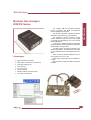
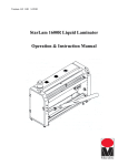
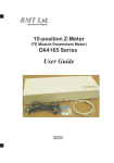
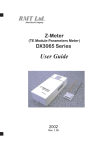
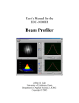
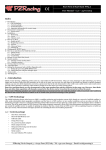
2
Components for Gas Analysis
RMT Ltd.
Gas Analyzers 2 .2
Gas Analyzers
Contents
Modular Gas Analyzer DX6100 Series . . . . . . . . . . . . . . . . . . . . . . . . . . . . . . . . . . . . . . .23
Advantages . . . . . . . . . . . . . . . . . . . . . . . . . . . . . . . . . . . . . . . . . . . . . . . . . . . . . . . . . . .23
Design Features . . . . . . . . . . . . . . . . . . . . . . . . . . . . . . . . . . . . . . . . . . . . . . . . . . . . . . . . .24
Principles of Operation . . . . . . . . . . . . . . . . . . . . . . . . . . . . . . . . . . . . . . . . . . . . . . . . . . .24
Operation Overview . . . . . . . . . . . . . . . . . . . . . . . . . . . . . . . . . . . . . . . . . . . . . . . . . . . . . .25
Noise level . . . . . . . . . . . . . . . . . . . . . . . . . . . . . . . . . . . . . . . . . . . . . . . . . . . . . . . . . . . . .25
Inside the Analyzer . . . . . . . . . . . . . . . . . . . . . . . . . . . . . . . . . . . . . . . . . . . . . . . . . . . . . .26
Output Connectors . . . . . . . . . . . . . . . . . . . . . . . . . . . . . . . . . . . . . . . . . . . . . . . . . . . . .26
Functional Diagram . . . . . . . . . . . . . . . . . . . . . . . . . . . . . . . . . . . . . . . . . . . . . . . . . . . . .26
DX6102 Optocomponent Mating Module . . . . . . . . . . . . . . . . . . . . . . . . . . . . . . . . . . . .27
DX6106 Optical Unit . . . . . . . . . . . . . . . . . . . . . . . . . . . . . . . . . . . . . . . . . . . . . . . . . . . .27
DX6101 Controller Module . . . . . . . . . . . . . . . . . . . . . . . . . . . . . . . . . . . . . . . . . . . . . . .27
Working with DX6100 Analyzer . . . . . . . . . . . . . . . . . . . . . . . . . . . . . . . . . . . . . . . . . . . . .28
DX6100 Vision II Software . . . . . . . . . . . . . . . . . . . . . . . . . . . . . . . . . . . . . . . . . . . . . . .28
System Requirements . . . . . . . . . . . . . . . . . . . . . . . . . . . . . . . . . . . . . . . . . . . . . . . . . . .28
Zero Adjustment . . . . . . . . . . . . . . . . . . . . . . . . . . . . . . . . . . . . . . . . . . . . . . . . . . . . . . .29
Calibration . . . . . . . . . . . . . . . . . . . . . . . . . . . . . . . . . . . . . . . . . . . . . . . . . . . . . . . . . . . .29
Parameters of Analyzer Adjustment . . . . . . . . . . . . . . . . . . . . . . . . . . . . . . . . . . . . . . . .29
Housing and Dimensions . . . . . . . . . . . . . . . . . . . . . . . . . . . . . . . . . . . . . . . . . . . . . . . . .30
Specifications . . . . . . . . . . . . . . . . . . . . . . . . . . . . . . . . . . . . . . . . . . . . . . . . . . . . . . . . . . .31
Common . . . . . . . . . . . . . . . . . . . . . . . . . . . . . . . . . . . . . . . . . . . . . . . . . . . . . . . . . . . . .31
Carbon Dioxide (CO2) . . . . . . . . . . . . . . . . . . . . . . . . . . . . . . . . . . . . . . . . . . . . . . . . . . .31
Hydrocarbons (CnHm) . . . . . . . . . . . . . . . . . . . . . . . . . . . . . . . . . . . . . . . . . . . . . . . . . . .32
Methane (CH4) selective . . . . . . . . . . . . . . . . . . . . . . . . . . . . . . . . . . . . . . . . . . . . . . . . .32
Standard Kits . . . . . . . . . . . . . . . . . . . . . . . . . . . . . . . . . . . . . . . . . . . . . . . . . . . . . . . . . . .32
DX6100 . . . . . . . . . . . . . . . . . . . . . . . . . . . . . . . . . . . . . . . . . . . . . . . . . . . . . . . . . . . . . .32
DX6100 OEM . . . . . . . . . . . . . . . . . . . . . . . . . . . . . . . . . . . . . . . . . . . . . . . . . . . . . . . . .32
DX6100 Series
Components for Gas Analysis
Gas Analyzers
Modular Gas Analyzer
DX6100 Series
The company RMT Ltd introduces DX6100
series of Modular and OEM non-dispersive
infrared (NDIR) Gas Analyzers.
Advantages
u
u
u
u
u
u
u
u
High selectivity and stability
Wide range of measured concentrations
Small gas sampling cell
Fast response
The principle of operation is based on selective
absorption of IR radiation by gas molecules.
The differential double frequency optical
scheme provides a high accuracy in wide ranges
of humidity and temperature due to the internal
thermostabilization.
A new type of middle infrared (IR) integrated
Optopair (Detector and Light Emitters) with built-in
thermoelectric cooling is used.
The light sources are pulsed solid state middle-IR Light Emitters. The Photodetector is based
on the Lead Selenide (or Lead Sulphide) photoresistor.
There are several models suitable for the following gases: CO2, CH4, CnHm.
Other optional gas analyzers are available on
request.
Both complete modular and OEM versions are
available.
Long service life
No moving parts
Miniature design and small weight
Low power consumption
RMT Ltd.
53 Leninskij prosp. Moscow 119991 Russia u phone: 7-095-132-6817 u fax: 7-095-132-5870 u e-mail: [email protected] u http://www.rmtltd.ru
23
DX6100 Series
Components for Gas Analysis
Principles of Operation
Gas Analyzers
The Non-Dispersive Infra-Red Spectroscopy (NDIR)
measurement method is implemented in the DX6100
Analyzer.
The analyzer provides gases concentration measurement based on the classical double channel optical
scheme.
One of the beams (measuring channel) has the
wavelength tuned to the optical absorption line of the
measured gas. The other beam (reference channel)
has the wavelength that is out of the adsorption band of
the measured gas.
After passing through the gas sampling cell the two
light beams intensities are compared.
actual measurements conditions: total transparency of
gas volume, optics imperfection and so on.
The reference channel is used for indirect measuring of the initial light intensity and allows to eliminate
The principle of gas concentration measurement realized in
the DX6100 analyzer
Design Features
The DX6100 Gas Analyzer is specially designed for
fast response, high sensitivity, low noise and low power
consumption.
A number of design features contribute to the performance :
u The infrared sources are special narrow-band
pulsed Light Emitters operating in a microsecond range. The light sources have long life
(more than 10,000 hours).
u Radiation from Light Emitters passes through
gas sampling cell, reflects from the mirrors and
is focused onto wide-band Photodetector.
u Light Emitters and Photodetector chips are integrated into a single housing and placed
onto a miniature TE cooler for thermostabilization.
u Microcontroller provides temperature
regulation with better then 0.1°C accuracy. The temperature is software selectable from the ambient value down to
–20°C.
u Heat dissipated from the warm side of
TE coolers results in few degrees of
overheating of gas sampling cell above
the ambient. This factor plays the role of
vapor anti-condensation at high moisture
operation.
u All driving function of Light Emitters and
24
u
u
u
Detector are operated by the on-board microcontroller.
Pre-amplified outputs are maintained by the
microcontroller. The final result is digital data of
measured gas concentration and is available in
realtime through the RS-232C or an analog port.
For the signal processing the calibrated data of
Optical Unit is used. The data is stored in Optical
Unit’s EEPROM.
The RS-232C port is also used for the remote
control from a computer.
RMT Ltd.
53 Leninskij prosp. Moscow 119991 Russia u phone: 7-095-132-6817 u fax: 7-095-132-5870 u e-mail: [email protected] u http://www.rmtltd.ru
DX6100 Series
Components for Gas Analysis
Operation Overview
The order of measurements with the DX6100 device
is as follows:
1. The individual calibration of device is required
using standard gas mixtures.
The Detector output signal is non-linear with respect
to the measured gas concentration. The intensity of
light that passed through the gas sampling cell is the
integral of various optical rays from Light Emitter. The
sensitivity of Detector and performance of Light Emitter
depend very much on their operating temperatures.
The Detector output signals (both measuring and
reference channels) are measured while calibration
gases with known concentration are passing through
the gas sampling cell. The data obtained are used for
polynomial extrapolation of calibration results.
The polynomial coefficients and the “zero” ratio are
stored into the device internal on-board EEPROM
memory.
The first calibration is made by the manufacturer.
The factory standard calibration uses not fewer than
five standard gas mixtures.
Several calibrations are made at different ambient
temperatures (in the specified operating range) and at
corresponding optimal operating temperatures of the
integrated Detector-Emitter pair.
It is possible to store up to 15 such calibrations for
further application.
Noise level
Default values are extracted by the device microcontroller from the memory and correspond to the
ambient conditions at calibration procedure.
It is also possible to use the value of measured
ambient temperature provided by the on-board digital
thermosensor.
3. To preserve high accuracy of the device it is necessary to make “zero” adjustments periodically as recommended in the DX6100 User’s Guide.
4. Periodicity of the device recalibration is 1 year. It
can be done at the Manufacturer’s factory or by a user
with the help of the corresponding DX6100 Vision II
software.
390
Time constant=1.0 s
CO2 Concentration, ppm
The main parameter of the digital filter is Time constant. It is
adjustable in the range 0.1…60 s.
The values of ambient temperature and pressure
can be inputted by a user manually into the device
memory at the beginning of the experiment.
Time constant=0.1 s
CO2 Concentration, ppm
Adjustable noise level is realized
due to application of digital filtration
algorithm.
370
350
330
310
1
31
61
91
121
390
370
350
330
310
151
1
31
370
350
330
310
61
91
Time, s
RMT Ltd.
91
121
151
121
151
Time constant=5.0 s
CO2 Concentration, ppm
CO2 Concentration, ppm
Time constant=0.2 s
390
31
61
Time, s
Time, s
1
Gas Analyzers
2. During a routine operation the detector output
signals are measured. Using a known “zero” value and
polynomial coefficients the gas concentration is calculated with a high accuracy as a function of measuring
and reference channels signals ratio.
Resulted concentration is calculated in absolute
mmol/m3 units.
The device provides (if required) recalculation of the
concentration into relative ppm units. But to convert
absolute units (mmol/m3) into relative (ppm) ones it is
necessary to know ambient temperature and pressure.
390
370
350
330
310
1
31
61
91
121
151
Time, s
53 Leninskij prosp. Moscow 119991 Russia u phone: 7-095-132-6817 u fax: 7-095-132-5870 u e-mail: [email protected] u http://www.rmtltd.ru
25
DX6100 Series
Components for Gas Analysis
Inside the Analyzer
Gas Analyzers
The DX6100 Analyzer consists of three main
parts:
u DX6106 Optical Unit
u 6101 Controller Module
u 6102 Optocomponent Mating Module
Those parts combined together and housed into a
body form a complete version of the DX6100
Analyzer.
The same components taken separately, supplemented by a set of special cables, form a Kit for OEM
applications (DX6100 OEM) analyzer.
DX6101
Optical Unit
Gas sampling
tube
DX6102
Module
DX6101 Module
DX6100 Analyzer, the cover removed
Output Connectors
There are the following units on the front panel of
the DX6100 Analyzer:
u Power supply input connector
u RS-232 connector
u Analog output connector
u Two-color LED indicator
u Inlet and outlet gas ports
Output Connectors
Supply
input
Two-color
LED
RS232
Port
Analog
output
Gas outlet Gas inlet
port
port
Functional Diagram
The DX6102 Optopair Mating Module is connected
with DX6101 Controller Module by special cable via
miniature 20 pin System Interface connectors.
Digital Thermometer is an optional module for the
measurement of the absolute value of ambient temperature with 0.5°C accuracy.
Functional Diagram of the DX6100 Gas Analyzer
26
RMT Ltd.
53 Leninskij prosp. Moscow 119991 Russia u phone: 7-095-132-6817 u fax: 7-095-132-5870 u e-mail: [email protected] u http://www.rmtltd.ru
Inside the Analyzer
Components for Gas Analysis
DX6101 Controller Module
The 6010 Controller Module provides the following
functions:
u Amplification and processing of Detector’s output signals
u
u
u
u
Driving by the gas analyzer through the RS-232
port
Light and sound alarm.
Gas Analyzers
u
u
Storage of identifier and individual calibration
parameters
Thermostabilization of Optopair using built-in
PID driving algorithm of built-in TE cooler with
thermosensor signals forming for Light Emitters
driving
Filtering and digitizing of Detector pre-amplified
output
Conversion of amplified output signals into gas
concentration value using the stored calibration
data
6101 Controller Module
DX6106 Optical Unit
The DX6106 Optical Unit is the head part of the Gas
Analyzer. It consists of an isolated gas sampling cell
(the spherical mirror and the sapphire window are
placed at the end sides) and a new generation integrated optopair with the DX6102 electronic mating module.
The internal volume of the gas cell depends on the
Optical Unit version. The gas sampling cell has two gas
inlets with 5.0 mm internal diameter.
The gas sampling cell can be easily disassembled
for the service of the internal optics (mirror and window). For this purpose both the top and bottom covers
can be removed and the optical components extracted.
The mirror has a special SiO2 safety layer.
The DX6106 Optical Units are manufactured in two
versions: with DX6106.C2 and DX6106.C4 gas sampling cells (See Table).
Depending on what gas and what limiting concentration value must be measured, it is furnished with one or
the other sampling cells.
Optical Unit
Gas sampling Number of Total path Internal volume,
cell
passes length, mm
ml
DX6106.C2
2
25
1
DX6106.C4
4
85
10
DX6106.C2 Sampling Cell
DX6106.C4 Sampling Cell
DX6102 Optocomponent Mating Module
The DX6102 Optocomponent Mating Module
provides:
u Pre-amplification of photodetector’s signals
u Light Emitters driving
u
Power supply of Photodetector and
Thermistors with precise voltage supply
DX6102 Mating Module
RMT Ltd.
53 Leninskij prosp. Moscow 119991 Russia u phone: 7-095-132-6817 u fax: 7-095-132-5870 u e-mail: [email protected] u http://www.rmtltd.ru
27
Dx6100 Series
Components for Gas Analysis
Working with DX6100 Analyzer
Gas Analyzers
In general nothing is required for the Analyzer operation except the external power source.
But for many purposes, such as the change of tunings of the analyzer, zero adjustment, calibration and
so on, the control computer is necessary.
A user can control the Analyzer with computer in two
ways:
1) The remote control by the Analyzer is available
using the RS-232 port by a set of microcontroller commands.
The commands can be divided into two groups:
driving commands and setting commands.
All commands have the same format – the symbol
string, which consists of the command name identifier
and a list of its parameters. Some commands have no
parameters. The commands are described in User’s
Guide.
This way is very useful if a user is going to integrate
the DX6100 analyzer into a more complicated system.
2) The second way is based on using the DX6100
Vision II software.
DX6100 Vision II Software
The DX6100 Vision II software provides all possible
operational modes of the DX6100 Gas Analyzer. The software has a simple interface and does not demand a
User's special knowledge.
The software is delivered with the DX6100 Gas
Analyzer.
Also it is available for free dawnload from RMT website:
www.rmtltd.ru
Setup Window
System Requirements
To run the DX6100 Vision II software
the following system requirements must
be met or exceeded:
u Intel Pentium class computer with
Windows 95/98/2000 operating
system
u Free COM port
u 16 MB of RAM (32 MB recommended)
u 6 MB free hard drive space
u CD ROM drive
u Mouse or compatible pointing
device
Main Window
28
RMT Ltd.
53 Leninskij prosp. Moscow 119991 Russia u phone: 7-095-132-6817 u fax: 7-095-132-5870 u e-mail: [email protected] u http://www.rmtltd.ru
DX6100 Series
Components for Gas Analysis
The DX6100 Vision II program allows an adjustment
of various operation parameters of the device. The following parameters are among them:
u Parameters of Light Emitters and Photodetector
operation (pulse duration, Emitter current,
Detector gain, synchronization and others)
u Telemetry structure (output parameters, repeating rate, duration of measurements and others)
u Warning levels
u Analog output adjustment and others
But before editing a parameter study the device
description thoroughly, please. Many of available
parameters should be adjusted very carefully by experienced users only or along the manufacturer’s recommendation.
Gas Analyzers
Parameters of Analyzer Adjustment
Setting Window
Calibration
One of the very useful utility of the DX6100 Vision II
software is Calibration subroutine.
The program allows users to carry out quite a complex procedure of the device calibration.
The first calibration in a specified concentration
range is made by the manufacturer.
A user can perform any recalibration with the use of
the program.
According to the instructions the procedure consists
of several steps that must be completed by a user.
First of all, a user need to have a set of standard
gases with concentrations in specified range. Then a
user is to start the Calibration program and follow
instructions step-by-step.
The advisable periodicity of the device recalibration
is 1 (one) year. It could be done at the factory of the
manufacturer or by a User with the help of DX6100
Vision software.
Zero Adjustment
To ensure high accuracy, a simple adjustment can
be made during operation to adjust the “zero” ratio.
The procedure requires to start the sensor in the
Calibration mode and to flow up any "zero" gas through
the gas sampling cell.
The new “zero” coefficient will be stored in EEPROM
in place of the old value after the adjustment procedure
is complete.
RMT Ltd.
Calibration Procedure
53 Leninskij prosp. Moscow 119991 Russia u phone: 7-095-132-6817 u fax: 7-095-132-5870 u e-mail: [email protected] u http://www.rmtltd.ru
29
DX6100 Series
Components for Gas Analysis
Housing and Dimensions
Gas Analyzers
The enclosure of the Analyzer is
made of a painted aluminum alloy.
The extruded body of the enclosure is closed by covers from end
faces.
The rubber gaskets placed
between the body and covers provide
the enclosure with water resistance.
DX6100 Analyzer Outline Dimensions (in millimeters)
DX6106.C2 Optical Unit Outline Dimensions
(in millimeters)
30
DX6106.C4 Optical Unit Outline Dimensions
(in millimeters)
RMT Ltd.
53 Leninskij prosp. Moscow 119991 Russia u phone: 7-095-132-6817 u fax: 7-095-132-5870 u e-mail: [email protected] u http://www.rmtltd.ru
DX6100 Series
Components for Gas Analysis
Specifications
Common
Type
NDIR Gas Analyzer
Lead Selenide with TE cooler
Gas Analyzers
Detector
Measured Gases (available options)
CO2
CnHm
CH4
Carbon Dioxide
Hydrocarbons
Methane
Timing
Output Repeating Rate
Average Time Constant
0.01…20 Hz
0.1…60 sec
Alarms
Light
Sound
Two-color LED
>85 dB
Voltage
Current
+6 to +15 VDC
300 mA (max)
Digital
Analog
RS-232C
0…4095 mV
Supply Requirements
Interface
Operation Conditions
Moisture Protection
Temperature Range
Relative Humidity
IP65 (excluding OEM version)
-10 to +50 oC
5 to 100%
Mechanical (Modular Option)
Dimensions
Weight
60x80x122 mm
310 g
DX6101 Controller Module
DX6102 Mating Plate
DX6106.20 Sampling Cell
DX6106.40 Sampling Cell
Mounting Base
80x43x14 mm
47x26x8 mm
34x32x27 mm
40x36.5x27 mm
135x48x3.5 mm
DX6101 Controller Module
DX6102 Mating Plate
DX6106.20 Sampling Cell
DX6106.40 Sampling Cell
Mounting Base
24 g (max)
8 g (max)
50 g (max)
55 g (max)
20 g (max)
Mechanical (OEM Option)
Dimensions
Weight
Carbon Dioxide (CO2)
Concentration Range 1)
Noise Level 2,3)
Accuracy 3)
Zero Drift 3)
0…1000 ppm
< 3 ppm
10 ppm
0…5 %vol
< 0.15 %
0.50%
0.02%
0…20 %vol
< 0.15 %
0.50%
Information furnished by RMT Ltd is believed to be reliable. However, no responsibility is assumed for possible inaccuracies or
omission. Specifications are subject to change without notice.
RMT Ltd.
53 Leninskij prosp. Moscow 119991 Russia u phone: 7-095-132-6817 u fax: 7-095-132-5870 u e-mail: [email protected] u http://www.rmtltd.ru
31
Specifications
Components for Gas Analysis
Specifications (...continued)
Hydrocarbons (CnHm)
Gas Analyzers
Concentration Range 1)
Noise Level 2,3)
Accuracy 3)
Zero Drift 3)
0…1000 ppm
< 3 ppm
10 ppm
0…5 %vol
< 0.10 %
0.50%
0.02%
0…100 %vol
< 0.15 %
0.50%
0…1000 ppm
< 25 ppm
100 ppm
0…5 %vol
< 0.3 %
1.0%
0.02%
0…100 %vol
< 0.5 %
1.0%
Methane (CH4) selective
Concentration Range 1)
Noise Level 2,3)
Accuracy 3)
Zero Drift 3)
Notes:
1) Optional concentration ranges are available on request.
2) At Averaging Time Constant= 0.2 s.
3) If value in %, then it means relative units.
4) Software adjustable.
Standard Kits
DX6100
#
Item
Code
Q-ty, pcs
1
Gas Analyzer
DX6100
1
2
Power supply cable
DX6100-C-02
1
3
RS-232 cable
DX6100-C-03
1
4
Analog interface cable
DX6100-C-04
1
5
AC/DC adaptor
1
6
DX6100 User Manual
1
7
DX6100 Vision software CD
1
DX6100 OEM
#
Item
Q-ty, pcs
Optical Unit
DX6106.xx
2
Controller module
DX6101-x.xx
1
3
Optopair mating module
DX6102-x.xx
1
4
Module interconnect cable
DX6100-C-11
1
5
Power supply cable
DX6100-C-12
1
6
RS-232 cable
DX6100-C-13
1
7
Analog interface cable
DX6100-C-14
1
8
AC/DC adaptor
1
9
DX6100 User Manual
1
10 DX6100 Vision software CD
32
Code
1
1
1
RMT Ltd.
53 Leninskij prosp. Moscow 119991 Russia u phone: 7-095-132-6817 u fax: 7-095-132-5870 u e-mail: [email protected] u http://www.rmtltd.ru
Components for Gas Analysis
Gas Analyzers
Notes
RMT Ltd.
53 Leninskij prosp. Moscow 119991 Russia u phone: 7-095-132-6817 u fax: 7-095-132-5870 u e-mail: [email protected] u http://www.rmtltd.ru
33
Gas Analyzers
Components for Gas Analysis
RMT Ltd.
53 Leninskij prosp. Moscow 119991 Russia u phone: 7-095-132-6817 u fax: 7-095-132-5870 u e-mail: [email protected] u http://www.rmtltd.ru