1
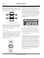
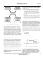
DRAFTING MANUAL
Update 58
Update
By:
R.L.58Homkes*
1.0 GENERAL
Standard(s) or publication(s):
Software is now an integral part of the design, development,
and manufacturing of our products. It is also an integral part of
many of the products themselves since embedded controllers
are used in an increasing number of applications. Because of
the importance of software, it must be treated as another form
of engineering, not as an add-on to the electromechanical area.
This means that the standard development and documentation
processes that are used for hardware must also be used for
software.
The adherence to certain common development standards
documents that the software is being developed in a consistent
and predictable manner. Initial impetus for using a certain
standard may come from the desire to receive certification (e.g.
ISO-9000) or to meet bid specifications for a particular
contract (e.g., a DOD contract). A more important reason for
standards, including documentation standards, is to provide a
common basis of understanding and communication between
the developers and the acquirers of software. This understanding should result in quicker agreements on specifications,
fewer change orders, and the production of better quality
software.
A standard process of development and documentation will
also help the software development organization itself. When
dealing with embedded controllers, concurrent engineering can
only occur if the mechanical, electrical, computer and manufacturing engineering areas are involved from the beginning of
the product development process. Systems engineering must
properly partition the product functionality among mechanical,
electrical, and computer components. This partitioning must be
documented so that the development team knows the boundary
of each specialty. This, in turn, helps during product testing
when determining whether a certain problem is hardware or
software related.
Thus all software, whether it is of the embedded controller;
information systems; or command, control, and communications type, must be documented.
2.0 REFERENCES
2.1 Government
Defense Automated Printing Services
Building 4 / Section D
700 Robbins Avenue
Philadelphia, PA 19111-5094
215-697-2000
http://www.dodssp.daps.mil/
* Purdue University
Kokomo, Indiana
Section K19
Page 1
December 1997
Software Documentation
MIL-STD-100G, Engineering Drawing Practices (supersedes
DOD-STD-100, will probably be superseded by ASME
Y14.100)
MIL-STD-473, Configuration Management (supersedes
MIL-STD-483, will probably be superseded by MILSTD-2549)
MIL-STD-498, Software Development and Documentation
(will probably be superseded by ISO/IEC IS 12207)
2.2 Industry
Electronic Industries Association
2500 Wilson Blvd.
Arlington, VA 22201
703-907-7500
http://www.eia.org/
Standard(s) or publication(s):
CMB4-1A, Configuration Management Definitions for
Digital Computer Programs
CMB4-2, Configuration Identification for Digital Computer
Programs
CMB4-4, Configuration Change Control for Digital Computer Programs
Institute of Electrical and Electronics Engineers
IEEE Service Center
445 Hoes Lane
Piscataway, NJ 08855-1331
800-678-4333
http://standards.ieee.org/index.html
Standard(s) or publication(s):
IEEE Std 610.12, Glossary of Software Engineering Terminology
IEEE Std 828, Standard for Software Configuration Management Plans
IEEE Std 829, Standard for Software Test Documentation
IEEE Std 1042, Guide for Software Configuration Management
IEEE Std 1063, Standard for User Documentation
IEEE Std 1074, Standard for Developing Software Life
Cycle Processes
GENIUM PUBLISHING
*Supersedesissue
issueofofDecember,
July 1985 1982
*Supersedes
Section K19
Page 2
December 1997*
DRAFTING MANUAL
Software Documentation
Update 58
2.3 Standards Organizations
ance standards — Part 4: Guide to dependability
program management
American National Standards Institute
11 West 42nd Street
New York, NY 10036
212-642-4900 (voice) 212-398-0023 (fax)
http://www.ansi.org/
ISO 9001:1994, Quality system model for quality assurance
in design, development, production, installation and
servicing.
ISO 9002:1994, Quality system model for quality assurance
in production, installation and servicing.
Standard(s) or publication(s):
ANSI/ANS 10.3-1995, Documentation of Computer Software
ANSI/IEEE 1002-1987 (R1993), Software Engineering
Standards, Standard Taxonomy
ANSI/IEEE 1063-1989, Software User Documentation
ANSI/IEEE 610.12-1990, Standard Glossary of Software
Engineering Terminology
ANSI/IEEE 829-1983 (R1991), Software Test Documentation
ANSI/ISO/ASQC Q9000-3-1991, Quality Management and
Quality Assurance Standards -Guidelines for the
Application of ANSI/ISO/ASQC 9001 to the Development, Supply and Maintenance of Software
Software Engineering Institute
Carnegie Mellon University
Pittsburgh, PA 15213
412-268-5800
http://www.sei.cmu.edu/
Standard(s) or publication(s):
Software Capability Maturity Model, Version 1.1
Systems Capability Maturity Model
International Organization of Standards
Case Postale 56
CH-1211
Geneva Switzerland
http://www.iso.ch
ISO 9003:1993, Quality system model for quality assurance
in final inspection and test.
2.4 Other Organizations
American Society for Quality
611 East Wisconsin Avenue
Milwaukee, WI 53202-4606
800-248-1946 or 414-272-8575
http://www.asqc.org/
3.0 DEFINITIONS
3.1
Algorithm — The ordered set of steps required to
complete a task.
3.2
Alpha testing — The first testing of software, usually
by software developers, to verify that it is working as
designed. Done in a simulated or lab environment. See
verification.
3.3
Applications software — Software that processes data
for a user. Contrast with systems software.
3.4
Assembler — A program that translates an assembly
language program into machine code. Contrast with
compiler.
3.5
Baseline — A fixed point in time in the product
development process that results from a formal event
such as a code review. The baseline is represented by an
engineering document or set of documents, which are
approved, released, and placed under change control as a
result of the event.
3.6
Beta testing — The testing of software, usually by a test
user group, that validates the software actually meets
customer requirements. See validation.
3.7
CAD — Computer Aided Design. The use of computers
to design products.
3.8
CAM — Computer Aided Manufacturing. The use of
computers to control the manufacturing of products.
3.9
CIM — Computer Integrated Manufacturing. The
Standard(s) or publication(s):
ISO 9000-1: 1994, Quality management and quality assurance standards-Part 1: Guidelines for selection and use.
ISO 9000-2:1993, Quality management and quality assurance standards-Part 2: Generic guidelines for the
application of ISO 9001, ISO 9002 and ISO 9003.
ISO 9000-3:1991, Quality management and quality assurance standards-Part 3: Guidelines for the application of
ISO 9001 to the development, supply and maintenance
of software.
ISO 9000-4:1993, Quality management and quality assur*Supersedes
*Supersedes issue
issue of
of December,
July 1985 1982
GENIUM PUBLISHING
DRAFTING MANUAL
Section K19
Page 3
December 1997
Software Documentation
Update 58
integration of computers, electrical, and mechanical
devices in the design and manufacturing of products.
This may also include automated accounting and
reporting tasks. See also mechatronics.
3.10 Command, control, and communications software —
Software used to control a computer or computer network and assist in the execution of application software.
3.11 Compiler — A program that translates a high level
language (e.g. C++) into machine code, usually with an
intermediate step at the assembly language level.
3.12 Configuration management — The activities to
identify and control software modifications.
3.13 Documentation — Technical data that explain the purpose, design, operation, and maintenance of a product.
3.14 Editor — A program that is used to create and modify a
file, generally a text file of program code or program
parameters.
3.15 Embedded controller — A microprocessor that is
incorporated into a device to control that device.
3.16 Embedded system — Specialized computer system that
controls a device. Generally the computer program does
both system and application functions and uses some
combination of sensors and actuators.
3.17 Firmware — Software that is resident in the ROM
(Read Only Memory) of hardware devices.
3.18 Hardware — The physical components of a computer
system.
3.19 Library — A collection of computer program products,
including software and documentation, which has proper
identification, control and backup and is organized for
accessibility and reuse.
3.20 Linker — A program that produces executable code
from assembled source code files by resolving references between the files.
3.21 Loader — A program that places a linked program into
computer memory and prepares it for execution.
3.22 Mechatronics — The synergistic integration of mechanical
and electrical components with computer control in the design
of products and manufacturing processes.
handles a specific task as part of a larger program. It can
also be described as the lowest level set of code that can
be treated and tested as a unit.
3.26 Object code — The linkable or loadable output from the
compilation and assembly of program source code.
3.27 Object-Oriented — An analysis, design, programming,
and testing technology that builds systems from reusable
components called object classes.
3.28 Program — A set of computer instructions and data that
direct the computer to complete a task or tasks.
3.29 Release — A new version or revision of a computer
program.
3.30 Revision — A minor upgrade of a computer program or
programs to fix errors or enhance program functionality.
A new revision does not generally require a new set of
documentation.
3.31 Software — The set of computer programs that enables
a computer to perform some computational or control
function.
3.32 Source code — The set of statements of a computer
program that must be assembled or compiled to produce
object code.
3.33 Systems software — Software used to control the
computer and assist in the execution of application
software. A newer term is command, control, and
communications software.
3.34 Validation — Testing in a live environment to confirm
that the software is working properly. This is also called
beta testing and assures that the software meets customer needs and expectations.
3.35 Verification — Testing in a simulated environment to
ensure that the software is being developed according to
customer specifications. This is also called alpha testing
and assures that software operates according to its
design.
3.36 Version — An initial release or a major upgrade of a
computer program or programs. A new version is
unlikely to be compatible with previous versions and
will generally require a new set of documentation.
Contrast with revision.
3.23 Metrics — A set of measurements of computer software, usually in the areas of quality and productivity.
3.24 Milestone — A checkpoint in the product development
process that signifies a major event or accomplishment.
3.25 Module — A self-contained software component that
4.0 PROCESS DOCUMENTATION
Because of the importance of quality in our products, many
organizations have to certify that their product development
GENIUM PUBLISHING
*Supersedesissue
issueofofDecember,
July 1985 1982
*Supersedes
Section K19
Page 4
December 1997*
DRAFTING MANUAL
Software Documentation
Update 58
processes are organized to produce a quality product. This
certification may include ISO-9000, QS-9000, and/or the
Software Engineering Institute Capability Maturity Model. All
of these models require a predictable method or process. As
Larry Constantine wrote in Software Development (March
1995), “Consistency is the grandfather of quality. It is an axiom
of process improvement that before you can improve a process,
you have to get it under control - it must be reproducible. As
long as the process of software development is ‘chaotic’ there
can be no systematic refinement or incremental enhancements.” This means that a development process must be
chosen and documented by the organization so that all software
projects follow the same process, thus allowing the process to
be modified and improved as lessons are learned.
No matter which process model (or process model permutation) is chosen, the process documentation is actually the quality system documentation of the organization. Likewise the
project documentation is proof that the project is following that
quality system. This project documentation will typically include:
•
Software requirements specifications
•
Software design specifications
•
Software development plan
•
Project timelines and milestones
•
Development staffing
•
Test plans
•
Source code
4.1 Process Methodologies / Models
•
Testing, measurement, and calibration documentation
There are many different process methodologies or models that
can be used to develop software. The classic model is the linear
sequential or “waterfall” model. In this model the development
process works through a number of phases before the software
product is delivered to the acquirer. These phases usually
include setting requirements specifications, analysis, design,
coding and testing. Each phase ends with a checkpoint where a
development document is received and reviewed by management before approval to move to the next phase is granted. The
problem with this model is that the acquirer of the software
may not be able to establish the complete set of specifications
on the first try, and will only receive a “view” of the working
system much too late for changes to be easily made.
•
Manufacturing documentation
•
User manuals and instructions
•
Configuration management information.
A second popular method is “prototyping.” Prototyping uses a
“quick and dirty” design and coding method that allows the
acquirer to see a model of the new system and respond to it.
This response then becomes the updated requirements specification for the project. A problem that may result is that the
system prototype may end up influencing the final product
more than it should, with inappropriate decisions on design and
implementation being incorporated into the final product.
A third popular model, the “spiral model,” remedies this problem by using a series of planning, risk analysis, engineering,
and acquirer evaluation steps. After each acquirer evaluation
step, a new cycle begins. Unfortunately, if not managed well,
the spiral model can turn into a seemingly endless loop where
final system specifications are never completely determined.
Object-oriented technologies generally use this model. Further
information on software development processes can be obtained from Software Engineering: A Practitioner’s Approach,
by Roger Pressman, or Software Engineering, by Ian
Sommerville. Object-oriented technologies can be reviewed in
Object-oriented Software Engineering, by I. Jacobson.
*Supersedes
*Supersedes issue
issue of
of December,
July 1985 1982
5.0 REQUIREMENTS SPECIFICATIONS
The requirements specifications are the customer requirements
for the product. They usually consist of two parts, a listing of
the functionality of the product along with the constraints that
the designer/developer must follow. Unfortunately for the
developer, requirements specifications usually evolve as the
acquirer understands the product better. This means that the
developer must respond to Engineering Change Orders (ECO)
while the product is being developed. Since the later in the
process an ECO is issued, the more expensive the implementation, it is in the best interest of both developer and acquirer to
spend more time during the specification phase of the project,
thus saving time later in the process. Included in the requirements specifications are:
•
All processing functions to be performed together with
any appropriate timing, tolerances, accuracy’s, etc.
•
All inputs and outputs in terms of format, units, source/
destination, validation, etc.
•
Characteristics of the data in terms of definition of
elements, units of measurements, ranges, accuracies,
precisions, and frequencies
•
Interfaces with hardware and other software
•
All design requirements and constraints to be considered
with respect to modularity, operation time, storage, etc.
For additional specifications preparation guidelines, refer to
section K15, paragraph 5.
GENIUM PUBLISHING
DRAFTING MANUAL
Section K19
Page 5
December 1997
Software Documentation
Update 58
5.1 Functionality
Product functionality is the core of the requirements specification. It is simply what tasks the product is being designed to
accomplish and what features the product will have at its
disposal to accomplish the tasks. A systems analyst can create
models to assist in the understanding of the product requirements. A process model is useful in displaying the functionality
of the system. A data model will show data relationships and
possibly allow increased efficiencies in data storage and use.
Behavioral models will display the stimulus-response characteristics of the system. Use Case is an object-oriented technique
that determines the data and the uses of the data. All models
have the benefit of allowing the system designer to more fully
understand the system. In addition, the models can be used as
documentation of the system, as a guide to generate test plans,
and as a review document for the customer.
Since new products will often consist of mechanical, electrical/
electronic and computer control components, the job of the
system engineer to partition the product functionality is very
important at this stage. Mechanical, electrical and software
engineers must work with the system engineers to fully
understand and agree to this division. The resultant requirements specification can then be used as in product design.
5.2 Constraints
The constraints placed upon the system are restrictions that the
developer must follow during the development process. While
it often seems that the due date is the most important constraint, other constraints affect the designers and programmers.
Constraints include:
•
Size. While current software products using a graphical
user interface (GUI) often seem to impose no constraint
whatsoever on product size, embedded controllers
present a very different situation. As the controller is a
component of the product, the price of the controller is a
very important component of product cost. This can lead
to some interesting arguments between product programmers and manufacturing test programmers. While
the product programmers are most concerned with
putting product functionality in the fewest bytes
possible, the manufacturing test programmers desire
additional functionality for testing and quality control
during manufacturing. Generally, the manufacturing test
programmers will lose this argument as no product
programmer wishes to be the one that sends in an ECO
for a larger microprocessor.
•
Speed. Another area where there is a huge difference
between the customer requirements of normal applica-
tions programs and embedded programs. An automotive
Anti-lock Brake System (ABS) must repetitively use
information from a sensor and activate an actuator at
extremely fast speeds. Likewise, a Supplemental
Inflatable Restraint (SIR) or air bag system must
respond to the deceleration sensor immediately in order
to deploy the bag in time to protect the occupant of the
automobile.
•
Robustness and Reliability. One of the goals of any
system is that it have the ability to continue processing
given a particular unusual situation. This robustness
would be related to how often the product program
needs to reset and restart, the time required to restart,
and any possible data corruption that occurs during the
restart. This overall mean time to failure, or reliability,
is especially important in applications where repair is
difficult, such as in spacecraft.
6.0 DESIGN SPECIFICATIONS
Program design specifications serve two purposes during the
development of a product. First, the specifications serve as the
blueprint in the actual coding by outlining the logic of the
individual code modules. Second, they become a section in the
documentation of the program. This documentation assists
maintenance programmers as they modify the program to add
enhancements or fix errors.
6.1 Hierarchy Charts
A software module is a self-contained unit of program code.
While it may have many routines, all the routines should be
applicable to the module’s purpose. The hierarchy chart, or
top-down chart, shows the functional breakdown of the
required tasks into modules and the relationship between these
software modules. The top of the chart displays a box with the
main program or system module. This is sometimes called the
driver module. Other major modules invoked by the driver are
shown below the driver and connected with it. It is called a
hierarchy chart because it shows the hierarchical organization
of the program or system, much like an organization chart
shows the hierarchical organization of a corporation. It is also
known as a top-down chart because it helps enforce a top-down
approach to software engineering. While it is usually used with
individual programs, it can also be used with multi-file
software systems where software functionality is divided
among multiple files of code. In both cases software engineers
must strive for certain attributes. Two of the most important are
high cohesion and low coupling. A module is highly cohesive
if all instructions in the module are functionally related. In
other words, the module is designed to complete a single task
GENIUM PUBLISHING
*Supersedesissue
issueofofDecember,
July 1985 1982
*Supersedes
DRAFTING MANUAL
Section K19
Page 6
December 1997*
Software Documentation
Update 58
or closely related set of tasks. A module exhibits low coupling
if the module uses its own resources to complete its tasks with
minimal interaction with other modules. If done properly, a
module with high cohesion and low coupling is also reusable in
other applications where its task is required.
Computer
Program
(File)
Program
Module
In SIGPLAN Notices (August, 1973), I. Nassi and B.
Shneiderman demonstrated a charting method that enforces the
use of only structured programming constructs. With this
method the chart reflects the three restrictive control structures
of: 1) sequence, 2) decision (selection), and 3) iteration
(repetition). While more difficult to use than ANSI flowcharting symbols because of the problems involved with modifications, charting software tools allow Nassi-Shneiderman charts
to be used to design and document the program flow without
many of the problems in the past. The example below uses a
Nassi-Shneiderman chart to document the logic in a nonoptimized bubble sort.
Program
Module
Loop I = 1 to (Maximum-1)
Loop J = 1 to (Maximum-1)
Figure 1. Example of a Hierarchy Chart
If Member [J] > Member [J+1]
T
F
Swap Members
While hierarchy charts are excellent for structured design, they
may not be sufficient for object-oriented design. In this case,
different techniques will probably be used. Please consult the
object-oriented analysis and design sections of a software
engineering text for more information.
6.2 Logic Charts
Logic charts display the flow of processing control through the
program. The most commonly known type of logic chart uses
ANSI flowcharting symbols. The symbols for start/stop, input/
output and process are displayed below. These symbols are
connected with lines showing the direction of process flow.
The nature of ANSI flowcharts makes them very useful when
unconditional branching (goto’s) are used, such as in an
assembly language program.
Start
Input Data
Process Data
Output
Data
Figure 3. Example of a Nassi-Shneiderman Chart
Pseudocode can also be used to design and document a
module. This method uses structured English to outline the
logic of a module. The English words, indented to show logic
control, describe what the program code is supposed to do.
Later this pseudocode is used to write the actual program code.
6.3 State Transition Diagrams
The increased use of visual programming and other eventdriven programming has increased the need for a different type
of design and documentation tool, the state transition diagram.
In this type of diagram, the various states are displayed as
circles with arrows connecting them to other states. These
arrows represent an event or condition that causes a state
change. An example would be the state transition diagram of a
washing machine. From the start state, the machine goes
through fill, agitate, empty, spin, fill, agitate, empty, spin, and
stop states. Sensors for panel control, water level and open lid,
along with a timer, act as interrupts to start, stop, or cause a
transition to new state. State diagrams are very useful for both
windows programming and mechatronics applications where
stimulus-response situations exist. Figure 4 illustrates a
situation where a network interface card must be activated
before logging into a network.
End
Figure 2. Example of a Logic Chart
*Supersedes
*Supersedes issue
issue of
of December,
July 1985 1982
GENIUM PUBLISHING
DRAFTING MANUAL
Software Documentation
Update 58
Activate NIC
S
•
Log In
1
2
Section K19
Page 7
December 1997
Portability, or the ability to move to a different hardware
platform. This is helped by using an ANSI compiler (if
available) for the programming.
7.2 Program Source Code
Log Out
Figure 4. Example of State Transition Diagram
7.0 CODING STYLE SPECIFICATIONS AND DOCUMENTATION
Design specifications (See Section 6.) are used to create the
program code itself. Thus the program source code implements
both the design and the requirements behind the design. The
modules shown on a hierarchy chart are coded with the
processing outlined in the corresponding logic chart or state
transition diagram. The fact that programs exist to reverse
engineer the hierarchy chart and the program module documentation section from existing code shows the need for software
engineers to build this documentation before actually building
the program code. Most documentation in this area is internal.
In other words, the documentation is internal to the program
and is with the program code as comments. There is no need to
worry that additional internal documentation in the source code
will affect program size since the compilation process will strip
out the comments before building the executable file.
The program source code is to software what engineering
drawings are to hardware and thus must be properly identified,
issued, and controlled. All program code should be selfdocumenting to the greatest extent possible. This means that
there should be corporate standards for:
•
Identifier naming, especially when using programmer
defined types and structures. In addition, identifier
names should reflect the codes’ use.
•
Identifier scope, or where an identifier’s value is known
and changeable in the program. One must strive for
using local variable scope whenever possible to reduce
accidental modification of variable values.
•
Indentation standards. This helps readability and also
reinforces the concepts of restrictive control structures
•
Comments at the same level of indentation as the code.
This aids in readability. The programmer should not,
however, comment every line of code. This makes the
code harder to maintain and is very distracting to the
reader.
7.1 Module Documentation
Each program module should start with an internal documentation section of comments. This section will describe the
module’s:
•
Purpose, or set of tasks to be completed
•
Version, with the last change date
•
Programmer
•
Interface to other software modules or the hardware.
In creating code and documentation, the aim should be to
increase each module’s:
•
Readability, as an aid to understanding
•
Flexibility, or maintainability, allowing for changes by
both maintenance programmers and the original author
at a later date.
A consistent format and style is especially helpful when
working on a team project.
7.3 Cover Sheet
If the source code listing is supplied to the acquirer of a
software product, a cover sheet should be created. The cover
sheet should include engineering documentation for identification, administration, storage, retrieval, and revision. The source
code listing then becomes an attachment to this cover. Contract
requirements should be consulted for the exact requirements
because sometimes the source code is not to be delivered to the
customer.
7.4 Programming Tools
•
Reusability, in the same or other systems
•
Scalability, or ease of expandability. This is where the
modules would make use of symbolic constants for
values as opposed to the hard-coded “magic numbers”
that are sometimes used
In addition to documenting the software that is developed, one
must also document the software tools that were used during
the development. This includes the:
•
Compiler/assembler type and version number
•
Linkage editor, loader and other software needed to
generate the machine executable code
•
Testing, diagnostics and debugging software
GENIUM PUBLISHING
*Supersedesissue
issueofofDecember,
July 1985 1982
*Supersedes
Section K19
Page 8
December 1997*
•
Simulation software
•
Configuration management software.
DRAFTING MANUAL
Software Documentation
Update 58
•
8.0 TESTING, REVIEW AND METRICS
The testing procedures should be documented as part of the
requirements specification. While the programmer would do
module and program testing as part of the normal error
detection and correction process of software engineering, a
different person should complete verification testing. This is
because if programmers test their own code, they sometimes
end up testing just the error handling routines that they have
written instead of truly testing the program or system. Documentation of the testing should be done as part of the normal
documentation process, especially if the system is health or
safety related. A code review should also be completed. This
entails someone other than the programmer reading the code.
This can be done as a committee or as a single programmer
checking the logic, syntax, and style of the code. The date and
outcome of the code review should be documented with the
other process documentation.
Some software needs calibration using limits and constants
supplied by the customer. This provides an opportunity for the
developer and acquirer of the software to work together in
validation testing. A previous system can often be used as a
baseline with which to compare the new system. A second
method is to compare the attributes of the new system with the
attributes (e.g., speed, size, safety) of the industry leader set as
the benchmark. Both methods apply the motto that “If it cannot
be measured, it cannot be managed.” Software metrics, or
measurements, must thus be documented as part of the ongoing
process of continuous improvement.
9.0 MANUFACTURING DOCUMENTATION
There are four main types of programmable devices that retain
their memory when power is turned OFF. These are:
•
ROM (Read Only Memory), which is programmed
(masked) at the vendor’s facility and is thus not reprogrammable
•
PROM (Programmable Read Only Memory), which is
purchased from the vendor and programmed by the user.
This is called “flash” memory.
•
EPROM (Erasable Programmable Read Only Memory),
which can be reprogrammed after erasure with a
ultraviolet light device
*Supersedes
*Supersedes issue
issue of
of December,
July 1985 1982
EEPROM (Electrically Erasable Programmable Read
Only Memory), which can be reprogrammed using
special electrical impulses while the chip is in place.
Software that is loaded directly into the memory of a microprocessor is called firmware. It requires special documentation,
since it is part of the manufacturing process. Some firmware is
documented as part of the hardware and is not separately
specified. This software is not subject to change and is called
hardware intensive. Hardware intensive firmware is documented on the assembly drawing and parts list as a piece part.
Firmware that is subject to change, and thus must be controlled, is called software intensive.
Software intensive firmware can be either programmed preassembly or post-assembly. In both cases the following are
required:
•
A specification control and/or source control drawing
(See Section K15.) that defines each physical device.
This can be used for quality control.
•
An assembly drawing and parts list for the product. This
is used mainly for manufacturing.
•
A listing of the executable code and the absolute
memory locations of the code
•
A description of the programming process, any required
support software, and any special loading instructions.
The listing of the executable code takes the form of a file
containing records. Each record contains a start memory
location to load the code, then a number of bytes (often 16) of
actual bit values. The bit values are usually given in the form
of 4 bit hex characters. This file is sometimes called by its
archaic name “PTP” (Paper Tape Punch) or, if the programmable part is a Motorola microprocessor, an “S record file”
(each record starts with the letter S). This code should include
built-in check sum routines to verify that the bit values in the
ROM are correct. This check sum routine is usually run on
device power up. Calibration and alignment data are often also
placed into memory during manufacturing.
10.0 USER DOCUMENTATION
Most software interfaces with humans. This Human Machine
Interface (HMI) is very important to understand, accept and use
operate the product. A consistent appearance to all screens is a
must. Any recurring command buttons or controls should be
placed in the same area during processing. Consistent handling
of user instructions is also required. As much as possible, we
should strive for a graceful program entry/exit and try to avoid
GENIUM PUBLISHING
DRAFTING MANUAL
Section K19
Page 9
July,1998*
1998
July,
Software Documentation
Update 59
the user comment that “This is the most counter-intuitive
program that I have ever seen.”
The configuration management process continues as long as
the software is supported by the software developers.
Additional user documentation can take the form of Installation
Guides, User’s Manuals, Tutorials, Reference Manuals, and
Help Screens. An installation guide should “walk” the user
through the installation of the software and should include an
explanation of installation options. The user’s manual should
be laid out to help a new user operate the most important
features of the system. A tutorial should demonstrate these
most important features. The reference manual should discuss
both basic and advanced features for more experienced users.
Finally, the help screens should put as much as possible of this
documentation on-line.
12.0 OBJECT ORIENTED TECHNOLOGIES
12.1 General
•
Document naming, relationships and control
While object-oriented (OO) technologies have been around for
some time, they have usually been associated with the Graphical User Interface (GUI) and business information systems
world. Recently, however, there has been a measurable
increase in the use of these technologies in the analysis, design,
and programming of both computer-integrated manufacturing
and mechanical design systems. This has meant that many
designers and programmers have had to learn and understand
new concepts regarding manufacturing and/or product software. This different way of thinking about software and
software development has also resulted in a different way of
documenting both the software development process and the
software product itself. This information was written to help in
that understanding and documentation.
•
Change control
12.2 References
•
Version control.
11.0 CONFIGURATION MANAGEMENT
Configuration management defines three major elements.
These elements are:
Change control is the set of procedures used when an engineering change order (ECO) is entered and acted upon. These
changes to the system must be assessed for effort required and
impact upon the system. In addition, these changes must be
validated against the original design. If approved and implemented, the change can be implemented in three different
ways. These are as a:
•
System patch, or immediate correction
•
New revision version
•
New release version.
System patches are small modifications that are needed to
handle specific situations. They do not usually result in new
sets of documentation. A new revision version is usually given
a new software identification number, but does not usually
require new documentation. A new release version is a major
modification of the software and usually does require new
documentation. An example of this naming convention is as
follows:
Version
1.1
1.2
1.0 Initial Release
Revision 1
Revision 2
Version
2.1
2.0 Major Upgrade
Revision 1, etc.
There are many books on OO technologies that may be helpful.
Leading authors include I. Jacobson, G. Booch and R.WirfsBrock. In addition, publications of the annual Association for
Computing Machinery’s Object-Oriented Programming
Systems Languages and Applications (OOPSLA) conference
may also be helpful.
12.3 Definitions
12.3.1
Attribute - The name given to a discrete piece of
data contained within a class or object.
12.3.2
Base class - The parent class from which properties
are given to a derived class through inheritance. This
is also known as a supertype or superclass.
12.3.3
Behavior - One of several names given to an object’s
embedded processes that modify the object’s data.
Also known as method, operation or service.
12.3.4
Class - A combination of data and operations from
which objects can be created.
12.3.5
Class Libraries - The set of all classes that the
organization has stored and cataloged for reuse.
12.3.6
Derived class - The child class to which properties
are given from a base class through inheritance. This
is also known as a subtype or subclass.
GENIUM PUBLISHING
*Supersedes
issue
of July 1985
*Supersedes
issue of
December,
1997
Section K19
Page 10
July, 1998
DRAFTING MANUAL
Software Documentation
Update 59
12.3.7
Encapsulation - The tight combination of both data
and the processing that occurs upon that data.
12.3.8
Inheritance - The ability to pass a common set of
properties from one class to another.
12.3.9
Instantiate - Creating an object from a class.
12.3.11 Method - One of several names given to the processing that modifies the object’s data. Also known as
behavior, service or operation.
Because of this tight combination, the object has the high
cohesion mentioned earlier in this section. Objects, however,
must also interact with other objects in order to request and
perform services. This interaction is called messaging (basically the coupling of the original section). While some
efficiencies occur because of this improved analysis technique,
greater efficiencies occur when these objects are codified and
documented in a class library. The class library thus contains
predefined objects that have already been analyzed, designed,
and defined (written out in code). This allows reuse at all three
phases of development. The name given to these predefined
object types is “classes.”
12.3.12 Object - An instantiated class used in a program,
containing both data and the data’s related processing.
The class can be considered a blueprint for an object, and it
allows code reuse because each class exhibits three special
properties. These are:
12.3.10 Messages - The means by which objects communicate and request services from one another.
12.3.13 Object-Oriented Analysis (OOA) - The process of
modeling a problem using a collection of objects.
• encapsulation
12.3.14 Object-Oriented Design (OOD) - The process of
expanding the OOA model in more detail in preparation for programming.
• polymorphism.
12.3.15 Object-Oriented Programming (OOP) - Using OO
techniques in programming as the final implementation of OO technology, often by using the programming languages C++ or Smalltalk.
12.3.16 Operation - One of several names given to the
processing that modifies the object’s data. Also
known as behavior, method or service.
12.3.17 Polymorphism - The ability of a message from one
object to be interpreted in several ways based upon its
context.
12.3.18 Relationship - The way in which class structures are
related to one another. This can be used both in
hierarchical (inheritance / set) and lateral (messaging
/ communications) modes.
12.3.18 Reuse - The ability to use existing objects in a
subsequent system, often referring to the use of
prewritten and pretested code.
12.3.19 Service - One of several names given to the processing that modifies the object’s data. Also known as
behavior, method or operation.
12.4 Object-Oriented Concepts
To understand and document object-oriented software, you
must start with the term object. You can think of an object as a
thing that displays both form and function. In other words, it
exhibits a set of attributes (data) and a set of operations
(services, methods, behavior) that modify these attributes.
*Supersedes issue of July 1985
• inheritance
Encapsulation is the term used for the tight combination of
both data and code in one package. Since both the data and the
code that works upon that data are in the same module, little
outside interference from other modules is allowed. This is
sometimes called “data hiding” since the individual data items
are unknown outside of the module. Inheritance is the property
that allows one class to inherit, or acquire the attributes, both
data and code, of another class. The new class is then called
the derived class while the original class is called the base
class.
An analogy for this is the example of two classes, one for
nuclear power plants, and one for submarines. Each class
exhibits certain properties. For example, nuclear power plants
contain a nuclear reactor that produces heat, and thus power,
while submarines are boats that can travel both above and
below the surface of the water. When these two classes are
joined, a nuclear submarine class is created and multiple
inheritance is exemplified. The new nuclear submarine class
can, in turn, be used as a base class for two new classes. These
are the hunter-killer submarines called the 688 or Los Angeles
class, and the ballistic missile class of submarines called the
Ohio class. Individual boats can then be created (instantiated)
from these classes (See Figure 5.). The third property, polymorphism, is often the most difficult to understand. Polymorphism means “many forms,” and it is used to reduce the
complexity of object messaging, the communication between
objects. With polymorphism, different but similar objects are
allowed the same name. In a process called “late binding,” the
program will transfer control to the correct permutation of the
different objects based upon the context of the message.
GENIUM PUBLISHING
DRAFTING MANUAL
Section K19
Page 11
July, 1998
Software Documentation
Update 59
Nuclear Power
Plant
Submarine
The actual process of OOA is iterative, generally consisting of
five steps. These are:
1) Acquiring and refining the customer specifications.
2) Identifying potential objects, either from the library or
newly defined, which contain both attributes and
operations needed to meet the customer specifications.
Nuclear
Submarine
3) Determining where these new objects fit into a class
hierarchy.
4) Determining what messaging is required by the objects
as they request and receive services from one another.
Ohio Class
Submarines
USS Michigan
L.A. Class
Submarines
USS City of
Corpus Christi
Figure 5. Inheritance and Instantiation
Using this terminology and set of concepts, it is possible to
move to the actual OO development process. This process
consists of three main steps, object-oriented analysis (OOA),
object-oriented design (OOD) and object-oriented programming (OOP). Each step requires a different level of documentation. OOA will concern itself with documenting the objects
as seen by the customer (the user domain). OOD will expand
these objects and document how these objects are implemented. OOP will actually implement the objects into working
program language code and document what is occurring in the
code. Finally, the testing of the completed object, sub-system,
and system is documented.
5) Repeating steps 1 through 4 until both the customer and
developer agree upon the system models.
The usual place to start is with the creation of a Use Case
model, a technique developed by Jacobson in Object-Oriented
Software Engineering. This is an excellent means of documenting the customer specifications by identifying entities that
interact with, but are outside of, the system in question. While
these entities, called actors, are often system users, they can
also be other systems or system components such as sensors.
Each actor can have one or more influences upon the system
depending upon how many transactions they generate for the
system to handle. For each transaction, a diagram is drawn as
in Figure 6, displaying the Use Case. Then, for each Use Case,
written documentation is provided. The written documentation
for each Use Case will typically include the following information:
•
Use Case name
•
Initiating Actor
•
Summary Description
•
Course of Events within the Use Case,
•
Context of the Use Case with in the system.
12.5. Object-Oriented Analysis
Object-oriented analysis (OOA) is the building and documenting of the “essential model” of the system. In other words, it
answers the questions “What does the system do and what
objects are used to do it?” While there are several OOA
methodologies, usually named after their author, all of them
share certain features. First, they all must start with the
customer requirement specifications. Once these are analyzed
and understood, it is time to start identifying potential classes
that may be useful to complete the project. These classes may
have already been developed in a previous project, so we
usually check the class library to see what previously used
classes might be used or modified for use in the new system.
New classes would also be determined at this time, with
thought given to whether the new class could be placed in the
class library for later use.
Actor - e.g. Car Radio User
Use Case e.g. Modify Sound
(volume, etc.)
Figure 6. Actor and Use Case Example
From the Use Case models, potential classes can be determined. These classes would be nouns that were used in the
Use Cases and can include both entities and events. One
method for documenting these candidate classes is the ClassResponsibility-Collaborator (CRC) model described by K.
Beck in “Think Like an Object” (UNIX Review, October,
GENIUM PUBLISHING
*Supersedes issue of July 1985
DRAFTING MANUAL
Section K19
Page 12
July, 1998
Software Documentation
Update 59
1991). A CRC entry (or CRC card) is created for each potential class. Each entry (See Figure 7.) consists of three parts:
1) A definition of the class, sometimes including base and
derived classes (often referred to as super- and subclasses),
2) The responsibility of the class, both in regard
to attributes and operations, and
3) A list of collaborators, other classes with which the
potential class transmits messages.
OOD is the documenting of “How does the system do its task,
and how do the individual objects complete their responsibilities?” This is the place where a good job in doing the OOA
work really pays off since the functional decomposition
mentioned in 6.1 of the this section has already been completed
with the modeling of the object classes. It is now the task of
expanding the analysis model documents produced in OOA
into the design model documents of OOD.
Basic Radio
Class Name: Modify Sound
Class name
Responsibilities:
Modify Volume
Modify Bass, Treble
Modify Fade, Balance
Collaborators:
Sound Control
Attribute
Operation
Radio with
7 Equalizers
Figure 7. CRC Entry (CRC “Card”)
The CRC entries or “cards” can then be used to create two
additional models to document the system. These models
represent the relationship of the classes to one another. The
first is the hierarchical model that shows any grouping of
classes into a hierarchical form (See left side of Figure 8.). The
rectangles represent a class within the hierarchy. The second is
a messaging model that shows the interaction of the classes
with one another. Generally this model uses a different and
more specific class representation that includes more information (See right side of Figure 8.) on attributes and operations.
All of the above models are used to document the system and
refine the customer specifications.
One benefit of OOA is that the model being built is composed
of objects that contain both data and operations, with messaging being used to request services from another object. This
contrasts with structured analysis techniques where the data
and process models are often separate and distinct models that
can become out of sync as changes are made with each analysis
iteration. Since each individual object model contains both
data and operations, the system analysis documentation is
much more likely to be complete and synchronized.
Figure 8. Supertype/Subtype Relationship
The first document to expand is the Use Cases that were
produced in OOA. Each Use Case is reviewed with a focus of
changing the “whats” into “hows.” This not only continues to
document the entire system, but also better documents the
individual entities or entries that have become our classes. The
second place to go is the CRC entries developed in OOA.
Each entry is now expanded to include the algorithmic representation of the logic. Here is where the standard programming design tools of ANSI flowcharting symbols or NassiShneiderman block diagrams could be used to document the
program flow within an object. The data portion within a
particular object is also documented, as the particular implementation of the data is decided and documented as a data
structure. Perhaps the most important area for documentation
is the “collaborator” section of the CRC entry. Remember that
one important reason for using OO techniques is the promise of
reuse. This reuse occurs only if the messages between objects
are clear, concise, and well documented.
The total package of all this design documentation becomes the
“build to” specification for the programmer(s).
12.6 OBJECT-ORIENTED DESIGN
It is important to remember that the design phase of a development project is the building and documenting of the “implementation model” of the system. This is just as true in objectoriented design (OOD) as in structured design. In other words,
*Supersedes issue of July 1985
12.7 Object-Oriented Programming
Object-oriented programming (OOP) is a paradigm shift for
many programmers who started in a structured programming
world. The explicit data hiding and code reuse inherent in the
GENIUM PUBLISHING
DRAFTING MANUAL
Software Documentation
Update 59
Section K19
Page 13
July, 1998
use of classes is much removed from the “copy, paste, change”
method of code reuse used in structured programming. It is
because of this reuse and hiding, however, that program
documentation becomes more, not less, important in OOP.
More program line documentation should be in the classes
within the class library because other programmers will use
these classes in other programs and will need confidence in the
fact that they are working properly. More program code is
needed in the program because some of the data may be
“hidden” in the base class. This extra documentation work
will, however, pay off in future projects.
There are several other areas that need documentation after the
program coding is complete. Configuration management of the
classes in the class library will be needed in the same way as
customer release configuration management is needed.
Software testing (and the documentation of the testing) is
needed both for quality and liability reasons. Finally, as in the
structured approach to software development, there is the need
to have a common software development process across the
organization. This process, our quality control system for our
software, must be followed and documented as being followed.
GENIUM PUBLISHING
*Supersedes issue of July 1985