1
NR203
Multi-Differential
GPS Receiver
User's Manual
Software version : V4.1
Documentation Part No. 0311352
Issue : February 2000
In no event shall DSNP be liable for incidental or consequential damages or related expenses
resulting from the use of this product, or arising out of or related to this manual or the
information contained in it, even if DSNP has been advised, or knew or should have known of
the possibility of such damages.
The information in this manual is believed to be accurate and reliable. However, DSNP
reserves the right to make changes to its products or specifications at any time, without notice,
in order to improve design or performance and to supply the best possible product.
CONTENTS
Page
1 - INTRODUCTION .......................................................................................... 1-1
1-1
1-2
1-3
1-4
About the NR203 receiver ..........................................................................
About DSNP's Differential GPS ..................................................................
About this Manual .......................................................................................
How to use the keyboard............................................................................
1-1
1-2
1-3
1-4
2 - STANDARD NAVIGATION ........................................................................... 2-1
2-1 The standard navigation display ................................................................. 2-1
2-2 How to enter an initial estimate .................................................................. 2-7
2-3 How to turn off the receiver ........................................................................ 2-8
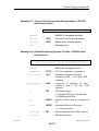
3 - HOW TO USE ALL ADVANCED FUNCTIONS ............................................ 3-1
3-1 The Differential mode .................................................................................
3-1-1 Introduction........................................................................................
3-1-2 Viewing the status of DGPS stations .................................................
3-1-3 Selecting differential stations .............................................................
3-1-4 Kart processing..................................................................................
3-1-5 DGPS processing ..............................................................................
3-1-6 Viewing/updating the Station library...................................................
3-1-7 Checking that the selected stations are properly received ................
3-1-8 Displaying DGPS message ...............................................................
3-2
3-2
3-4
3-6
3-12
3-15
3-16
3-21
3-21
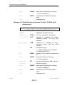
3-2 Waypoints and tracks .................................................................................
3-2-1 Definitions ...........................................................................................
3-2-2 How to read the list of waypoints stored in your receiver ....................
3-2-3 How to create a waypoint from an existing waypoint ..........................
3-2-4 How to create a waypoint from the "NAV" screen ...............................
3-2-5 How to update a waypoint...................................................................
3-2-6 How to delete a waypoint ....................................................................
3-2-7 How to view existing tracks .................................................................
3-2-8 How to define a new track...................................................................
3-2-9 How to delete a track ..........................................................................
3-22
3-23
3-24
3-26
3-27
3-28
3-28
3-29
3-29
3-30
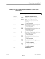
3-3 Navigation modes.......................................................................................
3-3-1 Definitions ...........................................................................................
3-3-2 Graphic screen....................................................................................
3-3-3 How to use the position mode.............................................................
3-3-4 How to use the homing mode .............................................................
3-3-5 How to use the bearing mode .............................................................
3-3-6 How to use the profile mode ...............................................................
3-31
3-31
3-33
3-34
3-35
3-36
3-38
3-4 Intentionally blank....................................................................................... 3-39
3-5 Auxiliary functions.......................................................................................
3-5-1 Status.................................................................................................
3-5-2 Viewing and clearing events and anomalies......................................
3-5-3 Viewing the UKOOA QC data ............................................................
3-5-4 Viewing the software version .............................................................
3-5-5 Initialization ........................................................................................
3-5-6 Unavailable ........................................................................................
3-5-7 Screen brightness..............................................................................
3-5-8 GPS fix mode ....................................................................................
3-40
3-41
3-45
3-46
3-48
3-48
3-54
3-54
3-55
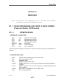
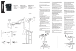
APPENDIX 1 : Installation ................................................................................. A1-1
APPENDIX 2 : Getting started ........................................................................... A2-1
APPENDIX 3 : Connecting a peripheral ............................................................ A3-1
APPENDIX 4 : Differential GPS......................................................................... A4-1
APPENDIX 5 : DATUM ...................................................................................... A5-1
APPENDIX 6 : Allowable commands from a PC................................................ A6-1
APPENDIX 7 : Raw Data................................................................................... A7-1
APPENDIX 8 : Variables accessible using the CONFGPS software in output
messages and user-defined screens
A8-1
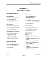
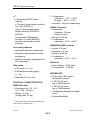
APPENDIX 9 : NR203 Specifications ............................................................... A9-1
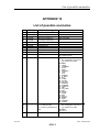
APPENDIX 10 : List of possible anomalies ...................................................... A10-1
WARNING
The accuracy of this receiver is not only dependent on its
performance but also on various external factors (installation
and environmental conditions, handling, use, etc.).
Therefore, it should be used as an aid to navigation rather than
a substitute for a navigator's skill and judgement.
The NR203 is a reliable shipmate that will help you to make
vital decisions in critical situations, but don't let them allow
yourself to believe this relieves you of customary prudence and
navigational care.
NOTICE
DSNP DGPS receivers can use the correction signals
broadcast by the long-range DGPS stations installed by DSNP
on the French territory.
So long as no broadcasts by radio-positioning systems are
taxed in this country, DSNP can offer its customers free
access to the corrections provided by those stations.
However if French regulations changed in the future, to
impose taxation on radiopositioning transmissions, DSNP
would reserve the right to pass on the resulting financial
expenses to the users working with those stations.
Introduction
1 - INTRODUCTION
1-1 ABOUT THE NR203 RECEIVER
Multidifferential
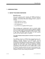
All-in-view real-time survey receiver, the NR203 integrates a
powerful multi-frequency, multi-station correction receiver
capable of processing differential messages from a variety of
sources :
•
DSNP NDS200 HF Station
•
DSNP NDS100 UHF Station
•
IALA Radiobeacon
•
Any RTCM 104 compatible DGPS system
The corrections are subsequently used to compute either
KART and EDGPS positions (when phase data are available)
or up to 4 single station solutions (when only PRCs available)
then mixed in an optimized multistation DGPS solution. Thus,
in any case the NR203 gives the user the best possible
position with the highest degree of reliability.
The most advanced and powerful real-time survey receiver
available.
The NR203 is based on DSNP latest high-performance 15channel GPS core and is fully compatible with industry
standards (RTCM, UKOOA, etc.). It makes use of
sophisticated statistical testing and quality control procedures
to guarantee the reliability of results. Furthermore, it delivers
high-rate raw GPS data and includes advanced facilities
including a 1 pps output, and 3 event trigger inputs. A fully
programmable serial interface able to accommodate virtually
all industry standard protocols as well as non-standard userspecific requirements is also included to guarantee a smooth
integration into the user's working environment.
0311357
Issue : September 1997
1-1
Introduction
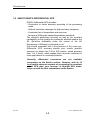
1-2 ABOUT DSNP'S DIFFERENTIAL GPS
DSNP's Differential GPS provides :
- Centimetric to metric accuracy according to the processing
mode,
- Optimal correction messages for high-accuracy navigation,
- A coherent line of transmitters and receivers,
- Numerous Differential transmitting stations worldwide.
The absolute positioning accuracy as well as the excellent
repeatability of the system are continually afforded whether the
SA (Selective Availability under the control of the US
Department of Defense) is activated or not.
One should remember that in the presence of SA, most nonDifferential GPS receivers provide poor results (position
accuracy no better than 100 to 500 metres, speed accuracy
from 1 to 2 knots), which makes those receivers inefficient in
most applications on continental shelves.
Naturally, differential corrections are not available
everywhere on the Earth's surface. However, with its 15
true parallel channels capable of processing the complete
set of GPS data, your receiver, in Straight GPS mode,
keeps up with the best competitors on the market.
0311357
Issue : September 1997
1-2
Introduction
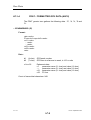
1-3 ABOUT THIS MANUAL
The present manual includes two major chapters :
- Chapter 2 takes you to the standard navigation display in
just one step : pressing the ON/OFF key. The standard
navigation display provides basic navigation data (position,
course, speed, quality figure) which are continually visible on
the screen (even when other navigation functions are being
used).
- Chapter 3 teaches you how to use the available navigation
functions (HOMING, ROUTES) and auxiliary functions.
These two chapters are summarized in the User's Quick Guide
accompanying this manual.
Appendices provide general support information in connection
with the use of your receiver :
-Installation,
-Connection to a peripheral,
-The Differential technique,
-Datum's,
-receiver specifications, etc.
Conventions used in this manual
The following symbols are used to represent the arrow keys :
[↑]
for
[←]
for
[↵]
[↓]
for
[→]
for
for
0311357
Issue : September 1997
1-3
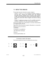
Introduction
1-4 HOW TO USE THE KEYBOARD
On/Off key
DIF
Function keys
NAV
AUX
MARK pushbutton
MRK
WPT
7
8
9
4
5
6
1
2
3
Numeric
keypad
NAV
AUX
Arrow keys
10
Saves or gives access to
data that can be updated via
the keyboard
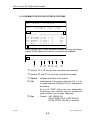
Pressing a function key causes a specific menu to show up in
the lower part of the screen.
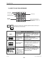
WPT
WHEN THE CURSOR RESTS :
KEYS
on a menu at the
bottom of the
screen
on a character or option that you
are allowed to update ("[↵
↵] Valid"
is prompted)
Move the cursor
horizontally within
the menu
Move the cursor to the next
characters or options that you are
allowed to update
Scroll through the possible values for
a character or option. Possible values
for an alphanumeric character are :
Scroll through the
display pages
7
STU
8
VWY
4
JKL
9
YZ−
5
6
MNO
PQR
1
ABC
2
DEF
3
GHI
0
- figures from 0 to 9
- upper-case letters A to Z
- characters + - .*/ : and "space".
Direct choice within
a menu.
The [0] key may act
as an EXIT key,
taking you back to
the previous menu
or step
Entry of a permitted numeral if the
cursor rests on a character entry field.
Entry of a letter (1 of 3) within an
alphanumeric field.
0311357
Issue : September 1997
1-4
Introduction
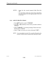
How to select a menu
In the procedures described throughout this manual, you will
be required to press a function key ([NAV] or [AUX] or [WPT])
and to select a menu.
- For example, if you are required to :
Press [AUX] and select "5-Init" then "2-Position".
You only need to press [AUX] then [5] then [2].
The direct method above allows you to rapidly access any
menu (or submenu).
- The cursor may be prepositioned on the field you are most
likely to wish to change. In that case you only need to press
[↵] to select the highlighted choice number, or press the
desired key to select another choice number (you may also
use [→] or [←] to move the cursor to the desired choice
number then press [↵]).
Depending on the context, the two equivalent procedures :
- take you to a submenu or a display
- or cause the immediate performance of an action
- or take you to fields and/or options that you are allowed to
update.
0311357
Issue : September 1997
1-5
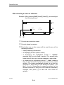
Introduction
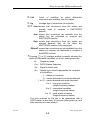
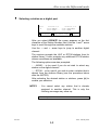
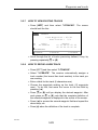
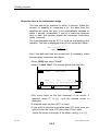
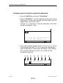
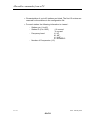
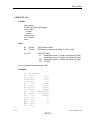
After selecting a menu or submenu
Example : After pressing [AUX] then [5] then [2], you should get
the following screen :
AUX
INIT
Q
POSITION
Lat
47°16N
R
Lon
1°29W
Ýß = SCANNING <>=PREV/NEXT FIELD ↵ =VALID
S
U T
Q
R
S
Current menu selection steps
Current values in memory
The bottom row on the screen will be used for any of the
following purposes :
- simply displaying information
- or displaying a menu (with a cursor)
- or displaying the highlighted prompt "↵ Update"
meaning that you only need to press [↵] to access entry
fields that will allow you to make changes to some data.
- or displaying the highlighted prompt "↵ Valid" meaning
that you are allowed to update some parameters and/or
options. The cursor automatically shows up on the first
character or entry field you are allowed to update : use
the [→] or [←] arrow key to move the cursor to the
desired character or entry field, and make the necessary
changes, then press [↵] to save the new values or
options.
0311357
Issue : September 1997
1-6
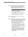
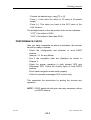
Introduction
T
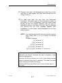
Whenever the data to be displayed are in the form of a list
(with two or more pages) you may scroll through the list,
using [↓] and [↑].
U
For each entry field, you can enter only authorized
characters. The value typed on the keyboard is tested as
you press [↵]. If it is inconsistent, then the cursor keeps
blinking on the first suspect character until you type an
authorized value or you leave the entry field by pressing
any function key. (An error message appears, selfexplanatory in some cases, which disappears as you next
press any key).
NOTE : In an alphanumeric field, you may use the numeric
keys rather than [↑] or [↓] to enter the desired
letters.
Example, pressing :
[1] will enter "1"
[1] [1] will enter "A"
[1] [1] [1] will enter "B"
[1] [1] [1] [1] will enter "C"
[1] [1] [1] [1] [1] will enter "1" and so on ...
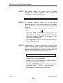
NOTICE
Whenever you wish to terminate the step in progress, simply
press any function key.
Pressing the [0] key allows you to quit some dialog screens
(unless a numeric entry field is selected). This takes you back
to the screen that initiated the dialog.
Pressing the [0] key also allows you to move up one step in
any menu.
0311357
Issue : September 1997
1-7
Introduction
0311357
Issue : September 1997
1-8
Standard Navigation
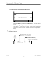
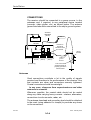
2 - STANDARD NAVIGATION
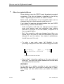
• Your receiver is very easy to use : simply press the ON/OFF
key...
...and that's all ! All the parameters required at power-up
(position last computed, selection of a Differential GPS
station, etc.) were saved to the non-volatile memory when
the receiver was last turned off.
In most cases, you will not need to care about those
parameters when you turn it back on.
Furthermore, the date and time, continually updated during
power outages, are available straight away at power-up.
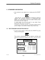
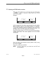
2-1 THE STANDARD NAVIGATION DISPLAY
• To turn on the receiver, briefly press the ON/OFF key (top
left key in the keypad).
The receiver automatically runs its power-on self-test and
retrieves the parameter settings saved when it was last turned
off.
DSNP
PWES1
VX X
PWES1
Addr bus
Data bus
Flash test
GPS03
VX X
IDxx
COMPLETED
COMPLETED
COMPLETED
DIF03x
VX.X
DIF03
Addr bus
Data bus
Flash test
IDxx
COMPLETED
COMPLETED
COMPLETED
0311357
GPS03
IDxx
Data mem. COMPLETED
Main Osc. COMPLETED
Math Copr. COMPLETED
Asic GP1 COMPLETED
Asic GP2 COMPLETED
Asic GP3 COMPLETED
Issue : September 1997
2-1
Standard Navigation
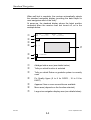
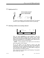
When self-test is complete, the receiver automatically selects
the standard navigation display (providing the data helpful to
most navigators most of the time).
At power-up, the standard display shows the latest position
computed when the receiver was last turned off, as in the
example below.
Q
R
S
T
U
V
Aug 13
1996
UTC
10:27:05
AUTO
.GPS.
3D 08/10SVs
NAV
WGS84
Q
- 1
W
÷ = SCANNING
1-FREEZE
2-MODE
3-GRAPHIC
Q
R
S
Abridged status area (see details below)
T
Fix Quality figure (0 to 9 for DGPS ; 10 to 19 for
KART)
U
V
W
Appears if two or more screenfuls are available
Tells you which function is selected
Tells you which Datum or geodetic system is currently
used
Menu area (depends on the function selected)
Large-size navigation display area (see details below).
0311357
Issue : September 1997
2-2
Standard Navigation
& Large-size navigation display area
Depending on the geodetic system selected (AUX→5→4),
either Latitude/Longitude or Northing/Easting coordinates
may be displayed.
E Latitude/Longitude
Depending on the units selected (AUX→5→6), either a
degrees, minutes or degrees, minutes, seconds format
may be used to display the Latitude and Longitude.
Latitude (d,m)
Course Over
Ground
(see note 1)
47°16.08573 N
1°29.49842 W
***° H 7.45 m
^ 1.3kT
0.2kT
Latitude (d,m,s)
Course Over
Ground
(see note 1)
47°16'08.734 N
1°29'49.426 W
123° H 7.45 m
^ 1.3kT
0.2kT
Horizontal
speed
(see note 2)
Longitude (d,m)
Altitude
Longitude (d,m,s)
Altitude
Vertical speed (the
arrow denotes the
direction)
E Northing/Easting
Course Over
Ground
(see note 1)
N
12345.12
E- 123456.12
***° H 7.45m
0.2kT
^ 1.3kT
Horizontal
speed
(see note 2)
0311357
Northing
Easting
Altitude
Vertical speed (the
arrow denotes the
direction)
Issue : September 1997
2-3
Standard Navigation
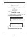
NOTE 1 : *** is displayed if the COG is inconsistent (if the
speed is zero or near zero).
NOTE 2 : Depending on the unit selected (AUX → 5 → 6) the
speed may be expressed in :
knots (kT)
metres/second (m/s)
kilometres/hour (k/h)
NOTE 3 : Selecting FREEZE prevents the display from being
refreshed for about 10 seconds.
The navigation display data are continually visible, either
occupying the large-size navigation display area or shrunk in
the upper part (under the abridged status area).
Aug 12
1996
UTC
07:02:15
WGS84
Q.9
47°16.08951 N ***° H 48.1m
1°29.48802 E 0.2kT ^ 1.9kT
Aug 12
1996
UTC
07:02:15
WGS84
Q.9
AUTO .DGPS1.
3D 08/09SVs
AUTO .DGPS1.
3D 08/09SVs
N
12345.12
E- 123456.12
***° H 48.1m
0.2÷
^ 1.9÷
Shrunk navigation display data (whenever a function
other than the standard navigation display is used).
0311357
Issue : September 1997
2-4
Standard Navigation
&Abridged status area
Type of switching from a Fix Mode to
another (Automatic or Manual switching).
Differential mode used to compute the fix
Blinking if another Differential mode is requested
using [DIF] → 2 or 3 (see par. 3-1-4 or 3-1-5)
- Straight GPS (GPS)
- Conventional Diff (DGPS1, 2, 3, 4 or MDGPS)
- KART (EDGPS, KARTA, KARTR).
Date
Day
Year
Month
Aug 14 1996
UTC 10:27:05
AUTO. DGPS1.
3D 08/10SVs
Time
UTC, or LOC if a local
time offset is used
(see Appendix 2)
Count of satellites received
(SVs for Space Vehicles)
Count of satellites used
Fix Mode :
DR
if Dead Reckoning
HOLD if no position is computed
3D
if 3-dimension computation
2D
if 2-dimension computation
NOTE : "FRZ" or "MRK" appears in the upper right corner
(displayed for about 10 seconds after selecting FREEZE
in the NAVigation menu or pressing MRK on the
keypad).
" Naturally, at power-up no satellite is locked on, so the
count remains at "0" but at the end of 1 to 2 minutes, the
count increases (1, 2...) up to a maximum of 15 SVs. The
receiver processes the 15 best usable satellites
concurrently and completely.
0311357
Issue : September 1997
2-5
Standard Navigation
At the end of 3 to 4 minutes :
- The blinking "HOLD" indicator vanishes (replaced by the
Fixing Mode : 2D or 3D),
- The speed is computed and displayed (along with the
Course Over Ground),
- The position is computed and updated,
- Finally, within an area covered by Differential GPS
stations and depending on the count of SVs received
and on the way they are received, the Differential mode
used is displayed (if no Differential station is received or
the reception level is too weak, whereas the Differential
mode is activated, the Differential mode indicator is
blinking).
If no fix is obtained after 15 minutes of operation, the
"Search in sky" process is started during which the receiver
tries to track all the known satellites, in succession, until a
position solution can be obtained.
" Depending on the configuration of your receiver, one or
more navigation displays are available (standard display
and other displays ; see chapter 3 for more details).
In the case of several displays available, use the [↑] and [↓]
keys to scroll through the different displays.
" During this very simple procedure (simply pressing the
ON/OFF key), special cases may arise that require a few
more actions of an operator :
- entering an initial estimate (see par. 2-2)
- entering the date and time (see Appendix 2).
- selecting another Differential station, or changing the
fixing mode or Differential mode (see Chapter 3).
NOTES : • The keypad is tested at power-on if you press any
key after pressing the ON/OFF key.
• The default GPS and DIF configuration
parameters are restored at power-on if you press
the ↵ key and hold it depressed during the poweron sequence until the DSNP logo re-appears.
0311357
Issue : September 1997
2-6
Standard Navigation
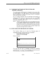
2-2 HOW TO ENTER AN INITIAL ESTIMATE
Entering an initial estimate may be helpful if the ship has
moved more than 1° in latitude or longitude since the receiver
was last turned off. This will substantially shorten the time
required for the receiver to lock on satellites and compute the
first fix.
The initial estimate entry procedure is as follows :
•
After turning on the receiver, wait for the Standard
Navigation Display to show up.
•
Press [AUX] and select the initialization menu (5-Init). For
detailed information on how to use the keyboard, see
par. 1-4.
•
Select the submenu "2-Position" This causes the latest
computed position to show up in the bottom row.
Lat
47°16N
Lon
1°29W
Ýß = SCANNING <>=PREV/NEXT FIELD ↵ =VALID
•
Enter the estimated latitude and longitude (or Northing and
Easting).
•
Check the coordinates keyed in, then press [↵
↵] to validate
your entry. This completes the entry procedure.
•
To call back the previous navigation display, press [NAV]
again.
0311357
Issue : September 1997
2-7
Standard Navigation
2-3 HOW TO TURN OFF THE RECEIVER
•
To turn off the receiver, hold down the ON/OFF key
until the screen becomes blank (about 2 seconds), then
release the key : the receiver is off.
This completes the few actions required to operate the
receiver for standard navigation.
The next chapter is intended for users who wish to take
advantage of all the advanced functions provided by the
receiver.
0311357
Issue : September 1997
2-8
How to use the Differential mode
3 - HOW TO USE ALL ADVANCED FUNCTIONS
The operator is assumed to be familiar with the few actions
required to operate the receiver for ordinary navigation
(described in Chapter 2).
As a reminder, the only steps to be taken, unless you wish to
change something in the parameters displayed, are :
- turning the receiver on or off,
- entering an initial estimate (exceptionally),
- selecting a navigation display.
The present chapter provides detailed information on the
following functions :
- Differential GPS
- Navigation modes and corresponding screens
- Auxiliary functions (purpose and operating instructions).
NOTICE
For detailed information on how to use the keyboard,
see par. 1-4.
Installation instructions, mostly intended for the persons in
charge of setting up and servicing the equipment, are provided
in Appendix 1.
0311357
Issue : February 2000
3-1
How to use the Differential mode
3-1 THE DIFFERENTIAL MODE
Your receiver has been configured to receive the Differential
GPS (DGPS) stations covering your region. (The theory of
operation of Differential GPS is explained in Appendix 4).
3-1-1 Introduction
This paragraph introduces the few key points and definitions
required to understand all the capabilities offered by your
receiver to operate in Differential mode.
" Differential corrections may be input to the receiver through
a radio link or a serial wireline.
- Radio link
Corrections broadcasted in the HF band (DSNP format)
or in the MF band (RTCM format) — received through the
WIDE BAND (or NARROW BAND) antenna connector —
are input to four analog channels.
If an NDR104 UHF receiver is used — optional, on the
NUM connector — corrections received in the UHF band
(DSNP or RTCM format) may also be available.
- Serial line
If an auxiliary receiver is used — connected to the NUM
connector — providing digital RTCM 104 corrections,
four sets of corrections may be available (from four
distinct DGPS stations).
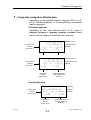
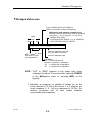
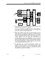
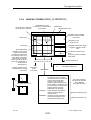
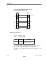
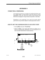
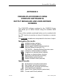
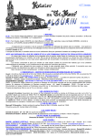
By pressing the DIF key and selecting 1-Select, you can
assign DGPS stations to your receiver's reception channels
thus allowing the processing of up to 6 sets of corrections.
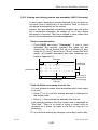
By pressing the DIF key and selecting 2-KART or 3-DGPS,
you can choose the desired Differential mode. From the
available processed corrections (up to 6 sets) you can
generate up to four DGPS positions, and an MDGPS position
(weighted mean DGPS position) or a KART position (EDGPS,
KART A, KART R). Also, you specify the position to be used in
the navigation display.
0311357
Issue : February 2000
3-2
How to use the Differential mode
HF or MF
HF or MF
Channel 1
DIF
DIF
1-Select
Channel 2
2-KART
Wide Band
(or Narrow
Band)
HF or MF
HF or MF
Channel 3
EDGPS
KART A
KART R
Channel 4
Station 1
NUM
Port K
3-DGPS
Station 2
DGPS2
Digital RTCM
Station 3
Station 4
Port L
DGPS1
DGPS3
6 sets of
corrections
DGPS4
MDGPS
UHF (DSNP)
or
Digital RTCM
" The receiver has a non-volatile station library that can hold
the specifications of up to 15 stations.
You can view/change the specifications of the stations in
the library or enter new stations (see par. 3-1-6, which also
covers the case of encrypted stations).
" When the receiver works with an RTCM station (via the
radio channel or a serial port, whichever is used) not only
does it receive the expected corrections from the station,
but also the specifications (coords, type, frequency, etc.) of
nearby stations. You can view the specifications by
pressing DIF and selecting 4-Stations. You may want to
copy the specifications of one of these stations manually
as one of the possible 15 stations saved in the receiver's
non-volatile station library, if there is room for one or more
non-encrypted stations (see par. 3-1-6).
" At power-on, the receiver automatically selects the
stations, Differential mode, Fixing mode that were used
when you last turned it off, and automatically starts
computing the requested position or positions as soon as
the necessary signals are available.
0311357
Issue : February 2000
3-3
How to use the Differential mode
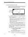
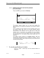
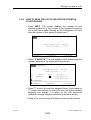
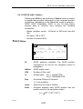
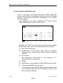
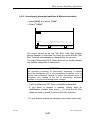
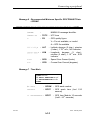
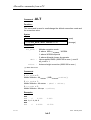
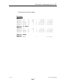
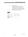
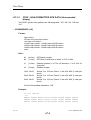
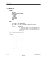
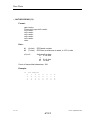
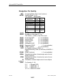
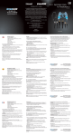
3-1-2 VIEWING THE STATUS OF DGPS STATIONS
Aug 27
1996
UTC
13:06:38
WGS84
AUTO .DGPS1.
3D 08/10SVs
47°16.08951 N
1°29.48802 E
***° H 16.3m
0.4KT ^ 1.4KT
DIF
Station
Chl Fmt Svs Ag Kart Dgps
..........................................
0008 PORSPODER 1+2 SHF 8 10
Used
0012 LA COUBRE 3+4 SHF 9 10
Used
0822 ABERDEEN N L RTCM 8 10
Reje
0821 SCILLY
N L RTCM 7
8
Avai
0014 BREST
N K SUHF 8 10
Avai
1-SELECT 2-KART 3-DGPS 4-STATION 5-MSGES
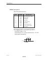
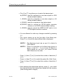
Press the DIF key to view the above screen, showing the status
of each DGPS station from which corrections are available.
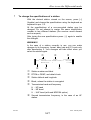
DIF
Station
Q
Chl Fmt Svs Ag Kart
Dgps
RS TU V
W
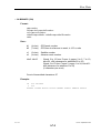
"Columns Q to U tell you how corrections are received.
"Columns V and W tell you how corrections are used.
Q Station
R Chl
S
Fmt
: Number and Label of the station
: Identification of the analog channel (No. 1 to 4)
or digital channel (NUM port K or L) assigned to
the station.
As an HF DSNP station has two transmitting
frequencies, two channels may be assigned to
such a station (one for each frequency).
: Format : SHF (DSNP HF)
SUHF (DSNP UHF or RTCM UHF)
RTCM (RTCM 104, MF or numeric)
0311357
Issue : February 2000
3-4
How to use the Differential mode
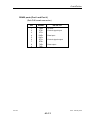
T
SVs
Count of satellites for which differential
corrections are available from the station.
U Ag
Average age of corrections (in seconds)
V/W Used means that corrections from the station
actually used
position.
to
compute
a
are
KART/DGPS
Avai means that corrections are available from the
station but not requested to compute any
KART/DGPS position.
Reje means that corrections from the station are
rejected because they do not allow any
KART/DGPS position to be computed.
íBlanký
ý means that corrections are not available from the
station but anyway not requested to compute a
Kart/DGPS solution.
"Pressing [↑] or [↓] displays another screenful showing the
status of Differential reception on all four analog channels.
B:
Frequency band
Frq : DGPS Station frequency
Sn : Signal-to-Noise ratio
Qu : Quality figure used to appreciate the reception
of corrections :
– 1 : station not received
0 : carrier detected but no words detected
1 to 10 : carrier detected and words decoded:
1 to 3 : very poor reception
(single-frequency station)
4 to 6 : intermittent reception
(single-frequency station)
7 to 10 : good quality reception
(single-frequency station)
The time required for the link to be established with a
DGPS station is less than 30 seconds (after power-up, and
after selection of a new station).
0311357
Issue : February 2000
3-5
How to use the Differential mode
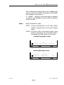
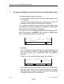
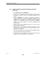
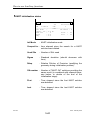
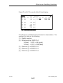
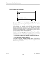
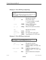
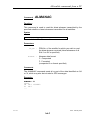
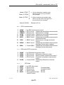
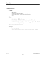
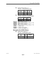
3-1-3 SELECTING DIFFERENTIAL STATIONS
DIF
SELECT
Chl
1
Station
Frq
0008 PORSPODER 1
Band
HF
↵ =UPDATE
Ýß = SCANNING
Press the DIF key and select 1-SELECT to view the above
screen.
Use the Up (↑) and Down (↓) arrow keys to view the stations
assigned to the four analog channels and the two digital ports,
if any.
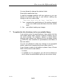
" Analog channels
Input
channel
number
(1 to 4)
Number and label of the station
to be picked up on this channel
Transmission frequency
(1 or 2, for HF station only).
Frequency band (HF or MF)
Chl
1
Station
0008 PORSPODER
Frq
1
0311357
Band
HF
Issue : February 2000
3-6
How to use the Differential mode
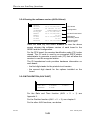
" Digital ports (K, L)
Number and label of the stations
(1 to 4) to be input to this port.
1st row : 1st and 2nd station
2nd row : 3rd and 4th station
Input
Port
(K or L)
Port
K
Station 1/3
14
BREST
0... NONE....
Station 2/4
15
OUESSANT
0... NONE....
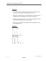
To make any changes, scroll through the list until the desired
channel or port is displayed and select UPDATE (press [↵
↵]).
" Selecting a station on an analog channel
Chl
2
Station
0008 PORSPODER
Frq
1
Band
HF
Ýß =SCANNING <>=PREV/NEXT FIELD ↵ =VALID
After you select UPDATE the cursor appears on the first
character of the Station Number field. Use the ↓ and ↑ arrow
keys to scroll through the available stations. Only the HF or MF
stations are prompted (HF or MF stations whose specifications
have been saved in the non-volatile library).
....NONE.... is also prompted, to be used if you do not wish to
select any station on the channel.
For an HF station, you are allowed to jump to the Frq
(Frequency) field. As HF stations may have two transmission
frequencies, you have to specify the frequency (No. 1 or No. 2)
to be received on the channel. You will be able to assign the
second frequency to another channel.
After selecting the desired station (and frequency, if any) press
[↵
↵] to enable your choice.
0311357
Issue : February 2000
3-7
How to use the Differential mode
NOTE 1 : You cannot select any station that is already
assigned to another channel. This is why the
following message may show up :
Already used here or on another channel !
NOTE 2 : All selected stations should be in the same
frequency band. If one or more stations on another
HF or MF band are selected, the following message
shows up :
Other(s) on another band : Confirm ?
1-YES
2-NO
- Choosing YES enables the station you are
selecting. As a result, any stations on another
band are disabled ("NONE" is assigned to the
corresponding channels).
- Choosing NO cancels your selection and restores
the initial assignment.
NOTE 3 A maximum of 6 sets of corrections (whether from
analog or from digital channels) can be processed.
You are not allowed to add any station if those
already selected amount to 6 sets of corrections. In
that case, the following message shows up :
More than 6 sets of corrections !
- Cancel your choice (press DIF).
- Disable one or more stations, to make room for
one or more sets of corrections
(choose 1-SELECT, select a channel or port,
press [↵
↵], select "....NONE....", and press [↵
↵]).
- Select again the station you wish to add.
0311357
Issue : February 2000
3-8
How to use the Differential mode
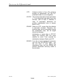
" Selecting a station on a digital port
Port
K
Station 1/3
0014 BREST
0000 NONE....
Station 2/4
0015 OUESSANT
0000 NONE....
Ýß =SCANNING <>=PREV/NEXT FIELD ↵ =VALID
After you select UPDATE the cursor appears on the first
character of the Station Number field. Use the ↓ and ↑ arrow
keys to scroll through the available stations.
Use the → and ← arrow keys to jump to another digital
channel.
The receiver prompts the UHF or RTCM stations from its
station library. It also prompts any additional RTCM station
whose corrections are available.
The following options are also prompted :
- ....NONE.... to be used if you do not wish to select any
station on the digital channel.
-.... RTCM.... to be used if you wish to enter a station that is
absent from the stations library (see the procedure below
after the NOTES).
After selecting the desired station or stations, press [↵
↵] to
enable your selection.
NOTE 1 : You cannot select any station that is already
assigned to another channel. This is why the
following message may show up :
Already used here or on another channel !
0311357
Issue : February 2000
3-9
How to use the Differential mode
NOTE 2: A maximum of 6 sets of corrections (whether from
analog or from digital channels) can be processed.
You are not allowed to add any station if those
already selected amount to 6 sets of corrections. In
that case, the following message shows up :
More than 6 sets of corrections !
- Cancel your choice (press DIF).
- Disable one or more stations, to make room for
one or more sets of corrections
(choose 1-SELECT, select a channel or port,
press [↵
↵], select "....NONE....", and press [↵
↵]).
- Select again the station you wish to add.
NOTE 3 : On each digital port, you should not mix UHF and
RTCM stations.
NOTE 4 : At high input rate, synchronizing the RTCM data flow
causes heavy processing load. In order to guarantee
correct operation of the whole DGPS acquisition, it is
recommended to observe the following rules:
1 – Do not feed the NR203 digital ports with
DGPS data that are not in UHF DSNP format or
RTCM (6 of 8) numeric format.
2 – Do not feed the NR203 digital ports with data
that use transmission characteristics (baud rate,
parity, etc.) different from those programmed on its
serial ports K and L. In addition, do not use baud
rates greater than 9600 Bd.
3 – If demodulators are used to deliver several
corrections sets (this may be a satellite-system
demodulator or any other demodulator), please
limit the number of corrections sets available at
the demodulator output to those really useful in
the working area.
0311357
Issue : February 2000
3-10
How to use the Differential mode
" Entering an RTCM station number
When you select stations on a serial port you may choose the
.... RTCM .... option to reserve a blank field for an RTCM
station (see above).
Example :
Port
K
Station 1/3
0014 BREST
... .RTCM....
Station 2/4
.... RTCM ....
... NONE ....
Ýß =SCANNING <>=PREV/NEXT FIELD ↵ =VALID
In this example the first station was selected from the station
library (whether saved in non-volatile memory or received).
The 2nd and 3rd station fields are available for you to enter the
number of an RTCM station that is not listed in the library. The
4th station field is not to be assigned to any station.
Pressing ↵ again allows you to access the blank RTCM station
number entry fields. The cursor appears on the first blank
RTCM field.
Port
K
Station 1/3
0014 BREST
0000 RTCM....
Station 2/4
0000 RTCM ....
.... NONE ....
Ýß =SCANNING <>=PREV/NEXT FIELD ↵ =VALID
Enter the desired RTCM station number (0000 to 1023), using
the numeric keypad.
Press ↵ to enable your selection.
NOTE :
On each digital port, you should not mix UHF and
RTCM stations.
0311357
Issue : February 2000
3-11
How to use the Differential mode
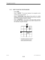
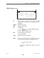
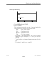
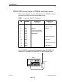
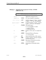
3-1-4 KART PROCESSING (DIF 2-KART)
If corrections including phase corrections are available (from a
DSNP UHF station), your NR203 is capable of computing a
KART position (see Appendix 4 for details).
View current
settings
Change current
settings
DIF
KART
UPDATE
In process :
Mode
Station
OTF
53
SCILLY
Mode
OTF
Station
53
SCILLY
Used
KARTA
Used
K ARTA
Ýß = SCANNING <>=PREV/NEXT FIELD ↵=VALID
"
Pressing the DIF key and selecting 2-KART displays
the above screen that allows you to view and set parameters
for the KART processing :
- KART initialization mode (or EDGPS). If "NONE" is
displayed for the current mode, this means that the
receiver does not use the KART technique. Either the
straight GPS or DGPS mode is used.
- Station to be used (selection from the available sets of
Differential measurements).
- KART position to be used for navigation (selection from
three KART positions computed in different ways).
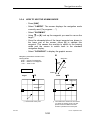
"
The cursor automatically appears on the "Used" field.
Use the arrow keys to go to the desired field and make the
necessary changes, and press [↵
↵]. This enables the new
settings and triggers an initialization sequence If the cursor
is on "Mode" field.
Used : allows you to specify the computed position which is
to be used for the navigation display :
EDGPS or KARTA or KARTR
(see Appendix 4)
If the initialization Mode field is set at EDGPS you
cannot choose KARTA or KARTR.
Station : prompts the first UHF station received or the latest
used. Use ↑ or ↓ to scroll through the stations from
0311357
Issue : February 2000
3-12
How to use the Differential mode
which differential measurements are available that
can be used for the KART processing. Only DSNP
UHF stations are prompted.
If ....NONE.... appears, this means that no suitable
corrections are available and the KART technique
cannot be used.
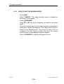
Mode :
KART initialization mode.
INITK : causes reinitialization in the same Mode
(which is viewed in the "In Process" display
area).
POINT : you have to key in the exact position of the
antenna (assuming you have determined it
accurately by some means of your own).
Latitude/Longitude format
Lat
1°23.00000N
Lon
4°56.00000W
H
-0070.000
Ýß = SCANNING <>=PREV/NEXT FIELD ↵=VALID
Northing/Easting format
Northing
+4259105.195
Easting
-310464.000
H
55.9
Ýß = SCANNING <>=PREV/NEXT FIELD ↵=VALID
0311357
Issue : February 2000
3-13
How to use the Differential mode
OTF :
Antenna motion is free. The antenna
position is determined "On The Fly"
(standard mode for sea navigation).
STATIC The antenna should be kept motionless
(± 1 cm along the three axes) for a few
minutes, with at least 5 satellites in
view, to accurately determine its
position. Initialization time is shorter
than in OTF.
ZFIXED Same as OTF, except that the altitude
is assumed constant. Therefore, the
antenna may move horizontally during
the initialization step, but its height
should not change.
Initialization is easier than in STATIC
mode but requires that one more
satellite be used. Time required for
initialization between Static and OTF.
EDGPS : If you do not need centimetric accuracy
you can use the EDGPS mode : you
will not have to care about any
initialization step, still your NR203 will
achieve decimetric accuracy within a
few minutes.
0311357
Issue : February 2000
3-14
How to use the Differential mode
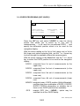
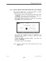
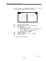
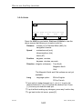
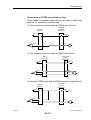
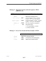
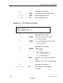
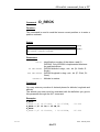
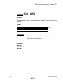
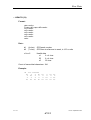
3-1-5 DGPS PROCESSING (DIF 3-DGPS)
DIF
DGPS
UPDATE
DGPS1/DGPS3
0008 PORSPODER
0012 LA COUBRE
DGPS2/DGPS4
....NONE....
....NONE....
Used
DGPS1
Ýß = SCANNING <>=PREV/NEXT FIELD ↵=VALID
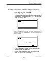
Press the DIF key and select 3-DGPS to view the above
screen that allows you to select up to four sets of
measurements to be used for conventional DGPS and
specify the differential position which is to be used for the
navigation display.
With the cursor resting on the 1st or 2nd (upper row) or 3rd or
4th (lower row) station selection field, use the ↑ or ↓ arrow key
to scroll through the available differential measurements.
With the cursor resting on the Used field, use the ↑ or ↓ arrow
key to select the DGPS position to be used for the navigation
display :
DGPS1 : computed from 1st set of measurements (in the
upper row)
DGPS2 : computed from 2nd set of measurements (in the
upper row)
DGPS3 : computed from 3rd set of measurements (in the
lower row)
DGPS4 : computed from 4th set of measurements (lower
row).
MDGPS : weighted mean DGPS position (Multi-differential),
resulting from the combination of DGPS1, DGPS2,
DGPS3, DGPS4 (depending on whether two or
three or four DGPS positions are available).
.GPS.
: straight GPS (the ....NONE.... option may be
selected for all four DGPS fields).
0311357
Issue : February 2000
3-15
How to use the Differential mode
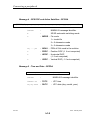
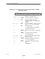
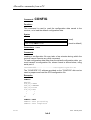
3-1-6
VIEWING/UPDATING THE STATION LIBRARY
(DIF 4-STATIONS)
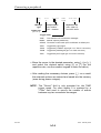
Press the DIF key and select 4-Stations.
DIF
STATION
Station
Type
0010 LA-CRAU
SERC
50b/s
Code 3 H1630000Hz H2635000Hz
Position
43°08N
6°03E
Ýß = SCANNING <>=PREV/NEXT FIELD ↵=UPDATE
The above screen allows you to view and update the
specifications of the stations contained in the receiver's station
library.
Only 15 stations can be saved in the non-volatile memory, but
the station library has room for 30 more stations whose
specifications are received via the radio link or from the
numeric input. If corrections are available from any stations
that are not saved in the non-volatile memory, those stations
are prompted too. (The station library may contain up to 45
stations).
The above screen shows an encrypted station, with two
transmission frequencies (hence a DSNP HF station). For an
non-encrypted station with a single frequency the screen would
look like the one below.
0011
"
Station
Type
Position
GATTEVILLE RTCM 100b/s 49°42N
M0297500
*
1°16W
To view the specifications of a station
Use the ↓ and ↑ arrow keys until the desired station is
displayed.
0311357
Issue : February 2000
3-16
How to use the Differential mode
"
To change the specifications of a station
With the desired station viewed on the screen, press [↵]
(Update) and change the specifications using the keyboard as
explained in par. 1-4.
All the specifications of a non-encrypted station may be
changed. Do not attempt to assign the same identification
number to two different stations (the receiver would discard
such a request).
After typing the new specifications press [↵] again to enable
the changes.
WARNING !
In the case of a station currently in use, you can make
changes to its frequency, format, baud rate and C3 code only
after deselecting it. Your changes will take effect when you
select the station again.
Q
0011
T
R
S
Station
Type
Position
GATTEVILLE RTCM 100b/s 49°42N
M0297500
*
1°16W
U
V
Q
R
S
T
U
Station number and label
V
Second transmission frequency, in the case of an HF
station.
RTCM or DSNP, and data bit rate
Station latitude and longitude
Blank, unless the station is encrypted
Transmission band and frequency
H : HF band
M : MF band
U : UHF band (with and NDR104 option)
0311357
Issue : February 2000
3-17
How to use the Differential mode
"
To copy specifications received to the non-volatile library area
The station library includes two areas :
- a non-volatile area that may contain the specifications of up
to 15 stations,
- a volatile area that may contain the specifications of up to 30
stations received along with Differential corrections.
If you wish to update the library with any specifications from
the volatile area, scroll through the list of stations in the volatile
area, until the desired station is displayed.
So long as you are scrolling through the non-volatile area the
label of the ↵ key is UDPATE. This changes to COPY when
you are scrolling through the volatile area.
Station
xxxx .
MXXXXXXXHz
Type
RTCM
*
XXb/s
Position
XX XXN
X XXE
↵ =COPY
Ýß =SCANNING
• Press [↵
↵]
If all 15 stations in the non-volatile area are encrypted, you
are not allowed to make any change (apart from changing
the access code). As a result the COPY key label is
dimmed.
If that is not the case the screen should look like this :
Station
xxxx .
OVERWRITE
Station
0012 PORSPODER
Ýß =SCANNING !" PREV/NEXT FIELD ↵ =VALID
The screen now prompts stations from the non-volatile area.
• Use the ↑ and ↓ arrow keys to scroll through the non-volatile
area and select a memory location you do not mind erasing
(encrypted stations are not prompted).
0311357
Issue : February 2000
3-18
How to use the Differential mode
You are allowed to change the station's label.
Press [↵
↵] to enable the copy.
A warning message appears with two options so you can
choose to confirm the copy or quit without making any
change to the non-volatile area :
Previous data will be lost. Confirm ?
1 - Yes : overwrite the specifications of the station selected
in the non-volatile area with those from the volatile
area.
2 - No : quit without making any change.
"
To update the list of stations in the non-volatile library
If you wish to enter the specifications of any station into the
non-volatile library area, choose a memory location you do
not mind erasing. For example, choose a saved station
which is of no interest (e.g. because it is too far away), press
↵ (UPDATE) and overwrite its specifications with those of
the new station.
You are not allowed to make any change to an encrypted
station, apart from changing the access code (code 3).
If you choose to enter a new station in place of any of those
listed, make sure the new station :
- is nearer,
- is available (if it is encrypted, you will not be allowed to
use it unless the administrator gives you an access code).
0311357
Issue : February 2000
3-19
How to use the Differential mode
"
About encrypted stations
Some stations using the DSNP format broadcast encrypted
corrections. This type of station is identified in the list by
"code 3" appearing on the left of the station number.
None of the specifications of an encrypted station can be
changed (only your client support centre can do it).
If you intend to insert an encrypted station into your DGPS
station library, consider what follows :
- If the encryption code was not changed at the station
since your receiver was last configured, then nothing
particular is required to use this station, compared to a
non-encrypted station.
- But if the encryption code was changed since then, you
should key in the new C3 code for this station (if you are
allowed to use the station, the station's administrator
should have sent it to you).
• To enter a new code, press [↵] (Update). In our
preceding example the lower line would change as follows
:
Station
0010
LA-CRAU
000000 H1630000Hz
Type
Position
SERC 50 b/s
43 08N
H2635000Hz
6 03E
Enter the C3 code into this field
• Key in the 6 characters making up the new code and
press [↵
↵]. The new code is then saved and the initial data
are restored in the lower line.
WARNING !
In the case of a station currently in use, you need to
deselect the station first if you want to change the C3 code.
The change will take effect when you select the station
again.
0311357
Issue : February 2000
3-20
How to use the Differential mode
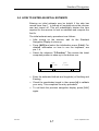
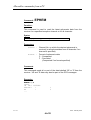
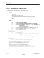
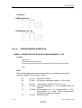
3-1-7 CHECKING THAT THE SELECTED STATIONS ARE
PROPERLY RECEIVED
The quality of the DGPS signal is indicated on the screen after
you press [DIF], in the "Ag" column. Check that the average
age of corrections is correct ("Ag" figure reset to 0 whenever
new corrections are received).
Up to 4 analog channels can be monitored concurrently by
reading the "Qu" column on the screen after you press [DIF]
then [↑
↑]. The quality figure ("Qu") should be interpreted as
previously explained in par. 3-1-2.
NOTE :
Reading a good quality figure and a good signal-to-noise ratio
on your receiver display does not mean that DGPS corrections
are necessarily available. Indeed, reception can be correct
whereas the C3 code you have entered is wrong. In this case
however, corrections won’t be decoded. This operational status
will result in an abnormally high corrections refresh rate
(reported in the "Ag" column, see above).
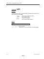
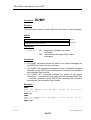
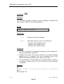
3-1-8 DISPLAYING DGPS MESSAGES (DIF-5-MSGES)
This function allows you to view the following types of
messages received, including the time of reception :
RTCM 104 message, type 16
DSNP HF user message
Screen example :
DIF
MSGES
Aug 25 1997 UTC 14:42:51
0005212 C
Station 0001 1
You can view the last 8 messages received by pressing
repeatedly the ↑ or ↓ key. These messages are those received
from any station, including non-selected stations.
0311357
Issue : February 2000
3-21
How to use the Differential mode
0311357
Issue : February 2000
3-22
Waypoints and tracks
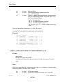
3-2 WAYPOINTS AND TRACKS
3-2-1 DEFINITIONS
Waypoints are defined as particular locations holding interest
in terms of navigation (locations of buoys, fishing spots, work
marks, emergency destinations, dangerous spots, etc.)
A wapyoint is defined by :
- a waypoint number (00 to 99)
- a label (7 alphanumeric characters)
- a type (optional) represented by an icon
- X-Y or L-G coordinates (a 2D position)
The number of possible waypoints in your receiver has been
configured using CONF203 (max. 100). Using this software,
waypoints may also have been created. An additional feature
offered by CONF203 is that you can create "protected"
waypoints which cannot be deleted at receiver level.
Waypoints can also be created in the receiver provided
waypoint numbers still remain free. They can also be updated
or deleted provided they are not protected waypoints.
Waypoint No. 00 cannot be part of a track definition as the
number " 00" is used to inform the receiver of the end of a
track (see below).
0311357
Issue : September 1997
3-23
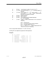
Waypoints and tracks
Tracks are defined as series of waypoints (up to 12 waypoints
per track) representing routes along which to navigate. The
path between any two successive waypoints is called a
"segment".
A track is defined by :
- a track number (1 to 9)
- a label (8 alphanumeric characters)
- a series of waypoints numbers (up to 12 ; if a track consists
of n waypoints, where n < 12, enter "00" in the (n+1) field to
indicate the end of the track, that is why waypoint No. 00
cannot be part of a track definition).
Up to 9 tracks can be stored into the receiver. Tracks can be
defined using CONF203 or at receiver level.
The purpose of storing waypoints and tracks into your receiver
is to guide you to these waypoints or along these tracks by
choosing the appropriate mode (see par. 3-3).
0311357
Issue : September 1997
3-24
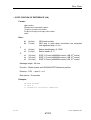
Waypoints and tracks
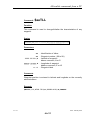
3-2-2
HOW TO READ THE LIST OF WAYPOINTS STORED IN
YOUR RECEIVER
• Press [WPT]. The screen displays the number of free
memory locations (i.e. the number of free waypoint numbers)
out of the total number allowed by the configuration file and
also the number of free tracks (9 tracks max.).
WPT
Free Waypoints : 85/99
Free Tracks : 7/9
1-FREEZE
2-WAYPTS
3-TRACKS
• Select "2-WAYPTS". The first waypoint (with lowest waypoint
number) appears in the lower part of the screen.
WPT
WAYPTS
Free Waypoints : 85/99
Free Tracks : 7/9
No
01
Label
NANTES
Type
Position
47°16.09157 N
1°29.48196 W
Ýß=SCANNING
1-UPDATE
2-DELETE
3-CREATE
• Press [↑] to scroll through the waypoint library. Each press on
[↑] causes the receiver to search for the next higher existing
waypoint and display it in place of the one previously
displayed (a single waypoint definition is shown at a time).
• Press [↓] to scroll through the library in the reverse direction.
0311357
Issue : September 1997
3-25
Waypoints and tracks
3-2-3
HOW TO CREATE A WAYPOINT FROM AN EXISTING
WAYPOINT
• Press [WPT] and then "2-WAYPTS"
• Press [↓] or [↑] repeatedly until the definition of the waypoint
from which you want to create a new waypoint appears on the
screen.
• Press "3-CREATE". The receiver automatically assigns a
waypoint number (the lowest free waypoint number) to the
waypoint you are creating. You cannot choose the waypoint
number for a waypoint that you create from the NR203
keypad. The cursor appears on the first modifiable field
("Label" field).
• Enter a label for your waypoint (see par. 1-3 how to enter
alphanumeric characters).
• Enter a type for your waypoint (optional). Choose one of the
available icons, using [↓] or [↑], as a visual indication on the
nature of your waypoint.
• Enter the coordinates of your waypoint in the geodetic system
currently selected (see top of the screen)
• Press [↵
↵] to create the waypoint. The screen then shows this
waypoint from the updated library of waypoints.
0311357
Issue : September 1997
3-26
Waypoints and tracks
3-2-4
HOW TO CREATE A WAYPOINT FROM THE "NAV" SCREEN
This function allows you to save the position currently
displayed on the NAV screen as a waypoint.
- From the NAV screen, and whatever the mode used, select
"1-FREEZE". This causes the FRZ indicator to show up in
the abridged status line at the top of the screen.
- Before this indicator vanishes (i.e. in the next 10 seconds)
press [WPT]. The screen looks like this :
WPT
WAYPTS
CREATE
Free Waypoints : 85/99
Free Tracks : 7/9
No
01
Label
10:05:5
Ýß=SCANNING
Type
Position
47°16.01234 N
1°29.56789 W
<>=PREV/NEXT
FIELD
↵=VALID
The lowest free waypoint number is prompted to be
assigned to the waypoint you want to create (no other
choice is possible).
- Change the label if necessary (default : time when you
selected "1-FREEZE").
- Press [↵
↵] to create the new waypoint.
Note : You can "freeze" the current position also from the
[WPT] screen.
0311357
Issue : September 1997
3-27
Waypoints and tracks
3-2-5
HOW TO UPDATE A WAYPOINT
• Press [WPT] and then select "2-WAYPTS"
• Press [↑] or [↓] repeatedly until the desired waypoint is
displayed.
• Select "1-UPDATE". The cursor shows up on the first
character in the "Label" field.
If the waypoint is part of a track or is involved in the
navigation mode currently used, the blinking message "Wpt in
use or in track : Confirm update ?" shows up.
• Make all the necessary changes to the label, type and
coordinates.
• Press [↵
↵] to store the new definition of the waypoint.
3-2-6
HOW TO DELETE A WAYPOINT
• Press [WPT] and select "2-WAYPTS"
• Press [↑] or [↓] repeatedly until the desired waypoint is
displayed
• Select "2-DELETE".
• Select "1-YES" to confirm your choice (otherwise select "2NO"). The waypoint is removed from the waypoints library.
NOTE : You cannot delete a "protected" waypoint (Delete
command dimmed when you display this waypoint) or
any waypoint part of a track or involved in the
navigation mode currently used.
0311357
Issue : September 1997
3-28
Waypoints and tracks
3-2-7
HOW TO VIEW EXISTING TRACKS
• Press [WPT] and then select "3-TRACKS". The screen
should look like this.
WPT
TRACKS
Free Waypoints : 85/99
Free Tracks : 7/9
No
01
Label
ST NAZAIR
Waypts
01 02 04 03 05 00
00 00 00 00 00 00
Ýß=SCANNING
1-UPDATE
2-DELETE
3-CREATE
• Scroll through the list of tracks previoulsy defined, if any, by
pressing repeatedly [↑
↑] or [↓
↓].
3-2-8
HOW TO DEFINE A NEW TRACK
• Press [WPT] and then select "3-TRACKS".
• Select "3-CREATE". The receiver automatically assigns a
track number (the lowest free track number) to the track you
are creating.
• Enter a label for the track (8 characters max)
• Choose the waypoints making up the track (12 waypoints
max.). To do this, first move the cursor to the first field by
pressing [→
→].
• Press [↑
↑] or [↓
↓] until you display the desired waypoint. After
each press on [↑
↑] or [↓
↓], note that the complete definition of
the selected waypoint is displayed in the centre of the screen.
• Press [→
→] to access the second waypoint field and repeat the
above step, etc.
• Press [↵
↵] when the definition of the track is complete.
0311357
Issue : September 1997
3-29
Waypoints and tracks
NOTES : - Leave the last unused waypoint fields filled with
"00".
- You can define a track as a close loop by specifying
the same waypoint at the beginning and at the end
of the track.
3-2-9
HOW TO DELETE A TRACK
• Press [WPT] and then select "3-TRACKS"
• Press [↑
↑] or [↓
↓] repeatedly until the track you want to delete is
displayed.
• Select "2-DELETE". The blinking message "Delete this track :
Are you sure ?" appears.
• Select "1-Yes" to confirm your choice (otherwise "2-NO")
NOTE : You cannot delete a track if it's currently followed by the
receiver (Profile mode currently active along this track).
0311357
Issue : September 1997
3-30
Navigation modes
3-3
NAVIGATION MODES
3-3-1
DEFINITIONS
The positioning and navigation information you get from your
NR203 depends on two different factors :
- The configuration of your receiver, which defines the
content, aspect and number of alphanumeric displays (not
including the standard navigation display(s) and the graphic
screen). These displays are independent of the navigation
mode selected.
- the navigation mode you select on your receiver. Depending
on this choice, additional information is provided on a chart
from which you can deduce steering instructions (see
graphic screen in the next paragraph).
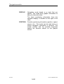
HOMING : Navigation mode based on a waypoint that you
specify. This mode provides graphic information
to help you reach that point along a great circle.
The basic positioning information (from the
standard display) is recalled on the right of the
chart.
BEARING : Navigation mode also based on a waypoint that
you specify. This mode provides graphic
information to help you reach that point
according to the bearing angle defined by the
waypoint location and your current location when
you select this mode.
The basic positioning information (from the
standard display) is recalled on the right of the
chart.
0311357
Issue : September 1997
3-31
Navigation modes
PROFILE : Navigation mode based on a track that you
specify. This mode plots graphic information to
help you follow this track.
The basic positioning information (from the
standard display) is recalled on the right of the
chart.
POSITION : Provides positioning information (position, speed,
course, etc.). This mode can be used when no
further navigation information is required. The
mobile position and the possible waypoints
nearby are however shown on the graphic
screen.
0311357
Issue : September 1997
3-32
Navigation modes
3-3-2
GRAPHIC SCREEN
Centre of square indicates
the location of a waypoint
[NAV] [3-GRAPHIC]
Small blinking square
indicates the current position
of the mobile
Mobile trace
Abridged status area
Information from standard
navigation display recalled
in this area
Centre point
Navigation mode
currently used
Scale used
These dotted lines
(invisible on the screen)
represent the limits of
plotting area. Whenever
the mobile crosses one of
these limits, the receiver
switches to the adjacent
section of chart (up, down,
left or right, depending on
the direction of
displacement).
Example: Mobile moving
downward and crossing
down limit:
Navigation parameters, target
waypoint, relative to mode
used
0.02 NM
1-SCALE
Chart scale,
in NM
(or in m/km)
Yf
Screen skips over to
down-adjacent section of chart:
2
2-PLTMODE
3-OPTIONS
Remember you can press [0]
to go back to the previous menu
1
Yf
Coordinates of centre point,
other...
([↑] and [↓] active in Bearing
and Profile)
4-CLEAR
Clears mobile trace
1- w nn : Show/Hide waypoint numbers
2- .....* : Show/Hide mobile trace
Plot Modes
1-NORTH : North/West-oriented chart with
no particular point or direction
held fixed, first built on the basis
of the mobile position when
running a new mode (this
position is plotted at the centre
point), and then re-adjusted only
if the mobile moves beyond the
position plotting area (see
explanations on this page)
2-TARGET : Target waypoint held fixed at
centre point (North/Westoriented chart)
3-SEGMENT : Segment currently followed is
the central vertical line (not a
North/West-oriented chart)
0311357
All modes (the North
axis gives the direction
of the WGS84
Geographical North)
Bearing and Homing only
Bearing and Profile only
Issue : September 1997
3-33
Navigation modes
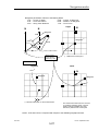
3-3-3
HOW TO USE THE POSITION MODE
- Press [NAV]
- Select "2-MODE". The screen displays the navigation mode
currently used ("In progress : ..).
- Select "1-POSITION". This causes the receiver to switch
immediately to the POSITION mode and the screen to switch
back to the standard navigation display.
- Select "3-GRAPHIC" if you want to plot the position solution
on a chart. No further information is provided compared with
the standard navigation display.
N
N
Waypoint
W
Mobile
(1)
(1)
The mobile trace starts from the moment
you select the Profile mode. The first
position solution available from that
moment is plotted at the centre point.
0311357
Issue : September 1997
3-34
Navigation modes
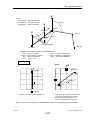
3-3-4
HOW TO USE THE HOMING MODE
- Press [NAV]
- Select "2-MODE". The screen displays the navigation mode
currently used ("In progress : ...")
- Select "2-HOMING"
- Using [↑
↑] or [↓
↓], look up the waypoint you want to use as the
target :
- Once the characteristics of the target waypoint are shown in
the lower part of the screen, press [↵
↵] to validate this
waypoint. This causes the receiver to switch to the homing
mode and the screen to switch back to the standard
navigation display.
- Select "3-GRAPHIC" to display the graphic screen.
N
Navigation parameters relevant to the
Homing Mode:
CTW : Course To Waypoint
DTW : Distance To Waypoint
TTG : Time To Go
Waypoint
CTW
DTW
Plot Modes
Mobile
N
Target
N
North
N
N
Waypoint
Waypoint
(1)
Mobile
W
(2)
W
(1)
(2)
Held fixed at centre point
0311357
The mobile trace starts from the moment
you select the Homing mode. The first
position solution available from that
moment is plotted at the centre point
Issue : September 1997
3-35
Navigation modes
3-3-5
HOW TO USE THE BEARING MODE
- Press [NAV]
- Select "2-MODE". The mode currently used is indicated on
the screen ("In progress : ...")
- Select "3-BEARING".
- Using [↑
↑] or [↓
↓], look up the waypoint you want to use as the
target :
- Once the characteristics of the target waypoint are displayed,
press [↵
↵] to validate this waypoint. This causes the receiver to
switch to the bearing mode. The course to steer (CTS) is
computed from the current position and then the screen
switches back to the standard navigation display.
- Select "3-GRAPHIC" to display the graphic screen.
0311357
Issue : September 1997
3-36
Navigation modes
Navigation parameters relevant to the Bearing Mode:
CTS : Course To Steer
CTW : Course To Waypoint
XTE : Cross Track Error
DTW : Distance To Waypoint
ATD : Along Track Distance
TTG : Time To Go
N
N
Target
N
N
Waypoint
ATD
Waypoint
CTS
DTW
CTW
(1)
W
XTE
Current mobile location
Mobile location
when selecting
the Bearing mode
(1)
Held fixed at centre point
Plot Modes
Segment
CTS
North
(2)
N
N
Waypoint
Waypoint
W
(2)
Direction held fixed on central vertical line
(3)
Mobile
(3)
The mobile trace starts from the moment
you select the Bearing mode. The first
position solution available from that
moment is plotted at the centre point
NOTE : CTS and CTW are computed with respect to the WGS84 geographical North.
0311357
Issue : September 1997
3-37
Navigation modes
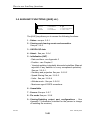
3-3-6
HOW TO USE THE PROFILE MODE
- Press [NAV]
- Select "2-MODE". The screen displays the navigation mode
currently used ("In progress : ...")
- Select "4-PROFILE"
- Using [↑
↑] or [↓
↓], look up the track you want to follow.
- Using [→
→] or [←
←], specify the direction of travel along the
track (direct or reverse).
- Press [↵
↵] to validate the track. This causes the receiver to
switch to the Profile mode and the screen to switch back to
the standard navigation display.
• - Select "3-GRAPHIC" to display the graphic screen.
0311357
Issue : September 1997
3-38
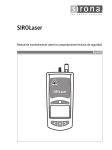
Navigation modes
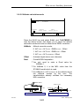
N
Track:
1st segment : WPTaa-WPTbb
2nd segment : WPTbb-WPTcc
3rd segment : WPTcc-WPTdd
NCTS
N
WPTbb
ATD
N
WPTcc
CTS
DTW
CTW
XTE
Mobile location
WPTdd
WPTaa
Navigation parameters relevant to the Profile Mode:
CTS : Course To Steer
CTW : Course To Waypoint
NCTS : Next Course To Steer
DTW : Distance To Waypoint
XTE : Cross Track Error
ATD : Along Track Distance
TTG : Time To Go
Plot Modes
North
Segment
N
N
WPTbb
WPTbb
Segment
(1)
W
Mobile
(2)
WPTaa
WPTaa
(1)
(2)
Direction held fixed on central vertical line
The mobile trace starts from the moment
you select the Profile mode. The first
position solution available from that
moment is plotted at the centre point
NOTE : CTS, CTW and NCTS are computed with respect to the WGS84 geographical North.
0311357
Issue : September 1997
3-39
How to use Auxiliary functions
3-5 AUXILIARY FUNCTIONS ([AUX] KEY)
1-STATUS
4-ABOUT
7-SCREEN
2-ANOMALY
5-INIT
8-FIXMODE
3-QC
6-UNAVAILABLE
9-INP/OUTP
The [AUX] key allows you to access the following functions :
1 - Status: see par. 3-5-1.
2 - Viewing and clearing events and anomalies.
See par. 3-5-2.
3 - UKOOA QC data
4 - About : See par. 3-5-4
5 - Initialization (INIT) :
- Date and time : see Appendix 2
- Position : see Chapter 2
- Viewing/updating intendedly discarded satellites (Manual
rejection of any satellite is a very exceptional operation).
See par. 3-5-5-1.
- Geodesy and projection See par. 3-5-5-2
- Speed filtering See par. 3-5-5-3.
- Units : See par. 3-5-5-4
- Altitude mode : See par. 3-5-5-5
- Maximum age of DGPS corrections
6 - Unavailable
7 - Screen :See par. 3-5-7
8 - Fix mode See par. 3-5-8
9 - Viewing/Updating output port configurations : See
Appendix 3 (information intended for the person in charge
of installing the receiver).
0311357
Issue : February 2000
3-40
How to use Auxiliary functions
3-5-1 STATUS (AUX 1-Status)
Pressing the AUX key and selecting 1-Status causes a screen
to appear that provides information on the computed position
or positions, depending on the Differential mode in progress :
DGPS, KART initialization, KART in use. All three status
screens have a common area showing the following
information :
- Master oscillator source : (INTernal or EXTernal) and drift
rate.
- SA status : ON or OFF.
- Number of received SVS.
"DGPS Status
Ýß
Master Oscill.
SA
Received SVs
INT
0.00E+00
OFF
0
-------------------DGPS----------------Fx Station
USV
Q Dop
Lpme Delta
D1 0013 DSNP 6
1 1.5 14.12 0.00
D2
D3
D4
MD MULTI DGPS 6
1 1.5
14.12 0.00
AUX
Fx
STATUS
: DGPS positions available. The DGPS position
requested to be use for the navigation screen is
highlighted.
Station : DGPS station used.
USV
: Number of SVs used.
Q
: Quality figure
Dop
: Horizontal Dilution of Precision
0 to 3 : straight GPS
4 to 9 : Differential GPS
(-1 if not available).
Lpme
: Mean Error of Lines of Position
Delta
: Deviation between each DGPS position and the
position used for the navigation screen
æç ∆ = ( ∆x ) 2 + ∆y 2 + ( ∆z ) 2 ö÷
( )
è
ø
0311357
Issue : February 2000
3-41
How to use Auxiliary functions
"KART initialization status
Ýß
Oscill.
SA
Received SVs
INT
0.00E+00
OFF
0
-------------------KART----------------Init Mode
:
OK number : x
Comput. for : x.x mn
Used SVs
:
x
First : xs
Sigma
: x.x
Last
: xs
Rdop
: x.x
AUX
Init Mode
STATUS
: KART initialization mode
Comput. for : time elapsed since the search for a KART
solution was initiated.
Used SVs
: Number of SVs used
Sigma
: Standard deviation (should decrease with
time)
Rdop
: Relative Dilution of Precision (qualifying the
geometry during initialization process).
OK number : Number of "KART OK" solutions providing the
same result (is combined with elapsed times,
see below, to decide of the end of the
initialization stage).
First
: Time elapsed since the first KART solution
was detected.
Last
: Time elapsed since the last KART solution
was detected.
0311357
Issue : February 2000
3-42
How to use Auxiliary functions
"KART Status (in use)
Ýß
AUX STATUS
Master Oscill.
SA
Received SVs
INT
0.00E+00
OFF
0
-------------------KART----------------Fx
Station
USV Q Dop lpme Delta
ED 0014 DSNP_UHF
8 13 -1.0 0.03 0.17
KA
8 19 -1.0 0.00
KR
8 19 -1.0 0.00 0.00
Fx
: KART positions available. The KART position
requested to be used for the navigation screen is
highlighted.
Station : DGPS station used.
USV
: Number of SVs used.
Q
: Quality figure
0
11 to 13
14 to 19
Dop
waiting for a consistent EDGPS solution.
EDGPS fix
KART A or KART R fix
: Horizontal Dilution of Precision
(-1 if not computed).
Lpme
: Mean Error of Lines of Position
Delta
: Deviation between KART R and EDGPS solutions
is one of them is used for the navigation screen :
æç ∆ = ( ∆x ) 2 + ∆y 2 + ( ∆z ) 2 ö÷
( )
è
ø
No Delta is computed in relation to the KA
position.
0311357
Issue : February 2000
3-43
How to use Auxiliary functions
Another screenful is accessible by pressing the ↑ or ↓ arrow
key, showing the status of the GPS constellation.
AUX
Ch Sv St Sn Elv Azi
...................
01 03 u 43 ^39 133
02 02 r 28 ^02 040
03 21 u 42 ^36 052
04 23 r 30 ^02 040
05 15 u 47 v49 271
06
07 31 u 47 v78 155
08 14 u 36 ^17 208
Ch
Sv
St
Sn
Elv
Azi
Ýß
STATUS
Ch Sv St Sn Elv Azi
....................
09 27 u 49 v38 171
10 28 u 46 ^12 210
11
12
13
14
15
Receiver channel number
Satellite identification number (PRN Number)
Satellite status :
"s" : Searching for a satellite
"r" : Satellite Received, but not used (Elevation too
low, or no DGPS corrections received).
"u" : satellite received and Used.
Signal-to-Noise ratio
Satellite Elevation (∧ if rising ; ∨ if setting)
Satellite Azimuth
"To quit, press any function key
0311357
Issue : February 2000
3-44
How to use Auxiliary functions
3-5-2 Viewing and clearing events and anomalies (AUX 2-Anomaly)
In most cases, anomalous events detected by the receiver do
not result from a malfunction of the receiver itself, so they do
not appear automatically on the screen.
Instead, they are recorded so that the navigator can look at the
list of anomalies whenever he wishes to, as if they where
recorded in a log book. Then he is allowed to clear (erase from
the list) those anomalies which do not persist.
"How to view anomalies
• Press [AUX] and select "2-Anomaly". If one or more
anomalies are currently reported, the latest two are
viewed first. Scroll through the list of anomalies (if any)
using the [↓] and [↑] arrow keys. ("None" means the list is
empty; all possible anomalies and their meanings are
listed in Appendix 10).
message
AUX
identification
ANOMALY
POSIT No fix computation
0
Begin Aug 19 14:04:15
End 14:13:46
........................................
DIFF
CPU-DIFF overflow
5
Begin Aug 19 14:04:19
End 14:17:20
↵ =ACKNOWLEDGE
Ýß = SCANNING
Beginning day
and time
Additional
error code
End time (or
current time
if persisting)
" How to delete an anomaly from the list
You are allowed to erase those anomalies which have come
to an end :
• Press [↑] or [↓] until the desired anomaly is displayed in
the bottom rows.
• Press [↵] : this removes the anomaly from the list.
If an anomaly persists, then the current time is displayed as
"End time". There is no point in trying to erase such an
anomaly as it shows up again in the list so long as it is
persisting.
" To quit without making any changes, press any function key.
0311357
Issue : February 2000
3-45
How to use Auxiliary functions
3-5-3 Viewing the UKOOA QC data
From V3.0 and only if the NR203 operates in DGPS or MDGPS
mode, a new function is available showing the results of QC tests
(Quality Control tests) performed according to the UKOOA
recommendations.
- Press [AUX] key and select "3-QC". The QC status screen
displays showing the results of the FTEST :
AUX
Fx
D1
D2
D3
D4
MD
QC
Station
FTest
0022 PORSPODE OK
0016 BREST
NOK
0017 XXXXXX
OK
0002 YYYYY
0K
0K
(1)
Ýß
Status
(2)
(3)
DRMS
0.42
6.38
0.36
0.53
0.47
Sv
11
6
12
10
(4)
(5)
MDEmax
0.76
27.19
0.65
0.34
(6)
Basically, the FTEST (or Unit variance test) checks the validity
of the noise model used. The following results are provided :
(1) DGPS Fix identification
(2) Identification of the station from which the position
solution results : station number, label of station assigned
to this fix.
(3) FTest result :
OK displayed if mean value of unit variance is "1"
(otherwise NOK is displayed).
(4) DRMS
(5) Identification of the satellite for which MDE2 max is found.
(6) 2 Dimensional MDE max, in metres.
The maximum value of MDE (Marginally Detectable Error)
is the smallest bias that can be detected by the W-test
with a certain probability.
0311357
Issue : February 2000
3-46
How to use Auxiliary functions
Press [↑] or [↓]. The results of the W-test display :
AUX
Sv D1
07 OK
13 OK
D2
QC
D3
OK
OK
20
OK
OK
24
25
14
OK
OK
OK
OK
NOK
OK
(1)
(2)
(3)
(4)
W-TEST
D4 |Sv D1
|05 NOK
OK |10 OK
|
OK |
|
OK |
OK |
OK |
Ýß
D2
D3 D4
NOK NOK
OK OK
(5)
The W-test is a statistical test performed on observations. The
results of the test are the following :
(1) Satellite number
(2) W-test result on DGPS Fix 1
çW-test ç ≤ 2.576 → OK (good)
çW-test ç > 2.576 → NOK (bad)
(3) Same as (2) on DGPS Fix 2
(4) Same as (2) on DGPS Fix 3
(5) Same as (2) on DGPS Fix 4
0311357
Issue : February 2000
3-47
How to use Auxiliary functions
3-5-4 Viewing the software version (AUX 4-About)
AUX
ABOUT
GPS203
GPS03
STANDARD
R203_MT
PWES1
PWES1
DIF03
DIF03
NDR104
V3.0 12/09/1997
C2 187367 ID F0
CONFIGURATION
V3.0 07/08/1997
V3.0 12/09/1997
ID F0
V3.0 12/09/1997
ID F0
V3.1 24/10/1996
CPU board
Configuration
I/O and Power board
Differential
processing board
Differential UHF
receiver option
Press the AUX key and select 4-About to view the above
screen showing the software version of each board in the
NR203 and the configuration.
For the CPU board, the receiver identification code (C2) is also
viewed. The C2 code is used by an encrypted DGPS station
administrator to generate a secret code (C3) that will allow the
receiver to use the encrypted station.
The ID hexadecimal code provides hardware information on
each board :
- the first digit stands for the printed circuit version
- the second digit stands for the options installed on the
board.
3-5-5 INITIALIZATION (AUX 5-INIT)
1-DATE-TIME
4-GEO-PROJ
7-ALTMODE
2-POSITION
5-FILTER
8-DIFF
3-SVs
6-UNITS
For the Date and Time function (AUX → 5 → 1) see
Appendix 2.
For the Position function (AUX → 5 → 2), see chapter 2.
For the other AUX functions, see below.
0311357
Issue : February 2000
3-48
How to use Auxiliary functions
3-5-5-1 Intentionally discarded satellites & Minimum elevation
• press [AUX] and select "5-Init".
• Select "3-SVs".
AUX
INIT
MinElev
05°
Svs
00
Deselected SVs
00 00 00 00
00
00
00
Ýß = SCANNING <>=PREV/NEXT FIELD ↵=VALID
The cursor shows up on the "Min Elev" field. Any satellite
whose elevation is less than the value you enter into the "Min
Elev" field will automatically be discarded by the receiver.
The eight "Deselected SVs" fields allow you to forcibly discard
any satellite suspected of malfunction.
WARNING
The operation consisting of intentionally discarding a satellite
should be considered only on very exceptional occasions, such as
notices from authorized vendors or urgent international notice to
navigators. Any change to the list of intentionally discarded
satellites (if any) is saved during power outages.
- If all 8 numbers are "00", then no satellite is discarded.
- If you need to discard a satellite, simply enter its
identification number, then press [↵] to store the list (this
takes you back to the INIT menu of the AUX function).
" To quit without making any changes, press any function key.
0311357
Issue : February 2000
3-49
How to use Auxiliary functions
3-5-5-2 Geodesy and projection
AUX
INIT
GEO_PROJ
Projection
00-XXXXXXXXXX
Datum
YYYYYYYYY
Ýß = SCANNING
↵=VALID
Press the AUX key and select 5-Init, next 4-Geo Proj to view
the above screen showing the Projection system and Datum
currently in use.
GPS positions are normally on the WGS84 Datum. On-line
Datum transformation routines in your NR203 convert the
WGS84 latitude/longitude of the fix displayed on the navigation
screen to a latitude/longitude or Northing/Easting on the Datum
of your navigation charts (see Appendix 5).
Use the ↑ and ↓ arrow keys to select your Datum. Press [↵] to
enable your choice. The Datum currently used is continually
indicated in the shrunk standard navigation display area.
"To quit without making any changes, press any function key.
"To go back to the Init menu, press [0].
You need to use the software program called «CONFGEO»
(provided on CONF203 diskette) to add new projections and
datums into your receiver.
0311357
Issue : February 2000
3-50
How to use Auxiliary functions
3-5-5-3 Speed filtering
AUX
INIT
FILTER
Speed Filtering
MEDIUM
Ýß = SCANNING
↵=VALID
• Press [AUX] and select "5-Init".
• Select "5-Filter".
This function allows you to view and, if required, update the
filtering coefficient currently applied to the speed :
None
: 0.06-s time constant
Wide
: 2-s time constant
Medium : 6-s time constant
Tight
: 20-s time constant
" If you wish to change the filtering, use [↑] or [↓] to select
the desired option and press [↵] to store your selection
and quit.
" To quit without making any changes, press any function
key.
"To go back to the Init menu, press [0].
0311357
Issue : February 2000
3-51
How to use Auxiliary functions
3-5-5-4 Units
AUX
INIT
UNITS
Distance Speed Position Direction Lang
m
m/s
dm.
True
EN
Ýß = SCANNING <>=PREV/NEXT FIELD ↵=VALID
Press the AUX key and select 5-Init next 6-Units to view the
above screen that allows you to select units for :
Distance : metres (m) or Nautical Miles (NM), for
navigation screens
Speed
: metres/second (m/s)
kilometres/hour (k/h)
knots (KT)
Position : degrees, minutes,
degrees, minutes, seconds
Direction : (Angular reference) : True North
Magnetic North
Grid
The Magnetic North and Grid options are not yet
available.
Lang
: language option :
EN for English
FR for French
" If you wish to make changes use [→] or [←] to go to the
desired field and [↑] or [↓] to select the desired unit. Press
[↵] to store your selection and quit.
" To quit without making any changes, press any function key.
"To go back to the Init menu, press [0].
0311357
Issue : February 2000
3-52
How to use Auxiliary functions
3-5-5-5 Altitude calculation mode
AUX
INIT
AltMode
0
ALTMODE
Offset
+0000.000m
Dmsl
+0000.000 m
Ýß = SCANNING <>=PREV/NEXT FIELD ↵=VALID
Press the [AUX] key and select 5-Init, next 7-ALTMODE to
view the above screen that allows you to select the altitude
calculation mode and enter an offset and a DMSL correction.
AltMode : Altitude correction mode :
0 ALTUSER = ALTWGS84 - DMSLSTANAG - Offset
1 ALTUSER = ALTWGS84 - DMSLUSER - Offset
2 ALTUSER = ALTUserEllipsoid - Offset
Offset
: Antenna height above user reference
Dmsl
: Geoid/WGS84 separation
"You only need to enter a Dmsl value for
AltMode 1.
"For AltMode 0, it is the MSL value from the
STANAG model which is used.
"For AltMode 2, ALTUserEllipsoid is the altitude above
the ellipsoid chosen by the user. The
transformation already includes the necessary
MSL correction.
Phase centre
Phase centre
55 mm
24 mm
12 mm
NAP4 GPS antenna
0311357
NAP001 GPS Antenna
Issue : February 2000
3-53
How to use Auxiliary functions
Antenna
phase centre
ALTWGS84
Offset
USER Reference
Geoid
(MSL)
DMSL
WGS84
(GPS reference)
" If you wish to make changes use [→] or [←] to go to the
desired field and [↑] or [↓] to select the desired unit. Press
[↵] to store your selection and quit.
" To quit without making any changes, press any function key.
3-5-6 Unavailable ...
3-5-7 Screen brightness
Press [AUX] then [7] changes the display brightness mode
from high to low or the other way round.
0311357
Issue : February 2000
3-54
How to use Auxiliary functions
3-5-8 GPS FIX MODE (AUX 8-FIXMODE)
AUX
FIXMODE
In progress : AUTOMATIC
Commutation GDOP: 10
1-AUTOMATIC
4-AIDED
7-MONITOR
2- 2D
5-1DZ
3- 3D
6-STATION
Press the AUX key and select 8-FIX MODE to view the above
screen that allows you to select a mode for computing the GPS
position. The mode currently enabled is displayed. The menu
at the bottom of the screen allows you to select one of the
following modes :
1) Automatic
The normal mode is 3D+T.
If the GDOP exceeds the programmed threshold, or if less
than four satellites are received, then the receiver
automatically switches to the 2D+T mode. The programmed
threshold ("Commutation GDOP") is displayed.
2) 2D (2D+T, manual).
With this option the altitude is assumed constant, so it is not
computed. The fix accuracy then depends on the accuracy of
the altitude entered.
0311357
Issue : February 2000
3-55
How to use Auxiliary functions
Therefore, when you select the 2D option, you are required to
see if the altitude entered is correct, and confirm or update it :
AUX
FIXMODE
UPDATE
In progress : AUTOMATIC
Commutation GDOP :
10
INIT MANUAL 2D
Fixed
height
:+0028.1m
Ýß = SCANNING <>=PREV/NEXT FIELD ↵=VALID
-To confirm the altitude displayed, simply press [↵].
-To update the altitude displayed, enter the correct value,
then press [↵] to store it.
3) 3D (3D+T, manual).
This option is used to prohibit the use of the 2D+T mode. If the
GDOP exceeds the programmed threshold or if less than 4
satellites are received, then the fix is no longer computed.
This function is usable only in conventional DGPS. It has no
effect if the receiver uses the KART technique.
"To quit without making any changes, press any function key.
0311357
Issue : February 2000
3-56
Installation
APPENDIX 1
INSTALLATION
UNPACKING
The shipment case should contain all the items appearing in
the accompanying LIST OF ITEMS. We recommended you to
keep that list so that you can order any spare part you may
need at a later date. The shipment is mainly composed of :
- an NR203 unit
- an NAP001 GPS antenna
- an HF/MF receiving antenna (DHM5000)
- a set of cables
- an accessory kit
- the present manual including a "User's Quick Guide".
- CONF203 Configuration software disk with manual.
Options :
- NDR104 UHF receiver
- DMA8 HF/MF magnetic antenna
- DSA7 HF selective antenna
ENVIRONMENT
The receiver is designed to withstand a marine environment
(waterproof case), resist dripping water and operate from – 10°
to 55°C. Subject to these conditions, the receiver does not
require any special precaution.
However, it is advisable to install the receiver clear of any
moving device and away from splashes of lubricant or water.
Also, direct exposure to excessive heat should be avoided.
The display screen should be kept away from direct sun light
for better legibility.
0311357
Issue : February 2000
A1-1
Installation
INSTALLING THE RECEIVER AND THE ANTENNAS
The receiver should be mounted using the bracket supplied,
allowing quick installation in any position, even in cluttered
bridges.
Mounting bracket viewed from top
(All dimensions in mm)
250 ± 0.3
100 ±0.3
0311357
Issue : February 2000
A1-2
Installation
- Drill two holes (dia. 6.5) in the desired mounting surface
(using the bracket as a template) and attach the bracket with
four screws.
- Slide the receiver into the bracket and secure it in position
by tightening the knobs on either side.
A mounting bracket and two clamps (moisture resistant) are
supplied that allow you to install the NAP4 antenna on a
vertical or horizontal rod (approx. dia. 35 to 50 mm) as shown
below.
Mounting the NAP001 on its bracket
Antenna bracket
Two U-bolts
on horizontal mast
dia. 56 mm max.
on vertical mast
dia. 56 mm max.
Mount dimensions of
antenna bracket
Mount dimensions
for U-bolts
4
70
44
On flat
surface
62
4
14
62
27.7
27.7
48
The antenna should not be exposed to smoke (whenever
possible). It should be overlooking any superstructure and
clear of any large metal surface.
0311357
Issue : February 2000
A1-3
Installation
Mounting the HF/MF antenna
The DHM5000 is fitted with the same type of bracket as the
NAP001 (see preceding page).
0311357
Issue : February 2000
A1-4
Installation
For good reception of Differential corrections :
- The HF/MF antenna should be at least 1.5 m away from any
wire antennas or guy wires. Also, any such wires, including
those more than 1.5 m away, should not overlook the
antenna.
- The antenna should not be installed within the reach of any
source of radio interference. The traditional method for
choosing a place for the antenna is recommended : using a
portable radio set and successively turning on every electric
or electronic shipboard device. The traditional protective
measures including interference suppression on electric
generators and grounding of moving mechanical structures
are also recommended.
- The HF/MF antenna downlead is floating above the ship's
ground system ; the shield of the downlead should not be
grounded at any end. A grounding capacity is included in
the antenna.
-The above requirements are necessary for the nominal
500 Nautical Mile DGPS coverage to be achieved.
NOTICE
If you need to shorten the GPS antenna downlead :
- cut the end to be connected to the receiver rather than
the end connected to the antenna, to preclude any problem
of sealing,
- the antenna cable should not be less than 10 m long,
- the wiring of the new TNC connector should be done by
skilled personnel only.
0311357
Issue : February 2000
A1-5
Installation
CONNECTIONS
The receiver should be connected to a power source, to the
antennas and, if required, to any peripheral device needed
(recorder, video plotter, etc.) as shown below. The antenna
ground lead should be connected to the ship's ground system.
+
-
Antenna
downlead
(30 m)
Battery
5A fuse
NAP001
Ferrites on
downlead
should be close
to receiver
Mount
bracket
AUX
Port A
(RS232)
Port I
(RS422)
Port J
(RS422)
ground lug
Solder
ground
terminal
This connection
should be made to
properly ground the
antenna base
Antennas
Good connections contribute a lot to the quality of signals
received and therefore to the performance of the receiver. See
that contacts are clean and connectors securely tightened.
Coaxial connectors should be watertight.
In any case, clearance from superstructures and other
antennas is essential.
Whenever possible, the coaxial cable should not be routed
along any cable carrying heavy currents : starters, alternators,
connections to echo sounder, radar, etc.
The antenna downlead and grounding lead should be attached
to the mast (using adhesive or clamps) to preclude any stress
on the connectors.
0311357
Issue : February 2000
A1-6
Installation
Options
The DMA8 magnetic antenna should be connected to the
WIDE BAND input.
The DSA7 selective antenna should be connected to the
NARROW BAND input. If this antenna is used, the receiver
can only operate at the antenna tuning frequency. To use the
NARROW BAND input a hardware change should be made to
the DIF03 board (Warning : the change should be made by
skilled personnel only).
Peripherals
Turn off both the receiver and the peripheral whenever you
need to plug/unplug any cable between the two.
Peripherals should be connected to port A or port I, or port J.
10 MHz external oscillator input
- Any sinewave, with amplitude level between 0 and 10 dBm,
frequency 10 MHz ± 10-6 and input impedance : 50 Ω.
- Automatic switching between external and internal master
oscillator.
- Changing the master oscillator while the receiver is in
operation is not recommended as this can result in GPS
signal loss.
0311357
Issue : February 2000
A1-7
Installation
AUX connector
(Sub-D-9 male connector)
PIN
SIGNAL
1
GND
2
sensEVT
3
EVT
4
– 1 PPS
5
1 PPS
6
Env data
Not used
7
Alarm
Not used
8
9
DESCRIPTION
Ground
Not used
Ext. event input (Trg I)
1pps output (true)
1 pps output (complement)
Not used
MOB
Ext event input (Trg B)
Time-tagging of ext. event input Trg I (pin 3)
- Accurate to within ± 100 ns + SA
- Input featuring 10- kΩ pull-up resistor to + 5 V DC
- Active edge
EVT
active edge
0311357
Issue : February 2000
A1-8
Installation
Time-tagging of ext. event input Trg B (pin 9).
- Accurate to within ± 1 ms
- Input featuring 10 kΩ pull-up resistor tied to + 12 V DC.
- Input signal requirements :
2 ms 2 ms
min min
0V
active edge
1 pps output (pin 5)
- 1 Hz square waveform
- Rising edge synchronized onto UTC time
- Accurate to within ± 100 ns + SA if the 30-metre antenna
cable is used.
- Settling time : less than 30 seconds after the first fix is
available.
- Subject to frequency oscillator drift once no more fix is
available.
1 pps output (pin 4)
- Pin 5's complement. Same characteristics as above except
that it is the trailing edge, instead of the rising edge, which is
synchronized onto UTC time.
- Using both pin 4 and pin 5 makes the 1 pps compatible with
the signal requirements of an RS422 line.
0311357
Issue : February 2000
A1-9
Installation
RS232C port (port A)
(Sub-D-9 female connector)
PIN
SIGNAL
RS 232 C line
1
TOP EXT
2
TXD
Data output
3
RXD
Data input
4
DSR
Not used
5
GND
0 Volt (ground)
6
DTR
Not used
7
CTS
Control signal input
8
RTS
Control signal output
9
Ext. event input (TrgA)
Not used
Time tagging of Ext. event input Trg A (Pin 1)
- Accurate to within ± 1 ms
- Input featuring 10 kΩ pull-up resistor tied to + 12 V DC.
- Input signal requirements :
2 ms 2 ms
min min
0V
active edge
0311357
Issue : February 2000
A1-10
Installation
RS422 ports (Port I and Port J)
(Sub-D-9 female connector)
PIN
SIGNAL
RS 422 line
1
GND
Ground
2
3
CTS+
CTS–
Control signal input
4
5
RXD+
RXD–
Data input
6
7
RTS–
RTS+
Control signal output
8
9
TXD+
TXD–
Data output
0311357
Issue : February 2000
A1-11
Installation
NDR104 (UHF receiver) option or RTCM104 corrections receiver
These two devices can be attached to the NR203 receiver
through the NUM connector described below.
NUM
PIN
connector (Sub-D-15 female)
SIGNAL
RS 232 Line
(port K)
RS 422 Line
(port L)
1
N. C.
2
+ 12 V
3
GND
Ground
4
5
6
7
CTS1
RTS1
RXD1
TXD1
Control Signal Input
Control Signal Ouput
Data Input
Data Output
8
9
CTS +
CTS –
Control signal input
10
11
RXD +
RXD –
Data input
12
13
RTS –
RTS +
Control signal output
14
15
TXD +
TXD –
Data output
NDR 104 VDC
Ground
Port L (RS422) is especially designed for the UHF NDR104
receiver but it can also be used for RTCM104 digital input.
NR203
NDR104
0311357
Issue : February 2000
A1-12
Installation
Connecting an RTCM corrections receiver
Three cases are possible depending on the type of serial port
used on the corrections receiver side.
1) The corrections receiver uses an RS232 port (Port K)
Correction
receiver
RS232 port
NR 203
SubD 15-f
GND
RXD
GND
3
6
TXD
2) The corrections receiver uses an RS422 port (Port L)
NR203
SubD 15-f
GND
RXD +
RXD -
Corrections
receiver
RS422 port
GND
3
TXD +
10
TXD -
11
²
3) Using the RS422 port with an RS232 receiver output (Port L)
Corrections
receiver
RS232 port
NR203
SubD 15-f
GND
RXD +
RXD -
GND
3
10
TXD
11
0311357
Issue : February 2000
A1-13
Installation
Connecting an NDR104 UHF receiver
Use the cable described below.
NR203
SubD 15f
1
NDR104
Binder
7 contacts
+ 12 V
2
1
GND
3
2
+6 to +16 VDC
4,5,6,7
8
9
RXD +
10
3
TXD +
RXD -
11
4
TXD -
12
13
TXD +
14
5
RXD +
TXD -
15
6
RXD -
(RS422 port)
(RS422 port L)
Power input connector
Socket : 3 contacts, male
Plug :
3 contacts, female
PIN
SIGNAL
A
B
C
– Vcc
+ Vcc
not used
FUNCTION
Battery – terminal
Battery + terminal
The power supply is floating, meaning that the + Vcc and –
Vcc lines are not tied to the receiver's chassis ground.
The input power supply voltage should be between 10 and
36 VDC.
0311357
Issue : February 2000
A1-14
Getting started
APPENDIX 2
GETTING STARTED
POWER ON
• Check for a power input between 10 and 36 VDC, with the
correct polarity. Typically the power source used is a 12- or
24-V battery.
• Turn on the receiver (press the ON/OFF key).
• At the end of a few seconds, the self-test is complete and
the receiver is ready to operate.
SOFTWARE
• Press the [AUX] key and select "5-Init", then "4-About".
The screen shows :
- the GPS reception software version,
- the identification of the configuration file loaded,
- the version of the PWES1 and DIF03 boards.
If an NDR104 UHF correction receiver is connected, this also
appears in the ABOUT screen.
CHECK AND/OR UPDATE THE DATE AND TIME
The Date and Time are entered once and for all into the
receiver and continually updated even when the power is
turned off or disconnected. Therefore, the operator will not
have to enter or update the date and time.
The first time the receiver is put into service, however, it is
advisable to verify these two parameters.
0311357
Issue : December 1996
A2-1
Getting started
About the time at the initialization stage
The time should be accurate to within 5 minutes. When the
receiver is capable of computing a fix, the data from the
satellites will allow the time to be automatically updated to
within 1 second. (Incidentally, if you try to enter any incorrect
time or date, the receiver makes the necessary corrections
within 1 second).
The time displayed may be UTC or local, as requested by the
operator. The time is displayed in the 0-24 h format as follows :
Ex : 22:10:15
hour minute second
See if the date and time are correct and, if necessary, make
the necessary corrections as follows :
• Press [AUX] and select "5-Init".
• Select "1-Date Time". The screen should look like this :
AUX
INIT
Date
Aug 20 1996
DATE-TIME
Time
Dutc
07:53:21=UTC+00:00
Ýß = SCANNING <>=PREV/NEXT FIELD ↵=VALID
offset
• The cursor rests on the first character of the month. If
required, press [↑] or [↓] until the desired month is
displayed.
• If required enter the time (UTC or local).
• If you wish to view the local rather than UTC time, then you
need to enter the Local-UTC time offset ("Dutc" field) :
- Move the cursor to the sign of the offset, using [←] or [→].
0311357
Issue : December 1996
A2-2
Getting started
- Choose the desired sign, using [↑] or [↓] .
- Press [→] and enter the offset (± 12 hours in 30-minute
steps).
- Press [↵]. This takes you back to the INIT menu of the
AUX function.
The abridged status in the top section of the screen indicates :
"UTC" if the offset is 00:00
"LOC" if the offset is other than 00:00.
PERFORMANCE CHECK
After you have completed the above instructions, the receiver
should be ready to operate.
- Check the configuration and selection of local DGPS
stations.
(see par. 3-1 for any details)
- See if the navigation data are displayed as shown in
Chapter 2.
- Check for proper operation in both straight GPS and
Differential GPS. Check the Quality figure of local DGPS
stations.
- See if each navigation mode works properly
- Check for anomaly messages (AUX function key).
This completes the instructions for putting the receiver into
operation.
NOTE : DSNP agents should give users any necessary advice
on DGPS stations.
0311357
Issue : December 1996
A2-3
Getting started
0311357
Issue : December 1996
A2-4
Connecting a peripheral
APPENDIX 3
CONNECTING A PERIPHERAL
If you wish to connect your receiver to a peripheral device such
as a digital plotter, or video plotter, then you need to set the
parameters of the I/O port to be used on the receiver and
select the messages to be generated (computed or raw data).
Depending on the peripheral to be used, the vendor should
give the user any advice needed to make appropriate choices.
HOW TO SET THE CONFIGURATION OF AN OUTPUT PORT
• Press [AUX] and select "9-Inp/Outp".
• Select "1-Ports". The screen that shows up allows you to
select the appropriate parameters for the peripheral to be
used (see the manufacturer documentation).
AUX
Port
A
Port :
A
I
J
K
L
INP/OUT
Baud
9600
PORTS
DaBit
8
StBit
2
↵ =UPDATE
Ýß = SCANNING
Baud rate : 50 Bd
300 Bd
1200 Bd
2400 Bd
4800 Bd
9600 Bd
19200 Bd
38400 Bd
76800 Bd
Parity
No
Number of
data bits
7 or 8
Number of
stop bits
(1 or 2)
Parity : NO
EVEN
ODD
Port A
0311357
Issue : February 2000
A3-1
Connecting a peripheral
• The [↓] or [↑] key allows you to select the desired port :
A (RS232) : used for computed or raw data outputs or GPS
board software loading.
I (RS422) : used for computed or raw data outputs or I/O
board software loading.
J (RS422) : used for computed or raw data outputs
K (RS232) : used to connect an RTCM digital correction
receiver or for DGPS board software loading.
L (RS422) : used to connect an NDR104 UHF option or an
RTCM digital correction receiver.
• You are allowed to make any changes needed by pressing
[↵] :
- The cursor shows up on the first digit of the Baud rate.
Press [↑] or [↓] until the desired Baud rate is displayed.
NOTE 1 : The Maximum baud rate on port A is limited to
19200 bauds.
NOTE 2 : There is a restriction on the Baud rate choice on
ports I, J and K, L : if you choose 50 Bauds or
19200 Bauds on one port, you cannot choose
76800 Bauds on the other.
- Press [→] then [↑] or [↓] to select the number of data bits (7
or 8).
- Press [→] then [↑] or [↓] to select the parity (No, Odd, Even).
- Press [→] then [↑] or [↓] to select the number of stop bits (1
or 2).
• After selecting the appropriate options, press [↵] : as a result
the selected options are entered and saved into the memory
(even during power outages).
0311357
Issue : February 2000
A3-2
Connecting a peripheral
SELECTING MESSAGES AND ACTIVATING THE OUTPUT
• Press [AUX] and select "9-Inp/Outp".
• Select "2-Output".
The screen that shows up allows you to select the type of
message to be transmitted via port A, I or J, and the trigger
mode and repetition rate.
AUX
INP/OUT
OUTPUT
1-MESSAGES
2-RAWDATA
Select 1-Messages. The screen that shows up allows you to
view and modify the characteristics of the computed data
output messages.
AUX
Msg
1
INP/OUT
Port
A
OUTPUT
Status
OFF
Ýß = SCANNING
Mode
TIME
MESSAGE
Period(s)
1.0
↵ =UPDATE
• [↑] or [↓] allows you to view the available messages (see
description in the next paragraph).
• You are allowed to select the output port, status, trigger
mode and repetition rate by pressing [↵].
0311357
Issue : February 2000
A3-3
Connecting a peripheral
Msg
1
Port
A
Message
type
Output port
(A, I or J)
Status
OFF
Mode
TIME
Output status
ON enabled
OFF : disabled
Period(s)
1.0
Repetition rate
(max. 9999.9 s)
see NOTE below
Trigger mode
TIME
Time between two consecutive messages
MARK
Manual output by MARK key
ASYNC TR remote control word input via RS232C or RS422 port
TRG1
Triggered by 1pps signal
TRGA
Triggered by TOPEXT signal (pin 1 on "Port A" connector).
TRGB
Triggered by MOB signal (pin 9 on AUX connector)
TRGI
Triggered by EVT signal (pin 3 on AUX connector).
• Move the cursor to the desired parameter, using [→] or [←],
and select the desired option using [↓] or [↑] (for the
repetition rate, use the numeric keypad to enter the value).
• After making the necessary choices, press [↵] : as a result
the selected options are entered and saved into the memory
(even during power outages).
NOTE : The "Period" field is only prompted for the TIME
trigger mode. For other modes it is replaced by a
"Ticks" field used to specify the number of events
between any two successive messages.
0311357
Issue : February 2000
A3-4
Connecting a peripheral
DESCRIPTION OF AVAILABLE MESSAGES
Ident
Port
Mode
Rate
Contents
1
A
TIME
1sec
2
A
TIME
1sec
3
A
TIME
1sec
Course Over Ground and Ground Speed – GPVTG, no
parity check.
4
A
TIME
1sec
GPS DOP and Active Satellites – GPGSA, no parity check.
5
A
TIME
1sec
Time and Date - GPZDA, no parity check.
6
A
TIME
1sec
Recommended Minimum Specific GPS/TRANSIT Data GPRMC, no parity check.
7
I
TRIG-I
1 tk
Raw Data Time Mark
8
A
TIME
1sec
NR103-type message (beginning) QLY, ZDA
9
A
TIME
1sec
NR103-type message (continued) GLL, VTG
10
A
TIME
1sec
NR103-type message (end) SGD, SYS, ZEF
11
A
TIME
1sec
12
I
TIME
1sec
Global Positioning System Fix Data – GPGGA
WGS84 position, precision 10-4 minutes, with parity check
Global Positioning System Fix Data – GPGGA
Global Positioning System Fix Data – GPGGA
(NMEA183 V2.0).
-5
Position chosen for navigation, precision 10 minutes, no
parity check.
Geographic Position Latitude/Longitude – GPGLL
(NMEA183 V2.0).
-5
Position chosen for navigation, precision 10 minutes, no
parity check.
-4
WGS84 position, precision 10 minutes, with parity check
13
I
TIME
1sec
Course Over Ground and Ground Speed – GPVTG
With parity check.
14
I
TIME
1sec
15
J
TIME
1sec
16
J
TIME
1sec
Global Positioning System Fix Data – GPGGA
WGS84 position, precision 10-5 minutes, with parity check
Position chosen for navigation, precision 10-4 minutes, with
parity check.
GPS Pseudorange Noise Statistics – GPGST
With parity check.
By default, all output messages are OFF at power-on.
0311357
Issue : February 2000
A3-5
Connecting a peripheral
Message 1 : Global Positioning System Fix Data - GPGGA
(NMEA183 v2.0)
$GPGGA,hhmmss.ss,llll.lllll,a,yyyyy.yyyyy,a,x
,xx,x,x,M,x,M,x.x,xxxx<cr><lf>
NMEA183 message identifier
$GPGGA
:
hhmmss.ss
: TUTC : UTC time of position computation
llll.lllll,a
: LAT
: Latitude degrees (2 char.), minutes
yyyyy.yyyyy,a
: LON
: Longitude degrees (3 char.), minutes
(2 char.), 1.10-5 min., E/W indicator
x
(2 char.), 1.10-5 min., N/S indicator
: PS+DS: GPS quality figure :
0 = fix not available, or invalid
1 = straight GPS fix
2 = Differential GPS fix
xx
: NSVU : Number of SVs used to compute the
fix.
x
: HDOP : Horizontal Dilution of Precision
(-1 if not computed)
x.xx,M
: ZP
: Antenna altitude above MSL (metres)
x,M
: MSL
: Geoidal separation (between ellipsoid
and Mean Sea Level)
x.x
: DAGE : Mean age of Differential corrections
(-1.0 if not computed)
xxxx
: DSTA : Identification of Differential station
used.
0311357
Issue : February 2000
A3-6
Connecting a peripheral
Message 2 : Geographic Position Latitude/Longitude - GPGLL
(NMEA183 v2.0)
$GPGLL,llll.lllll,a,yyyyy.yyyyy,a,hhmmss.ss,a <cr><lf>
: NMEA183 message identifier
$GPGLL
llll.lllll,a
: LAT
: Latitude degrees (2 char.), minutes
(2 char.), 1.10-5 min., N/S indicator
yyyyy.yyyyy,a
: LON
: Longitude degrees (3 char.), minutes
(2 char.), 1.10-5 min., E/W indicator
hhmmss.ss
a
: TUTC : UTC time of position computation.
: PS : GPS quality figure
V = Fix not available, or invalid.
A = GPS fix available
Message 3 : Course Over Ground and Ground Speed - GPVTG
$GPVTG,x.x,T,,,x.xx,N,,<cr><lf>
$GPVTG
: NMEA183 message identifier
x.x,T
: COG
: Course Over Ground (degrees)
x.xx,N
: SOG
: Speed Over Ground (knots)
0311357
Issue : February 2000
A3-7
Connecting a peripheral
Message 4 : GPS DOP and Active Satellites - GPGSA
$GPGSA,A,x,xx,xx,xx,xx,xx,xx,xx,xx,xx,xx,,,x,x,x <cr><lf>
$GPGSA
:
NMEA183 message identifier
A
:
2D/3D automatic switching mode
x
: MODE : Fix mode
1 = invalid fix
2 = 2-dimension mode
3 = 3-dimension mode
xx,...,xx
: NSVU : PRN of SVs used in the solution
x
: PDOP : Position DOP (-1 if not computed)
x
: HDOP : Horizontal DOP
(-1 if not computed)
: VDOP : Vertical DOP (-1 if not computed)
x
Message 5 : Time and Date - GPZDA
$GPZDA,hhmmss.ss,xx,xx,xxxx,,<cr><lf>
NMEA183 message identifier
$GPZDA
:
hhmmss.ss
: TUTC
: UTC time
xx,xx,xxxx
: DUTC
: UTC date (day, month, year)
0311357
Issue : February 2000
A3-8
Connecting a peripheral
Message 6 : Recommended Minimum Specific GPS/TRANSIT Data
- GPRMC
$GPRMC,hhmmss.ss,a,llll.lll,a,yyyyy.yyy,a,x.xx,x.x,,,<cr><lf>
NMEA183 message identifier
$GPRMC
:
hhmmss.ss
: TUTC : UTC time
a
: PS
: GPS quality figure
V = Fix not available, or invalid.
A = GPS fix available
llll.lll,a
: LAT
yyyyy.yyy,a : LON
: Latitude degrees (2 char.), minutes
(2 char.), 1.10-5 min., N/S indicator
: Longitude
degrees (3 char.),
minutes (2 char.), 1.10-5 min., E/W
indicator
x.xx
: SOG
: Speed Over Ground (knots)
x.x
: COG
: Course Over Ground (degrees)
Message 7 : Time Mark
<stx><cr><lf>
#T xxxx xxxxxxx<cr><lf
*1 xxxxxxxxxxx<cr><lf>
<etx>
#T xxxx
: GPSW : GPS week number
xxxxxxx
: GPST
: GPS week time (Lsd 1/10
second)
*1 xxxxxxxxxxx : GPST
: GPS time Modulo 10 seconds
(Lsd:1×10⁻¹⁰ seconds)
0311357
Issue : February 2000
A3-9
Connecting a peripheral
Message 8 : Of the NR103 type (beginning)
<cr><lf>
$<cr><lf>
QLY,x,1,x.x,M,x,x,x,x,x,x,x,x,x,x<cr><lf>
ZDA,hhmmss.s,xx,xx,xxxx,x.x<cr><lf>
Message line identifier
QLY,
:
x,1
: PS
: GPS position status
0 = Fix not available, or invalid.
1 = GPS fix available
x.x,M
: DRMS : Position DRMS (meters)
(-1 if not computed)
x,...,x
: SVU[] : PRN of SVs used in the solution
ZDA,
:
hhmmss.s
: TUTC : UTC time
xx,xx,xxxx
: DUTC : UTC date (day, month, year)
x.x
: GPSD : Time difference UTC/GPS (sec.)
Message line identifier
Message 9 : Of the NR103 type (continued)
GLL,llll.llll,a,yyyyy.yyyy,a,x.xx,M<cr><lf>
VTG,hhmmss.s,xx,xx,xxxx,x.x<cr><lf>
GLL,
Message line identifier
:
llll.llll,a
: L84
: Latitude in degrees (2 char.),
yyyyy.yyyy,a
: G84
: Longitude in degrees (3 char.),
: Z84
: Antenna altitude above ellipsoid
x.xx,M
minutes (2 char.), 1.10-4 min., N/S
indicator
minutes (2 char.), 1.10-4 min., E/W
indicator
(m)
0311357
Issue : February 2000
A3-10
Connecting a peripheral
Message line identifier
VTG,
:
x.x,T
: COG
: Course Over Ground (degrees)
x.xx,H
: SOG
: Horizontal Speed (m/s)
x.xx,V
: ZS
: Vertical Speed (m/s)
Message 10 : Of the NR103 type (end)
SGD,x.x,G,x.x,M<cr><lf>
SYS,cc,x<cr><lf>
ZEF,x.xxxxE-006<cr><lf>
&
Message line identifier
SGD,
:
x.x,G
: GDOP : Geometric Dilution of Precision
(-1 if not computed)
x.x,M
: LPME : Line of position Mean Error (meters)
(-1 if not computed)
Message line identifier
SYS,
:
cc
: MODE : Position Mode
H = Hold
DR = Dead reckoning
2T = 2 dimensions + T
3T = 3 dimensions + T
x
: DRT
: If MODE = H or DR Time since DR
(sec)
If MODE = 2D or 3T Fix Quality figure
ZEF,
x.xxxxxE-006
Message line identifier
:
:HS
: Frequency pilot drift speed
(sec/sec)
0311357
Issue : February 2000
A3-11
Connecting a peripheral
Messages 11 & 12: Global Positioning System Fix Data - GPGGA
(with parity check)
$GPGGA,hhmmss.ss,llll.llll,a,yyyyy.yyyy,a,x,xx
,xx.x,+xxx.x,M,+12.5,M,xx.x,xxxx*hh<cr><lf>
NMEA183 message identifier
$GPGGA
:
hhmmss.ss
: TUTC : UTC time of position computation
llll.llll,a : L84
yyyyy.yyyy,a
x
: Latitude in degrees (2 char.),
minutes (2 char.), 1.10-4 min., N/S
indicator
: G84
: Longitude degrees (3 char.), minutes
(2 char.), 1.10-4 min., E/W indicator
: DS
: GPS quality figure :
1 = straight GPS fix or not available
2 = Differential GPS fix
xx
: NSVU : Number of SVs used to compute the
fix.
xx.x
: HDOP : Horizontal Dilution of Precision
(-1 if not computed)
+xxx.x,M
: ZP
: Antenna altitude above MSL (meters)
+12.3,M
:
: Altitude correction
xx.x
: DAGE : Mean age of Differential corrections
(-1.0 if not computed)
xxxx
: DSTA : Identification of Differential station
used.
*hh
:
Message parity
0311357
Issue : February 2000
A3-12
Connecting a peripheral
Message 13 : Course Over Ground and Ground Speed – GPVTG
(with parity check)
$GPVTG,xxx.x,T,,,x.xx,N,,*hh<cr><lf>
NMEA183 message identifier
$GPVTG
:
xxx.x,T
: COG
: Course Over Ground (degrees)
xx.xx,N
: SOG
: Speed Over Ground (knots)
*hh
:
Message parity
Message 14: Global Positioning System Fix Data - GPGGA (with
parity check)
$GPGGA,hhmmss.ss,llll.lllll,a,yyyyy.yyyyy,a,x,xx
,xx.x,+xxx.x,M,+12.5,M,xx.x,xxxx*hh<cr><lf>
NMEA183 message identifier
$GPGGA
:
hhmmss.ss
: TUTC : UTC time of position computation
llll.lllll,a
: L84
: Latitude in degrees (2 char.),
yyyyy.yyyyy,a
: G84
: Longitude in degrees (3 char.),
minutes (2 char.), 1.10-5 min., E/W
indicator
: DS
: GPS quality figure :
x
minutes (2 char.), 1.10-5 min., N/S
indicator
1 = Straight GPS fix or not available
2 = Differential GPS fix
xx
: NSVU : Number of SVs used to compute the
fix.
xx.x
: HDOP : Horizontal Dilution of Precision
(-1 if not computed)
+xxx.x,M
: ZP
: Antenna altitude above MSL (metres)
+12.3,M
:
: Altitude correction
0311357
Issue : February 2000
A3-13
Connecting a peripheral
xx.x
: DAGE : Mean age of Differential corrections
(-1.0 if not computed)
xxxx
: DSTA : Identification of Differential station
used.
*hh
:
Message parity
Message 15: Global Positioning System Fix Data - GPGGA (with
parity check)
$GPGGA,hhmmss.ss,llll.llll,a,yyyyy.yyyy,a,x,xx,x
x.x,+xxx.x,M,+12.5,M,xx.x,xxxx*hh<cr><lf>
NMEA183 message identifier
$GPGGA
:
hhmmss.ss
: TUTC : UTC time of position computation
llll.llll,a : LAT
yyyyy.yyyy,a
x
: Latitude
in degrees (2 char.),
minutes (2 char.), 1.10-4 min., N/S
indicator
: LON
: Longitude in degrees (3 char.),
minutes (2 char.), 1.10-4 min., E/W
indicator
: DS
: GPS quality figure :
1 = straight GPS fix or not available
2 = Differential GPS fix
xx
: NSVU : Number of SVs used to compute the
fix.
xx.x
: HDOP : Horizontal Dilution of Precision
(-1 if not computed)
+xxx.x,M
: ZP
: Antenna altitude above MSL (meters)
+12.3,M
:
: Altitude correction
xx.x
: DAGE : Mean age of Differential corrections
(-1.0 if not computed)
xxxx
: DSTA : Identification of Differential station
used.
*hh
:
Message parity
0311357
Issue : February 2000
A3-14
Connecting a peripheral
Message 16: GPS Pseudorange Noise Statistics - GPGST (with
parity check)
$GPGST,hhmmss.ss,xx.x,xx.x,xx.x,xxx.x
,xx.x,xx.x,xx.x*hh<cr><lf>
NMEA183 message identifier
$GPGST
:
hhmmss.ss
: TUTC : UTC time of position computation
xx.x
: DRMS : RMS value of the standard
deviation of range inputs in fix
(meters)
(-1 if not computed)
xx.x
: SDMA : Standard deviation of semi-major axis
of error ellipse (meters)
(-1 if not computed)
xx.x
: SDMI : Standard deviation of semi-minor axis
of error ellipse (meters)
(-1 if not computed)
xxx.x
: EI
: Orientation of semi-major axis of error
ellipse (degres from North)
(-1 if not computed)
xx.x
: M[1]
: Standard deviation of latitude error
(meters)
(-1 if not computed)
xx.x
: M[3]
: Standard deviation of longitude error
(meters)
(-1.0 if not computed)
xx.x
: M[6]
: Standard deviation of altitude error
(meters)
(-1.0 if not computed)
*hh
Message parity
:
0311357
Issue : February 2000
A3-15
Connecting a peripheral
DEFINING AND ACTIVATING A RAW DATA MESSAGE
• Press the [AUX] key and select "9-Inp/Outp".
• Select "2-RawData". A screen appears showing the current
description of a raw data message, with the output rate, the
trigger mode, and the port used.
Use the ↑ or ↓ arrow key to view the description of the other
raw data messages, if any.
AUX
No
1
Po
A
INP/OUT
Gdat
CDAT
Dgps
DGPS
OUTPUT
RAWDATA
Gmea Mode Period Tau
CMEA SYNC 25.0
1
↵ =UPDATE
Ýß = SCANNING
• If you wish to make changes, press [↵]. Use [→] or [←] to go
to the desired field and [↑] or [↓] to select the desired data
(see the description of each entry field below). After making
the necessary selections, press [↵] to enable the new
configuration and quit.
Q R S
T
U
No
1
Dgps
DGPS
Gmea Mode Period Tau
CMEA SYNC 25.0
1
Po
A
Gdat
CDAT
V W
X
Ýß = SCANNING <>PREV/next field ↵ =VALID
0311357
Issue : February 2000
A3-16
Connecting a peripheral
Q Raw Data Message Number
R Port to which the raw data message is routed (A or I or J)
S Gdat : Type of GPS data contained in the message.
- NONE
- FDAT : Formatted GPS data
- CDAT : Compacted GPS data
- CBIT
: Data Bits flow
- BDAT : Data Bits flow + Compacted GPS data
T DGPS : Type of differential GPS corrections contained in
the message
- NONE
- DGPS
- KGPS
Format)
PRC corrections (SFIX Format)
Phase measurements at reference (SFIX
- FGPSPRC corrections + Phase measurements
(SFIX Format)
- DVAR
PRC corrections (SVAR Format)
U Gmea : Type of GPS measurements contained in the
message.
- NONE
- SMEA
: Sampled and filtered measurements
(SFIX Format)
- CMEA : Compacted measurements (not compatible with
TRG_A and TRG_I trigger modes)
(SFIX Format)
- SVAR: Sampled and filtered measurement
(SVAR format)
- CVAR
: Compacted measurements (SVAR format)
- SBIN
: Sampled and filtered measurement
(SBIN format)
- CBIN
: Compacted measurements (SBIN format)
- RBIN
: Sampled measurement (SBIN Reduced format)
0311357
Issue : February 2000
A3-17
Connecting a peripheral
- RBI0
: Sampled measurement (SBIN Reduced format)
without phase measurements.
V Mode : Output trigger mode
- OFF
: no message is output
- SYNC : synchronized onto the GPS format
- TRG1 : triggered by PPS signal
- TRGA : triggered by TOPEXT signal (Port A connector
pin 1)
- TRGB : triggered by MOB signal (AUX connector pin 9).
- TRGI : triggered by EVT signal (AUX connector pin 3).
W Period : Output rate or number of messages :
- With the SYNC trigger mode, the output rate is specified
in 0.6-second steps in this field.
- For all the other trigger modes, the Period field tells the
receiver to insert only the next available Data Block
(Period=1) or the next and preceding Data blocks
(Period=2) into the raw data message.
Example /
Assuming
t1 : time when Data Block n is available in the receiver
t0 : time of message request (from external equipment)
t2 : time when Data Block (n+1) is available
t1
t0
t2
0.6 sec.
If Period =1, only Data Block n+1 is inserted into the
message
If Period =2, both Data Blocks n and n+1 are inserted into
the message
0311357
Issue : February 2000
A3-18
Connecting a peripheral
X Tau : Filter time constant (seconds), only for filtered GPS
measurements (i.e. with the SMEAS, SVAR and
SBIN options of the Gmea field).
0311357
Issue : February 2000
A3-19
Connecting a peripheral
0311357
Issue : February 2000
A3-20
Differential GPS
APPENDIX 4
DIFFERENTIAL GPS
1 - WHY DO WE NEED DIFFERENTIAL GPS ?
" The signals and data from the GPS satellites may exhibit
some inherent ("normal") errors, such as errors due to wave
propagation, inaccuracies on satellite orbit predictions and
clock drifts. All such errors affect the positioning accuracy in
traditional GPS receivers.
On average, horizontal positioning errors may be as high as
30 to 50 metres for a 95% probability. Of course, the user
may occasionally notice better accuracies but in the long
run, for example over one or more years, problems of
repeatability will lead to the above figures.
" Furthermore, both the signals and data available to civilian
GPS users are subject to intentional impairment through the
Selective Availability process (SA) that may be activated at
any time by the US Department of Defence.
S.A. will be systematically implemented when the global 3dimension positioning capability of the GPS system is
achieved.
The effect of S.A. is a decrease in position and speed
accuracies achievable worldwide, to a level consistent with
the security requirements set out by the U.S. military.
Accuracies of the order of 100 to 500 m, 95%, were
experienced when SA was first activated. The current policy
aims at setting the accuracy impairment at about 100 m.
Also, inaccuracies on the speed observed may reach
2 knots, 95%, which, for many applications, is still more
detrimental than the position error.
" All those errors, whether intentional or inherent in the GPS
system when it is used "straight" away, have a common
characteristic : high degree of correlation in space.
A "high degree of space correlation" means that the errors
observed by all GPS receivers locked on a given satellite will
be virtually the same over an area of several thousand
miles.
0311357
Issue : September 1997
A4-1
Differential GPS
2 - THE DIFFERENTIAL GPS TECHNIQUE
" The basic principle of the Differential GPS technique
consists of observing each satellite separately and
measuring the error brought about by the satellite, using a
receiver installed at a station with known coordinates.
The DGPS technique relies on the error measured for each
satellite separately.
If, instead, the technique consisted of directly comparing the
geographical positions computed by two receivers (one of
which still being stationary), one could never be sure that
both receivers used the same satellites to compute the
respective positions, which might lead to large errors.
The deviations called "corrections" observed on each
satellite, incorporated in digital messages, must be
broadcast to Differential GPS users through a specific,
highly reliable radio frequency link.
The corrections received are applied to the signals and data
from the SVs in DGPS receivers before the fix is computed.
" The Differential GPS reference stations from DSNP may
offer a coverage of up to 500 nautical miles.
" The DGPS policy is approved and even recommended by
the U.S. D.O.D. since the DGPS system is a regional
rather than global enhancement of precision and,
therefore, its military impact is relatively unimportant.
" Some DSNP DGPS stations provide free access to the
corrections they are broadcasting (no encryption).
Other stations, owned by local organizations acting as
service administrators, may broadcast encrypted corrections
so that only authorized users can receive them. In that case,
the station's administrator may periodically disclose the
necessary password (i.e. user code C3) to authorized users.
" The NR203 is capable of receiving and using DGPS
corrections from both non-encrypted and encrypted stations
(for an encrypted station, the C3 user code must be entered
into the receiver).
The NR203 is also capable of processing RTCM-formatted
corrections either through a radio link or through a serial line
connecting them to an auxiliary receiver.
0311357
Issue : September 1997
A4-2
Differential GPS
3 - THE KART TECHNIQUE
With the KART processing, the same general technique is
used but, in addition, the complete carrier phase cycles —
known as phase integers — are determined, therefore the
resulting accuracy is from 1 to a few centimetres. This far
better accuracy, however, is only achievable after a short
initialization interval (3 to 10 minutes typically) the precise
duration of which depends on the constellation, on the distance
from the reference station, on environmental conditions (extent
of multipath effect).
After the initialization is complete, centimetric accuracy is
achieved continually, provided that at least four satellites
remain simultaneously in view, as is always the case at sea.
4 - THE DIFFERENTIAL GPS IN THE NR203
The differential receiver board (DIF03) houses six parallel input
channels :
- Four analog inputs for HF or MF (radiobeacon) signals.
- Two serial ports :
. an RS232 port for digital RTCM104 corrections
. an RS422 port for RTCM104 or DSNP UHF corrections.
The signals from up to six different stations can be fed to six
parallel processing channels, depending on the selections
made by the operator using the DIFF SELECT menu.
As a result, six sets of differential corrections may be available
to the GPS board, used either for KART or for DGPS
processing.
•
KART : This processing mode can be used if the
corrections include phase corrections (DSNP
UHF stations). The resulting position can be :
- KART A : providing 1 cm XYZ accuracy. The
position is updated at the same rate
as the corrections received from the
UHF station (typically every 2
seconds) which means a position
latency figure of about 2 to 3
seconds.
0311357
Issue : September 1997
A4-3
Differential GPS
- KART R : providing 2 cm XYZ accuracy.
Corrections are extrapolated from
the last two successive corrections
received from the UHF Differential
Station, in order to achieve a higher
update rate for the KART position
(0.6 seconds), i.e. a position latency
less than 1 second.
- EDGPS : providing 20 cm XYZ accuracy with a
0.6-second output rate. Where the 1
or 2 cm accuracy of KART A or
KART R is unnecessary, the EDGPS
(Enhanced DGPS) mode allows you
to benefit from the KART processing
to achieve decimetric accuracy
without the need for any initialization
step.
•
DGPS : This mode allows you to use corrections from up
to four stations. Three options are available for
the position solution :
- DGPS1, "Primary" solution (0.6 s output rate),
resulting from a single station.
- DGPS2, DGPS3, DGPS4 : up to three distinct
solutions resulting from three more stations.
- MDGPS : "Multistation" solution (0.6 s output
rate) from a least-square processing on the
available DGPS positions (DGPS1, 2, 3, 4),
providing a weighted mean position with
submetre to metre accuracy.
NOTICE
KART and standard DGPS modes cannot be run
simultaneously.
0311357
Issue : September 1997
A4-4
Differential GPS
5 - DSNP DGPS COVERAGE
0311357
Issue : September 1997
A4-5
Differential GPS
0311357
Issue : September 1997
A4-6
Datum
APPENDIX 5
DATUM
The parameters visible on each navigation display (Latitude,
Longitude, Course Over Ground, etc.) are described in
Chapter 2. The specific parameters in each navigation mode
are described in par. 3-3.
Below are a number of comments concerning the Datum
(e.g. WGS84).
A Datum results from taking an ellipsoid and moving its centre
so the ellipsoid matches the geoid very closely in your area of
interest. The Datum is used to specify the geodetic reference
and type of projection of the position displayed : it allows you
to identify the type of navigation chart to be used to pinpoint
your position.
"European Datum 50" is the reference of virtually all european
charts. In some countries, minor discrepancies may give rise to
deviations of a few metres relative to local charts. DSNP
agents are informed of such discrepancies and will configure
their receivers so as to take them into account.
WGS84 (World Geodetic System 84) is the reference for the
GPS. Unfortunately, no local detailed mapping is available yet
in this Datum. However, local WGS84-referenced charts may
gradually become available in the decades to come.
In that respect, it is worth noting that most GPS receivers
currently marketed display positions computed in the WGS84
datum and, in most cases, do not even warn the operator. This
may give rise to additional errors, of up to 100 to 200 metres in
some regions, in pinpointing the positions on local navigation
charts.
To preclude any such error, which is essential if one wishes
to benefit from the centimetric accuracy in Kinematic or
Differential GPS, the position displayed must be in the same
Datum as local navigation charts.
0311357
Issue : September 1997
A5-1
Datum
Different regions on Earth may have different Datum's : for
example, the DGPS stations covering some Australian coasts
use the AGD Datum (Australian Geodetic Datum).
On-line Datum transformation routines in your NR203 will
convert the WGS84 latitude/longitude to a latitude/longitude or
Northing/Easting on the Datum you select with the AUX → 5Init → 4-Geo-Proj function, depending on the type of
navigation chart you are using. DSNP agents will give you all
necessary information in that respect.
0311357
Issue : September 1997
A5-2
Allowable commands from a PC
APPENDIX 6
ALLOWABLE COMMANDS
FROM A PC
ALT
ALMANAC
CONFIG
DATE
DEFAULT
DIFF
DSELECT
DUMP
D_RECK
EPHEM
EVMIN
GEODESY
$aaGPQ,WPL
IONO
OUT_MES
RAWDAT
SEL_GEO
TR
$aaTLL
UNIT
$aaWPL
$aaGPQ,TLL
Altitude correction
Almanac data
Read/load configuration data
Date & time
Read/Recover faults
Commands related to differential corrections
List of excluded satellites
Status of output messages
Read current position/enter position estimate
Ephemeris data
Minimum elevation of satellites
Read/load Geodesy data
Read characteristics of waypoint No. 00
Iono-UTC data
Computed data output
Raw data output
Geodesy selection
RS232 mode output
Change/initialize any waypoint
Receiver identification number
Change/initialize waypoint No. 00
Read characteristics of all waypoints
Conventions used below to describe the commands
1) In the syntax of commands :
Parameters between square brackets : optional
<sp> : space required
2) In examples :
Bold characters : commands from PC
Normal characters : receiver reply
Issue : February 2000
0311352
A6-1
Allowable commands from a PC
Command :
ALT
Function :
This command is used to read/change the altitude correction mode and
the correction value.
Syntax
ALT<cr><lf>
(read)
ALT<sp>alt_mode,dmsl,offset<cr><lf>
(change)
Parameters
alt_mode
:
Altitude correction mode
0: above MSL(1) STANAG - WGS84
1: above WGS84 ellipsoid
2: above ellipsoid chosen by operator
dmsl
:
User-supplied DMSL (9999.999 m max.), used if
alt_mode = 1.
offset
:
Antenna height correction (9999.999 m max.)
(1) Mean Sea Level
Comments
If alt_mode = 0 :
Mobile Altitude = Alt.WGS84 - (MSLSTANAG + offset)
If alt_mode = 1 :
Mobile Altitude = Alt.WGS84 - (dmsl + offset)
If alt_mode = 2 :
Mobile Altitude = Alt.Ellips - (offset)
Examples
ALT
ALT
0
0.000
ALT 0,0.0,10.5
ALT
ALT
0
0.0000
0.000
10.500
Issue : February 2000
0311352
A6-2
Allowable commands from a PC
Command :
ALMANAC
Function :
This command is used to read the latest almanac transmitted by the
specified satellite or latest almanacs transmitted for all satellites.
Syntax
ALMANAC[<sp>SV_No] [,format] <cr><lf>
Parameters
SV_No
:
PRN No. of the satellite for which you wish to read
the latest almanac received (latest almanacs of all
SVs if no SV is specified).
Format
:
Almanac data format
C : Compacted
F : Formatted
(compacted if no format specified)
Comments
The ALMANAC command reads all or part of the data identified as %A
or *A, which may also be included in GPS messages.
Examples
ALMANAC 21
<stx>
%A 643 1332660
21 643
...
Issue : February 2000
0311352
A6-3
Allowable commands from a PC
Command :
CONFIG
Function :
This command is used to read the configuration data saved in the
receiver, or to load the default configuration data.
Syntax
CONFIG<cr><lf>
(read)
CONFIG<sp>INIT<cr><lf>
(reset to default)
Parameters : none
Comments
Loading a configuration file may take a few minutes during which the
receiver cannot execute any other command.
To load configuration data other than the default configuration data, you
must transmit a configuration file, whose format is shown below, using
serial port A.
<stx>GPS000................<etx><par1><par2><^Z>
The "CONFGPS" PC software provided on the "CONF203" disk can be
used to prepare and load the GPS configuration file.
Examples
CONFIG
GPS000
016,40,LABEL
026,02,COMMENT
082,00,ELIPS
078,00,PROJ
:
:
:
:
0
D7
CONFIG INIT
CONFIG INIT proceeding
CONFIG INIT completed
Issue : February 2000
0311352
A6-4
Allowable commands from a PC
Command :
DATE
Function :
This command is used to read/change the date & time parameters.
Syntax
DATE<cr><lf>
(read)
DATE<sp> DD/MM/YYYY,HH:MM:SS[,HH:MM]<cr><lf>
(load)
Parameters
DD/MM/YYYY : Day (1..31), month (1..12), year
HH:MM:SS
: UTC time if no offset (Local - UTC= 0)
or
Local time if offset (Local - UTC ≠ 0)
HH:MM
: Offset (local time - UTC time)
Comments
- Reading the Date & Time will cause the (Local - UTC) offset to be
reported as well if other than 0.
- If at least one satellite is received, then the time is updated with the
GPS time.
- When specified in the command, the (Local - UTC) offset is saved to
the receiver's configuration memory.
Examples
DATE
DATE
04/11/1991
13:32:43
DATE 4/11/1991,14:30:00,1:00
DATE
DATE
04/11/1991
14:33:12
+01:00
Issue : February 2000
0311352
A6-5
Allowable commands from a PC
Command :
DEFAULT
Function :
This command is used to read/clear the faults detected by the receiver.
Syntax
DEFAULT[<sp>Fault_No] <cr><lf>
(read)
DEFAULT[<sp> Fault_No ]<sp>RESET<cr><lf>
(clear)
Parameters
Fault_No :Fault identification code
Comments
- If no fault identification code is specified in the command, then all
faults detected in the receiver will be read/cleared.
- The fault list starts from the latest to the oldest.
- The information provided for each fault is described below.
- Appendix 10 reviews all the possible faults and anomalies which the
receiver may detect.
DEFAULT I/O
I/0
35
255
5
7:24:00
8:17:14
35
:
:
:
:
:
:
255
5
7:24:00 /
8:17:14
Fault label
Fault identification code
Auxiliary code
Day (1..31) when fault was first detected
Time when fault was first detected
Time when fault vanished (current time if still
persisting)
Issue : February 2000
0311352
A6-6
Allowable commands from a PC
- The last line in the list is blank.
Examples
DEFAULT
DEFAULT
DEFAULT
DEFAULT
DEFAULT
DEFAULT
DEFAULT
DEFAULT
DEFAULT
DEFAULT
I/O
I/O
RCVER
POSIT
35
34
10
28
255
255
0
0
5
5
4
4
7:24:00
7:23:00
16:21:14
16:21:14
/ 8:17:14
/ 8:16:22
/ 12:16:23
/ 16:25:38
255
0
0
5
4
4
7:24:00 / 8:17:14
16:21:14 / 12:16:23
16:21:14 / 16:25:38
5
/ 10:48:21
34 RESET
I/O
RCVER
POSIT
35
10
28
DEFAULT RESET
DEFAULT
DEFAULT NONE
Issue : February 2000
0311352
A6-7
Allowable commands from a PC
Command :
DIFF
Function :
This command is used to control the DIFF section of the receiver. Five
sub-commands are available :
CONFIG
MODE
SELECT
STATION
Returns the configuration data
Select DGPS mode
Select DGPS station
List of known DGPS stations
Syntax
DIFF<sp> com [<sp>par1, ...,parn]<cr><lf>
Com :
par1,...parn :
Sub-command
Parameters in the sub-command (see next pages).
Issue : February 2000
0311352
A6-8
Allowable commands from a PC
DIFF
DIFF CONFIG
Command :
Function :
This command is used to read the configuration data from the receiver.
Syntax
DIFF<sp>CONFIG<cr><lf>
read
DIFF<sp>CONFIG<sp>INIT<cr><lf>
reset to default
Parameters
Comments
E
The configuration data are displayed in the following format :
<stx>DIF000................<etx><par1><par2><^Z>
E
To load configuration data to the receiver, send your configuration
file in the following format, via serial port A :
<stx>DIFxxx................<etx><par1><par2><^Z>
E
The "CONFDIF" PC software provided on the "CONF203" disk can
be used to prepare and load the DIFF configuration file.
Issue : February 2000
0311352
A6-9
Allowable commands from a PC
Examples
DIFF CONFIG
DIF002
16, 7,LABEL.
20, 3,COMMENT
92, 3,STATION
12, 3,HARD_RS
:
:
:
:
:
:
02,03,02,0A,02,03, 100,NR,EN,NR,E4,01
1,******,******
2,******,******
5,******,******
A1
DIFF CONFIG INIT
DIFF 1 CONFIG INIT proceeding
DIFF 1 CONFIG INIT completed
Issue : February 2000
0311352
A6-10
Allowable commands from a PC
DIFF
DIFF MODE
Command :
Function :
This command is used to read/change the DGPS processing and
initialization mode, the type of fix to use and the sets of PRC data to
use in computing fix or fixes.
Syntax
(read)
DIFF<sp>MODE<cr><lf>
DIFF<sp>MODE<sp>dgps-mode[,fix-used[,set1[,set2[,set3[,set4]]
(load)
Parameters
dgps_mode : DGPS mode processing or initialization mode
0 = not DGPS
1 = Conventional DGPS
2 = KART with On the Fly (OTF) initialization
3 = KART with Static initialization
4 = KART with Fixed-altitude initialization
5 = KART with known-position initialization
6 = Enhanced DGPS
fix_used :Computed fix used for navigation and geodesy change
1 = DGPS Fix with PRC set 1
2 = DGPS Fix with PRC set 2
3 = DGPS Fix with PRC set 3
if dgps-mode = 0 or 1
4 = DGPS Fix with PRC set 4
5 = Multistation DGPS fix
6 = Enhanced DGPS fix
7 = Accurate KART fix
8 = Real time KART fix
if dgps-mode = 2 to 6
Issue : February 2000
0311352
A6-11
Allowable commands from a PC
Set 1 : Set of PRC's to use for DGPS fix 1, Enhanced DGPS or KART
(1 to 6).
Set 2 : Set of PRC's to use for DGPS fix 2
Set 3 : Set of PRC's to use for DGPS fix 3
Set 4 : Set of PRC's to use for DGPS fix 4.
Comments
Before selecting "KART with known-position initialization" (dgps_mode
= 5), accurate position must be provided using D-RECK command.
Example :
DIFF MODE
DIFF 1 MODE 1,1,1,0,0,0
DIFF MODE
1,5,1,2,5,6
DIFF MODE
DIFF 1 MODE 1,5,1,2,5,6
Issue : February 2000
0311352
A6-12
Allowable commands from a PC
DIFF
DIFF SELECT
Command :
Function :
This command is used to read/change the DGPS stations to be used.
Syntax
DIFF<sp>SELECT<cr><lf>
DIFF<sp>SELECT<sp>chnl,station,Frq
(Load for analog channel)
DIFF<sp>SELECT<sp>chnl,station1,station2,station3,station4
(Load for digital channel)
Parameters
chnl : Reception channel to set up
1 to 4 Analog channels for HF/MF reception
5 : digital channel (RS232 port K)
6 : digital channel (RS422 port L)
Station : DGPS HF or MF station identification (0 to 1023)
-1 = unused
Frq : Broadcast frequency (for dual-frequency HF station)
station 1 : DGPS station identifier to receive on digital channel
station 2 : DGPS station identifier to receive on digital channel
station 3 : DGPS station identifier to receive on digital channel
station 4 : DGPS station identifier to receive on digital channel
(0 to 1023 ; - 1 = unused)
Issue : February 2000
0311352
A6-13
Allowable commands from a PC
Comments
• The total number of stations selected should not exceed 6. An HF
station with 2 frequencies selected stands only for one.
• Mixing HF and MF stations on analog channels is not allowed. All 4
channels should be programmed on HF band or MF band.
• Digital channels (ports K and L) can only be programmed with UHF
or RTCM-SC104 digital station (6 of 8 format).
• Mixing UHF and RTCM-SC104 digital station is not allowed on the
same digital channel.
Examples :
DIFF SELECT
DIFF 1 SELECT
1 11 1
2 11 2
3 -1 0
4 -1 0
5 703 704 -1 -1
6
14 -1 -1 -1
DIFF SELECT 3,13,1
DIFF SELECT
DIFF 1 SELECT
1
11
1
2
11
2
3
13
1
4
-1
0
5 703
704 -1 -1
6
14
-1 -1 -1
Issue : February 2000
0311352
A6-14
Allowable commands from a PC
Command :
DIFF
DIFF STATION
Function :
This command is used to provide the list usable stations.
Syntax
DIFF<sp>STATION<cr><lf>
Parameters
Comments
The list includes all stations whose characteristics have been described
in the configuration file saved in the receiver and characteristics of
stations broadcasted (RCTM-SC104 message types 3 and 7). The
configuration file is generated and loaded to the receiver by the
CONFDIF program.
Examples
DIFF STATION
DIFF 1 STATION
1
6
11
16
21
26
31
36
41
1
6
11
-1
-1
-1
-1
-1
-1
H
H
M
*
*
*
*
*
*
2, 2
2, 7
1,12
0,17
0,22
0,27
0,32
0,37
0,42
2
7
12
-1
-1
-1
-1
-1
-1
H
H
M
*
*
*
*
*
*
2, 3
2, 8
1,13
0,18
0,23
0,28
0,33
0,38
0,43
3
8
14
-1
-1
-1
-1
-1
-1
H
H
U
*
*
*
*
*
*
2, 4
2, 9
1,14
0,19
0,24
0,29
0,34
0,39
0,44
4
9
99
-1
-1
-1
-1
-1
-1
H
H
H
*
*
*
*
*
*
2, 5
2,10
2,15
0,20
0,25
0,30
0,35
0,40
0,45
5
10
13
-1
-1
-1
-1
-1
-1
H
H
H
*
*
*
*
*
*
2
2
2
0
0
0
0
0
0
Issue : February 2000
0311352
A6-15
Allowable commands from a PC
• Characteristics of up to 45 stations are listed. The first 15 entries are
reserved for the stations in the configuration file.
• For each station the following information is viewed :
- Station row (1 to 45)
- Station ID (0 to 1023)
-1 if unused
* if unused
- Frequency band
H : HF
M : MF
U : UHF
N : NUMERIC
- Number of Frequencies (1-2)
Issue : February 2000
0311352
A6-16
Allowable commands from a PC
Command :
DSELECT
Function :
This command is used to read/modify the list of excluded satellites.
Syntax
DSELECT<cr><lf>
(read)
DSELECT<sp> SV_No[,SV_No[,SV_No ... ]]]]]]]<cr><lf>
(modify)
Parameters
SV_No
:
PRN of the satellite to be excluded (1 to 32)
0 : re-selects all excluded satellites
Comments
Satellites may be excluded one by one whereas sending a re-select
command (DSELECT 0) applies to all excluded satellites at the same
time.
Examples
DSELECT
DSELECT 00 00
DSELECT 21
DSELECT
DSELECT 21 00
DSELECT 21,24
DSELECT
DSELECT 21 24
DSELECT 0
DSELECT
DSELECT 00 00
00 00 00 00 00 00
00 00 00 00 00 00
00 00 00 00 00 00
00 00 00 00 00 00
Issue : February 2000
0311352
A6-17
Allowable commands from a PC
Command :
DUMP
Function :
This command is used to read/modify the state of the output messages.
Syntax
DUMP<cr><lf>
(read)
DUMP<sp>Command<cr><lf>
(modify)
Parameters
Command
:
ON : suspends or disables the output
messages
OFF : restores the initial state of the output
messages
Comments
Þ The DUMP command returns the state of the output messages via
the RS232 port receiving the command.
Þ The DUMP ON command suspends all output messages normally
released via the RS232 port receiving the command and disables
the Automatic Stop function.
Þ The DUMP OFF command restores the states of the output
messages — such as they were defined before sending DUMP ON
— normally released via the RS232 port receiving the command
and restores the Automatic Stop function.
Examples
DUMP
DUMP OFF RAWDAT:none OUT_MES: 01=off 02=off 03=off
04=off 05=off
DUMP ON
DUMP
DUMP ON RAWDAT:none OUT_MES: 01=off 02=off 03=off
04=off 05=off
DUMP OFF
Issue : February 2000
0311352
A6-18
Allowable commands from a PC
Command :
D_RECK
Function :
This command is used to read the known current position or to enter a
position estimate.
Syntax
D_RECK<cr><lf>
(read)
D_RECK<sp>Datno,DD<sp>MM.ddddN,DDD<sp>
MM.ddddE,+mmmmm.m<cr><lf>
(enter)
Parameters
Datno : Identification number of the datum used (0 :
WGS84). Only WGS84 is implemented whatever
the selected datum.
DD MM.ddddN : WGS84 latitude in degr., min., dir. (N : North, S :
South)
DDD MM.ddddE : WGS84 longitude in degr.,min., dir. (E : East, W :
West)
+mmmmm.m : Altitude in metres.
Comments
You may enter any number of decimal places for latitude, longitude and
altitude.
The altitude you enter must be consistent with the definition you give to
this parameter through the ALT command.
Examples
D_RECK
D_RECK 0,47 16.07240N, 1 29.47050W,
D_RECK 0,47 10.2N,1 29.0W,35
D_RECK
D_RECK 0,47 10.20000N, 1 29.00000W,
+79.000
+35.000
Issue : February 2000
0311352
A6-19
Allowable commands from a PC
Command :
EPHEM
Function :
This command is used to read the latest ephemeris data from the
receiver for a specified reception channel or for all channels.
Syntax
EPHEM[<sp>[channo][,format]<cr><lf>
Parameters
Channo
:
Format
:
Channel No. on which the desired ephemeris is
received (or all ephemerides from all channels if no
channel is specified).
Format of ephemeris data
C : Compacted
F : Formatted
(Compacted if no format specified)
Comments
This command reads all or part of the data labelled %E or *E from the
receiver. %E and *E data may also be part of the GPS messages.
Examples
EPHEM 1,F
<stx>
*E 643 1335368
Channel
:
SV
:
...
1
3
Issue : February 2000
0311352
A6-20
Allowable commands from a PC
Command :
EVMIN
Function :
This command is used to read or modify the minimum elevation angle
for all satellites.
Syntax
EVMIN<cr><lf>
(read)
EVMIN<sp>min_elev<cr><lf>
(modify)
Parameters
min_elev
:
Minimum elevation angle in degrees.
Examples
EVMIN
EVMIN
5
EVMIN 10
EVMIN
EVMIN 10
Issue : February 2000
0311352
A6-21
Allowable commands from a PC
Command :
GEODESY
Function
This command is used to read/load geoedesy and projection data.
Syntax
GEODESY[<sp>Geod_No]<cr><lf>
(read)
Parameters
Geod_No
:
Number of the geodetic system to be listed. If you do
not specify the number, all geodetic systems are
listed.
Comments
To load geodetic and projection data you must transmit a configuration
file, whose format is shown below, using serial port A.
<stx><cr><lf>
! G,...................;<etx>
The "CONFGEO" PC software provided on the "CONF203" disk can be
used to prepare and load the Geodesy configuration file.
Examples :
GEODESY 1
^
!G,,
*1, 1"ntf"
*2,"A"6378249.145,"1/F"293.4649999999,"S"1.0000000000
0,1
*3,"Dx"-168.000,"Dy"-72.000,"Dz"318.500,1
*4,"Ax"0.000000000,"Ay"0.000000000,"Az"0.554000000,e
#1, 0"ntf"
#2,,"Gori"-0.03490658500,,,d
~
Issue : February 2000
0311352
A6-22
Allowable commands from a PC
Command :
$aaGPQ,WPL
Function
This command is used to read the characteristics of waypoint No. 00.
Syntax
$aaGPQ,WPL[*hh]
Parameters
aa : identification of talker
*hh : message parity (optional)
Comments
- NMEA 0183 Query sentence sent to read the characteristics of the
waypoint No. 00.
- The receiver reply to this command is an NMEA WPL approved
sentence.
Examples :
$ECGPQ,WPL
$GPWPL,4716.09077,N,00129.48151,W,WPT00
Issue : February 2000
0311352
A6-23
Allowable commands from a PC
Command :
$aaGPQ,TLL
Function
This command is used to read the characteristics of all the waypoints
stored in the receiver.
Syntax
$aaGPQ,TLL[*hh]
Parameters
aa : identification of talker
*hh : message parity (optional)
Comments
- NMEA 0183 Query sentence sent to read the characteristics of all
the waypoints stored in the receiver.
- The receiver reply to this command is a list of NMEA 0183 TLL
approved sentences for all the waypoints.
Examples :
$ECGPQ,TLL
$GPTLL,00,4716.09077,N,00129.48151,W,WPT00
$GPTLL,01,4728.01230,N,00129.52133,W BOUEE
$GPTLL,04,4709.47332,N,00127.00832,W,JETY
Issue : February 2000
0311352
A6-24
Allowable commands from a PC
Command :
IONO
Function
This command is used to read the latest Iono-UTC data from the
receiver.
Syntax
IONO[<sp>format]<cr><lf>
(read)
Parameters
Format
:
Format of Iono-UTC data
C : Compacted
F : Formatted
(Compacted if no format specified)
Comments
This command reads all or part of the data labelled %U or *U from the
receiver. %U and *U data may also be part of the GPS messages.
Examples
IONO
<stx>
%U 643 1332802
...
Issue : February 2000
0311352
A6-25
Allowable commands from a PC
Command :
OUT_MES
Function :
This command is used to read or modify the configuration of the output
messages (computed data).
Syntax :
OUT_MES[<sp>Mes] <cr><lf>
(read)
OUT_MES<sp>Mes<sp>Port[,Trig_Mode[,Period
[,Form_lines]]]<cr><lf>
(modify)
Parameters
Mes
Port
:
:
Message identification No. (1 to 10)
Port used for the transfer
A : port A
I : port I
J : port J
Trig_mode
:
Message output mode
1
5
6
9
10
11
18
negative
:
:
:
:
:
:
:
:
time
Manual (MRK key on front panel)
RS232 (on reception of TR command)
trigger (by 1 sec PPS signal)
trigger (by input signal on port A pin 1)
trigger (by input signal on AUX pin 9)
trigger (by input signal on AUX pin 3)
message suspended
Issue : February 2000
0311352
A6-26
Allowable commands from a PC
Period
:
Message output rate
. With output mode 1, time interval, in seconds,
between any two consecutive messages.
. With all other output modes, number of events
required between any two consecutive messages.
Form_lines :
identification Nos. of the format description lines
generating the message (1 to 5 lines).
Examples
OUT_MES
OUT_MES 1 A,-1,
0.6,12,14,15,16, 0
OUT_MES 2 A,-1,
0.6,17,18,19, 0, 0
OUT_MES 3 A,-1,
0.6,20,21,22, 0, 0
OUT_MES 4 A,-4,
1.0,13,16,17,18,22
OUT_MES 5 I, 1, 10.0, 5, 7, 8, 9, 0
OUT_MES 6 I,-4,
1.0, 5, 7, 8, 9, 0
OUT_MES 1 A,1,1.0
OUT_MES 1
OUT_MES 1 A, 1,
1.0,12,14,15,16, 0
Issue : February 2000
0311352
A6-27
Allowable commands from a PC
Command :
RAWDAT
Function
This command is used to read or modify the configuration of the GPS
raw data messages.
Syntax
(read)
RAWDAT[<sp>No]<cr><lf>
RAWDAT[<sp>Nb]<sp>Port[,Tr_Mode[,Period[,Meas,Diff,Data
,Tau]]]
(modify)
<cr><lf>
Parameters
No
Port
:
:
message number (1 or 2), 1 by default
Port used for the transfer
A : Port A
I : Port I
J : Port J
Tr_mode
:
Message output mode
<0 : output suspended
8 : synchronous with GPS format
9 : trigger (by 1 PPS signal)
10 : trigger (by input signal on port A)
18 : trigger (by input signal on port I)
Period
:
output period and compacting
Issue : February 2000
0311352
A6-28
Allowable commands from a PC
Mode 9 TRG1
Mode 10 TRGA
Mode 18 TRGI
1 : Only the data block available right
after the trigger time is provided in
the message
2 : Both the data blocks available right
before and right after the trigger time
are provided in the message.
Mode 8 SYNCH : Multiple of 0.6 s.
Meas :GPS measurements
0
1
2
11
12
21
: NONE
: SMEAS
: CMEAS
: SVAR
: CVAR
: SBIN
22 : CBIN
30 : RBIN0
31 : RBIN
=
=
=
=
=
=
No GPS measurement output
SFIX Format Code/phase smoothed measurements
SFIX Format Measurement average
SVAR Format Code/phase smoothed measurements
SVAR Format Measurement average
SBIN Format Code/phase smoothed measurements
(extended format)
= SBIN Format Measurement average (extended
format)
= SBIN Format Code/phase smoothed measurements
(Abridged format with no phase)
= Format SBIN Code/phase smoothed measurements
(Abridged format with phase)
Diff :Differential GPS corrections
0
3
6
7
: NONE
: DGPS
: KGPS
: FGPS
13 : DVAR
Data
0
4
5
10
15
: NONE
: FDAT
: CDAT
: CBIT
: BDAT
=
=
=
=
No Differential correction output
SFIX Format Differential correction output
SFIX Format Station's phase measurement output
SFIX Format Correction and phase measurement
output
= Format SVAR Multistation differential correction
output
: GPS data
=
=
=
=
=
no GPS data output
SFIX Format
SFIX Format
SVAR Format
SFIX compacted data
+SVAR Format
Formatted data
Compacted data
Bit flow
Bit flow
Issue : February 2000
0311352
A6-29
Allowable commands from a PC
Tau : Measurement filtering time constant, in seconds, when SMEAS
or SVAR or RBIN or SBIN is part of the message (otherwise,
meaningless).
Comments
• Reads the raw data output specifications from the configuration
memory.
• Writes the new raw data output specifications to the configuration
memory. The Trigger output mode is prohibited if CMEAS or CVAR
or CBIN is part of the message.
Examples
RAWDAT
RAWDAT 1 A,-8,
1.0, 1, 3, 5, 1, 0
RAWDAT 1 A,8,25.0
RAWDAT
RAWDAT 1 A, 8, 25.0, 1, 3, 5, 1, 0
Q
R
S
Q
R
S
Raw data output status
Enabling 15-second compacted output mode
Raw data output status
Issue : February 2000
0311352
A6-30
Allowable commands from a PC
Command :
SEL_GEO
Function
This command is used to read/change the geodetic system used by the
receiver.
Syntax
SEL_GEO<cr><lf>
(read)
SEL_GEO<sp>Geod_No<cr><lf>
(change)
Parameters
Geod_No.
:
Identification No. of the new geodetic system (it must
be known to the receiver).
Examples
SEL_GEO
SEL_GEO 0
SEL_GEO 1
SEL_GEO
SEL_GEO 1
Issue : February 2000
0311352
A6-31
Allowable commands from a PC
Command :
TR
Function
This command is used to trigger an output message, configured with
output mode 6 (RS232), via the specified port.
Syntax
TR[<sp>Port][<sp>Label]<cr><lf>
Parameters
Port
:
RS port used by the message
Label
:
ASCII label (string of up to 127 characters)
. stored as ULA variable if port A
. stored as ULI variable if port I
. stored as ULJ variable if port J
Comments
Þ If no port is specified, the triggered message is that configured on
the port receiving the command.
Þ Variables ULA, ULI, ULJ may be included in an output message
thanks to the TXT operator. For more information, refer to the
CONFGPS Reference Manual (Doc. part No. 0311227).
Þ If it is specified in the command line, the ASCII label is loaded to
the relevant variable (ULA, ULI or ULJ) before the output message
is triggered.
Example
TR
$GPGGA,101456,4716.0727,N,00129.472,W,9,6,3,35,M,85,M
TR A
TR A Ptopo 10
Issue : February 2000
0311352
A6-32
Allowable commands from a PC
Command :
$aaTLL
Function
This command is used to change/initialize the characteristics of any
waypoint.
Syntax
$aaTLL,xx,llll.lllll,A,yyyyy.yyyyy,A,C--C
Parameters
: Identification of talker
: Waypoint number ( 00 to 99)
: Latitude of waypoint
ddmm.mmmmm, N or S
yyyyy.yyyyy,A : Longitude of waypoint
dddmm.mmmmm, E or W
C--C : Waypoint label
aa
xx
llll.lllll,A
Comments
Waypoint position is entered in latitude and longitude on the currently
selected datum.
Example
$ECTLL,01,4716.723,N,00129.412,W,TARGET
Issue : February 2000
0311352
A6-33
Allowable commands from a PC
Command :
UNIT
Function
This command is used to read/change the receiver identification
number.
Syntax
Unit<cr><lf>
(read)
Unit<sp>Unit_No<cr><lf>
(change)
Parameters
Unit_No
:
receiver identification number (0 to 999)
Example
UNIT
UNIT 000
UNIT 4
UNIT
UNIT 004
Issue : February 2000
0311352
A6-34
Allowable commands from a PC
Command :
$aaWPL
Function
This command is used to change/initialize the characteristics of
waypoint No. 00.
Syntax
$aaWPL,llll.lllll,A,yyyyy.yyyyy,A,C--C
Parameters
: Identification of talker
: Latitude of waypoint
ddmm.mmmmm, N or S
yyyyy.yyyyy,A : Longitude of waypoint
dddmm.mmmmm, E or W
C--C : Waypoint label
aa
llll.lllll,A
Comments
Waypoint position is entered in latitude and longitude on the currently
selected datum.
Example
$ECWPL,4716.723,N,00129.412,W,ZPOINT
Issue : February 2000
0311352
A6-35
Allowable commands from a PC
Issue : February 2000
0311352
A6-36
Raw Data
APPENDIX 7
RAW DATA
Notice : The expression "non-configurable" refers to those data whose format is
predefined, and therefore not modifiable by the user.
A7 - 1 NON-CONFIGURABLE GPS DATA IN ASCII FORMAT
(Fixed-size Fields - SFIX format)
A7-1-1
NOTATION RULES
• RESERVED CHARACTERS
(02h)
(25h)
(23h)
(2Ah)
(0Dh,0Ah)
(03h)
(20h)
<stx>
<%>
<#>
<*>
<eoln>
<etx>
<sp>
beginning of message
indicates type of block
indicates type of block
indicates type of block
end of line
end of message
space separator
Subscript letter h following a character string means that the string is in hexadecimal
notation.
• CONVENTIONS USED
Field
Data
<>
<stx>
<sobk>
<soln>
<eoln>
<etx>
:
:
:
:
:
Generic term standing for one or more data
Numerical value or label
Denotes a field
Beginning of message (02h)
Beginning of block : one or more characters identifying beginning
of block
: Beginning of line : one or more characters, identifying beginning of
line in a block
: End of line, 2 characters : CR, LF (0Dh, 0Ah)
: Enf of message (03h)
Issue : September 1997
0311352
A7-1
Raw Data
The term "block" stands for a group of data of the same nature.
The expression "numerical value" encompasses all notation types : binary, decimal
or hexadecimal.
The term "number", if no further indication is provided, depicts a decimal number (in
base 10)
The term "Label" stands for an ASCII character string.
• GENERAL FORM OF MESSAGE
one "A" element
one "B" element
one or more "C" elements
...
one "D" element
<etx>
: <stx> <eoln>
: <sobk> < time tagging line > <eoln>
: <soln> < 1st data line > <eoln>
: <soln> < nth data line > <eoln>
For any given line type, the count and type of data are predefined. The count
of characters in any data is also predefined.
Issue : September 1997
0311352
A7-2
Raw Data
A7-1-2
DATA CLASSIFICATION
There are four main categories of raw data :
• GPS DATA MESSAGES
Two types:
–
CDAT:
non-formatted GPS data message (in hexadecimal)
(%E, %A, %U, %S, %H)
–
FDAT:
formatted GPS data message (in ASCII)
(*E, *A, *U, *S, *H)
• DIFFERENTIAL CORRECTIONS
#D
:
corrections received by user receivers
• DGPS RAW DATA MEASUREMENTS
Two types:
–
CMEAS: Compacted raw data measurements (through FIR-type
filtering) (%R)
–
SMEAS: Sampled raw data measurements (through IIR-type filtering)
(#R)
Issue : September 1997
0311352
A7-3
Raw Data
A7-1-3
CDAT : NON-FORMATTED GPS DATA (Hex-encoded
binary)
The CDAT generic term gathers the following data : %E, %A, %U, %S and
%H.
• EPHEMERIDES (%E)
Format :
<stx><eoln>
%E<sp><b1><sp><b2><eoln>
<c1><sp><c2><eoln>
<t1m3><sp><t1m4>..<t1m9><sp><t1m10><eoln>
<t2m3><sp><t2m4>..<t2m9><sp><t2m10><eoln>
<t3m3><sp><t3m4>..<t3m9><sp><t3m10><eoln>
<etx>
Data :
b1
b2
(4 char)
(7 char)
GPS week number
GPS time in reference to week, in 1/10 s units
c1
(1 char)
c2
(2 char)
Channel number (1 to F for 15 channels ; 1 to 9, 0 for 10
channels)
Satellite number
t1m3..t1m10
t2m3..t2m10
t3m3..t3m10
Words 3 to 10 from Frame 1, bits d01..d24 (6 char per
word)
Words 3 to 10 from Frame 2, bits d01..d24 (6 char per
word)
Words 3 to 10 from Frame 3, bits d01..d24 (6 char per
word)
Count of transmitted characters : 198
Example :
%E 570 2092740
7 21
8E9201 92DBF6 3B6CF8 697523 D2C00D 4534BC 00FFF3 FE2209
4500B9 326A27 89C2F3 FFFC05 170DD1 1406A1 0D6841 34BC56
001D4F 709505 FF9426 E1542A 183054 C42E11 FFA7CF 45F155
Issue : September 1997
0311352
A7-4
Raw Data
• ALMANACS (%A)
Format :
<stx><eoln>
%A<sp><b1><sp><b2><eoln>
<c1><sp><c2><eoln>
<t4m3><sp><t4m4>..<t4m9><sp><t4m10><eoln>
<etx>
Data :
b1
b2
(4 char)
(7 char)
GPS week number
GPS time in reference to week, in 1/10 s units
c1
c2
(2 char)
(4 char)
Satellite number
Almanac week number
t4m3..t4m10
: Words 3 to 10 from Frame 4, pages 2 to 5, 7 to 10,
bits d01..d24 (almanacs for satellites 25 to 32)
Words 3 to 10 from Frame 5, pages 1 to 24, bits d01..
d24 (almanacs for satellites 1 to 24)
(6 characters per word)
Count of transmitted characters: 87
Example :
%A 570 2873946
3 570
424964 72096A FD4100 A10CCF CEFBE1 808A11 DEED18 FD001F
Issue : September 1997
0311352
A7-5
Raw Data
• IONO-UTC (% U)
Format :
<stx><eoln>
%U<sp><b1><sp><b2><eoln>
<t4m3><sp><t4m4>..<t4m9><sp><t4m10><eoln>
<etx>
Data :
b1
b2
(4 char)
(7 char)
t4m3..t4m10
GPS week number
GPS time in reference to week, in 1/10 s units
Words 3 to 10 from Frame 4, page 18, bits d01.. d24 (6
char per word)
Count of transmitted characters: 78
Example :
%U 570 2092746
782204 FE004C F5FF03 FFFF41 000000 2D723A 060901 06AAA8
Issue : September 1997
0311352
A7-6
Raw Data
• ANTI-SPOOFING (%S)
Format :
<stx><eoln>
%S<sp><b1><sp><b2><eoln>
<t4m3><sp><t4m4>..<t4m9><sp><t4m10><eoln>
<etx>
Data :
b1
b2
(4 char)
(7 char)
t4m3..t4m9
GPS week number
GPS time in reference to week, in 1/10 s units
Words 3 to 10 from Frame 4, page 25, bits d01 to d24
(for satellites 1 to 32, health data for SVs 25 to 32)
(6 characters per word)
Count of transmitted characters: 78
• HEALTH (% H)
Format :
<stx><eoln>
%H<sp><b1><sp><b2><eoln>
<t5m3><sp><t5m4>..<t5m9><eoln>
<etx>
Data :
b1
b2
(4 char) GPS week number
(7 char) GPS time in reference to week, in 1/10 s units
t5m3..t5m9
Words 3 to 9 from Frame 5, page 25, bits d01.. d24
(satellites 1 to 24). 6 characters per word
Count of transmitted characters: 71
Example :
%H 570 2100564
73723A FC003F FC0FFF 03F000 000000 000000 03F03F
Issue : September 1997
0311352
A7-7
Raw Data
A7-1-4
FDAT : FORMATTED GPS DATA (ASCII)
The FDAT generic term gathers the following data : *E, *A, *U, *S and
*H.
• EPHEMERIDES (*E)
Format :
<stx><eoln>
*E<sp><b1><sp><b2><eoln>
<c1> <eoln>
.. <eoln>
.. <eoln>
<c31><eoln>
<c32><eoln>
<etx>
Data :
b1
b2
(4 char)
(7 char)
c1 to c32
GPS week number
GPS time in reference to week, in 1/10 s units
Ephemeris data
c1
parameter name (11 char) and value (16 char)
---parameter name (11 char) and value (16 char)
c31 parameter name (11 char) and value (16 char)
c32 27 char
Count of transmitted characters: 949
Issue : September 1997
0311352
A7-8
Raw Data
Example :
*E 570 2092740
Channel
:
7
Sv
:
21
Iodc
:
325
Af0
(us):
-14.2446
Af1 (ns/s):
-0.0015
Af2(ns/s2):
0.0000E-6
Toc
(s):
216000
Iode
:
325
A
(m):
26560375.336
W (d m s): 119 12 9.5351
Mo (d m s):
55 36 1.7879
Io (d m s):
54 40 30.9644
Idt (d/s):
-0.1921E-7
Om (d m s): 111 42 43.8552
Omdt (d/s):
-4.6201E-7
e
:
0.99415128E-2
Toe
(s):
216000
Wk_nb
:
570
Dn
(d/s):
2.6410E-7
Crc
(m):
193.50
Crs
(m):
5.78
Cuc
(d):
-0.0004E-3
Cus
(d):
0.5471E-3
Cic
(d):
0.0031E-3
Cis
(d):
-0.0115E-3
C_L2
:
1
Uare
(m):
4.0
Health
:
0
L2_Df
:
1
Fit(hours):
4
Tgd
(ns):
6.1
Issue : September 1997
0311352
A7-9
Raw Data
• ALMANACS (*A)
Format :
<stx>oln>
*A<sp><b1><sp><b2><eoln>
<c1> <eoln>
.. <eoln>
.. <eoln>
<c13><eoln>
<c14><eoln>
<etx>
Data :
b1 (4 char)
b2 (7 char)
GPS week number
GPS time in reference to week, in 1/10 s units
c1 to c14
Almanac data
c1 parameter name (11 char) and value (14 char)
- - parameter name (11 char) and value (14 char)
c13 parameter name (11 char) and value (14 char)
c14 25 char
Count of transmitted characters: 399
Example :
*A 570 2873946
Sv
:
3
A
(m): 26560338.828
W (d m s): 147 26 42.07
Mo (d m s): 135 44 50.46
Io (d m s):
63 59 45.03
0m (d m s):
5 2 54.12
Omdt (d/s):
-3.3790E-7
e
:
1.25647E-2
Af0
(us):
-229.8
Af1 (ns/s):
-0.1
Toa
(s):
466944
Wk_nb_Alm :
570
Health
:
0
Issue : September 1997
0311352
A7-10
Raw Data
• IONO-UTC (*U)
Format :
<stx><eoln>
*U<sp><b1><sp><b2><eoln>
<c1> <eoln>
.. <eoln>
.. <eoln>
<c16><eoln>
<c17><eoln>
<etx>
Data :
b1
b2
(4 char)
(7 char)
c1 to c17
GPS week number
GPS time in reference to week, in 1/10 s units
Iono-UTC data
c1 : parameter name (11 char) and value (14 char)
- - - : parameter name (11 char) and value (14 char)
c16 : parameter name (11 char) and value (14 char)
c17 : 25 char
Count of transmitted characters: 480
Example :
*U 570 2092746
a0
(ns):
31.7
a1 (ns/sc):
29.8
a2(ns/sc2):
-119.2
a3(ns/sc3):
0.0
b0
(s):
155648
b1 (s/sc):
-180224
b2 (s/sc2):
-65536
b3 (s/sc3):
196608
A0
(s): 0.0000000419
A1 (ns/s):
-0.0001696
Tot
(s):
466944
DTls
(s):
6
DTlsf (s):
6
WNt
(wk):
58
WNlsf (wk):
9
DN
(day):
1
Issue : September 1997
0311352
A7-11
Raw Data
• ANTI-SPOOFING (*S)
Format :
<stx><eoln>
*S<sp><b1><sp><b2><eoln>
<c1><eoln>
<c2><eoln>
<c3><eoln>
<c4><eoln>
<c5><eoln>
<etx>
Data :
b1
b2
(4 char)
(7 char)
c1 to c5
GPS week number
GPS time in reference to week, in 1/10 s units
Anti-spoofing data
c1 8 × 4 char
--c4 8 × 4 char
c5 25 char
Count of transmitted characters: 184
Example :
*S
570 2092752
0
1
0
0
0
0
0
0
1
1
1
1
0
0
0
0
0
0
1
0
0
1
0
0
0
1
1
0
0
1
0
0
Issue : September 1997
0311352
A7-12
Raw Data
• HEALTH (*H)
Format :
<stx><eoln>
*H<sp><b1><sp><b2><eoln>
<c1><eoln>
<c2><eoln>
<c3><eoln>
<c4><eoln>
<c5><eoln>
<etx>
Data :
b1
b2
(4 char)
(7 char)
c1 to c5
GPS week number
GPS time in reference to week, in 1/10 s units
Health data
c1
8 × 4 char
--c4
8 × 4 char
c5
25 char
Count of transmitted characters: 184
Example :
*H 570 2100564
63
0
0 63
0 63
0
0
0
0
0
0
63 63 63 63
63
0
0
63
0
0
63
63
63
0
0
63
63
0
63
63
Issue : September 1997
0311352
A7-13
Raw Data
A7-1-5
DIFFERENTIAL CORRECTIONS
• DIFFERENTIAL CORRECTIONS, RECEIVED (# D)
Format :
<stx><eoln>
#D<sp><b1><sp><b2><eoln>
<c1><sp><c2><sp><c3><sp><c4><sp><c5><sp><c6><eoln>
..
<etx>
Data :
b1
b2
c1
:
:
:
c2
c3
c4
:
:
:
(4 char) GPS week number
(7 char) GPS time in reference to week, in 1/10 s units
(2 char) DSNP station number (1 to 99, depending on
configuration)
c1=0 for numeric RTCM
(7 char) Differential correction in cm (max. ± 999 999 cm)
(4 char) Age of correction. Unit : 1 × 10⁻¹ second
(2 char) Satellite number
For DSNP station :
c5
: (1 char) Always 0
c6
: (2 char) Rate of good words received on that frequency (– 1
to 10)
–1
: carrier not detected
0 to 20
: transmission quality (only up to 10 for
single-frequency station)
For RTCM station :
c5, c6 : Station identification number (=100 c5 +c6)
Count of transmitted characters: 21 + (25 × SV count)
Correction is to be subtracted from measurement.
DSNP corrections include IONO/TROPO terms.
RTCM corrections do not include IONO/TROPO terms.
If several stations are received, there is one block for each station.
Issue : September 1997
0311352
A7-14
Raw Data
Examples :
DSNP Station No. 1
#D
1
1
1
1
570 2092800
55
16 2 0
78
33 9 0
-77
6 11 0
-53
9 12 0
10
10
10
10
RTCM Station No. 720
#D
0
0
0
0
A7-1-6
620 2058420
45
16 3 7
70
33 9 7
-71
6 12 7
-63
9 13 7
20
20
20
20
PSEUDORANGE RAW DATA
• CMEAS : COMPACTED GPS RAW DATA MEASUREMENTS ( % R)
Format :
<stx><eoln>
%R<sp><b1><sp><b2><eoln>
<c1><sp><c2><sp><c3><sp><c4><sp><c5><sp><c6><sp><c7><eoln>
..
<etx>
Data :
Each line describes the measurements made on a reception channel while
tracking a satellite (15 lines max), where :
b1
b2
:
:
(4 char)
(7 char)
GPS week number
GPS time in reference to week, in 1/10 s units
c1
c2
:
:
c3
:
c4
:
(2 char) * and channel number (1 to 9, 0, A to F)
(11 char) Code pseudorange in 1 × 10⁻¹⁰ seconds modulo 10
seconds
(11char) Carrier phase in 1× 10⁻³ cycles modulo 1 × 10¹¹
thousandths of a cycle. Phase measurement
decreases as distance increases.
(2 char) Satellite number
Issue : September 1997
0311352
A7-15
Raw Data
c5
c6
:
:
(2 char)
(3 char)
c7
:
(1 char)
C/No in dB Hz
Pseudorange/phase standard deviation
in 1 × 10⁻¹⁰ seconds
Validity of phase and pseudorange measurements
over the compacting period. The 8 bits (bits 0 to 7)
of c7 are described below :
bit 0 = 1 if parity error
bit 1 = 1 if code and carrier unlocked
bit 2 = 1 if phase leaps by (2n+1) π
bit 0=1 and bit 3=1 : phase measurement not
valid
Count of transmitted characters: 21 +( 40 × SV count)
Leading "0's" are replaced by spaces as field separators.
Example :
%R
*1
*2
*3
*4
*5
*6
*7
570 2092800
7769273215
9724661
7848424467
21861933
7736550634
27759127
7840226253
451393
7734216380 99973224991
7669679457 99995383873
7790593602
33314106
2
9
11
12
14
15
21
31
40
35
31
39
38
41
0
0
0
0
0
0
0
0
0
0
0
0
0
0
• SMEAS : SAMPLED GPS RAW DATA MEASUREMENTS ( # R)
Format :
<stx><eoln>
#R<sp><b1><sp><b2><eoln>
<c1><sp><c2><sp><c3><sp><c4><sp><c5><sp><c6><sp><c7><eoln>
..
<etx>
Data :
Each line describes the measurements made on a reception channel while
tracking a satellite (15 lines max.), where :
b1
b2
:
:
(4 char)
(7 char)
GPS week number
GPS time in reference to week, in 1/10 s units
Issue : September 1997
0311352
A7-16
Raw Data
c1
c2
:
:
c3
:
c4
c5
c6
:
:
:
c7
:
(2 char) * and channel number (1 to 9, 0, A to F)
(11 char) Code pseudorange in 1 × 10⁻¹⁰ seconds modulo 10
seconds
(11 char) Carrier phase in 1 × 10⁻³ cycles modulo 1 × 10¹¹
thousandths of a cycle. Phase measurement
decreases as distance increases.
(2 char) Satellite number
(2 char) C/No in dB Hz
(3 char) Pseudorange/phase standard deviation
in 1 × 10⁻¹⁰ seconds
(1 char) Validity of phase measurement at the moment of
sampling.
bit 0 = 1 if parity error
bit 1 = 1 if code and carrier phase unlocked
bit 2 = 1 if phase leaps by (2n+1) π
bit 0 = 1 and bit 3 = 1 : phase measurement not
valid at the moment of sampling.
Count of transmitted characters: 21 + (40 × SV count).
Leading "0's" are replaced by spaces as field separators.
Example :
#R
*1
*2
*3
*4
*5
*6
*7
570 2092800
7769273215
9724661
7848424467
21861933
7736550634
27759127
7840226253
451393
7734216380 99973224991
7669679457 99995383873
7790593602
33314106
2
9
11
12
14
15
21
31
40
35
31
39
38
41
0
0
0
0
0
0
0
0
0
0
0
0
0
0
Issue : September 1997
0311352
A7-17
Raw Data
A7-1-7 PROCESSED DATA
• PHASE DATA RECEIVED FROM A KART DIFF STATION (#K)
Format :
<stx><eoln>
#K<sp><b1><sp><b2><eoln>
<c1><sp><c2><sp><c3><sp><c4><c5><eoln>
<etx>
Data :
b1
b2
:
:
(4 char) GPS week number
(7 char) GPS time in reference to week, in 1/10 s units
c1
c2
:
:
c3
c4
c5
:
:
:
(2 char) Station number
(6 char) Phase measurement modulo 10000 turns (9999 trs,
LSB: 10–2 tr)
(2 char) SV PRN number
(1 char) Phase continuity (4 hex, ASCII-encoded bits, 0.to.F)
(1 char) Phase quality (4 hex, ASCII-encoded bits, 0 to F)
Message length : 21 char + (17 char × message count) : 21 ... 191 char
Direction : CPU → port A, I or J
Recurrence : Depends on reception
Example :
#K
1
1
1
1
1
1
1
1
0629 2015186
981280 12 01
898120 28 01
198502 14 01
098128 01 01
289810 23 01
981280 06 01
981280 13 01
981280 11 01
Issue : September 1997
0311352
A7-18
Raw Data
• ECEF POSITION OF REFERENCE (%N)
Format :
<stx><eoln>
%N<sp><b1><sp><b2><eoln>
*1<sp><c1><sp><c2><eoln>
*2<sp><c3><sp><c4><sp><c5><eoln>
<etx>
Data :
b1
b2
(4 char)
(7 char)
GPS week number
GPS time in week when corrections are computed
(low significant digit = 0.1s)
c1
c2
(4 char)
(1 char)
Station identification (0..1023)
Station health (0..7)
c3
c4
c5
(10 char)
(10 char)
(10 char)
–2
ECEF X Coord (±9999999 metres, LSB 10 metre)
ECEF Y Coord (±9999999 metres, LSB 10–2 metre)
ECEF Z Coord (±9999999 metres, LSB 10–2 metre)
*1
*2
Message length : 69 char
Function : Station status and WGS84 ECEF Reference position
Direction : CPU → port A, I or J
Recurrence : 30 seconds
Example :
%N 0629 2015186
*1 0012 6
*2 +433441175 -011281184 +466213155
Issue : September 1997
0311352
A7-19
Raw Data
A7-2 NON-CONFIGURABLE GPS DATA IN ASCII FORMAT
WITH FIELD DELIMITERS (SVAR)
A7-2-1
NOTATION RULES
• RESERVED CHARACTERS
!
,
@
.
"
(02h)
(21h)
(2Ch)
(40h)
(2Eh)
(22h)
(0Dh,0Ah)
(03h)
<stx>
<eoln>
<etx>
Beginning of message
Format indicator
Field delimiter
"checksum" delimiter
Decimal separator
Beginning and end of label
End of line
End of message
Subscript letter h at the end of a character string means that this string is in
hexadecimal notation.
• CONVENTIONS USED
generic term representing one or more data
numerical value or label
surrounds a field name
beginning of message (02h)
beginning of block: one or more characters, identifies beginning of
block
<soln> beginning of line: one or more characters, identifies beginning of line in
a block
<eoln> end of line, 2 characters: CR,LF (0Dh 0Ah)
<etx> end of message (03h)
field
data
< >
<stx>
<sobk>
The term "block" stands for a group of data of the same nature.
The term "numerical value" encompasses all types of possible encodings : binary,
decimal, hexadecimal.
The term "number" used without any further indication stands for a decimal number
(base 10).
The term "label" stands for an ASCII character string.
Issue : September 1997
0311352
A7-20
Raw Data
• GENERAL FORM OF MESSAGE
<stx> <eoln>
<sobk> <,> < time tagging line > <eoln>
<soln> <,> < 1st data line > <eoln>
...
<soln> <,> < nth data line > <eoln>
<etx>
The count and type of data in any given line are predefined, which means that
the count of separators <,> is invariable.
Any data missing or replaced by one or more spaces means that this data is not
available.
• RULE ABOUT NUMERALS
A "zero" value is assumed to be valid. Spaces placed before or after numerals
are not significant. There cannot be spaces within a numeral. The following
formats are usable:
- decimal
:
- integer
- floating
- signed
:
:
:
decimal separator is the "." symbol. It is always preceded by at
least one figure ( .25 is written 0.25) and followed by at least
one figure, otherwise the integer notation is used.
particular case of decimal notation without separator.
exponent character is 'E' (example : 6.2512E3 = 6251.2)
signs are placed at the beginning of the mantissa and after the
exponent character. A numeral with no sign is assumed to be
positive. There cannot be spaces between the sign and the first
figure.
• RULE ABOUT LABELS
Labels are denoted by <"> characters surrounding them. They can take any
ASCII value except <">, <stx> and <etx>.
Labels can optionally be associated with a numeral. In this case:
•
•
They are placed just before or after the <,> field delimiter
They are separated from the numeral by a <space> character
Issue : September 1997
0311352
A7-21
Raw Data
• ERROR CHECK RULE
Optionally a checksum can be placed at the end of every line between the last
data in the line and <eoln>. The presence of the checksum is denoted by the @
character followed by the two end-of-line characters.
The checksum results from exclusive-OR gating all the characters in the line,
excluding the @ character. The resulting 8-bit checksum is converted into 2 × 4
bits in hexadecimal notation and then the two half-bytes are ASCII-encoded. The
most significant character is transferred first.
A7-2-2
time)
SINGLE-FREQUENCY GPS RAW DATA (Satellite
• GENERAL FORM OF MESSAGE
<stx> <eoln>
<!R>,< time tagging > <eoln>
<soln>,< parameters > <eoln>
<soln>,< 1st line of raw data> <eoln>
...
<soln>,< nth line of raw data > <eoln>
<etx>
• TIME-TAGGING LINE
!R,< GPS week>,< GPS time><eoln>
GPS week number and time within week, in seconds.
Reference time is jan 6 1980 at 0hr00 (assuming the modulo 210 ambiguity is
removed).
• PARAMETER LINE
<soln>, 1st character:
2nd character:
<filtering time constant>
<eoln>
<#>
<C> L1 phase measurement, C/A code
in seconds (code smoothed by carrier)
Issue : September 1997
0311352
A7-22
Raw Data
• RAW DATA LINES
<soln>,
{ 2 characters: * and channel No. (in
hexadecimal) }
<SV No.>,
-10
<C/A code pseudorange>
{ in 10 s, modulo 10 s }
<C/A L1carrier phase>,
{ in 10-3 cycles, modulo 108 cycles }
<C/A L1carrier speed>,
{ in 10-3 cycle/s }
<C/A L1 C/No>,
{ in dBHz }
<L1, L2 channel status>,
{ encoded on a 4-bit ASCII character [0 to F] }
bit 0 = 0
(not used)
bit 1 = 0
if P code, 1 if Y code (Anti Spoofing)
bit 2 = 1
if invalid L1 phase measurement
bit 3 = 1
if invalid L2 phase measurement
<L1 carrier quality indicator>, {encoded on 2 ASCII characters [0 to F], 8 bits,
MSB first }
bits 0 to 4 : "cumulative loss of continuity indicator", (always 00000)
(includes parity errors)
bits 5 to 7 : "data quality indicator", (000 = valid data, 111 = invalid
data)
<C/A code quality indicator>, {encoded on 2 ASCII characters [0 to F], 8 bits,
MSB first }
bits 0 to 3
: "pseudo-range multipath error indicator", (always 1111)
bits 4 to 7
: "pseudo-range data quality indicator", (always 1111)
<eoln>
The C/A pseudorange is the value of the receiver's time base at the moment
the C/A code transition is detected, at the beginning of the word corresponding
to the GPS time of the message. The carrier phase is sampled at the same
time.
Message example:
!R,570,209274.6
#C, 120
*1,12, 7769273215,
*B,23, 7769266082,
9724661575,-1126895, 35, 8, 00,FF
5966327231, 3820775, 37, 8, 00,FF
Issue : September 1997
0311352
A7-23
Raw Data
A7-2-3 SINGLE-FREQUENCY DIFFERENTIAL CORRECTIONS
These messages are generated by receivers provided with differential
corrections through a data transmission line.
• GENERAL FORM OF MESSAGE
<stx> <eoln>
<!D>,< time tagging > <eoln>
<soln>,< parameters > <eoln>
<soln>,< 1st line of differential corrections > <eoln>
...
<soln>,< nth line of differential corrections > <eoln>
<etx>
• TIME-TAGGING LINE
!D,< GPS week>,< GPS time><eoln>
Time-tagging, in GPS time, of message:
GPS week number and time, in reference to week, in seconds.
Reference time is jan 6 1980 at 0hr00.
• PARAMETER LINE
<soln>, 2 characters:
<station number> ,
<reception quality> ,
< iono/tropo flag > ,
<%S> DSNP corrections
<%R> RTCM corrections
<#n> message other than corrections (to be
defined for future use)
{ Read from receiver configuration or from RTCM
104 message}
{ 0 to 20, describes the ratio of good messages
10 = 100% for single-freq; 20=100% for dual freq.
bifrq}
{ 0 : iono/tropo corrections are no part of the
corrections message }
{ 1 : iono/tropo corrections are present in the
corrections message}
<eoln>
Issue : September 1997
0311352
A7-24
Raw Data
• CORRECTIONS LINE
<soln>,
< C/A code correction>,
< correction speed>,
<correction age>,
<IOD>,
<UDRE>,
<eoln>
{ 3 characters: * and SV number }
{ PRC, in metres, at time To of message
Positive correction means it must be added to
pseudorange }
{ RRC, in m/s }
{ in seconds, algebraic difference between time of
message and time of GPS measuremens from which
corrections were generated}
{ Issue Of Data, for DSNP corrections, counter
output modulo 256, incremented by 1 every time IOD
changes state }
{ User Differential Range Error}
Time correction value (T) = PRC + RRC(T-To)
Message example:
!D,570,209274.6
%S, 12, 9, 1
* 9, 721.5, -15.75,2.4, ,
*23, 608.2,
2.31, 3.0, ,
%R, 45, , 0
*05, 471.5, 14.35,1.2,125,
*23, 458.2,
2.75, 1.2,125,
Issue : September 1997
0311352
A7-25
Raw Data
A7-2-4
GPS BIT FLOW
• GENERAL FORM OF MESSAGE
<stx> <eoln>
<!B>,< time tagging > <eoln>
<soln>,<block counter > <eoln>
<soln>,<1st line of bit flow> <eoln>
...
<soln>,<nth line of bit flow> <eoln>
<etx>
• TIME-TAGGING LINE
!B,<GPS week>,<GPS time><eoln>
GPS week number and time, in reference to week and in seconds , when
the last bit was transmitted.
Reference time is jan 6 1980 at 0hr00.
• BLOCK COUNTER LINE
%C,<block counter> <eoln>
This counter is incremented by one every time a message is issued (counter
modulo 10).
• GPS BIT FLOW LINE
<soln>,
<SV No.>,
<count of useful bits>,
<GPS bit block>
<eoln>
{ 2 characters: * and channel No. (in hexadecimal) }
{ n last bit received, hex-encoded }
Following the reception of N bits, M bits, all "0's", are appended at the end of
the message in such a way that N+M = k times 4. The k hexadecimal values
are ASCII-encoded to form a block. The N useful bits are placed at the
beginning of the block.
GPS data are provided regardless of their meaning and error checks at the end
of the words (CRC).
The count of bits in a block depends on the message output rate and the
channel throughput (50 bits/s for GPS, 250 bits/s for a WAAS geostationary). It
is limited to 480 bits max, i.e. 120 hexadecimal characters.
Message example:
!B,570,209274.6
%C,3
*1,12,30, 3F471A04
*2,23,30, 18AC442C
Issue : September 1997
0311352
A7-26
Raw Data
A7- 3
NON-CONFIGURABLE GPS DATA IN BINARY
FORMAT (SBIN)
A7-3-1
NOTATION RULES
• RESERVED CHARACTERS
By principle, all possible binary values in a byte are allowed. However three
ASCII characters are used for message identification :
ASCII byte FEh
denotes beginning of binary block
:
ASCII byte FFh
denotes end of binary block
:
denotes intentionally altered character
ASCII byte FDh
:
If between the beginning and the end of a block, the binary string initially
includes such characters, then the following modifications are made to the
string to avoid misinterpretation of the data at a further step :
FDh is transcoded into FDh 00h
FEh is transcoded into FDh 01h
FFh is transcoded into FDh 02h
• CONVENTIONS USED
The term "field" stands for one or more parameters.
The term "data" stands for a binary value occupying a byte.
In a byte, bit "0" stands for the least significant bit, bit "7" for the most significant
bit. The most significant bit is always placed ahead.
< >
<stb>
<blid>
<long>
<checksum>
<etb>
denotes a field
beginning of block : ASCII character FEh
block type: 1 ASCII character allowing identification of the data
type
2 bytes in binary notation specifying the count of bytes in the
block, from <stb> excluded up to <checksum> excluded
2 bytes (transmission error check)
end of block: ASCII character FFh
NOTE : When counting bytes in a message, remember that all the "doubled"
characters (i.e. FDh 00h FDh 01h and FDh 02h) resulting from the
transcoding described above must be counted as single characters.
Issue : September 1997
0311352
A7-27
Raw Data
• GENERAL FORM OF MESSAGE
<stb>
1 byte
<blid>
1 byte
<long>
2 bytes
<data>
1 to 1023 bytes
<checksum>
2 bytes
<etb>
1 byte
The meaning of the data in each block type is predefined
• ERROR CHECK RULE
The message content is checked for transmission error through two
"checksum" bytes the values of which result from the sum of all bytes, modulo
216 , from <stb> excluded to <checksum> excluded.
• RULE ABOUT NUMERALS
Unless otherwise specified:
• numerals are expressed in binary, with fixed decimal point
• the notation of signed numbers meets the rule of the 2' s complement.
• RULE ABOUT LABELS
Labels cannot be included in a binary format, unless a specific block is defined
for that purpose.
A7-3-2
SINGLE-FREQUENCY GPS RAW DATA (short)
• GENERAL FORM OF MESSAGE
<stb>B
<long>
<time tagging>
<raw data, 1st SV>
...
<raw data, last SV>
<checksum>
<etb>
2 bytes
2 bytes
3 bytes
6 or 9 bytes
6 or 9 bytes
2 bytes
1 byte
Issue : September 1997
0311352
A7-28
Raw Data
• TIME TAGGING
3 bytes
: GPS time in reference to week (in 1/10 s units)
• RAW DATA FROM SV
1 byte
SV number
4 bytes
code pseudorange (in 10-10s units, modulo 0.1s)
1 byte
bits 0 to 4 :
[C/No - 20] (in dBHz)
bits 5 and 6 :
channel status
0 = okay
1 = parity error
2 = cycle slip
3 = phase measurement not valid
bit 7: 0 = field of "carrier phase" bits absent
1 = field of "carrier phase" bits present
3 bytes
L1 carrier phase (in 10-3tr units, modulo 104tr)
Issue : September 1997
0311352
A7-29
Raw Data
A7-3-3
Time)
SINGLE-FREQUENCY GPS RAW DATA (Satellite
• GENERAL FORM OF MESSAGE
<stb>R
<long>
<time tagging>
<parameters>
<raw data, 1st SV>
...
<raw data, last SV>
<checksum>
<etb>
2 bytes
2 bytes
5 bytes
2 bytes
14 bytes
14 bytes
2 bytes
1 byte
• TIME TAGGING
2 bytes : GPS week number (assuming the modulo 210 ambiguity is removed)
3 bytes : GPS time within week (in 1/10 s units). Reference time is jan 6 1980 at
0hr00.
• PARAMETERS
1 byte :
bits 0 and 1 : code smoothing by carrier, according to RTCM, message 19
bits 2 to 6 = 0 (future development)
bit 7 = 0
(single-frequency measurements)
• RAW DATA FROM SV
1 byte SV No.
4 bytes C/A code pseudo range (unit 10-10s, modulo 0.1s)
1 byte bits 0 to 4
:
[C/No - 20] (dBHz)
bits 5 and 6 = 0
(not used)
bit 7 = 1
if invalid phase measurement
3 bytes L1C/A carrier phase (unit 10-3 cycles, modulo 104 cycle)
3 bytes L1C/A carrier speed (unit 2×10⁻³ cycle/s, field ~16kHz, MSB=sign,
800000h= invalid measurement)
1 byte carrier quality indicator L1C/A
bits 0 to 4 : "cumulative loss of continuity indicator", (always 00000)
(includes parity errors)
bits 5 to 7 : "data quality indicator", (000 = valid data, 111 = invalid
data)
1 byte C/A code quality indicator
bits 0 to 3
: "pseudo-range multipath error indicator", (always 1111)
bits 4 to 7
: "pseudo-range data quality indicator", (always 1111)
The C/A pseudorange is the value of the receiver's time base at the moment
the C/A code transition is detected, at the beginning of the word corresponding
to the GPS time of the message. The carrier phase is sampled at the same
time.
Issue : September 1997
0311352
A7-30
Accessible Variables
APPENDIX 8
VARIABLES ACCESSIBLE USING
CONFGPS SOFTWARE IN
OUTPUT MESSAGES AND USER-DEFINED
SCREENS
The CONFGPS software contained in the CONF203 floppy
disk allows you to define formats using the variables listed
below.
Some of the variables mentioned below can be combined with
the TXT: function to produce a string of characters or numeric
values.
The underlined variables are interpolated for the time of output.
Navigation fix results
L84
G84
Z84
DATM
LAT
LON
YP
XP
ZP
HP
WGS84 Latitude (radians)
WGS84 Longitude (radians)
Altitude above WGS84 ellipsoid (metres)
Selected Datum/Projection (0..9)
TXT:DATM → Selected Datum/Projection name
Latitude on selected datum (radians)
Longitude on selected datum (radians)
Northing on selected datum (metres)
Easting on selected datum (metres)
Altitude above geoid (metres)
Master Oscillator offset (seconds)
Speed results
YS
XS
ZS
HS
SOG
COG
North Speed, smoothed (metres/sec)
East Speed, smoothed (metres/sec)
Upward Speed, smoothed (metres/sec)
Clock Speed (seconds/sec)
Speed Over Ground Module (metres/sec)
Course made Good (radians)
0311357
Issue : February 2000
A8-1
Accessible Variables
Navigation Fix Quality
MSL
MODE
Computed Mean Sea Level (metres)
Position Mode (0..6)
TXT:MODE → Mode label
Mode
identification
Hold
Dead Reckoning
Time mode (Ref.)
2 dimensions
2 dimensions +
Time
3 dimensions
3 dimensions +
Time
NSVR
NSVU
HDOP
VDOP
PDOP
TDOP
GDOP
XDOP
LPME
DRT
DRMS
SDMA
SDMI
Position
mode
0
1
2
3
Mode
label
“ H”
“DR”
“ T”
“ 2”
4
“2T”
5
“ 3”
6
“3T”
Number of SVs received (0..15)
Number of SVs Used (0..15)
TXT:NSVU → PRN of the SVs used
Horizontal DOP
(-1: not available)
Vertical DOP
(-1: not available)
Position DOP
(-1: not available)
Time DOP
(-1: not available)
Geometric DOP
(-1: not available)
Expected GDOP
(-1: not available)
LPME (metres)
(-1: not available)
Fix Quality (same as QUAL) or
Dead Reckoning Time (in seconds) if MODE=1
(“DR”)
DRMS (metres)
(-1: not available)
Standard deviation of semi-major axis of error
ellipse (metres)
Standard deviation of semi-minor axis of error
ellipse (metres)
Orientation of semi-major axis of error ellipse
EI
(radians)
QUAL Fix Quality (0..19)
0..3
= Straight GPS
4..5
= DGPS 2D + T
6..9
= DGPS 3D + T
10..19 = EDGPS & KART
0311357
Issue : February 2000
A8-2
Accessible Variables
PS
Position Status Flag (0..1)
TXT:PS → Position Status Label
Position
status flag
definition
No fix
Fix available
SA
Position
status
label
“BAD”
“GOOD”
Selective Availability (SA) Flag (0..1)
TXT:SA → Selective Availability Label
SA Flag
definition
No SA
SA activated
NM2DM
NSV2D
NM3DM
NSV3D
NFVAL
NFMEA
NFTST
Position
status
flag
0
1
SA flag
SA label
0
1
“OFF”
“ON”
MDE 2d Max (meters)
PRN of the SV causing 2d Max (1..32)
MDE 3d Max (meters)
PRN of the SV causing 3d Max (1..32)
F_TEST value
F_TEST value, mean
F_TEST result flag (0..1)
Navigation Fix DGPS Status
DS
DGPS Status Flag (0..1)
TXT:DS → DGPS Status Label
DGPS Status
Flag
definition
No DGPS
DGPS available
0311357
DGPS
Status
flag
0
1
DGPS Status
label
“NAT” or “HOLD”
“DIFF”
Issue : February 2000
A8-3
Accessible Variables
DFT
DGPS Fix Type (0..8)
TXT:DFT → DGPS Fix Label
DGPS Fix Type
definition
No DGPS
DGPS with PRC set 1
DGPS with PRC set 2
DGPS with PRC set 3
DGPS with PRC set 4
Multi-ref. DGPS fix
Enhanced DGPS fix
Accurate RTK fix
Real-time RTK fix
DGPS
Fix
Type
0
1
2
3
4
5
6
7
8
DGPS Fix label
“ . GPS . ”
“DGPS1”
“DGPS2”
“DGPS3”
“DGPS4”
“MDGPS”
“EDGPS”
“KARTA”
“KARTR”
DSTA
DRCV
DGPS Station number (0..1023)
DGPS Reception Quality (-1..10)
-1
: not received
0
: carrier detected but no data
1..3 : very poor reception
4..6 : intermittent reception
7..10 : good reception quality
DAGE
Average age of DGPS corrections (seconds)
Time information
GPSW
GPST
GPSD
TUTC
DUTC
TP
DP
GPS Week Number
GPS Week Time (seconds)
GPS - UTC Time difference (seconds)
UTC Time (seconds)
UTC Date (yyyymmdd)
Local Time (seconds)
Local Date (yyyymmdd)
0311357
Issue : February 2000
A8-4
Accessible Variables
Navigation Fix Track data
WPF
WPN
WPY
WPX
CTS
CTW
DTW
TTG
XTE
ATD
NCTS
Current Starting Waypoint Number
Current Target Waypoint Number
TXT:WPN → Current Target Waypoint Label
Lat/Northing of current target waypoint (radians/m)
Lon/Easting of current target waypoint (radians/m)
Course to Steer (radians)
Course to Target (radians)
Distance to Target (metres)
Time To Go to Target (seconds)
Transverse distance (metres)
Along-Track distance (metres)
Next Course To Steer (radians)
Various data
ULA
ULB
ULC
ULI
ULJ
NMEA
function)
UM
UR
User label Port A (used only with TXT: function)
User label Port B (used only with TXT: function)
User label Port C (used only with TXT: function)
User label Port I (used only with TXT: function)
User label Port J (used only with TXT: function)
NMEA message Port A (used only with TXT:
Time of last DGPS User Message received (sec)
TXT:UM → Last DGPS User Message received
Station ID of last DGPS User Message received
UM1
Time of DGPS User Message, PRC set 1
TXT:UM1 → GPS User Message, PRC set 1
UM2
Time of DGPS User Message, PRC set 2
TXT:UM2 → GPS User Message, PRC set 2
UM3
Time of DGPS User Message, PRC set 3
TXT:UM3 → GPS User Message, PRC set 3
UM4
Time of DGPS User Message, PRC set 4
TXT:UM4 → GPS User Message, PRC set 4
UM5
Time of DGPS User Message, PRC set 5
TXT:UM5 → GPS User Message, PRC set 5
UM6
Time of DGPS User Message, PRC set 6
TXT:UM6 → GPS User Message, PRC set 6
0311357
Issue : February 2000
A8-5
Accessible Variables
Data array
SVU[1.. 15]
M[1.. 10]
MRK[1.. 16]
UV[1.. 9]
PRN of SV used (1..32)
Fix Variance/Covariance Matrix (m2)
M[1] = Latitude variance
M[2] = Lat/Long covariance
M[3] = Longitude variance
M[4] = Lat/Altitude covariance
M[5] = Long/Altitude covariance
M[6] = Altitude variance
M[7] = Lat/Clock covariance
M[8] = Long/Clock covariance
M[9] = Altitude/Clock covariance
M[10] = Clock variance
External Trigger Mark number
“+1” every time a new trigger event occurs
User variable
Value computed at format execution
Channel information [1 to 15]
CST
Channel Status (0..5)
0: Free
1: SV Received
2: SV Lost
3: SV Usable
4: SV Used
5: SV Searched
CSV
Channel SV PRN (0..32)
0: channel not used
Channel Residual for DGPS1 fix (metres)
Channel Residual for DGPS2 fix (metres)
Channel Residual for DGPS3 fix (metres)
Channel Residual for DGPS4 fix (metres)
Channel Residual for Navigation fix (metres)
Channel Residual Speed (metres/sec)
Channel Correction Status (N, M, D)
‘N’= Not available
‘M’= No DGPS correction
‘D’= DGPS correction
CR1
CR2
CR3
CR4
CRE
CRS
CCS
0311357
Issue : February 2000
A8-6
Accessible Variables
CSB
CEL
CAZ
CIO
CTR
WT1
WT2
WT3
WT4
WT
MD1
MD2
MD3
MD4
MDE
Channel Signal/Noise Ratio (dB)
Channel SV Elevation (radians)
Channel SV Azimuth (radians)
Channel Iono correction (metres)
Channel Tropo correction (metres)
W_Test for DGPS1 fix
W_Test for DGPS2 fix
W_Test for DGPS3 fix
W_Test for DGPS4 fix
W_Test Navigation fix
MDE 2D for DGPS1 fix (meters)
MDE 2D for DGPS2 fix (meters)
MDE 2D for DGPS3 fix (meters)
MDE 2D for DGPS4 fix (meters)
MDE 2D for Navigation fix (meters)
Individual Fixes results [1..8]
Index value
1
2
3
4
5
6
7
8
Corresponding
DGPS Fix
DGPS with PRC set 1
DGPS with PRC set 2
DGPS with PRC set 3
DGPS with PRC set 4
Multi-ref. DGPS fix
Enhanced DGPS fix
Accurate RTK fix
Real-time RTK fix
Corresponding
label
“DGPS1”
“DGPS2”
“DGPS3”
“DGPS4”
“MDGPS”
“EDGPS”
“KARTA”
“KARTR”
L[1..8]
G[1..8]
Z[1..8]
WGS84 Latitude (radians)
WGS84 Longitude (radians)
Altitude above WGS84 ellipsoid (metres)
S[1..8]
Fix Status flag (0..1)
0: No fix
1: Fix available
Q[1..8]
Fix Quality (0..19)
0..3= Straight GPS
4..5= DGPS 2D + T
6..9= DGPS 3D + T
10..19= EDGPS & KART
0311357
Issue : February 2000
A8-7
Accessible Variables
HD[1..8]
N[1..8]
T[1..8]
D[1..8]
DT[1..8]
Horizontal DOP (-1 : not available)
Number of SVs Used (1..15)
UTC Time of Fix (in seconds)
UTC Date of Fix (yyyymmdd)
DGPS fix type (0..8)
DGPS Fix
Type
0
1
2
3
4
5
6
7
8
DB[1..8]
DQ[1..8]
DA[1..8]
FDRM[1..5]
M2DM[1..4]
SV2D[1..4]
M3DM[1..4]
SV3D[1..4]
FVAL[1..5]
FMEA[1..5]
FTST[1..5]
DGPS Fix Type
definition
No DGPS
DGPS with PRC set 1
DGPS with PRC set 2
DGPS with PRC set 3
DGPS with PRC set 4
Multi-ref. DGPS fix
Enhanced DGPS fix
Accurate RTK fix
Real-time RTK fix
Corresponding
DGPS Fix label
“ . GPS . ”
“DGPS1”
“DGPS2”
“DGPS3”
“DGPS4”
“MDGPS”
“EDGPS”
“KARTA”
“KARTR”
DGPS Station number (0..1023)
DGPS Reception Quality (-1..10)
-1: not received
0: carrier detected but no data
1..3: very poor reception
4..6: intermittent reception
7..10: good reception quality
Average age of DGPS corrections (seconds)
DRMS (meters)
MDE 2d Max (meters)
PRN of the SV causing 2d Max (1..32)
MDE 3d Max (meters)
PRN of the SV causing 3d Max (1..32)
F_TEST value
F_TEST value, mean
F_TEST result (0..1)
0311357
Issue : February 2000
A8-8
NR203 Specifications
APPENDIX 9
NR203 SPECIFICATIONS
GPS CHARACTERICTICS
Differential antenna
• HF & Radio-beacon MF
integrated reception
GPS Reception
• SPS L1 type, 1575.42 MHz
• Active type
• 15 parallel channels
• Freq. Bands : 283.5 to 325 kHz
• Low-noise C/A code and L1
carrier phase
1.6 to 3.5 MHz
• 30 m KX15 cable
GPS Antenna
NAP001 micro-strip antenna
Antenna options :
• Built-in preamplifier (39 dB)
• Narrow band passive HF
• 30 m RG223 cable
• Wide band (HF-MF) H-field
• NDR 104 UHF module
DIFFERENTIAL FEATURES
Corrections messages
PERFORMANCE
• NDS200 HF format
General
• NDS100 UHF format
(phase and/or PRCs)
• Kinematic OTF KART mode
offering :
• RTCM 104 (V2.1) format
- Automatic initialization with 5 Vs
or more
Differential channels
- Operational range : 10 to 15 km
Six parallel channels :
- KART R fix : 0.6 s rate, 2-cm
X-Y-Z accuracy.
• 4 HF or Radio-beacon MF
- KART A fix : 2 s rate, 1-cm X-Y-Z
accuracy.
• 1 UHF (or RTCM 104)
• 1 RTCM 104
- E DGPS fix : 0.6 s rate 20 cm
X-Y-Z accuracy.
0311357
Issue : February 2000
A9-1
NR203 Specifications
or(1)
• Temperature :
- operating : - 10°C, + 55°C
- storage : - 40°C, + 70°C
• Conventional DGPS mode
offering :
• Humidity : 95% non-condensing
- A "Primary" single station solution
0.6 s rate (DGPS 1)
NAP001 Antenna
- Up to 3 other parallel single
station solutions (DGPS2 to
DGPS4)
• Dimensions :
- Diameter: 143 mm
- Height: 44 mm
- An optimized "Multistation"
solution 0.6 s rate (MDGPS)
providing sub-meter to meter
accuracy
• Weight: 0.360 kg
• Temperature:
- operating: - 40°C, + 65°C
DHM5000 HF-MF Antenna
Processing features
• Height: 234 mm
• Multi-path mitigation techniques
• Diameter: 137 mm
• Weighted least squares position
processing
• Weight: 0.400 kg
• Temperature:
- operating: - 40°C, + 65°C
• UKOOA compliant navigation and
QC processing
Electrical
Other data
• Input voltage : 10-36 Volts
• PPS output (< 1 µs)
• Consumption : 16 Watts
• External event time tagging
(< 1µs)
INTERFACES
• Raw data 0.6 sec rate
• Wide-angle 180° electro
luminescent display
PHYSICAL CHARACTERISTICS
• 1 RS 232 I/O port
(up to 19200 bauds)
NR203 Receiver
• 2 RS 422 I/O ports
(up to 76800 bauds)
• Dimensions (H × W × D) :
165 × 365 × 220 mm
• Configurable display and digital
ports
• Weight : 4.4 kg
(Fixing parts 2.3 kg)
• External oscillator
(1)
KART mode and conventional DGPS mode
cannot be run simultaneously
0311357
Issue : February 2000
A9-2
List of possible anomalies
APPENDIX 10
List of possible anomalies
No
Family
Error message
01
02
03
04
05
06
07
08
09
10
11
12
1-SYSTM
1-SYSTM
1-SYSTM
1-SYSTM
1-SYSTM
2-RCVER
2-RCVER
2-RCVER
2-RCVER
2-RCVER
3-CONFG
3-CONFG
GP12 test at power-up
Progr. Memory at power-up
Data Memory at power-up
Main Oscill. at power-up
Proc/Coproc at power-up
GP12-0 ASIC read error
GP12-1 ASIC read error
Synthesizer error
AGC error
Antenna error
Configuration write error
DIFF configuration error
13
3-CONFG
Configuration read error
14
15
17
3-CONFG
Configuration parameter error
14,15 = Data not valid
17 = number of parameters not
valid
20
22
5-POSIT
Additional error code
Reserved for other board
Test result status
Number of error
Test result status
Test result status
1
Test status asic1
Test status.asic2
0
0
0
Number of error
98 = at initialization
99 = Checksum error
xxyy
xx = Configuration section error
yy = Section line number
xx values:
1 LABEL
2 COMMENT
3 ELIPS
4 PROJ
5 ALMANAC
6 IONO
7 UTC
8 RAWDAT
9 D_RECK
10 ALT
11 EVMIN
12 FILTER
13 SEL_GEO
14 DSELECT
15 FIXMODE
16 HARD_RS
17 FMT
18 OUT_MES
19 DSP
20 WAYPT
21 SEGM
22 NAV
23 DSP_W
26 RDNAV
27 DATE
38 GENCOR
40 CONST
xxyy
xx = Configuration section error
yy = Section line number
xx values :
See error 13
0
No Differential reception
0
0311352
Issue : February 2000
A10-1
List of possible anomalies
No
Family
Error message
23
24
25
27
28
5-POSIT
5-POSIT
5-POSIT
5-POSIT
5-POSIT
29
31
5-POSIT
6-NAVIG
Too few SVs
GDOP too high
LPME too high
*
err 27
*
Less than 4 differential
corrections
No fix computation
Navigation error
33
7- I / O
Overflow on A port
34
7- I / O
Overflow on B port
35
7- I / O
Overflow on port
36
37
38
39
40
41
43
50
51
52
53
54
60
61
62
63
64
7- I / O
7- I / O
7- I / O
7- I / O
7- I / O
8- DIALG
10-DIF03
11- PWES1
11- PWES1
11- PWES1
11- PWES1
11- PWES1
10 - DIF03
10 - DIF03
10 - DIF03
10 - DIF03
10 - DIF03
Format interpretation
A-Port control error
B-Port control error
*
err 39
*
CPU-PWES1 data transfer
Operator error : cursor
CPU-DIFF overflow
Relay task : buffer overflow on
Relay task : read error on
Output DPRAM buffer overflow
Input DPRAM : bad command
* err 54 *
* err 60 *
* err 61 *
Output DPRAM buffer overflow
Input DPRAM : bad command
* err 64 *
0311352
Additional error code
Number of SVs
DOP value
LPME value
1PPS signal error
0
Error code
0 = command error
1 = on trigger or timed output
254 = on GPS synchro ouput
255 = on Raw data output
2 = on trigger or timed output
254 = on GPS synchro ouput
255 = on Raw data output
Port Number
3=C
9=I
10 = J
11 = K
12 = L
Number of erroneous format
Dual port RAM error code
Error code
Error code
Physical port number
Physical port number
0
Error code
Serial port initialization error code
Physical port number
Physical port number
0
Error code
Serial port initialization error code
Issue : February 2000
A10-2
DSNP
16 rue de Bel Air B.P. 433
44474 CARQUEFOU Cedex
+33 (0)2 40 30 59 00
Fax +33 (0)2 40 30 58 92
Web site: www.dsnp.com
S.A. à Directoire et Conseil de surveillance
au capital de 5 000 000 F
321 391 237 RCS Nantes