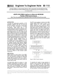
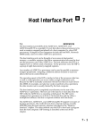
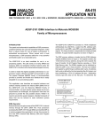
1
DMA Ports
11.1
11
OVERVIEW
The ADSP-2181 supports several DMA interfacing features:
• Byte Memory & Byte Memory DMA (BDMA): this memory space can
address up to 4M bytes. The byte memory interface supports booting
from and runtime access to inexpensive 8-bit memories. The BDMA
feature lets you define the number of memory locations the ADSP-2181
will transfer to/from internal memory in the background while
continuing foreground processing.
• Internal Direct Memory Access (IDMA) Port: this parallel port
supports booting from and runtime access to host systems (for example,
PC Bus Interface ASICs). The DMA feature of this port lets you transfer
data to/from internal memory in the background while continuing
foreground processing.
These DMA transfers are accomplished internally by “cycle stealing,” in
the same way as serial port autobuffering. This means that the ADSP-2181
uses internal bus cycles to transfer the data to and from memory. The
stolen cycles will only occur at instruction cycle boundaries, i.e. not
between cycles of a multiple-cycle instruction. See “IACK Acknowledge &
DMA Cycle Stealing” at the end of this chapter for additional details.
The ADSP-2181 uses a half-instruction-rate clock input from which it
generates a full-instruction-rate internal clock. For example, from a 16.67
MHz clock input (CLKIN) the ADSP-2181 generates a 33.33 MHz
instruction rate clock. All timing diagrams for the processor use the fullinstruction-rate output clock (CLKOUT) as a reference.
Figure 11.1 shows an ADSP-2181 system and the interfaces to byte
memory space and the IDMA port.
11 – 1
11 DMA Ports
ADSP-2181
1/2x CLOCK
or
CRYSTAL
CLKIN
XTAL
14
ADDR13-0
A13-0
D 23-16
FL0-2
PF0-7
24
D15-8
DATA23-0
A0-A21
BYTE
MEMORY
DATA
IRQ2
IRQE
IRQL0
IRQL1
CS
BMS
A 10-0
ADDR
D 23-8
SPORT 1
SERIAL
DEVICE
2048 Locations
IOMS
IDMA PORT
IRD
IWR
IS
IAL
IACK
16
IAD15-0
CS
A 13-0
ADDR
SPORT 0
SCLK0
RFS0
TFS0
DT0
DR0
SERIAL
DEVICE
SYSTEM
INTERFACE
or
µCONTROLLER
DATA
SCLK1
RFS1 or IRQ0
TFS1 or IRQ1
DT1 or FO
DR1 or FI
I/O SPACE
(PERIPHERALS)
D23-0
PMS
DMS
CMS
DATA
OVERLAY
MEMORY
Two 8K
PM Segments
Two 8K
DM Segments
BR
BG
BGH
PWD
PWDACK
Figure 11.1 ADSP-2181 System
11.2
BDMA PORT
The ADSP-2181’s byte memory space is 8 bits wide and can address up to
4M bytes of program code or data. This memory space takes the place of
the boot memory space found on other ADSP-2100 family processors.
Unlike boot memory space, byte memory has read/write access through
the ADSP-2181’s BDMA port.
Each read/write to byte memory consists of data (on data bus lines 15:8)
and address (on address bus lines 13:0 plus data lines 23:16). The 22-bit
byte memory address lets you access up to 4M bytes of ROM or RAM.
11 – 2
DMA Ports 11
Byte memory space consists of 256 pages, each containing 16K x 8-bit wide
locations. This memory can be written and read in four different formats:
24-bit, 16-bit, 8-bit MSB alignment, and 8-bit LSB alignment.
To use byte memory for purposes other that boot loading, for example
runtime access to bulk data storage, you must know the page (BMPAGE)
that the code/data is stored on, the number of words (BWCOUNT) to read
from that page, and the word format (BTYPE) of the data. Use the following
procedure to prepare a runtime-accessible byte memory EPROM:
• Develop the data/code to be accessed at runtime
• Use the ADSP-2100 Family PROM Splitter utility to split the file into
single page (or smaller) 16K x 8-bit-wide segments
• Program these pages into your EPROM, noting the offset (page number)
of each
• Use these page numbers when doing BDMA accesses
Note: For more information on the ADSP-2100 Family Development
Software Tools, see the ADSP-2100 Family Assembler Tools & Simulator Manual
and current software release note.
When using BDMA for non-boot-loading transfers, a BDMA transfer begins when
data is written to the BWCOUNT register and a BDMA interrupt is issued when the
transfer is complete.
The following restrictions apply to BDMA transfers:
• The source or target of BDMA transfer is always internal program or data
memory. The contents of the PMOVLAY and DMOVLAY registers do not
influence BDMA source (or target selection).
• Do not access the BEAD or BIAD registers during BDMA transfers.
• Other external memory accesses (PM overlay, DM overlay, or I/O space)
take precedence over BDMA port accesses. These accesses cannot occur at
the same time because they also use the processor’s external bus.
• Do not enter powerdown mode with the BDMA port active. For
information on powerdown restrictions on BDMA port access, see the
System Interface chapter of this manual.
11 – 3
11 DMA Ports
11.2.1
BDMA Port Functional Description
The BDMA Port lets you load (and store) program instructions and data
from (and to) byte memory with very low processor overhead. While the
ADSP-2181 is executing program instructions, the BDMA port reads (or
writes) code or data from (or to) byte memory—stealing one ADSP-2181
cycle per word when it needs to write to (or read from) internal memory.
You can calculate BDMA transfer time from the formula:
Number
of PM
or DM
Words
Number
of Bytes
per Word
Number
of Added
Waitstates
per Byte
+
1
Cycle
for
Transfer
+
1
Cycle for
Internal
+
RD/WR
Hold
Offs
If, for example, you wanted to transfer 100 24-bit program memory words
through the BDMA port, assuming five waitstates and no hold offs, the
operation would take 1900 cycles. This is shown in the following equation:
100
PM
Words
3
Bytes
per
Word
5
Added
Waitstates
per Byte
+
1
Cycle
for
Transfer
+
1
Cycle for
Internal
RD/WR
+
0
Hold
Offs
Hold offs for DMA transfers are defined in the section “DMA Cycle
Stealing, DMA Hold Offs, and IACK Acknowledge” at the end of this
chapter.
11.2.2
BDMA Control Registers
A set of memory-mapped registers are used to setup and control transfers
through the BDMA port. Figures 11.2 through 11.6 show these registers.
The BDMA Internal Address Register (BIAD) lets you set the 14-bit
internal memory starting address for a BDMA transfer. The BDMA
External Address Register (BEAD) lets you set the 14-bit external memory
starting address for a BDMA transfer.
11 – 4
DMA Ports 11
BDMA Internal Address
15
14
13
12
11
10
9
8
7
6
5
4
3
2
1
0
0
0
0
0
0
0
0
0
0
0
0
0
0
0
0
0
DM(0x3FE1)
BIAD
Figure 11.2 BDMA Internal Address Register
BDMA External Address
15
14
13
12
11
10
9
8
7
6
5
4
3
2
1
0
0
0
0
0
0
0
0
0
0
0
0
0
0
0
0
0
DM(0x3FE2)
BEAD
Figure 11.3 BDMA External Address Register
11 – 5
11 DMA Ports
BDMA Control
15
14
13
12
11
10
9
8
7
6
5
4
3
2
1
0
0
0
0
0
0
0
0
0
0
0
0
0
1
0
0
0
DM(0x3FE3)
BTYPE (see table)
BMPAGE
BDIR
0 = load from BM
1 = store to BM
BTYPE
00
01
10
11
Internal Memory Space PM DM
DM DM
Word Size
24
16
8
8
Alignment
full
full
MSB LSB
word word
Figure 11.4 BDMA Control Register
The BDMA Control Register lets you set:
•
•
•
•
The BDMA Transfer Type (BTYPE)
The BDMA Direction (BDIR)
The BDMA Context Reset (BCR)
The BDMA Page (BMPAGE)
BTYPE can be:
00
01
10
10
24-bit Program Memory Words
16-bit Data Memory
8-bit bytes for Data Memory, MSB alignment
8-bit bytes for Data Memory, LSB alignment
BDIR can be:
0
1
11 – 6
from Byte Memory
to Byte Memory
BCR
0 = run during BDMA
1 = halt during BDMA,
context reset when done
DMA Ports 11
BCR can be set to:
0
1
Allow program execution during BDMA
Inhibit program execution during BDMA transfers and cause a
context reset after transfer is complete
BMPAGE lets you select the starting page for BDMA transfer.
Note: Rebooting with BDMA Context Reset (BCR=1) is similar to a
Powerup Context Reset. For more details on processor states during reset
and reboot, see the System Interface chapter of this manual.
The BWCOUNT register lets you start a BDMA transfer by writing the
number of words for the transfer to this register. The count automatically
decrements as the transfer proceeds. When the count is zero (i.e. transfer
complete), the processor issues a BDMA interrupt. When MMAP and
BMODE are set to zero on boot, a value of 32 (decimal) is written to this
register directing the ADSP-2181 to load the first 32 locations of its
internal program memory.
Two useful control techniques using this register are:
• Poll the BWCOUNT register to determine when the DMA transfer is
complete (BWCOUNT=0), instead of waiting for the BDMA interrupt.
• Abort the DMA operation by writing a 1 to the BWCOUNT register and
poll to determine when the transfer is complete (BWCOUNT=0),
instead of waiting for the BDMA interrupt. (Note that the DMA transfer
is aborted, and cannot be resumed later.)
BMWAIT consists of bits 12, 13, and 14 of the Programmable Flag &
Composite Select Control Register. BMWAIT lets you select 0-7 waitstates
(each equal to a single instruction cycle) to apply to each byte memory
access. BMWAIT is set to 7 after a reboot.
11 – 7
11 DMA Ports
BDMA Word Count (MMAP=0 and BMODE=0)
15
14
13
12
11
10
9
8
7
6
5
4
3
2
0
0
0
0
0
0
0
0
0
0
1
0
0
0
1
0
0
0
DM(0x3FE4)
BWCOUNT
or
BDMA Word Count (MMAP=1 or BMODE=1)
15
14
13
12
11
10
9
8
7
6
5
4
3
2
0
0
0
0
0
0
0
0
0
0
0
0
0
0
1
0
0
0
DM(0x3FE4)
BWCOUNT
Figure 11.5 BDMA Word Count Register
Programmable Flag & Composite Select Control
15
14
13
12
0
1
1
1
BMWAIT
CMSSEL
1 = Enable CMS
0 = Disable CMS
11
10
9
8
7
6
5
4
3
2
1
0
0
0
0
0
0
0
0
0
1
0
1
1
IOM
BM
DM
PM
DM(0x3FE6)
PFTYPE
1 = Output
0 = Input
Figure 11.6 BMWAIT Field (in Programmable Flag & Composite Select Control Register)
11 – 8
DMA Ports 11
11.2.3
Byte Memory Word Formats
In your byte memory ROM or RAM, data is stored by the ADSP-21xx PROM
Splitter according to the data format you select: 24-bit program memory
words, 16-bit data memory words, 8-bit data memory bytes with MSBalignment, or 8-bit data memory bytes with LSB-alignment. The byte order
for 24-bit program memory words and 16-bit data memory words stored in
byte memory is most-significant-byte in the lower address. Table 11.1 shows
an example of byte memory storage of all four code/data formats.
Note: When transferring either of the data memory byte formats, the unused
byte of data memory is zero-filled.
BTYPE
00
Internal
Memory
Address
PM(0x0000)
Internal
Memory
Contents
0xABCDEF
00
PM(0x0001)
0x123456
01
DM(0x0000)
0x9876
01
DM(0x0001)
0x3456
10
10
11
11
DM(0x0002)
DM(0x0003)
DM(0x0004)
DM(0x0005)
0x9800
0x7600
0x0034
0x0056
Byte Memory
Address
(page 0x00)
BM(0x0000)
BM(0x0001)
BM(0x0002)
BM(0x0003)
BM(0x0004)
BM(0x0005)
BM(0x0006)
BM(0x0007)
BM(0x0008)
BM(0x0009)
BM(0x000A)
BM(0x000B)
BM(0x000C)
BM(0x000D)
Byte
Memory
Contents
0xAB
0xCD
0xEF
0x12
0x34
0x56
0x98
0x76
0x34
0x56
0x98
0x76
0x34
0x56
Table 11.1 Byte Memory Storage Formats
11.2.4
BDMA Booting
The entire on-chip program memory of the ADSP-2181, or any portion of it,
can be loaded from an external source using a byte memory booting
sequence. Booting from byte memory is one of two methods available for
automatic booting after a reset.
Table 11.2 shows how to select the post-reset booting method using the
ADSP-2181’s MMAP and BMODE pins.
11 – 9
11 DMA Ports
MMAP
Pin
0
BMODE
Pin
0
0
1
1
–
Booting
Method
Boot through BDMA Port. Boot sequence loads the
first 32 program memory words from the byte
memory space. After all 32 words are loaded,
program execution begins at internal address
PM(0x0000) with a BDMA interrupt pending.
Boot through IDMA Port. Boot sequence holds off
execution while the host processor loads Program
Memory using writes through the IDMA Port.
Program execution begins when internal address
PM(0x0000) is loaded.
No Booting. Boot sequence does not load memory or
hold off execution. Program execution starts at
external address PM(0x0000). The PMOVLAY
register must be cleared (to zero).
Table 11.2 Selecting The ADSP-2181 Boot Method
The ADSP-2181 uses a BDMA boot sequence after reset when the BMODE
and MMAP pins are held low. The BDMA port is initialized for booting as
follows:
• BWCOUNT is set to 32
• BDIR, BMPAGE, BEAD, BIAD, and BTYPE are set to zero
• BCR is set to 1
• BMWAIT is set to 7
These initializations set the BDMA port to load 32 words (BWCOUNT)—
from (BDIR)—byte memory page zero (BMPAGE)—byte memory address
zero (BEAD) —to internal Program Memory address zero (BIAD)—using
24-bit program memory word format (BTYPE). The BDMA context reset bit
(BCR) set to 1 inhibits program execution during BDMA transfer and
causes execution to begin at address PM(0x0000) after the transfer. The
number of waitstates (BMWAIT) for BDMA access is set to the maximum
of 7. After the boot sequence is complete (32 words transferred), program
execution begins at internal PM address 0x0000.
The ADSP-2100 Family PROM Splitter utility provides a boot loader
option for ADSP-2181 based designs; see “Development Software Features
for BDMA Booting” below.
11 – 10
DMA Ports 11
If you are developing your own boot-loading software for the ADSP-2181,
however, you should note that the BDMA Context Reset bit (BCR) is set to
1 (inhibiting program execution during BDMA transfer) and a BDMA
interrupt is pending (signalling the first 32 word were sent) after the boot
sequence is complete. Your program will have to process the interrupt (if
you unmask the BDMA interrupt with the IMASK register) or clear the
interrupt (with the IFC register).
In an alternate method, using the BDMA interrupt without context clear, a
loader program could suspend program execution with the IDLE
instruction while BDMA boot loading. If the loader sets the PM boot-load
parameters, enables only the BDMA interrupt in the IMASK register, and
then executes an IDLE instruction—the IDLE instruction suspends
program execution until the BDMA interrupt occurs. At that point all of
program memory is loaded.
11.2.4.1 Development Software Features for BDMA Booting
The ADSP-21xx PROM Splitter utility lets you create BDMA bootloader programs for ADSP-2181-based designs. This provides a
low overhead method for BDMA boot-loading your program. The
boot loader program adds memory loader code to your executable
program. The PROM Splitter generates loader code that initializes
up to 6 pages of program memory and 4 pages of data memory,
where each page is 16k bytes in size. Typically, the code generated
by the PROM Splitter is burned into an EPROM and used as the
ADSP-2181’s Byte Memory space.
When the MMAP and BMODE pins equal 0, the ADSP-2181 will
load the first 32 program memory words from the Byte memory
space and then begin execution. The loader routine is in those first
32 words; it continues to load from the Byte Port until your whole
program is loaded.
Refer to the ADSP-2100 Family Assembler Tools & Simulator Manual
as well as the software release note for complete information on
the PROM Splitter features.
11 – 11
11 DMA Ports
11.3
IDMA PORT
The IDMA Port of the ADSP-2181 is a parallel I/O port that lets the
processor’s internal memory be read or written by a host system. The IDMA
Port architecture eases host bus interface design.
Think of the IDMA port as a gateway to all internal memory locations on the
DSP (except for the processor’s memory-mapped control registers). The
IDMA Port has a 16-bit multiplexed address and data bus that supports
access to both 16-bit Data Memory and 24-bit Program Memory. IDMA Port
read/write access is completely asynchronous and a host can access the
DSP’s internal memory while the ADSP-2181 is operating at full speed.
Unlike the Host Interface Port (HIP) of the ADSP-2171 and ADSP-2111, the
IDMA port does not require any ADSP-2181 processor intervention to
maintain data flow. The host system can access ADSP-2181 internal memory
directly, without going through a set of mailbox registers. Direct access to
DSP memory increases throughput for block data transfers. Through the
IDMA port, internal memory accesses can be performed with an overhead of
one DSP processor cycle per word.
The ADSP-2181 supports boot loading through the IDMA port, through the
BDMA port, or from an external Program Memory Overlay. The BMODE
and MMAP pins select the DSP’s boot mode and memory map. Setting
BMODE=1 and MMAP=0 directs the ADSP-2181 to boot through the IDMA
Port. For information on IDMA booting, see “Boot Loading Through The
IDMA Port” at the end of this chapter.
Note: The IDMA port cannot be used to read or write the ADSP-2181’s
memory-mapped control registers. See “Modifying Control Registers for
IDMA.”
11.3.1
IDMA Port Pin Summary
The IDMA Port pins are shown below in Table 11.3.
Pin Name(s)
IRD
IWR
IS
IAL
IAD0-15
IACK
Input/
Output
I
I
I
I
I/O
O
Table 11.3 IDMA Port Pins
11 – 12
Function
IDMA Port Read Strobe
IDMA Port Write Strobe
IDMA Port Select
IDMA Port Address Latch Enable
IDMA Port Address/Data Bus
IDMA Port Access Ready Acknowledge*
* After reset, IACK is asserted (low). It stays low until an IDMA transfer is initiated. After
each IDMA operation is completed, IACK will again be low.
DMA Ports 11
Four IDMA port inputs control when the port is selected (IS) for read
(IRD), write (IWR), or address latch (IAL) operations on its address/data
bus (IAD0-15). The IDMA Port Select (IS) line acts as a chip select for all
IDMA operations.
Asserting the IDMA Port Select (IS) and address latch enable (IAL) directs
the ADSP-2181 to write the address on the IAD0-15 bus into the IDMA
Control Register. This register, shown in Figure 11.7, is memory-mapped
at address DM(0x3FE0). Note that the latched address (IDMAA) cannot be
read back by the host.
IDMA Control Register
15
14
13
12
11
10
9
8
7
6
5
4
3
2
1
0
DM(0x3FE0)
IDMAD
Destination memory type:
0=PM
1=DM
IDMAA
Starting address
Figure 11.7 IDMA Control Register
Asserting the IDMA Port Select (IS) and Read strobe (IRD) inputs directs the
ADSP-2181 to output the contents of the memory location pointed to by the
IDMA Control register onto the IDMA data bus.
Asserting the IDMA Port Select (IS) and Write strobe (IWR) inputs directs the
ADSP-2181 to write the input from the IDMA data bus to the address pointed
to by the IDMA register.
When reading/writing to Data Memory, the IDMA data bus pins make up a
16-bit Data Memory word. When reading/writing to Program Memory, the
upper 16 bits of the 24-bit Program Memory word are sent first on the IDMA
data bus pins. On the next IDMA Port read/write, the lowest 8 bits of the
Program Memory word are sent on bits 0-7 of the IDMA data bus. For reads,
the ADSP-2181 sets data bus lines 8-15 to 0; for writes, the ADSP-2181 ignores
bits 8-15 from the host.
The IDMA Port Access Acknowledge (IACK) line identifies completion of
data reads/write operations. It also acts as a busy signal for the IDMA Port.
External devices must wait for this signal to go low before modifying IDMA
Control register or starting the next read/write operation.
11 – 13
11 DMA Ports
11.3.2
IDMA Port Functional Description
The IDMA Port lets a host system directly access internal ADSP-2181
memory locations (but not the memory-mapped control registers). Figure
11.8 shows a flow chart of the most general case for IDMA transfers.
In the case shown in Figure 11.8, the host system starts an IDMA transfer
by checking the state of the IACK line to determine port status (ready/
busy). When the IDMA port is ready, the host directs the ADSP-2181 (with
the IS and IAL lines) to latch the IDMA internal memory address from the
IDMA address/data bus to the IDMA Control Register. (Note that the
latched address cannot be read back by the host.)
Next, the host (using the IS and IRD or IS and IWR lines) begins reading
(or writing) the DSP’s internal memory until done. With each IDMA read
or write operation, the the ADSP-2181 automatically increments the IDMA
internal memory address. Note that the ADSP-2181 continues program
execution throughout the IDMA transfer operation, except during the
“stolen” cycle used to do the memory access.
The case shown in Figure 11.8 is not the only way to use the IDMA port.
Some variations on this scheme include:
• After completing an IDMA port read/write operation, the host could
change the IDMA internal memory address and start a new operation
from a different starting address.
• After latching an IDMA internal memory address, the host could stop
the operation and come back at a later time to proceed with the read/
write operation. The IDMA starting memory address remains in the
IDMA Control Register until the host or DSP changes it.
• The ADSP-2181 can also read and write the IDMA Control Register as
part of your program. This means that the host could just control read/
write operations and let the ADSP-2181 control the IDMA starting
memory address.
• Using the IDMA short read cycle (which does not wait for the data-ready
assertion of the IACK signal), you could set up a single-location data
buffer for IDMA read transfers. For information on how this data buffer
would work, see “IDMA Port Short Read Cycle” below.
• For ADSP-2181 applications with a host processor or host ASIC that
does not use a data-ready or write-complete acknowledge, use the
IDMA short read/write cycles.
11 – 14
DMA Ports 11
Host starts IDMA transfer.
Host checks IACK control line to
see if the DSP is "Busy".
Host uses IS and IAL control lines to
latch the DMA starting address
(IDMAA) and PM/DM selection into the
DSP's IDMA Control Register. The
DSP also can set the starting address
and memory destination.
Continue
More?
Host uses IS and IRD (or IWR) to
read (or write) DSP internal memory
(PM or DM).
Host checks IACK line to see if the
DSP has completed the previous
IDMA operation.
Done?
Host ends IDMA transfer.
Figure 11.8 General IDMA Transfer Flow Chart
There are some restrictions on IDMA operations. These hardware/
software design restrictions include:
• If your design has both the host and ADSP-2181 writing to the IDMA
Control Register, do not let both write to this register at the same time;
the results of this are indeterminate.
• Host reads of internal Program Memory take two IDMA reads (for a 24bit word through a 16-bit port). If an IDMA address latch cycle or a
ADSP-2181 write to the IDMA Control Register occurs after the first
Program Memory read cycle, the IDMA port “loses” the second half of
the 24-bit Program Memory word. The next IDMA read or write uses
the address selected by the new contents of the IDMA Control Register.
Note that writing to the IDMA Control Register after the first half of a
Program Memory IDMA read lets you read just 16-bit data from
Program Memory.
11 – 15
11 DMA Ports
• Host writes to internal Program Memory take two IDMA writes (for a
24-bit word through a 16-bit port). If an IDMA address latch cycle or a
ADSP-2181 write to the IDMA Control Register occurs after a first
Program Memory write cycle, the IDMA port “loses” the Program
Memory word without changing the contents of memory. The next
IDMA read or write accesses the address selected by the new contents
of the IDMA Control Register.
• Host memory accesses through the IDMA port that occur while the
ADSP-2181 is in powerdown have some restrictions. For information on
powerdown restrictions on IDMA port transfers, see the System Interface
chapter of this manual.
11.3.3
Modifying Control Registers for IDMA
The ADSP-2181’s memory-mapped control registers are protected from
DMA transfers to prevent accidental corruption. You may want the host
processor to read and write these registers, however, in order to
determine the ADSP-2181’s configuration and then change it.
To read the memory-mapped control registers, you must first transfer the
contents of these locations to another area of internal RAM. The following
code segment shows a loop that performs this task:
.const NUM_REG=32;
.var/dm/ram temp_array[NUM_REG];
transfer:
i0=^temp_array;
l0=0;
i1=0x3fe0;
l1=0;
m1=1;
cntr=NUM_REG;
do transfer until ce;
ax0=dm(i1,m1);
dm(i0,m1)=ax0;
To have the host write to the memory-mapped control registers, you must
first load the values to a temporary buffer (through the IDMA port) and
then signal the ADSP-2181 to transfer the contents of the temporary buffer
to the memory-mapped control registers. This transfer is performed in a
similar manner as the code shown above. You should set up some form of
signalling between the host and the ADSP-2181, either interrupts, flag
I/O, or a mailbox register. This will provide a mechanism for the host to
tell the DSP when to perform an operation and vice versa.
11 – 16
DMA Ports 11
11.3.4
IDMA Timing
From the host system interface point of view, there are three IDMA port
operations with critical timing parameters. These operations are:
• latching the IDMA internal memory address,
• reading from the IDMA port, and
• writing to the IDMA port.
The following sections cover the timing details of each of these operations.
11.3.4.1 Address Latch Cycle
The host writes the DMA starting address and destination memory type
(DM or PM) using the IDMA address latch cycle. The address latch cycle,
shown in Figure 11.9, consists of the following steps:
1. Host ensures that IACK line is low.
2. Host asserts IAL and IS, directing the ADSP-2181 to latch the IDMA
starting address from the IAD15-0 address/data bus into the IDMA
Control Register.
3. Host drives the starting address (bits 0-13) and destination memory
type (bit 14) onto the IAD15-0 bus. (Bit 15 must be a 0.)
Note that IRD and IWR remain high (inactive) throughout the latch
operation.
IACK
IAL
IS
IAD15-0
ADDRESS
Figure 11.9 IDMA Address Latch Cycle Timing
11 – 17
11 DMA Ports
Note: The IDMA starting address and destination memory type is available to
the host and to the ADSP-2181 in the IDMA Control Register. For Data Memory
accesses, the ADSP-2181 increments the address automatically after each IDMA
read or write transfer (16-bit word). For Program Memory accesses, the
ADSP-2181 increments the address automatically after each pair of IDMA read
or write transfers (24-bit word).
Warning: Both the ADSP-2181 and the host can specify the starting address by
writing to the IDMA Control Register. Do not let the ADSP-2181 access the
IDMA Control Register while it is being written by the host; this operation will
have an indeterminate result.
11.3.4.2 Long Read Cycle
The host reads the contents of an ADSP-2181 internal memory location using
the IDMA port long read cycle. The read cycle, shown in Figure 11.10, consists
of the following steps:
1. Host ensures that IACK line is low.
2. Host asserts IRD and IS (low), causing the ADSP-2181 to put the contents of
the location pointed to by the IDMA address on the IAD15-0 address/data
bus.
3. ADSP-2181 deasserts IACK line, indicating the requested data is being
fetched. When the ADSP-2181 asserts the IACK line, the requested data is
driven on the IAD address/data bus.
4. Host detects the IACK line is now low and reads the data (READ DATA)
from the IAD15-0 address/data bus. After reading the data, the host
deasserts IRD and IS.
Note that IAL is low (inactive) and IWR is high (inactive) throughout the read
operation.
IDMA memory accesses “steal” one processor cycle, but may only occur on
instruction cycle boundaries. The best-case response for a 16-bit Data Memory
read or the first 16 bits of a Program Memory read is 2.5 processor cycles; worst
case is 3.5 cycles. One cycle is for synchronization, one is for reading the
memory internally, and one-half cycle is for IACK setup time. A second cycle of
synchronization may be required. Thus the best-case and worst-case response
times are determined as follows:
Best Case:
1 cycle (sync) + 1 cycle (internal memory read) + 0.5 cycle (IACK setup) = 2.5 cycles
Worst Case: 1 cycle (sync) + 1 cycle (sync) + 1 cycle (internal memory read) + 0.5 cycle (IACK setup) = 3.5 cycles
11 – 18
DMA Ports 11
IACK
IS
IRD
IAD15-0
PREVIOUS
DATA
READ
DATA
Figure 11.10 IDMA Long Read Cycle Timing
In the case of a Program Memory operation, the second IDMA port read
cycle for a given internal 24-bit word does not require an internal memory
access, does not wait for an instruction cycle boundary, and takes 1.5 or
2.5 cycles.
The best- and worst-case response times given above assume no system hold offs.
Hold offs for DMA transfers are defined in the section “DMA Cycle
Stealing, DMA Hold Offs, and IACK Acknowledge” at the end of this
chapter.
Warning: If an IDMA address latch cycle or an ADSP-2181 write to the
IDMA Control Register occurs after a first Program Memory read cycle (16
bits), the IDMA port will lose the second half of the Program Memory
word. The ADSP-2181 treats the next IDMA access as the first operation
for the new IDMA address and destination.
11 – 19
11 DMA Ports
11.3.4.3 Short Read Cycle
The host reads the contents of a ADSP-2181 internal memory location using
the IDMA short read cycle. The read cycle, shown in Figure 11.11, consists
of the following steps:
1. Host ensures that IACK line is low.
2. Host asserts IRD and IS (low), directing the ADSP-2181 to put the
contents of the location pointed to by the target IDMA address on the
IAD15-0 address/data bus.
3. ADSP-2181 deasserts IACK line, indicating the requested data is being
fetched.
4. Host detects the IACK line is now high and reads the data (PREVIOUS
DATA) from the IAD15-0 address/data bus, before the requested data
(READ DATA) is driven on the IAD address/data bus—not waiting for
the ADSP-2181 to assert the IACK line. After reading the data, the host
deasserts IRD and IS.
The host must do an initial “dummy” read, to make the ADSP-2181 put the
first data word (PREVIOUS DATA) on the IAD15-0 bus.
Note that IAL is low (inactive) and IWR is high (inactive) throughout the
read operation.
The IDMA Short Read and Long Read cycles provide different alternatives
for implementing your DMA transfers. Short reads are useful for hosts that
can handle the faster timing of these accesses, while long reads allow
slower hosts more time.
The IDMA short read cycle also serves as a single-location data buffer. If
you are using the ADSP-2181 in a multiprocessing environment, using this
buffer is one way to avoid tying up the IAD bus (waiting for IACK signal).
Warning: If an IDMA address latch cycle or a ADSP-2181 write to the
IDMA Control register occurs after a first Program Memory read cycle, the
IDMA port will lose the second half of the Program Memory word. The
ADSP-2181 treats the next host data on the IAD address/data bus as the
new contents of the IDMA Control Register.
11 – 20
DMA Ports 11
IACK
IS
IRD
IAD15-0
PREVIOUS
DATA
Figure 11.11 IDMA Short Read Cycle Timing
11.3.4.4 Long Write Cycle
The host writes the contents of an internal memory location using the
IDMA long write cycle. The write cycle, shown in Figure 11.12, consists of
the following steps:
1. Host ensures that IACK line is low.
2. Host asserts IWR and IS (low), directing the ADSP-2181 to write the
data on the IAD15-0 address/data bus to the location pointed to by the
target IDMA address .
3. ADSP-2181 deasserts the IACK line, indicating it recognizes the IDMA
write operation.
4. Host drives the data on the IAD address/data bus.
5. ADSP-2181 asserts IACK line, indicating it latched the data on the
IAD15-0 address/data bus.
6. Host recognizes the IACK line is now low, stops driving the data on
the IDMA address/data bus and deasserts IWR and IS (ending the
IDMA Long Write Cycle).
Note that IAL is low (inactive) and IRD is high (inactive) throughout the
write operation.
11 – 21
11 DMA Ports
IACK
IS
IWR
IAD15-0
DATA
Figure 11.12 IDMA Long Write Cycle Timing
Note: IDMA port writes to Program Memory require two IDMA port
write cycles to write a word to ADSP-2181 internal Program Memory. The
ADSP-2181 acknowledges the IDMA port write of the first 16 bits (MSBs
of PM word) as they are written to a temporary holding latch, not waiting
for an instruction cycle boundary. The ADSP-2181 does not assert the
IACK line after the second Program Memory write (or all Data Memory
writes) until the internal memory write is complete and the IDMA port is
ready for another transaction.
Warning: Host IDMA write accesses to internal Program Memory take
two IDMA port writes (24-bit word through a 16-bit port). If an IDMA
address latch cycle or a ADSP-2181 write to the IDMA Control register
occurs after a first program memory write cycle, the IDMA port “loses”
the Program Memory word without changing the contents of ADSP-2181
internal memory. The next IDMA read or write uses the address selected
by the new contents of the IDMA Control register.
11 – 22
DMA Ports 11
11.3.4.5 Short Write Cycle
The host writes the contents of a ADSP-2181 internal memory location using the
IDMA short write cycle. The write cycle, shown in Figure 11.13, consists of the
following steps:
1. Host ensures that IACK line is low.
2. Host asserts IWR and IS (low), directing the ADSP-2181 to write the data on
the IAD15-0 address/data bus to the location pointed to by the target IDMA
address .
3. ADSP-2181 deasserts IACK line (high), indicating it recognizes the IDMA
write operation.
4. Host drives the data on the IAD address/data bus.
5. Host deasserts IWR and IS after meeting the short write timing requirements
(ending the short write cycle).
6. ADSP-2181 detects IWR and IS have gone high, then latches the data on the
IAD address/data bus.
7. Host stops driving the data on the IAD15-0 address/data bus after meeting
the short write timing requirements.
Note that IAL is low (inactive) and IRD is high (inactive) throughout the write
operation.
IACK
IS
IWR
IAD15-0
DATA
Figure 11.13 IDMA Short Write Cycle Timing
11 – 23
11 DMA Ports
Note: IDMA port writes to Program Memory require two IDMA port
write cycles to write a word to ADSP-2181 internal Program Memory. The
ADSP-2181 acknowledges the IDMA port write of the first 16 bits (MSBs
of PM word) as they are written to a temporary holding latch, not waiting
for an instruction cycle boundary. The ADSP-2181 does not assert the
IACK line after the second Program Memory write (or all Data Memory
writes) until the internal memory write is complete and the IDMA port is
ready for another transaction.
Warning: If an IDMA address latch cycle or a ADSP-2181 write to the
IDMA Control register occur after a first Program Memory write cycle, the
IDMA port will lose the first half of the Program Memory word. The next
Program Memory write will be considered the first half of a Program
Memory write pair.
There are two features that differentiate between the IDMA Port long
write and short write. The long write supports hosts (processors or ASICs)
that allow a data-written acknowledge. If your host needs the ADSP-2181
to signal that it has written the data, use the IDMA long read cycle.
The short write lets your host hold data on the bus just until it is latched
and then release the bus. If you are using the ADSP-2181 in a
multiprocessing environment, using the short write is one way to avoid
tying up the IAD15-0 data bus (waiting for IACK signal). Short writes are
also useful for hosts that can handle the short write timing, but can’t
extend the accesses with IACK (when holdoffs occur).
11.3.5
Boot Loading Through The IDMA Port
The ADSP-2181 supports boot loading through the IDMA port. To boot
through the IDMA Port, use the following steps:
Reset the processor (assert RESET).
Set MMAP=0 and BMODE=1. These pin settings select IDMA booting.
Deassert RESET.
Load ADSP-2181 internal memory through the IDMA port. Program
execution is held off until you write to Program Memory address zero,
PM(0x0000). The ADSP-2181 responds to IDMA control signals (IAL,
IS, IWR, and IRD) and provides acknowledge (IACK) in the same
manner as during non-booting IDMA transfers.
• Write to PM(0x0000) to begin program execution.
•
•
•
•
Warning: Make certain to load all of the necessary memory locations with
the proper data before writing to PM(0x0000).
11 – 24
DMA Ports 11
11.3.6
DMA Cycle Stealing, DMA Hold Offs, and IACK Acknowledge
The IACK signal is generated by the ADSP-2181 to signal that it is safe to
read or write through the IDMA port. After reset, IACK is asserted (low).
It stays low until an IDMA transfer is initiated. After each IDMA
operation is completed, IACK will again be low.
In order for IACK to be asserted (low) during the IDMA operation, the
IDMA port must have completed the internal memory access by either
writing data to memory or reading data from memory. The IDMA port
must “steal” a processor cycle to do this. In order to steal a processor
cycle, the IDMA port must wait for an instruction completion boundary.
Thus if IACK is not asserted, it is not safe for the host to access the IDMA port.
In most cases, there is an instruction boundary on every clock cycle
(CLKOUT period) and the IDMA port can complete its transfer in a given
period of time. There are, however, some instances where either the
ADSP-2181 does not complete an instruction in one clock cycle or the
IDMA port cannot access memory. These are DMA hold offs:
• Bus Request – If the ADSP-2181 is being held in Bus Request when it
attempts an external access (DM overlay, PM overlay, or I/O memory
space), or if it is not in GO mode, processor execution stops in the
middle of the cycle and no instruction boundary is encountered.
Therefore, the IDMA port cannot complete its internal memory access
and IACK will be held off.
• External Access with Wait State(s) – If the ADSP-2181 is performing a
wait-stated external access (DM overlay, PM overlay, or I/O memory
space), then the instruction cycle will not complete until the access has
completed; the IDMA port cannot steal a cycle, and IACK will be held
off.
• Multiple External Accesses – If the ADSP-2181 is executing a
multifunction instruction where more than one of the required elements
(PM instruction fetch, PM data access, or DM data access) resides
externally, it will require more than one cycle to complete the
instruction and IACK will be held off. Likewise, if the ADSP-2181 is
executing an instruction from external PM that initiates an I/O memory
space access, IACK will be held off until the cycle completes.
• IDLE n (clock-reducing IDLE instruction) – Because this instruction
slows down the effective cycle time of the ADSP-2181, IACK may be
delayed.
11 – 25
11 DMA Ports
• SPORT Autobuffering to External Memory with Waitstated Access –
When one of the processor’s serial ports needs to access external
memory for autobuffering and the external access takes more than one
cycle, the IDMA transfer will be held off.
• EZ-ICE Emulation – When the EZ-ICE emulator is controlling your
ADSP-2181 target system, IDMA transfers may be held off for periods
of time.
Using the IACK signal simplifies your system design by allowing you to
ignore hold-off conditions. If you always wait for IACK to assert before
accessing the IDMA port, the DMA transfers will always operate properly.
You can ignore IACK , however, if you are sure that no hold-offs occur in your
system or if your IDMA accesses are longer than any hold-offs. To be sure of
this, you must carefully analyze all possible hold-off conditions of your
system.
11 – 26