1
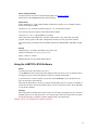
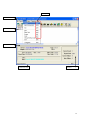
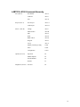
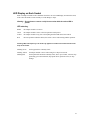
LABTOOL-S100 Serial Flash Programmer User's Manual Date: 2012/3/22 Revision: 1.00.00 Copyright Notice This document is copyrighted, 2012 by Advantech Equipment Corp., Ltd. All rights are reserved. Advantech Equipment Corp., Ltd., reserves the right to make improvements to the products described in this manual at any time without notice. No part of this manual may be reproduced, copied, translated or transmitted in any form or by any means without the prior written permission of Advantech Equipment Corp., Ltd. Information provided in this manual is intended to be accurate and reliable. However, Advantech Equipment Corp., Ltd. assumes no responsibility for its use, nor for any infringements upon the rights of third parties which may result from its use. Acknowledgments IBM, PC AT and VGA are trademarks of International Business Machines Corporation. MS-Windows are trademarks of Microsoft Corporation. 2 How to use this manual Thank you for purchasing the LABTOOL-S100 Serial Flash Programmer. We designed this manual to help you quickly and easily set up and use your LABTOOL-S100. You can use the manual in two ways: Step by step: The manual should be used in conjunction with the On-line help contained in the LABTOOL-S100 software. Once you've installed the LABTOOL-S100 and the software, you shouldn't need this manual again. You can just press 'F1' in the program and context sensitive help will guide you through the processes. Quick Start: Our special Quick Start section gives experienced users the information they need to setup the LABTOOL-S100 and software, and basic guidelines on using the LABTOOL-S100. If you need more information, you can refer to the rest of the manual. If you have any problems, you can work through the manual step by step for easy troubleshooting. If you have any questions, feel free to call your local distributor or sales representative. Software update: Please visit our website at www.aec.com.tw to update the software. Device List with Adapter Note: Please visit our website at www.aec.com.tw/download/LABTOOL-S100_ALL.pdf to search supported chip and a compatible adapter. 3 Packing list Before you begin installing your LABTOOL-S100, please make sure that the following materials have been shipped: • 1 LABTOOL-S100 serial flash programmer • 1 USB A to mini B cable • 1 flat cable • 1 CD-ROM containing with Windows XP/Vista7 x86/x64 software • 1 adapter with ordering 4 Contents 0 Quick Start ..................................................................................................................... 7 Quick Start .................................................................................................................. 8 1 General Information ...................................................................................................... 9 Introduction ............................................................................................................... 10 Features ..................................................................................................................... 10 LABTOOL-S100 Profile .......................................................................................... 12 Box header definition ........................................................................................ 13 Using the LABTOOL-S100 Software ...................................................................... 14 2 Installation .................................................................................................................... 16 Minimum PC System Requirements ......................................................................... 17 Installing the LABTOOL-S100 Software ................................................................. 17 Installing the LABTOOL-S100 ................................................................................ 17 Updating the LABTOOL-S100 Software ................................................................. 17 3 Command Hierarchy ................................................................................................... 18 LABTOOL-S100 Command Hierarchy.................................................................... 19 4 Operation ...................................................................................................................... 20 LED Display on Each Socket ................................................................................... 21 LED color key ................................................................................................... 21 File Commands ......................................................................................................... 22 Save Buffer ....................................................................................................... 22 Load File ........................................................................................................... 22 Exit to Windows ............................................................................................... 23 Project Commands .................................................................................................... 24 Save Project ...................................................................................................... 24 Load Project ...................................................................................................... 24 Device Commands .................................................................................................... 25 Change Device .................................................................................................. 25 Mass-production Mode ..................................................................................... 26 Editing the Buffer ............................................................................................. 27 Blank checking a device ................................................................................... 27 Reading a device ............................................................................................... 28 Programming a device ...................................................................................... 28 Verifying a device ............................................................................................. 28 Memory Protect ................................................................................................ 29 Erasing a device ................................................................................................ 29 Configuration .................................................................................................... 29 Options ...................................................................................................................... 31 Device operation options .................................................................................. 31 Search Machine ................................................................................................. 33 Statistic.............................................................................................................. 34 Diagnostics Commands ............................................................................................ 35 Self Test ............................................................................................................ 35 Help Commands........................................................................................................ 36 5 Help ................................................................................................................... 36 About................................................................................................................. 36 5 Using Adapters ............................................................................................................. 37 Adapter requirements ................................................................................................ 38 APPENDIX A Error Messages ...................................................................................... 39 Error Messages.......................................................................................................... 40 APPENDIX B Troubleshooting ..................................................................................... 42 Q1: How to install the LABTOOL-S100 software? ............................................. 43 Q2: The O.S. can’t find the LABTOOL-S100 after power on. ........................... 51 6 0 Quick Start 7 Quick Start 0) We have a detail installing processes in Q1 of Q&A in Appendix B (page 41). 1) The LABTOOL-S100 must be turned off before you install its software. 2) Install LABTOOL-S100’s software. 3) Turn on your LABTOOL-S100 and then the O.S. will detect the USB device and press “Continue Anyway” to finish the installation. 4) Run the LABTOOL-S100 software. 5) Select the chip type to be programmed first. Use the Hot key “ALT-C” and then type the complete part number of the chips to be programmed; or use the mouse to select the correct part number. 6) Load the design file into the buffer. Use the Hot key “ALT-L”, then specify the origin of the file and load. 7) Alternatively, you can read a master chip into the buffer instead of a design file. By putting a chip into adapter and performing the Read operation (Hot key ALT-R), you can transfer the chip’s contents into the buffer. 8) Insert a new chip into socket, set the device operation option (Hot key F4), then perform Program (Hot key ALT-P). You can now program the 4 chips simultaneously. 9) To speed up throughput, a user can change the mode to Mass production mode (Hot Key Alt-M). After entering this mode, the LABTOOL-S100 will program chips automatically after they are properly inserted into the socket of module. LABTOOL-S100 only has a standard mass production mode. 10) LABTOOL-S100 also automatically keeps a running total of all chips that have been through programming and all chips encountering programming failures. A user can input a target quantity of chips to be programmed and an allowable number of programming failures. An alarm message option provides a message to the screen alerting the user to either the target quantity of chips being reached, or the allowable number of failures being reached. 11) For a detailed explanation of the device operation options, please refer to Chapters 3 and 4. 8 1 General Information 9 Introduction LABTOOL-S100 serial flash programmer is one 10-pin box header PC-based serial flash programmer that works through PC’s USB port (USB1.1/USB2.0). It features small size, easy operation, up to 30Mbps in writing SPI flash memory chip. It supports 3.3V, 2.7V, 2.5V, 2V, and 1.8V for chip in VCC and 3-byte/4-byte address of SPI flash. The LABTOOL-S100 is an ideal programmer for customers in DV, DVD, MP3, GSM, Panel, 3G Mobile, PDA, Smart Phone, Internet router, and others. Features LABTOOL-S100 Performance (PC specification: Core2 Duo 2.93GHz, 3.5GB RAM, USB2.0, and Windows XP 32-bit) Following is the programming speed of LABTOOL-S100 with different algorithm implement Device Chip Size Blank check Programming Verifying Total = Blank Check + Programming+ Verifying EN25S10 1M-bit 0.96s 2.11s 0.95s 4.02s EN25S40 4M-bit 0.98s 5.12s 0.93s 7.03s MX25L1605D 16M-bit 1.37s 12.31s 1.39s 16.07s MX25L6445E 64M-bit 3.5s 44.93s 3.45s 51.88s MX25L12865E 128M-bit 6.54s 82.89s 6.90s 96.33s MX25L25735E 256M-bit 12.34s 158.98s 12.53s 183.85 (1) Note: (1) SPI flash with 4 bytes address. 3.3V to 1.8V chip in VCC and I/O support The LABTOOL-S100 use the 90nm FPGA chip in the hardware design, it can handle the chip from 3.3V to 1.8V in VCC without special low voltage converter circuit. This new technology fulfils customer’s need and makes customer’s investment fully protected. Expansion through USB Hub and configure as a multi-station asynchronous gang programmer The LABTOOL-S100 interface with PC through USB interface, which support USB1.1 and USB2.0. If customer needs more units in production, just purchase extra LABTOOL-S100 and connect those LABTOOL-S100 through USB Hub, up to 127 LABTOOL-S100 can be attached to one PC. Recommend with 4-16 units LABTOOL-S100 control by one PC to avoid performance decrease. Such configuration has significantly reduced the cost per station with low initial purchase cost and growth potential in future. Device-insertion and continuity checks - No mistakes! The LABTOOL-S100 performs device-insertion and continuity checks before programming each device. It can detect poor pin contact, upside-down device insertion, incorrect position, and pin number mismatch. This function protects your pocketbook by preventing expensive chip damage caused by operator error. 10 Auto-sensing and self-programming To meet mass production requirements the LABTOOL-S100 has implemented patented technology in both its hardware and software. After entering the Mass-production Mode, the production line operator inserts a chip in to the adapter module, the LED on the LABTOOL-S100 indicates the chip is busy or good or error, the operator follow the LED and take necessary action to remove or insert the chip. No formal training is needed. In addition, the LABTOOL-S100’s auto-sensing feature ensures the chip inserted correctly and automatically programs the chip without press any key. Furthermore, in the Mass-production mode the system module the system keyboard is automatically disabled to prevent any inadvertent mistakes. Project file "Save and Load" You can save the program configuration project file which contains the device selection, the buffer data and all of the program setup options. This file can be recalled at any time for future use without having to go through the setup procedure again. This allows you to pass your design file to the production department without mistakes. You can also read the data from a chip into the buffer from any of 4 adapter modules, according to your specification. Target quantity and maximum failure rate alarm The LabtTool-T400 automatically keeps a running total of all production pieces attempted and all production pieces failed. Users can input a target quantity of chips to be programmed and an allowable number of failures. An alarm function can be enabled to send a message to the screen alerting the user to either the target quantity of chips being reached, or the allowable number of failures being reached. 11 LABTOOL-S100 Profile 12 Box header definition Typical 8-pin or 16-pin SPI flash signal definition Pin Number 1 2 3 4 5 6 7 8 9 10 SPI flash Signal SPI flash Function CS# SO WP# GND SI SCK RST#/HOLD# VCC Chip Select Serial Data Output Write Protect Ground Serial Data Input Serial Clock Reset or Hold Power Supply Macronix MX25L25835E 16-pin SPI flash signal definition Pin SPI flash SPI flash Number Signal Function 1 CS#2 Chip Select 2 2 CS#1 Chip Select 1 3 SO Serial Data Output 4 WP# Write Protect 5 GND Ground 6 SI Serial Data Input 7 SCK Serial Clock 8 HOLD# Hold 9 VCC Power Supply 10 RST# Reset 13 Device support summary The latest software: the software download and update from www.aec.com.tw Flash memory: SPI, EEPROM and other flash technology Specification: Socket and pin driver: 4 fully isolated adapter module with receptacle, over 10 M ohm resistance between each adapter module. One DAC for VCC with 8 bit resolution, range 0V ~ 4V, and maximum 100mA. Over-current protection with ploy-switch and maximum 200mA. Logic level 3.3 V to 1.8 V programmable by software Device Operation: Read, blank check, insertion /contact check, verify, check sum, erase chip, program, memory protect, edit buffer, configuration, load file, save file, project file load/save File format: Binary, Intel HEX, Intel extend HEX, Motorola S, HP64000ABS, TEK HEX, straight Hex. General USB Bus Power: 5V/500mA, maximum 2.5W, typical: 1W Operation temperature: 5 to 45 °C (41 to 113 °F) Safety: CE & FCC certified Shipment Weight: 0.5 Kg without module adapter Using the LABTOOL-S100 Software Menus Accessing the menus can be done in two ways: Use the mouse and click on the menu option displayed at the top of the screen. A pull-down menu will appear, and you can select the option you desire by clicking on that option. If you do not have a mouse available, you can also use the keyboard to access the menus. Press [F10] to activate the main menu bar. Select the sub-menu that you want to use with the left and right arrow keys, and press <ENTER> to activate the sub-menu. Use the up and down arrows to select an option to execute. Press <ENTER> to execute the command. Hot-keys Most of the options available on the menus can also be executed by pressing the hot-key associated with that option. To see what the hot-key is for a certain option, look on the menu where the option is located. If a hot-key is available, it will be displayed next to the option name. [Editor’s Note: See Diagram in original manual!] 14 Hot Keys Main Menu Sub Menu Device Information Information Line Statistics 15 2 Installation 16 Minimum PC System Requirements O.S.: Win XP, Vista, and Win7. CPU: PII 750 and above RAM: 64 MB minimum, 512 MB recommended HD: 50 MB of free hard disk space. Interface: USB 1.1/2.0, USB2.0 recommended Installing the LABTOOL-S100 Software Insert the CD into the PC's CD-ROM E: Drive. It will execute the autorun to install LABTOOLS100 software. In the file manager, you can select the E:\LTS100.EXE and hit Enter; it will create a directory called WLTS100 on your computer's C:\Program Files\Advantech Equipment Corp\Labtool-S100 path and will install the LABTOOL-S100 software in this directory. Following successful installation and then installing the LABTOOL-S100. Installing the LABTOOL-S100 1. Switch the LABTOOL-S100 off. 2. Install the LABTOOL-S100 software 3. Connect the power adapter to the LABTOOL-S100 4. Connect the LABTOOL-S100 to a USB port using the USB cable supplied. 5. Switch the LABTOOL-S100 on. 6. The O.S. automatically search USB device and customer press “Continue anyway” during installing Updating the LABTOOL-S100 Software We provide quarterly formal releases of the LABTOOL-S100 software on our website. Monthly temporary releases are also available on our website. Please download releases from our website at: www.aec.com.tw 17 3 Command Hierarchy 18 LABTOOL-S100 Command Hierarchy File (ALT-F) Project (ALT-J) Device (ALT-D) Options (ALT-O) Diagnostics (ALT-I) Save Buffer ALT-S Load File ALT-L Exit ALT-X Save Project ALT-F1 Load Project ALT-F2 Change ALT-C Mass Produce ALT-M Edit ALT-E Read ALT-R Blank Check ALT-B Program ALT-P Verify ALT-V Memory Prot/Prog Config Ctrl-P Erase Ctrl-E Configuration Ctrl-G Operation F4 Module Options F5 Search Machine F6 Statistic F7 Self-Test F8 19 4 Operation 20 LED Display on Each Socket Each of 4 adapter modules in the LABTOOL-S100 has a tri-color LED display to indicate the status of the socket. Read this section carefully to avoid damage to chips. Warning: Do not insert or remove a chip from a socket while the socket LED is yellow! LED color key Blank the adapter module is not active. Green the adapter module is active or the last operation result passed Yellow the adapter module is busy; don’t do anything until the LED turns Green or Red. Red the last operation resulted in failure; the socket is active and awaiting another operation. Flashing LED, 5 Hz frequency. This mode only applies to insertion and contact checks of the chips in the socket. Flashing Green the chip passed the continuity check. Flashing Yellow the adapter module is active and waiting for a chip to be inserted. Flashing Red the chip failed the insertion/continuity check, due to poor contact, incorrect chip positioning, pin count mismatch, chip upside-down, pin short-circuit, or chip damage. 21 File Commands Save Buffer Menu Hot-key File | Save Buffer Alt-S This option is used to save the memory buffer to a file on the hard disk. Select a file (to overwrite!) using the mouse, or type the file name in the box provided. You can also type in a file spec. (e.g. *.hex, *.bin ) at the Name prompt. This will display all the files of the specified type, and you can then select the required file to overwrite. File Format Select the file format of the output file. Buffer Mode This mode functions as follows: Normal Every byte is written to the output file. Even(1st of 2) Every Even byte is written to the output file. Odd(2nd of 2) Every Odd byte is written to the output file. 1st byte of 4 This writes the bytes 1, 5, 9, 13, ... into the output file. 2nd byte of 4 This writes the bytes 2, 6, 10, 14, ... into the output file. 3rd byte of 4 This writes the bytes 3, 7, 11, 15, ... into the output file. 4th byte of 4 This writes the bytes 4, 8, 12, 16, ... into the output file. From Buffer Address A selected address is to be read from the buffer, fill in the address that will contain the first byte into this box. Buffer Size The size of the buffer to be read. Load File Menu Hot-key File | Load File Alt-L This option loads a file from disk into the memory buffer. The type of files that can be loaded for a device depends on the device type. Select a file to load using the mouse, or type the filename in the box provided. You can also type in a file spec. (e.g. *.hex) at the Name prompt. This will display all the files of the specified type, and you can then select the required file to load. Auto Format Detected 22 The software automatically detects the format of the file that is to be loaded. If the desired format of the file differs from the format detected, select the correct file format. From File This option indicates which bytes must be read in the input file. Select the required format. To Buffer This option indicates where the byte previously read is to be written. This enables you to 'build' the memory buffer from several files. From File Address If only a selected range is to be read from the input file, fill in the address that will contain the first byte into this box, and the size of the buffer to be read in Size. To Buffer Address If the data read is to be copied into a specific area of the buffer, fill in the starting address here. Buffer Size This box contains the buffer size. By default it is the same size as the device size. If you want to download a file into memory that is bigger than the active device, insert the size here (or in Options | Operation Options). Clear Buffer Before Loading the file Four options are available during memory buffer data loading. The default option is to clear the buffer to its blank state prior to data loading. Disable This option leaves the original buffer data unchanged, but then overwrites it with the contents of the newly loaded file. Clear buffer with blank state This option clears the buffer to the device blank state (using command 00 or FF, depending on device selection), then overwrites the buffer during file loading. Clear buffer with zeros (0x00) First clears the buffer of its contents using command 00, then overwrites the buffer with the new file contents Clear buffer with ones (0xFF) First clears the buffer of its contents using command FF, then overwrites the buffer with the new file contents. Exit to Windows Menu Hot-key File | Exit Alt-X Quit the LABTOOL-S100 program and exit. 23 Project Commands Save Project Menu Hot-key Project | Save Project Alt-F1 This option saves the current setup of the LABTOOL-S100 software into a project file. The file includes devices selected, buffer data, operation options setup and device configuration setup. You can also attach a footnote to this project file. The project file acts as a macro, eliminating the need to go through each procedure during future programming sessions. Load Project Menu Hot-key Project | Load Project File Alt-F2 This option loads the desired project file. After the project file has been loaded, you can immediately program the chip using the data and setup functions selected. 24 Device Commands Change Device Menu Hot-key Device | Change Alt-C This option is used to select a new device as the active device. It is important to select the correct device, as the algorithms used to program devices are device-specific. The following screen will appear: Figure 4.1 Screen for selecting Change Device 1. Select the type of device that will be the active device. Mouse Click on 'All', 'EPROM' or 'Flash'. Keyboard Press TAB until the cursor is flashing in the 'Type' box. Use the up and down arrows to go to the appropriate type. Press the space bar to select the type. 2. Enter the part number, the manufacturer number, or parts of both in the 'Search' box. Mouse 25 Click on 'Search'. Type in the characters. Keyboard Press TAB until the cursor flashes in the 'Search' box. Type in the known characters. All the devices that satisfy this partial information will be displayed. Use the mouse to select a device, and click 'OK'. If you are not using a mouse, use the TAB key to skip between the various screens, and use the arrow keys to move around in each screen. Mass-production Mode Menu Hot-key Device | Mass Produce Alt-M The LABTOOL-S100 is a mass-production programmer for manufacturing. When placed in mass production mode, all keyboard and mouse functions are disabled and the operator needs only to insert the chips into the sockets, wait until the green LED next to each socket lights up, remove the programmed chips and insert new chips. Anyone can do the job well without special training or skills. Since all keyboard and mouse functions are disabled, the possibility of errors being caused by pressing the wrong keys or changing the buffer's contents are eliminated. In mass production mode, the LABTOOL-S100 first performs an insertion test and an ID check on newly inserted chips. It then automatically programs the chip. In mass production, the LABTOOLS100 can be set to either of two modes: standard mode or concurrent mode. In standard mode, LABTOOL-S100 programs the devices in all 4 adapter sockets at one time. Note: The insertion test must be enabled to use mass-production mode! 26 Figure 4.2 Standard mass production mode screen An insertion timer is included for use with the insertion test. When a chip fails an insertion test and the insertion timer is disabled, the LABTOOL-S100 will alert the operator to the failure and require either that the problem be corrected or that the operator acknowledge the failure before continuing with programming. When a chip fails and the insertion timer is enabled, the LABTOOL-S100 waits the amount of time set into the insertion timer. This is to give the operator time to correct the error. If the error is not corrected in time, the error socket shuts down and all the devices in good sockets are programmed. The insertion timer default time is 5 seconds. Editing the Buffer Menu Hot-key Device | Edit Alt-E This function is used to edit the memory buffer. The memory buffer contains the last file downloaded from disk into memory. If no file has been downloaded from disk into memory since the LABTOOL-S100 was switched on, the memory buffer will contain "garbage". The screen that is displayed is dependent on the type of device that is currently active. The purposes of the buttons displayed are as follows: Radix This button controls the display of the memory address in Hex/decimal format. If the address is currently displayed in decimal format, clicking this button will convert and display the address in Hex. Fill This option is used to fill a block of memory with a specified value. It needs the starting address, the ending address and the value to be copied into this block of memory. Copy This function copies a block in memory to a new address. It requires the starting address, the ending address and the address the block must be copied to. Search This function searches for a specified "search-string". It requires input of the search-string to search for. Undo As you make changes to the memory buffer, the changes on the current page are highlighted. If you choose this option, it will reverse all changes made to the highlighted areas. As soon as the changed memory positions move off the screen, or get deselected by another command, the Undo command will not undo the changes. Blank checking a device Menu Hot-key Device | Blank Check Alt-B This option checks if the active device is in its erased state. It will return a message stating "Device not blank!" at the first occurrence of data in the device. The address where the data is found will also be displayed. 27 Reading a device Menu Hot-key Device | Read Alt-R This option reads a master chip into the memory buffer for duplication of the master chip. Prior to executing this command, a master socket must be designated and the master chip inserted into the master socket. The default master socket is socket 0. Programming a device Menu Hot-key Device | Program/Auto Alt-P This option programs the active device with the contents of the memory buffer. When the programming is complete, verification will take place. The type of verification depends on the 'verification options' set in the Options| Operation options menu. Figure 4-4 Programming progress screen Verifying a device Menu Hot-key Device | Verify Alt-V This function compares the contents of the active device with the contents of the memory buffer. It will display an error message and the address if it finds an address where the data differs. It will also abort the process when this happens. 28 Figure 4-5 Device verification screen Memory Protect Menu Hot-key Device | Memory Protect CTRL-P This function is a device-specific command; it appears on the main menu only after chips having this capability are selected. The function must be configured before use. When properly configured, it can be selected and will automatically set memory protection on the chips immediately after they have been programmed. Erasing a device Menu Hot-key Device | Erase CTRL-E This function is a device-specific command; it appears on the main menu only after electronically erasable chips have been selected. The function can be used to erase a desired memory range from a chip. Configuration Menu Hot-key Device | Configuration CTRL-G This function is a device-specific command for a single Flash chip with a software protect block, an option register, configure word and lock bit. The function must be configured before use. When used, 29 the memory protect configuration data will be burned into the chip's memory and will protect specified memory blocks. Figure 4-6 Example of device-specific configuration screen 30 Options Device operation options Menu Hot-key Options | Operation options F4 Figure 4-8 Example screen: Device-specific operation options The following options can be set: Start address, End address This is the start and the end address of the edit buffer. If you want to program a certain area of a device, you can change the start and end addresses accordingly. This option is only displayed when the device can be programmed in this way. When the end address is calculated, it divides the buffer size by (device-bits/8-bits). A 16 bit device, of which the buffer size is 80 (Hex), will therefore have an end address of 3F. When selecting a start or an end-address, you should align the buffer on the right boundary: singleword for 8-bit devices, double-word for 16-bit devices, etc. Erase start/end address This option is for electronically erasable Flash chips only. The default setting of this option will erase the entire chip. However, a user can specify ranges of blocks to be erased; data in the 31 remaining blocks will be unchanged. A user should reference the chip data book or configuration menu when setting the ranges of blocks to be erased. Insertion Test This option performs the device-insertion check of the chips in the sockets. The insertion check includes poor pin contact, pin count mismatch (the pin count of the chip designated in the software does not match the pin count of the actual chip in the socket), device in wrong position, device upside-down, short-circuit between pins, and chip damage. Results are displayed at each socket's LED. Device ID Check This option performs a device signature and manufacturer match test. With the chip selected and plugged into a socket, LABTOOL-S100 checks the device ID and displays the results of each check on the LED display. Verify Passes Checking this option will instruct the LABTOOL-S100 to perform device verification with the buffer data when programming is complete. When verify passes is enabled, one of the three verify options (as described below) must be set. Verifying Options The following three options are available for verification of data retention following programming: verify twice with 5% VCC, verify twice with 10% VCC, and verify once with VCC. These options will only be enabled if the 'Verify passes' option (see above) is enabled. () Twice VCC ± 5 % When this option is selected, the LABTOOL-S100 will do two verify passes on the device: one using VCC + 5%, the other VCC - 5%. Example: IF VCC is 3.3 V, the LABTOOL-S100 will do one verify pass using a VCC of 3.465 V, and one using a VCC of 3.135 V. () Twice VCC ± 10 % When this option is selected, the LABTOOL-S100 will do two verify passes on the device: one using VCC + 10%, the other VCC - 10%. 32 Search Machine Menu Hot-key Options | Search Machine F6 This option is used to search LABTOOL-S100 in which USB port and software. When you turn the LABTOOL-S100 off and then on, you have to use this option to search an unassigned LABTOOLS100 for controlled by present software. Figure 4-9 After Search Machine selection 33 Statistic LABTOOL-S100 can keep track of chip programming failures. The lower right-hand corner of the Run Time Viewer screen contains two entries: Current Quantity and Total Fail. These quantities automatically increment for every chip LABTOOL-S100 attempts to program, and for every programming failure. Failures counted include chips that fail device ID check, blank check, verify pass, protect, and unprotect. The user can input a target quantity of chips to be programmed in a production run, and an allowable number of failures. An alarm feature can be set so that when the target quantity or the allowable failures is reached, an alarm message is displayed on the screen to alert the operator. Menu Hot-key Options | Statistic F7 This command controls the setting of the Statistic Option. Select the command using the mouse or tab key, or the hot-key Alt-T. The screen shown below will appear. Use the mouse or tab between screen entries. Fill in the desired quantities for Target Quantity and Maximum Fail, and indicate your choice for alarm enabling or disablement. Select the OK button and press enter to confirm your selections. Click the Reset button to set statistic parameters to default. Figure4-10 Statistic option selection screen 34 Diagnostics Commands Self Test Menu Hot-key Diagnostics | Self Test F8 This option is used to self test the LABTOOL-S100. Remove all devices from the modules and then press Enter to start self test function. In the C:\Documents and Settings\...\My Documents\Advantech Equipment Corp\LabToolS100 folder, there is a serial number text file of the LABTOOL-S100 (e.g. AE1202000001.rep) after the self test function. The file includes system information and hardware tested result. If you need to update or upgrade or repair the LABTOOL-S100, please send the report file (e.g. AE1202000001.rep) to us. We will do our best service for you. Figure4-11 In the Self Test Processing screen 35 Help Commands Help Menu Hot-key Help | Help This option provides LABTOOL-S100 help document for operating. About Menu Hot-key Help | About This option provides LABTOOL-S100 information about software version, website, and supporting OS, and USB driver version. 36 5 Using Adapters 37 Adapter requirements The LABTOOL-S100 supports 10-pin box header connecter. You will need to order an adapter for your chip package. You can order the following available adapters to fit your needs. Other adapters will become available after release of new chips. We have a device list and adapter note, please reference http://www.aec.com.tw/download/LABTOOL-S100_ALL.pdf Adapter Description ADP-QFN-0801 LT-S100 Adapter for 8QFN Pitch=1.27mm Package=5*6mm ADP-QFN-0802 LT-S100 Adapter for 8QFN Pitch=1.27mm Package=6*8mm ADP-QFN-0803 LT-S100 Adapter for 8QFN Pitch=0.5mm Package=2*3mm ADP-QFN-0804 LT-S100 Adapter for 8QFN Pitch=0.8mm Package=4*4mm ADP-SOIC-1601 LT-S100 Adapter for 8SOIC 150mil ADP-SOIC-2001 LT-S100 Adapter for 8SOIC 200mil ADP-SOIC-2801 LT-S100 Adapter for 16SOIC 300mil ADP-TSSOP-1601 LT-S100 Adapter for 8pin TSSOP SPI chip ADP-EBGA-2401 LT-S100 Adapter for 24pin EBGA M:4x6 P:6x8mm ADP-EBGA-2402 LT-S100 Adapter for 24pin EBGA M:5x5 P:6x8mm 38 APPENDIX A Error Messages 39 Error Messages This function is not supported in demo mode ! When the LABTOOL-S100 is not activated, some functions may be inhibited. Illegal range of erase address setting ! Retry again ! The address range for an erase command must match the sector edge. Time-Out error! The LABTOOL-S100 does not respond when the system times out. Cannot open file : XXXXXXXX ! The file was not found or a disk error occurred. Device ID Code unmatched! The current chip's ID will be displayed. File write error! Illegal file name or disk error. The LABTOOL-S100 detected an error when writing a file to disk. Check that there is enough space on the disk to hold the file. Also check that the disk is not write-protected. This might happen on a network if you are a user that does not have rights to the directory you want to save the file to. Use another directory or disk. File read incomplete! The user break .file format was unmatched or a disk error occurred during file reading. LABTOOL-S100 not found, Do you want to retry ? The LABTOOL-S100 software does not detect the LABTOOL-S100 on one of the USB ports. Press enter to retry or press F6 to search machine. Press Esc to enter demo mode. Make sure the power on the LABTOOL-S100 is on. Also check the parallel connection between the PC and the LABTOOL-S100. If the LABTOOL-S100 shares the USB port with another device, remove the other device or move the LABTOOL-S100 to its own port. 40 LABTOOL-S100 power off or disconnected from PC ! The LABTOOL-S100 software does not detect the LABTOOL-S100 on one of the USB ports. Make sure the power on the LABTOOL-S100 is on. Also check the USB connection between the PC and the LABTOOL-S100 and between the PC and the USB port. If the LABTOOL-S100 shares the USB port with another device, remove the other device or move the LABTOOL-S100 to its own port. Other Error Messages The following list of error messages uses the code XXXX, where XXXX can be Read; Verify/ Blank Check; Program; Erase; or Memory Protect. Aborted has the same meaning as user break. XXXX Aborted ! XXXXX error found ! XXXX error on Module X Address XXXXh ! APPENDIX 41 APPENDIX B Troubleshooting 42 Q&A Q1: How to install the LABTOOL-S100 software? Ans: Step1. Install the LABTOOL-S100 software. If you do not have the software, and you can download it from our website (www.aec.com.tw). If you have installed the software, skip this step. Step2. Turn the LABTOOL-S100 power on. Step3. Select “Start Control Console System Hardware Device Manager” and you will see the “Serial Programmer”. Step4. Run the LABTOOL-S100 software. Note : Recommended O.S. in your PC (1) Windows XP 32-bit (2) Windows XP 64-bit (3) Vista 32-bit (4) Vista 64-bit (5) Windows 7 32-bit (6) Windows 7 64-bit 43 Step1. Install the LABTOOL-S100 software. If you do not have the software, and you can download it from our website (www.aec.com.tw). If you have installed the software, skip this step. Fig 1-1: Install MicrosoftVistual C++ 2010 Redistributable Pacage(x86) Fig 1-2: Press “ Next” Fig 1-3: Press “ Next” 44 Fig 1-4: Press “Install” 45 Fig 1-5: Installing Fig 1-6: Press “ Finish” 46 Step2. Turn the LABTOOL-S100 power on. You will see the messages Fig 2-1: Select “No, not this time” and then press ”Next” Fig 2-2: Select “Install the software automatically (Recommended)” and then press “Next” 47 Fig 2-3: Installing Fig 2-4: Press “Continue Anyway”. 48 Fig 2-5: Press “ Finish” Step3. Select “Start Control Console System Hardware Device Manager” and you will see the “AEC LABTOOL-S100 Turbo Flash Gang Programmer”. Fig 3-1 : Press ”Device Manager” Fig3-2 : You will see the “Serial Programmer” below the Universal Bus controllers. 49 Step4. Run the LABTOOL-S100 software. Fig 4-1: Select “Start” -> “All Programs” -> ” Advantech LabTool” -> “LABTOOL-S100” 50 Q2: The O.S. can’t find the LABTOOL-S100 after power on. Ans: Step1. Install the LABTOOL-S100 software. If you do not have the software, and you can download it from our website(www.aec.com.tw). If you have installed the software, skip this step. Step2. Turn the LABTOOL-S100 power on. Step3. Select “Start Control Console System Hardware Device Manager”. You will see an “! USB Device” in your PC. Step4. Uninstall the “USB Device” Step5. Turn the LABTOOL-S100 power off. Step6. Turn the LABTOOL-S100 power on and then the OS found out a new USB device from your USB interface. Step7. Select “Start Control Console System Hardware Device Manager” and you will see the “Serial Programmer” Step8. Run the LABTOOL-S100 software. Note : Recommended O.S. in your PC (1) Windows XP 32-bit (2) Windows XP 64-bit (3) Vista 32-bit (4) Vista 64-bit (5) Windows 7 32-bit (6) Windows 7 64-bit 51