1
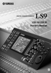
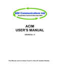
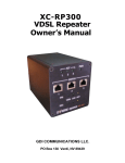
R800-16PCPS Manual
R800-16PCPS
DUAL REDUNDANT POWER SUPPLY
FOR THE
R800-16 RACK
USER MANUAL
PSR800-16MAN
1
R800-16PCPS Manual
2
R800-16PCPS
DUAL REDUNDANT POWER SUPPLY
USER’S MANUAL
DRAWING # A00728 Rev. A
GDI Communications, LLC
280 Interstate 80 Exit 1
Verdi, Nevada 89439
775-345-8000
This Manual applies to units with serial numbers GDI 000000 and up.
APPROVED:
Engineering_______________________________ Date_______________
Manufacturing_____________________________ Date _______________
Marketing_________________________________ Date _______________
Release Date: 1-09-03
PSR800-16MAN
R800-16PCPS MANUAL
3
TABLE OF CONTENTS
USER MANUAL ................................................................................................................ 1
R800-16PCPS ................................................................................................................. 2
SPECIFICATIONS ..................................................................................................... 4
OPERATION .............................................................................................................. 5
INSTALLATION ....................................................................................................... 5
PSR800-16MAN
R800-16PCPS MANUAL
4
GENERAL DESCRIPTION
SPECIFICATIONS
The R800-16PCPS Power Supply is a dual
redundant power supply for the R800-16
Rack assembly. This power supply has two
power supply panels, which can be hot
swapped. Each panel by itself is capable of
powering eight R800-16 Racks. The load is
shared equally between the two Power
Supply panels when two Power Supply
Panels are used. If one of the panels fails,
the other panel will take over the load and
the defective power supply panel can be
replaced without powering down the
Modem Racks.
POWER SUPPLY PANEL
The two Power Supply panels are
connected to the Power Control panel
which ORs the outputs of the two Power
Supply Panels together and distributes the
power to the Racks. Each Rack has its own
power cable and there are two breakers for
each Rack, one for the +12V supply and
one for the –12V supply. If a breaker trips,
its button will pop out indicating an over
current condition. After the problem has
been fixed, the breakers can be reset by
pushing the reset button back in.
INPUT BREAKERS………..10 AMPS
There is an LED above each Breaker on the
Power Control Panel that indicates that the
correct voltage levels are available at the
racks. If the voltage is less than 11.5 Volts
the LED will be dark. Also, if the Power
Cable is disconnected, both of the LEDs
will be dark.
SIZE……….12.25” X 19” X 3” PANEL
WEIGHT………..APPROX. 10 lbs
POWER REQUIREMENTS
INPUT VOLTAGE………..90-264 VAC
FREQUENCY……………...47-63 Hz
POWER FACTOR………….0.99
OUTPUT VOLTAGE………±12 Volts
OUTPUT CURRENT…42 AMPS @ 50º C
OVER VOLTAGE SETTING…16.3V
CURRENT SHARING…………10% Min.
HOLDUP TIME…………….20 MS Min.
THERMALLY PROTECTED
SHUTDOWN AND NO MINIMUM
LOAD
POWER CONTROL PANEL
SIZE………………….8.75”X 19” X 6”
CONNECTORS:
Each of the panels is less than 6” deep so
the panels can be mounted to the backside
of a standard 19” rack and not interfere
with the components on the front of the
rack.
PSR800-16MAN
8 RACK POWER CONNECTORS
2 POWER SUPPLY PANEL
CONNECTORS
R800-16PCPS MANUAL
OPERATION
The R800-16PCPS Power Supply system
consists of two Power Supply Panels and
One Power Control Panel. The Power
Supply Panels supply ± 12 Volts to the
Control Panel.
The Control Panel receives the ± 12 Volts
from each panel through their respective
Power Cables and ORs them together
through high power schottky diodes. The
schottky diodes have a much lower Voltage
drop than standard diodes so less power is
wasted in the ORing (combining) of the
current from the two Power Supply Panels.
The schottky diodes are required to prevent
one power supply from affecting the other.
The sense lines and current share control
lines monitor the voltage after the schottky
diodes to compensate for the losses in the
wire and control circuitry.
The Power Supply Panel contains two
separate power supplies, one for the + 12
Volts and One for the –12 Volts. These
supplies are completely independent but
use the same kind of power supply for each
Voltage. Each power supply has its own
panel mounted 10 Amp circuit breaker and
voltage monitor circuit. The circuit
breakers also serve as an ON/OFF switch
and looks like a toggle switch on the front
panel. The LED above the circuit breakers
indicates whether the respective power
supply is generating its proper voltage.
The Power Control Panel takes the power
from the Power Supply Panels and
distributes it to the R800-16 Modem Racks.
The power comes into the Power Control
Panel through the 2 larger circular plastic
connectors and is distributed to the Racks
through the 8 smaller Circular connectors.
The current for each supply for each Rack
PSR800-16MAN
5
flows through a 7 Amp circuit breaker
before going to the Rack connectors. There
are 16 circuit breakers located on the front
panel. Each one is labeled for the rack and
the Voltage it controls. The LED above
each circuit breaker indicates that the
Voltage on the backpanel of the Rack is
good. If the +12 Voltage drops below 10.5
Volts, the LED will go out. If the –12 Volts
drops below –10.5 Volts its LED will also
go out. If the cable to the rack is
disconnected, both LEDs will be out.
INSTALLATION
The installation of this Power Supply
system is very easy. The 3 panels should be
mounted in a standard 19” Rack. The
power cables connected to the Power
Supply Panels are only 3’ long to keep
losses to a minimum so the panels should
be located as close as possible to each
other. One Power Supply Panel can be
above the Control Panel and the other one
can be below it. You could also have the
Power Control Panel on the front of the
rack and the Power Supply Panels on the
back of the rack.
The Power Cables from the Power Supply
Panels can be connected to either of the
larger circular connectors on the back of
the of the Control Panel. The connectors
are keyed so they cannot be put on
incorrectly.
The back of the Power Supply Panels
contains high Voltages and can be
dangerous if contact is made with these
Voltages. Please disconnect the power cord
from these panels before removing these
panels or troubleshooting them.
The cords from the Power Supply Panels
have a standard NEMA plug on the end
and can be plugged into a standard
R800-16PCPS MANUAL
120VAC outlet. The Power Supplies can
handle any input Voltage from 90 to 265
VAC. If 220 VAC is used, a different cord
may be needed and should be specified at
the time of ordering.
The Power Cable with the Circular
connector is twisted onto the mating
connector on the Power Control Panel. The
connector has a positive stop when fully
engaged. It doesn’t matter which of the two
connectors a particular Power Supply Panel
is plugged into. You don’t need to have
both of the Power Supply Panels Plugged
in for this power supply system to work
correctly. One Panel can supply current for
8 Modem racks. Two panels give you
redundancy and prevent down time in the
event of a single Power Supply Panel
failure.
The front of the Power Supply Panels have
two toggle actuated circuit breakers
installed. These are to control the current
going to the +12V and -12V power
supplies. Circuit breakers are used instead
of fuses so you don’t have to worry about
keeping spare fuses around in case of a
problem. The circuit breakers are on when
the toggle is in the up position. They are
off or tripped in the down position. When
powering the system on, turn the +12V
Circuit breaker on first and then the –12V
circuit breaker. Most modules prefer to
have the +12V applied before the negative
voltage.
If a toggle on a circuit breaker is found to
be tripped, please investigate for the cause
of the over current condition before
resetting the circuit breaker.
The LED above each circuit breaker
indicates that the Power Supply is
supplying the correct voltage. If the Led is
dark and the circuit breaker is on, then
PSR800-16MAN
6
there is a problem with the power supply
and should be repaired. The LED should be
on even if there is no load on the power
supply.
The Power Control Panel takes the power
from the Power Supply Panels and divides
it between the 8 Modem Racks. There are
no high voltages on the Power Control
Panel but there is a lot of current available
which could easily melt a small
screwdriver if placed across the wrong
points.
The Power Control Panel supplies power to
the Racks through 8 nine-pin circular
connectors. The cables from are wired one
to one and connect to similar connectors on
the back of the Modem Rack. The Modem
Racks can be connected to any of the
connectors on the Control panel. The
connectors have corresponding circuit
breakers and LEDs on the front panel that
are labeled RACK1 to RACK8. Each rack
will have two circuit breakers and two
LEDs, one for +12V and one fro –12V.
The LEDs indicate that the voltage on the
back of the MODEM RACK is correct. A
wire in the cable to the Modem Rack
brings back the voltage on the Rack Back
Panel so it can be checked. If a cable is not
connected to a Modem Rack, the LEDs
will be dark.
CONN
J1
J6
J7
J8
RACK
1
2
3
4
CONN
J15
J16
J18
J17
RACK
5
6
7
8
The Table above shows how the connectors
are related to the Rack number. When
looking at the back of the Control Panel, J1
is in the upper left corner. J6 is below it.
R800-16PCPS MANUAL
7
The front panel circuit breakers will trip if
the Modem Rack is drawing more than 7
Amps. This is usually caused by a short
some where in the Rack. The Modem
connectors in the Rack have there own
solid state fuses so a problem that would
blow a breaker on the Control Panel is
probably on the Back panel of the Rack or
mother board.
Because all of the connectors are keyed and
are of different sizes, you cannot connect
any of the cables wrong.
If an LED is out it means that the circuit
breaker is blown and/or the voltage on the
back of the Modem Rack is below
allowable limits. The circuit breaker can be
reset by pushing the button back in. The
problem that caused the circuit to blow
should be fixed before the circuit breaker is
reset.
Below is the pin out for the Rack power
cable:
PIN NUMBER
1,2
3
4,5
6
7,8
9
FUNCTION
+12V
+12V Sense
-12V
-12V Sense
Ground
Equipment Gnd
Below is the pin out for the Power Supply
Connector:
Pin #
1
2
3
4
5
6
7
Function
Share PS1
+12v PS1
Sense 1
Com 2
Com 1
-12V PS2
PSR800-16MAN
Pin #
8
9
10
11
12
13
Function
GND
Sense 2
Chs Gnd
Share PS2
GND
Chs Gnd
MAINTENANCE and
ADJUSTMENTS
The R800-16PCPS Power Supply system
does not require any preventative
maintenance or adjustment for the life of
the product. If one of the Power Supply
Panels needs to be replaced, it can be done
so without turning the power off to the
other panel. The system can operate with
just one Power Supply Panel indefinitely.
R800-16PCPS MANUAL
This is a layout of the back panel of the Power Control Panel
PSR800-16MAN
8
R800-16PCPS MANUAL
9
GDI COMMUNICATIONS, LLC
280 I-80 EXIT 1 WEST
VERDI, NEVADA 89439
775-345-8000 FAX 775-345-8010
WWW.SGDI.COM
PSR800-16MAN