1
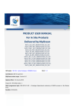
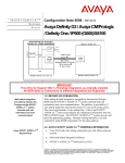
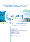
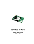
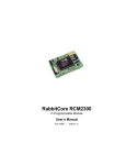
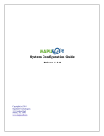
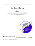
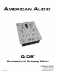
Proc. of the IEEE/OES Seventh Working Conference on Current Measurement Technology Development of a Cheap, GPS-Based, Radio-Tracked, Surface Drifter for Closed Shallow-Water Bays John C. Perez, James Bonner, F.J. Kelly, Chris Fuller [email protected]; [email protected]; [email protected]; [email protected] Conrad Blucher Institute for Surveying and Science Texas A&M University-Corpus Christi 6300 Ocean Drive, Corpus Christi TX, 78412 (361) 825-5891 Abstract -- This paper describes the development of an inexpensive (~ $500), GPS-based, radio-tracked, surface-drifter system designed to operate within a closed shallow water bay. Texas bays and estuaries are generally shallow, weather/event driven, complex non-linear systems. In spite of the amount of activity that occurs within the bays, very little real-time information is collected. The Conrad Blucher Institute for Surveying and Science (CBI) at Texas A&M University-Corpus Christi is working toward better understanding of these bays by operating a pair of SeaSondeTM HF Radar units within Corpus Christi Bay. This experience has shown the need for a specialized drifter that can be used in conjunction with the HF Radar operation and other bay research activities. board that various off-the-shelf components can plug into. All the components operate on 5V, which is supplied by a DC/DC converter, built on the main board. The DC/DC converter is used, instead of a linear regulator, because it allows for a wider range of battery pack voltages yet offers an operating efficiency in the range of 80-90%. The main board also features a 3.3V Li-ion backup battery used to maintain the real-time clock on the micro-controller and to reduce the startup time of the GPS. I. INTRODUCTION The main design criteria used in the development of this shallow water surface drifter are that it be inexpensive, operate in a closed, shallow bay environment, be self-logging and have the ability to operate in either autonomous or realtime tracking modes. A radio link also offers a means to download the data-log and program the unit without opening it. The drifter design was broken into two parts: the hardware/software characteristics (including GPS, radio, battery, software), and the drifter housing. Only the hardware/software system (Table I), costing around $500, is discussed in detail below. Fig. 1. Electronics board showing left to right and top to bottom, radio, micro-controller, GPS, backup battery, DC/DC voltage converter. Although the initial design took a simplistic approach that doesn’t use any method of advanced power reduction, it is a workable design thanks to the relatively low-power nature of the individual components, as shown in Table II. Future versions are planned that will allow for turning off and/or putting to sleep devices when they aren’t needed, which would achieve roughly a 2/3 reduction in power. Even as built, the 2.2-Ah, 12-V, lead-acid batteries used for the development will operate the electronics for about six hours. Table I COST ITEMIZATION OF DRIFTER’S ELECTRICAL COMPONENTS Item Micro-Controller Radio GPS Circuit board Battery Miscellaneous items Total Cost $42.00 $201.00 $93.00 $91.00 $21.00 $40.00 $488.00 Table II POWER CONSUMPTION OF THE DRIFTER FOR EACH OF THE TWO OPERATING STATES Device Micro-controller GPS Radio Fully running Power 16.7% duty cycle power II. DRIFTER The electronics portion of the drifter fits on a 7.5x22 cm board as shown in Fig. 1. This small size makes it capable of being used in a wide variety of drifter enclosures. The board follows a modular design, and consists of a main circuit 0-7803-7813-X/03/$17.00 ©2003 IEEE Power Consumption (Watts) Transmit Receive Sleep 0.9 0.9 0.10 1.1 1.1 0.00 0.7 0.3 0.13 2.30 0.68 Other battery chemistries such as NiCd, Alkaline, and Liion offer performance improvements in the available power, 66 Proc. of the IEEE/OES Seventh Working Conference on Current Measurement Technology battery volume, and weight. A rechargeable 15-V, 15-Ah, Liion pack would occupy roughly the same space, weigh 1/4 less, and cost an order of magnitude more ($223), but would extend the operating time to about 64 hours running continuously, or on the order of nine days with power management strategies. Regardless of the battery type, the drifter housing is designed to accomplish recharging without opening it. For initial development, the NMEA message GGA (Global Positioning System Fixed Data) is used, and only the UTC time, Latitude, and Longitude are stored. Although it is generally preferred to store the entire message, it was parsed in order to reduce the storage. The GPS offers both a lowpower sleep mode and a shut off mode, but neither of these features was utilized for the initial design. Another feature being explored is using the differential GPS (DGPS) option built into the receiver by re-broadcasting a differential signal to the drifter over the telemetry link, which would improve accuracy and precision of the computed water speed. A. Microprocessor The design is based around the RCM2300 microprocessor core module from Rabbit Semiconductor. This microprocessor was chosen because of is low-cost, ease of use, low power, and because it has enough built-in resources to accomplish the needed tasks. The core module version of this chip allows for rapid development by providing all the needed support circuits in an easy to use package. Using the core modules doesn’t prevent future versions of the drifter from eliminating the modules and directly incorporating the needed support chips for improved capabilities such as more data storage. The core module features a 22.1 MHz clock, 256K Flash & 128K SRAM memory, Real-time clock, 29 I/O lines, and 4 serial ports. The module is relativity small (41x29x12 mm) and has minimal power consumption while supporting a real-time operating system that uses the “C” programming language [1]. The controlling software can be downloaded into the flash memory while the SRAM is used for data storage. C. Radio The radio link used to communicate with the drifters is based on a 100-mW, 900-MHz, frequency-hopping, spreadspectrum, OEM transceiver manufactured by MaxStream [3]. It is a physically small and low power device with many features. The 1200-bps radio-to-radio version was used for its increased range. In addition to real-time tracking, a radio provides the capability to download data and program the drifter without disassembling it. In fact, the data can be retrieved without interrupting the drifter’s ongoing operation. The radio’s range is constrained by the physical limitation of the need to have a rather low-profile drifter housing. This limits the drifter’s antenna height. Since the drifter operates over water, the range is governed by the interaction of the line-of-sight (Eq. 1) with the interference of the first Fresnel zone (Eq. 2). d hlos = re 1− cos 1 2re Where: hlos = Line of sight height in meters. re = Effective radius of the earth in meters. d = Distance between transmitter and receiver in meters. B. GPS The GPS used is an OEM module that is manufactured by Laipac and is based on the SiRF star I/LXTM chip set. It is a 12-channel receiver with a position accuracy of 25 m CEP without SA [2]. The drifter utilizes the active antenna option of the GPS as shown in Fig. 2. The GPS outputs variety of NMEA (Nation Marine Electronics Association) messages that are parsed for the needed information. hn = nλ d 2 Where: n = Fresnel zone number. hn = Height of the Fresnel radius for zone n in meters. λ = Wavelength of radio wave in meters. d = Distance from the transmitter to point in meters. Initial calculations determined that for a 6-m high base antenna and a 0.5-m high drifter antenna the expected radio range is about 900 m. This value corresponds to what was found by field-testing the radio link. Range can be improved by modifications to the system. First a 2.4-GHz version of the radio can be used. The increase in operating frequency will decrease the effects of the Fresnel-zone interference, which will increase the range. Second, the drifter antenna can be elevated to 1 m. Lastly, by switching to a 10-m high Fig. 2. Active GPS Antenna mounted on the top of the test drifter. 67 Proc. of the IEEE/OES Seventh Working Conference on Current Measurement Technology determine when to sample because it is always available and doesn’t rely on the operation of the GPS. The final process acts as a master and coordinates the activities of the other processes. It also determines when the drifter is operating in a data-logging mode or in the user interface mode. The user interface provides methods for changing the time on the RTC, changing the sampling rate, and downloading the data, as well as other functions, as shown in Fig. 4. antenna located on a platform in Corpus Christi Bay the expected range should be about 7 km. D. Software The software used to control the drifter was written in “C” and utilizes the real-time operating system µcos. Using the µcos operating system allows for breaking the firmware into discrete tasks and then creating an independent process designed to accomplish each task. Four tasks were defined that needed to be addressed by the drifter software, they are: communication with the radio, communication with the GPS, timekeeping, and a coordinating task to interconnect the other tasks into a functioning product. The process that communicates with the radio accepts data coming from the radio and queues the characters until a full line of data has been received, as signaled by a carriagereturn. This process, allows the rest of the software to only deal with full commands, and not worry about each byte of information as it comes in. This method also allows for future enhancements such as implementing checksum bytes for error detection and retransmission of lost data. The task of communication with the GPS includes parsing the NMEA messages. For now, only the GPS time, Latitude and Longitude are parsed from the NMEA GGA message. Although the internal clock of the microprocessor is used for operating the drifter, the GPS time is used to coordinate the data retrieved from several drifters. Although the GPS also reports the NMEA VTG (course over ground and ground speed), which contains “land speed information”, this information is not being used. While the VTG message would provide an instantaneous speed and bearing, a more accurate measurement can be obtain by calculating the speed of the drifter from the distance traveled and the time difference. The expected errors using the worst-case values from the GPS are shown in Fig. 3 for various time intervals. CBI Drifter 1 --- Help Menu 2 --- Display Time 3 --- Set Time 4 --- Read GPS 5 --- Download Data 6 --- Print Out Latest Data 7 --- Change Sampling Rate 8 --- Exit Menu Fig. 4. User menu from the drift drifter showing the available options III. DRIFTER OPERATION The electronics portion of the drifter along with the test housing is shown in Fig. 5. The drifter is designed to operate in a variety of different modes ranging from self-contained to remote tracking. This variety results from the different uses planned by CBI. Reported Error vs. Water Current 50% 40% Fig. 5. Initial testing of the prototype drifter. For this version 1.6-cm (4-in.) PVC pipe was used. Since then everything has been shrunk to fit into a 1.2cm (3-in.) PVC pipe with a longer and narrower antenna. 30% 20% 10% A. Self-contained mode 0% 0 5 10 15 20 25 30 Water Current cm/s 6-min 30-min The simplest mode is the self-contained (un-tracked) mode. In this mode the drifters are deployed where needed, and the drift logs are retrieved after recovery. A major drawback with this mode is the required visual tracking of the individual drifters that are deployed. The use of this mode of operation is planned for “spot checking” areas of interest. 60-min Fig. 3. The expected water current error for using a time interval of 6, 30, and 60 minutes. An independent task is used to keep track of the CPU time and to determine when to take a sample. This task provides an easy method for changing the sampling rate and the time the radio will transmit. The CPU clock was chosen to 68 Proc. of the IEEE/OES Seventh Working Conference on Current Measurement Technology B. Boat-based drifter tracking Over the past year CBI has been developing and operating a “spill of opportunity” vessel [4]. This vessel is equipped with an ADCP, dual-frequency fathometer, and a towed, Acrobat™ sensor package: CTD, fluorometer, particle size analyzer, etc. In this mode, a group of drifters can be deployed, tracked from the boat in real-time, and treated as part of the sensor suite. C. Fixed-based drifter tracking mode The third mode of operation planned for the drifters is in support of the fixed monitoring platforms and HF-Radar that CBI operates. The platforms are equipped with a sensor suite similar to that of the “spill of opportunity” boat, but are used to record time-series information about the bays. In this mode the drifters can be deployed around the platform during routine service trips and tracked real-time by the data-loggers already present on the platforms. Fig. 6 Typical drifter drift track within Corpus Christi Bay, the drifter sampled its location every 10 minutes. V. SUMMARY IV. DATA RETRIEVAL SYSTEMS The initial development of the drifter accomplished the goal of a simple to use, inexpensive (~ $500), shallow-bay, surface drifter. Based on what was learned several changes are planned that will increase the drifter’s usefulness (but not the cost) such as the ability to power down or put to sleep the drifter between samples, which will significantly increase the battery life. Changing the operating frequency of the radio, which will improve the range that the drifters can be tracked, is another improvement planned. Software enhancements such as error detection and packet retransmission will allow for more a more robust data link. Drifter data are retrieved via its radio. The “base station” radio that communicates with the drifter has been implemented in two versions. A. Radio with Rabbit core A RCM2200 rabbit-core is interfaced to the same radio model used in the drifter. It is essentially the same as the RCM2300 that is used in the drifter but it includes an Ethernet port. The Ethernet port allows the base station to FTP the drifter data directly to a fileserver for use and archiving. It also allows the user the ability to “Telnet” into the base station in order to modify its operation, such as how often the data are transferred to the fileserver. This version of the base station is used for downloading the data from the drifters when they are operated in the self-contained mode and during the boat-based tracking deployments. ACKNOWLEDGEMENTS This work was supported by the Texas General Land Office under the Interagency Cooperation Contracts 00-43R and 02115R. B. Radio with Data-logger REFERENCES This version of the base station is simply a radio connected to one of the serial ports of an existing data-logger. With this method the information reported by the drifter will be treated as another sensor attached to the data-logger. This method is planned for deployment around existing data-collecting platforms. The existing data-loggers can be set up so that when a platform undergoes regularly scheduled service the drifters can be deployed and recovered with the data automatically retrieved and transmitted back to CBI, i.e., independently of the field personnel’s’ tasks (See Fig. 6) [1] Rabbit Semiconductor, Davis, CA, [online], Available: http://www.rabbitsemiconductor.com [2] GPS Engine Board TF Series, Laipac Technology Inc., Ontario, Canada, [user manual]. [3] MaxStream, Orem, UT, [online], Available: http://www.maxstream.net [4] T. Ojo, J. S. Bonner, M. Sterling, F. J. Kelly, C. A. Page, J. Perez, C. Fuller, Adaptive sampling for coastal environmental monitoring using a geo-referenced mobile platform, 3rd euroGOOS conference 2002, “in press”. 69