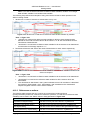
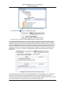
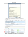
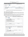
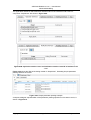
1
ASD:Suite Release 3 v7.0.1 User Manual Copyright © 2011 Verum Software Technologies B.V. ASD is licensed under EU Patent 1749264 and Hong Kong Patent HK1104100 All rights are reserved. No part of this publication may be reproduced in any form or by any means, electronic, mechanical, photocopying, recording, or otherwise, without the prior written permission of the copyright owner. ASD:Suite Release 3 v7.0.1 - User Manual TABLE OF CONTENTS 1 INTRODUCTION TO ASD:SUITE CONCEPTS ..........................................................................7 1.1 THE ASD:SUITE ...................................................................................................................7 1.2 PURPOSE.............................................................................................................................7 1.3 ASD CONCEPTS ..................................................................................................................7 1.3.1 Components ...............................................................................................................7 1.3.1.1 ASD components .........................................................................................7 1.3.1.2 Foreign components.....................................................................................7 1.3.2 Sequence-Based Specifications.................................................................................8 1.3.3 Models ........................................................................................................................9 1.3.3.1 Interface Model.............................................................................................9 1.3.3.2 Design Model .............................................................................................10 1.3.4 The ASD Triangle and Correctness..........................................................................11 1.4 HANDS-ON ASD:SUITE TRAINING AVAILABLE ........................................................................11 2 INSTALLATION .........................................................................................................................12 2.1 PREREQUISITES .................................................................................................................12 2.2 INSTALLATION PROCESS .....................................................................................................12 2.3 CONNECTION TO THE ASD:SERVER ....................................................................................13 3 THE USER INTERFACE ...........................................................................................................16 3.1 TOOL-WINDOWS AND PANES ..............................................................................................16 3.2 SBS TAB COLOURS ............................................................................................................20 3.3 SBS TAB CONTEXT INFORMATION FIELD ...............................................................................21 3.4 MENUS ..............................................................................................................................22 3.4.1 File ............................................................................................................................22 3.4.2 Edit............................................................................................................................23 3.4.3 View ..........................................................................................................................24 3.4.4 Filters ........................................................................................................................24 3.4.5 Tools .........................................................................................................................25 3.4.6 Help...........................................................................................................................26 3.5 TOOLBAR BUTTONS ............................................................................................................26 3.6 STATUS BAR.......................................................................................................................28 4 GETTING STARTED .................................................................................................................30 4.1 OVERVIEW .........................................................................................................................30 4.2 START THE ASD:SUITE ......................................................................................................30 4.3 CREATE ASD MODELS ........................................................................................................31 4.3.1 Create a new interface model...................................................................................31 4.3.2 Create a new design model ......................................................................................34 4.4 CREATE AN APPLICATION INTERFACE AND SPECIFY EVENTS FOR IT .......................................35 4.4.1 Create an application interface.................................................................................35 4.4.2 Specify application call events and application reply events....................................36 4.5 CREATE A NOTIFICATION INTERFACE AND SPECIFY EVENTS FOR IT ........................................38 4.5.1 Create a notification interface ...................................................................................38 4.5.2 Specify notification events ........................................................................................39 4.6 CREATE A MODELLING INTERFACE AND SPECIFY EVENTS FOR IT ...........................................39 4.6.1 Create a modelling interface.....................................................................................39 4.6.2 Specify modelling events ..........................................................................................40 4.7 CREATE TAGS, A.K.A. REQUIREMENTS .................................................................................41 4.8 SPECIFY BEHAVIOUR IN AN ASD MODEL...............................................................................41 4.8.1 Preliminary steps before specifying behaviour .........................................................41 4.8.1.1 Specify state variables ...............................................................................42 4.8.1.2 Specify state information ............................................................................43 4.8.1.3 Add design information for states...............................................................43 4.8.2 Specify behaviour – Fill in a rule case ......................................................................44 4.8.2.1 Specify actions ...........................................................................................44 4.8.2.2 Specify target state.....................................................................................46 4.8.2.3 Specify comments ......................................................................................47 Copyright © 2011 Verum Software Technologies B.V. Page 2 of 185 ASD:Suite Release 3 v7.0.1 - User Manual 4.8.2.4 Specify tags ................................................................................................48 4.8.2.5 Specify guards............................................................................................49 4.8.2.6 Specify state variable updates ...................................................................50 4.8.3 Add and/or Delete a rule case ..................................................................................50 4.8.4 Insert and/or Replace rule cases..............................................................................51 4.8.5 Jump to an existing state ..........................................................................................51 4.8.6 Find the first rule case leading to a state..................................................................51 4.8.7 Duplicate a state .......................................................................................................51 4.8.8 Specify non-deterministic behaviour.........................................................................52 4.8.9 Specify behaviour in a design model – additional steps...........................................52 4.9 SPECIFY USED SERVICES ....................................................................................................53 4.9.1 Specify primary references .......................................................................................53 4.9.2 Specify different components with the same service ...............................................55 4.9.3 Specify connected interfaces....................................................................................56 4.9.4 Specify secondary references ..................................................................................56 4.9.5 Remove a used service ............................................................................................57 4.10 SPECIFY BEHAVIOUR USING USED SERVICE REFERENCE STATE VARIABLES ............................58 4.10.1 Specify used service reference state variables ........................................................58 4.10.2 Operators for used service reference state variables...............................................59 4.10.3 References as actions ..............................................................................................61 4.11 FIND AND REPLACE DATA IN AN ASD MODEL ........................................................................62 4.12 FILTER DATA IN AN ASD MODEL ..........................................................................................64 4.12.1 Definitions for “filter” and “rule case attributes”.........................................................64 4.12.2 Selection and application of filters ............................................................................65 4.12.3 Editing the custom filter ............................................................................................65 4.12.3.1 Custom Filter expressions..........................................................................66 4.12.3.2 Custom Filter elements ..............................................................................66 4.12.3.2.1 Adding Custom Filter elements ........................................................67 4.12.3.2.2 Deleting Custom Filter elements ......................................................68 4.12.3.3 OK and Cancel buttons ..............................................................................69 4.12.3.4 The Clear button.........................................................................................69 4.13 SAVE AN ASD MODEL .........................................................................................................70 4.14 LOAD AN EXISTING ASD MODEL ..........................................................................................70 4.15 UPGRADE ASD MODELS BUILT WITH PREVIOUS ASD:SUITE RELEASES ..................................71 4.16 GENERATE AND EXPORT STATE DIAGRAMS FOR AN ASD MODEL............................................72 4.17 PRINT AN ASD MODEL ........................................................................................................75 5 ADVANCED MODELLING ........................................................................................................78 5.1 DETAILED ASPECTS OF EDITING ASD MODELS .....................................................................78 5.1.1 State types ................................................................................................................78 5.1.2 Operational Semantics of rule cases........................................................................78 5.1.2.1 Client requests ...........................................................................................78 5.1.2.2 Notification interfaces .................................................................................79 5.1.2.3 ASD Timers and the Timer Cancel Guarantee ..........................................79 5.2 ADD SUB MACHINES ............................................................................................................79 5.3 SPECIFY STATE INVARIANTS IN AN ASD MODEL ....................................................................81 5.4 SAVE AS ............................................................................................................................81 5.5 CREATE AN ASD MODEL FROM AN EXISTING ONE .................................................................82 5.5.1 Create an ASD model of the same type as the currently opened one .....................82 5.5.2 Create an ASD model as a copy of an ASD model stored on disk ..........................83 5.6 REASSIGN INTERFACE MODEL DEPENDENCIES IN A DESIGN MODEL ........................................84 5.7 SPECIFY PUBLISHERS AND OBSERVERS ...............................................................................86 5.8 USE SINGLETON EVENTS TO RESTRICT NOTIFICATION EVENTS ...............................................89 5.9 USE YOKING THRESHOLD TO RESTRICT NOTIFICATION EVENTS .............................................90 5.9.1 Yoking .......................................................................................................................90 5.9.2 WARNING.................................................................................................................91 5.9.3 Yoking threshold for notification events....................................................................91 5.9.4 Effect of Yoking.........................................................................................................91 5.10 IGNORE WARNING DIALOGS .................................................................................................92 5.11 SERIALISE ASD COMPONENTS ............................................................................................93 5.12 PARAMETER USAGE ............................................................................................................94 Copyright © 2011 Verum Software Technologies B.V. Page 3 of 185 ASD:Suite Release 3 v7.0.1 - User Manual 5.12.1 Parameter declaration ..............................................................................................94 5.12.2 Simple parameter passing ........................................................................................95 5.12.3 Changing the number of parameters........................................................................97 5.12.4 Renaming the parameter in the trigger of a rule case ..............................................98 5.12.5 Specifying arguments for an action ..........................................................................98 5.12.6 Parameter storage ....................................................................................................98 5.12.6.1 Component variables .................................................................................99 5.12.6.2 Storage specifiers.......................................................................................99 5.12.6.2.1 >> – Transfer to a component variable ............................................99 5.12.6.2.2 << – Retrieve from a component variable........................................99 5.12.6.2.3 >< – Retrieve from and Store to component variable ................... 100 5.12.6.2.4 Example ........................................................................................ 100 5.12.7 Parameters in the generated code ........................................................................ 101 5.12.7.1 Parameter passing in general ................................................................. 101 5.12.7.2 Parameter passing in C++....................................................................... 102 5.12.7.3 Parameter passing in C#......................................................................... 102 5.12.7.4 Parameter passing in C........................................................................... 103 5.12.7.5 Parameter passing in Java...................................................................... 104 6 CHECK AND FIX CONFLICTS IN AN ASD MODEL............................................................. 106 6.1 CHECK CONFLICTS .......................................................................................................... 106 6.2 FIX CONFLICTS ................................................................................................................ 106 6.2.1 Fix “Reconcile conflicts”......................................................................................... 106 6.2.2 Fix “Syntax errors” ................................................................................................. 108 6.2.3 Fix “Specification conflicts” .................................................................................... 110 6.2.3.1 Fix interface model related specification conflicts ................................... 110 6.2.3.2 Fix name duplicates ................................................................................ 110 6.2.3.3 Fix argument, parameter or component variable related specification conflicts 111 6.2.3.4 Fix interface related specification conflicts.............................................. 113 6.2.3.5 Fix broadcasting and Singleton event related conflicts........................... 114 6.2.3.6 Fix used service related specification conflicts ....................................... 114 6.2.3.7 Fix rule case related specification conflicts ............................................. 116 6.2.3.8 Fix state variable and guard related specification conflicts..................... 119 6.2.4 Automated conflict fixing........................................................................................ 121 6.2.4.1 Automatically fix syntax errors................................................................. 121 6.2.4.2 Automatically fix specification conflicts ................................................... 121 7 VERIFY AN ASD MODEL ...................................................................................................... 121 7.1 PREPARE A DESIGN MODEL FOR VERIFICATION.................................................................. 121 7.2 VERIFY MODELS USING THE ASD:SUITE ........................................................................... 122 8 GENERATING CODE FROM AN ASD MODEL .................................................................... 128 8.1 PREPARE THE ASD MODEL FOR CODE GENERATION .......................................................... 128 8.1.1 Specify component type ........................................................................................ 128 8.1.2 Specify execution model........................................................................................ 128 8.1.3 Specify target language and code generator version............................................ 129 8.1.4 Specify namespace (or package) .......................................................................... 130 8.1.5 Specify output path and attribute code with tracing information............................ 130 8.1.6 Ensure correct referencing of user defined types.................................................. 132 8.1.7 Specify path to user provided text for code customization .................................... 133 8.2 GENERATE CODE USING THE ASD:SUITE .......................................................................... 135 8.3 GENERATE STUB CODE FOR FOREIGN COMPONENTS USING THE ASD:SUITE ...................... 136 8.4 DOWNLOAD THE ASD:RUNTIME USING THE ASD:SUITE .................................................... 138 8.5 HANDWRITTEN CLIENTS ................................................................................................... 139 8.5.1 Example for illustrating Handwritten Clients .......................................................... 139 8.5.2 C++ code for a Handwritten Client ........................................................................ 139 8.5.3 C# code for a Handwritten Client........................................................................... 140 8.5.4 C code for a Handwritten Client............................................................................. 141 8.5.5 Java code for a Handwritten Client........................................................................ 142 8.6 HANDWRITTEN SERVERS (USED COMPONENTS) ............................................................... 143 8.6.1 Example for illustrating Handwritten Servers......................................................... 143 Copyright © 2011 Verum Software Technologies B.V. Page 4 of 185 ASD:Suite Release 3 v7.0.1 - User Manual 8.6.2 8.6.3 8.6.4 8.6.5 9 C++ ........................................................................................................................ 143 C# .......................................................................................................................... 144 C ............................................................................................................................ 144 Java ....................................................................................................................... 144 USING THE ASD:SUITE FROM THE COMMAND LINE....................................................... 145 9.1 UPGRADE ASD MODELS USING THE COMMAND LINE .......................................................... 145 9.2 UPDATE INTERFACE CHANGES IN DESIGNS ........................................................................ 145 9.3 GENERATE CODE USING THE ASD:COMMANDLINE CLIENT ................................................. 145 9.4 GENERATE STUB CODE FOR FOREIGN COMPONENTS USING THE ASD:COMMANDLINE CLIENT 146 9.5 DOWNLOAD THE ASD:RUNTIME USING THE ASD:COMMANDLINE CLIENT ........................... 147 APPENDIX A. MODEL SPECIFICATION RULES ................................................................. 148 A.1 CONTEXT ........................................................................................................................ 148 A.2 SPECIFICATION RULES ..................................................................................................... 148 A.2.1 SYNTACTICAL RULES FOR NAMES USED IN ASD MODELLING ...................................148 A.2.2 SYNTACTICAL RULES FOR NAMESPACE/PACKAGE NAMES USED IN ASD MODELLING .............................................................................................................................149 APPENDIX B. DEPENDENCIES FOR THE ASD GENERATED SOURCE CODE ............... 150 APPENDIX C. EXAMPLES OF CUSTOMIZED CODE .......................................................... 151 C.1 TEXT FILE WITH COPYRIGHT INFORMATION ........................................................................ 151 C.1.1 FILE CONTENTS.................................................................................................................151 C.1.2 EFFECT 151 C.1.3 GENERATED SOURCE FILE..............................................................................................151 C.2 TEXT FILE WITH <GENERATE/> DIRECTIVE ........................................................................ 152 C.2.1 FILE CONTENTS.................................................................................................................152 C.2.2 EFFECT 152 C.2.3 GENERATED SOURCE FILE..............................................................................................152 C.3 TEXT FILE WITH <INCLUDE> AND <GENERATE/> DIRECTIVES ............................................. 152 C.3.1 C.3.2 C.3.3 C.3.4 COPYRIGHTBLOCK.TXT CONTENTS ...............................................................................152 FILE CONTENTS.................................................................................................................152 EFFECT 153 GENERATED SOURCE FILE..............................................................................................153 APPENDIX D. INTERFACE DEFINITION FILES HANDWRITTEN (CLIENTS AS) OBSERVERS FOR AN ASD COMPONENT................................................................................. 154 D.1 INTERFACE DEFINITION FILES FOR HANDWRITTEN (CLIENTS AS) OBSERVERS IN C++ .......... 154 D.2 INTERFACE DEFINITION FILES FOR HANDWRITTEN (CLIENTS AS) OBSERVERS IN C#............. 155 D.3 INTERFACE DEFINITION FILES FOR HANDWRITTEN (CLIENTS AS) OBSERVERS IN JAVA .......... 156 D.4 INTERFACE DEFINITION FILES FOR HANDWRITTEN (CLIENTS AS) OBSERVERS IN C............... 158 APPENDIX E. EXAMPLES OF FOREIGN COMPONENT IMPLEMENTATIONS................. 159 E.1 HANDWRITTEN FOREIGN COMPONENT IMPLEMENTATION IN C++........................................ 159 E.2 HANDWRITTEN FOREIGN COMPONENT IMPLEMENTATION IN C#.......................................... 160 E.3 HANDWRITTEN FOREIGN COMPONENT IMPLEMENTATION IN JAVA ....................................... 161 E.4 HANDWRITTEN FOREIGN COMPONENT IMPLEMENTATION IN C............................................ 163 E.5 HANDWRITTEN FOREIGN COMPONENT IMPLEMENTATION HEADER IN C .............................. 164 E.6 HANDWRITTEN GENERIC.H IN C........................................................................................ 165 APPENDIX F. EXAMPLES OF GENERATED STUB CODE................................................. 166 F.1 EXAMPLE STUB CODE FOR C++....................................................................................... 166 F.1.1 GENERATED STUB HEADER FILE....................................................................................166 F.1.2 GENERATED STUB IMPLEMENTATION TEMPLATE FILE ...............................................166 F.2 EXAMPLE STUB CODE FOR C# ......................................................................................... 168 F.2.1 PARTIAL COMPONENT......................................................................................................168 F.2.2 COMPONENT......................................................................................................................168 F.3 EXAMPLE STUB CODE FOR C ........................................................................................... 170 F.3.1 GENERATED STUB HEADER FILE....................................................................................170 F.3.2 GENERATED STUB IMPLEMENTATION HEADER FILE ...................................................171 F.3.3 GENERATED STUB IMPLEMENTATION FILE...................................................................172 F.4 EXAMPLE STUB CODE FOR JAVA ...................................................................................... 174 F.4.1 COMPONENT......................................................................................................................174 F.4.2 COMPONENT IMPLEMENTATION.....................................................................................174 Copyright © 2011 Verum Software Technologies B.V. Page 5 of 185 ASD:Suite Release 3 v7.0.1 - User Manual APPENDIX G. 3RD PARTY DEPENDENCIES FOR THE ASD:SUITE ................................... 176 G.1 BOOST SOFTWARE LICENSE - VERSION 1.0 - AUGUST 17TH, 2003 .................................... 176 G.2 ZLIB COMPRESSION.......................................................................................................... 176 G.3 PUTTY........................................................................................................................... 176 G.4 THE OPENSSL PROJECT ................................................................................................. 177 G.5 CRYPTOSOFT .................................................................................................................. 177 G.6 ARABICA – XML PARSER LIBRARY .................................................................................... 178 G.7 XERCES-C++ – XML PARSER LIBRARY ............................................................................. 179 G.8 GRAPHVIZ LICENSE ......................................................................................................... 182 Copyright © 2011 Verum Software Technologies B.V. Page 6 of 185 ASD:Suite Release 3 v7.0.1 - User Manual Introduction to ASD:Suite concepts 1 INTRODUCTION TO ASD:SUITE CONCEPTS 1.1 THE ASD:SUITE ASD (Analytical Software Design) is Verum’s own technology for software development. ASD makes it possible to create systems from mathematically verified components. This technology is supported by the ASD:Suite. With the ASD:Suite, services and components that implement and use these services can be defined using models that specify both structure and behaviour. Then, automatically: • The models can be verified for behavioural defects; • Full executable source code can be generated for the components. Note: In addition to the Windows desktop client, a command prompt client is available too, the ASD:Commandline Client. For additional ASD:Suite related information, FAQ’s, knowledge base articles, a download library of ASD Models and white papers, and forum threads please see the ASD:Suite Community website. 1.2 PURPOSE The purpose of this document is to introduce the ASD:Suite. It offers a set of guidelines on how to use the various features of the ASD:Suite. This document is intended for all users of the ASD:Suite. In fact, anyone interested in what the ASD:Suite offers to system engineers and product developers, benefits from it. This manual presents the features of the ASD:Suite Release 3 v7.0.1. 1.3 ASD CONCEPTS This section provides background information on the technology behind the ASD:Suite. 1.3.1 Components ASD is a component-based technology in which systems are composed of a mixture of ASD components and Foreign components. Within ASD, a component is a common unit of architectural decomposition, specification, design, mathematical verification, code generation and runtime execution. 1.3.1.1 ASD components ASD components are software components that are specified and designed using ASD. An interface model specifies the externally visible behaviour of a component. A design model specifies its inner working and how it interacts with other components. All ASD Components must have both an interface model and a design model. ASD components are mathematically verified. In the ASD:Suite this is done using a Software as a Service (SaaS) application. The necessary mathematical models are generated automatically from both design and interface models in the process algebra CSP. The source code to implement an ASD component is generated automatically from its design model. 1.3.1.2 Foreign components Foreign components are hardware or software components of a system which are not developed using ASD. As they have to be used by ASD Components, they must correctly interface and interact with them. They may be third party components, legacy code or handwritten components representing those parts of a system that cannot be generated from ASD designs. All used foreign components must have an interface model which specifies the externally visible behaviour of the foreign component. Foreign components do not have a corresponding design model. Copyright © 2011 Verum Software Technologies B.V. Page 7 of 185 ASD:Suite Release 3 v7.0.1 - User Manual Introduction to ASD:Suite concepts The interface model of foreign components is used for two purposes: 1. For verifying ASD components that use these foreign components: CSP models are generated automatically from the interface models. They are used to verify that an ASD component interacts correctly at runtime with the corresponding foreign component. 2. For code generation: to generate the correct interface header files. Note: The handwritten implementation provided for the foreign component must correctly implement all methods declared in the generated interface header files. This includes ASD specific methods like GetInstance, ReleaseInstance, GetAPI, and RegisterCB. 1.3.2 Sequence-Based Specifications According to [IEEE610.12] 1 , a specification is a complete, precise and verifiable description of the characteristics of a system or a component. Within ASD the distinction between an interface specification (interface model) and a design specification (design model) is fundamental. The interface model describes the externally visible behaviour of a component and is as implementation-free as possible. This means that the model defines what the component does under every circumstance but not how the component will do it. The external behaviour is specified independently of any specific implementation. It is an abstraction of the component or system implementation that every compliant design is required to implement. The design model describes the internal behaviour of a component. It rigorously and completely defines one of the many possible implementations that faithfully comply with the interface model. An ASD component implements a service (specified by the interface model) that is used by its clients. This implemented service is exposed by means of application interfaces through which clients can send call events. The ASD component can respond to a call event on an application interface by means of a reply event on the same application interface and events on notification interfaces. In this process, an ASD component can also invoke used services that are implemented by other components: the servers of the ASD component. Collectively, the services between a component and its clients and servers form an imaginary border, called the component boundary. Information crosses the component boundary in the form of events. Figure 1-1: Component boundary A component “knows” only information passed into it across the component boundary in the form of the triggers it receives. A trigger can be: 1 [IEEE610.12]: IEEE Standard Glossary of Software Engineering Terminology; IEEE 610 Working Group – DocID: IEEE Std 610.12-1990(R2002) – Date: 11-09-2002 – Status: Reaffirmed Copyright © 2011 Verum Software Technologies B.V. Page 8 of 185 ASD:Suite Release 3 v7.0.1 - User Manual Introduction to ASD:Suite concepts • A call event from a client through an application interface; • A reply event from a server through an application interface; • A notification event from a server through a notification interface. Similarly, a component exposes information to its clients and servers across the component boundary in the form of the actions it sends. An action can be: • A call event to a server through an application interface; • A reply event to a client through an application interface; • A notification event to a client through a notification interface. An interface model is defined in terms of only those events that pass between a component and its Clients. A design model is defined in terms of events that pass between the component, its Clients and its Servers. Within ASD, both interface models and design models are defined in the form of Sequence-Based Specifications (SBS). Behaviour is specified in a tabular form as a total Black Box function, by mapping all possible sequences of triggers to the corresponding actions. The method used to create these specifications, is called Sequence Enumeration. This requires the systematic enumeration of all possible input sequences of triggers, ordered by length, starting with the empty sequence. Triggers can be repeated within a sequence and since sequence length is not restricted, the set of all possible sequences is infinite. In practice, systems do not display an infinite set of unique, non-repeating behaviours. They cycle through a finite set of states and repeat a finite set of behaviours. Thus the infinite set of input sequences of triggers can be reduced to a finite set of equivalence classes. Each class is identified by a minimal length sequence, called Canonical Sequence. All sequences in a given equivalence class have the same future system behaviour. They are said to be Mealy Equivalent. The equivalence classes form the set of states in a Mealy Machine. The theory underlying this approach tells us that by reasoning about the behaviour of the finite set of Canonical Sequences, we can reason about the behaviour of every possible input sequence. The Sequence Enumeration method used in ASD thus defines the Black Box function as a total function between the finite set of Canonical Sequences and the corresponding actions. 1.3.3 Models ASD supports two types of models: • Interface Model • Design Model In this section we discuss both types of models. 1.3.3.1 Interface Model An interface model is a model of the externally visible behaviour of an ASD component or Foreign component, i.e. the service that the component implements. • It identifies the component’s application interfaces and notification interfaces and specifies their associated events. • It specifies the externally visible behavioural semantics of the component in the form of one Sequence-Based Specification. • It may also specify modelling interfaces with associated events that are hidden from the client and are used to represent hidden internal behaviour of the implementation. • The triggers in an interface model are occurrences of: Call events on application interfaces; Events on modelling interfaces. • The actions in an interface model are occurrences of: Reply events on application interfaces; Events on notification interfaces. Copyright © 2011 Verum Software Technologies B.V. Page 9 of 185 ASD:Suite Release 3 v7.0.1 - User Manual Introduction to ASD:Suite concepts 1.3.3.2 Design Model A design model is a model of the internal behaviour of an ASD component. • Its implemented service and used services are specified by interface models; • It fully and deterministically specifies the internal logic of the component as one or more Sequence-Based Specifications; A simple design is represented by a single Sequence-Based Specification; A complex design is partitioned hierarchically into a main machine and one or more sub machines. Each of these is specified by a Sequence-Based Specification. • If the design is partitioned: There is one transfer interface defined for each sub machine through which the main machine and sub machine communicate. Transfer interfaces are not visible to clients or servers. • The triggers in a design model are occurrences of: Call events on application interfaces of the implemented service; Reply events on the application interfaces of the used services; Events on the notification interfaces of the used services; For a main machine, reply events on transfer interfaces; For a sub machine, call events on its transfer interface. • The actions in a design model are occurrences of: Call events on application interfaces of the used services; Reply events on application interfaces of the implemented service; Events on notification interfaces of the implemented service; For a main machine, call events on transfer interfaces; For a sub machine, reply events on its transfer interface. Figure 1-2 shows the various types of events in a design model. Client Application Call Events Client Application Reply Events Client Notification Events Transfer Reply Events Sub Machine Main Machine Transfer Call Events Transfer Call Events Sub Machine Event Queue Transfer Reply Events Server Application Call Events Server Notification Events Server Application Reply Events Figure 1-2: The various types of events in a design model Copyright © 2011 Verum Software Technologies B.V. Page 10 of 185 ASD:Suite Release 3 v7.0.1 - User Manual Introduction to ASD:Suite concepts 1.3.4 The ASD Triangle and Correctness As mentioned in 1.1 The ASD:Suite, architects and designer can use the ASD:Suite to create models of software components, verify their completeness and (behavioural) correctness and generate source code from verified design models. At its core, ASD guarantees the (mathematical) equivalence of: 1. An ASD model; 2. A formal representation of that model in terms of CSP; 3. The source code generated from the ASD model. This equivalence is called the ASD Triangle, shown in Figure 1-3. Figure 1-3: The ASD:Triangle 1.4 HANDS-ON ASD:SUITE TRAINING AVAILABLE In addition to the information provided in this manual, Verum offers a variety of ASD:Suite training courses. These are designed to instruct you and your team in the underlying ASD techniques and show you how to apply them to real life software development challenges. The courses cover model building, verification and code generation. We provide both public courses and in-house courses customised for your software development team. Please contact [email protected] for more information or check the following page ASD:Suite Training. Copyright © 2011 Verum Software Technologies B.V. Page 11 of 185 ASD:Suite Release 3 v7.0.1 - User Manual Installation 2 INSTALLATION This chapter details the necessary steps to install the ASD:Suite and provides information about the related software packages. 2.1 PREREQUISITES These are the prerequisites to be able to use the ASD:Suite at the client side: Prerequisite Tested versions Windows Operating System Windows XP Professional Service Pack 3 Windows 7 The following table lists the supported development and execution platforms: C++ C# ANSI Compliant C++ ECMA Compliant C# Generated Source Code MISRA-C 2004 Compliant Java JDK 6.0 Compatible Verified with PC-lint 8.0 Tested platforms: Tested platforms: Microsoft Visual Studio Microsoft Visual Studio 2008; 2010 Microsoft Visual Studio 2005; 2008 Boost 2005 2008 Gcc 4.3.2 1.34.1 X X C# 3.0 Language (.NET Framework 2.0 or higher) 1.35 X X 1.38 X X 1.39 X X 1.42 X X X 1.43 X X X 1.44 X X X Windows .NET 2.0 Runtime Linux 2.6.27-11 kernel Tested platforms: Development platform C 2010 Tested platforms: Eclipse Java Galileo SR2 Linux Java 2 Platform SE 6.0 GNU C++ Compiler version 3.3; 3.4 Execution platform Microsoft Windows XP Professional JRE 6.0 Platforms supported by Boost including several distributions of Linux, R/T Linux and VxWorks Note: • The Microsoft Visual Studio 2008 with Boost 1.34.1 combination works only in Release mode. • By “Boost 1.34.1” we mean the 1.34.1 patch with the December 19, 2007 – Critical Bug in Function Library. For details check http://www.boost.org. 2.2 INSTALLATION PROCESS To install the ASD:Suite Release 3 v7.0.1 you need the “ASD Suite Release 3 V7.0.1 Setup.exe” file. Start the installation by double-clicking on the respective file and follow the instructions presented in a series of dialogs. The following list contains the parts of the ASD:Suite installed in the folder specified during installation: Copyright © 2011 Verum Software Technologies B.V. Page 12 of 185 ASD:Suite Release 3 v7.0.1 - User Manual Installation • The Windows client – the “ASD ModelBuilder.exe” file • The command prompt client – the ASD:Commandline Client – the “asdc.exe” file In addition to the above, the following is also available: • The release notes for the installed ASD:Suite release. • A guide for the ASD:Runtime. • A guide for verification using the ASD:Suite. • An overview of keyboard shortcuts which can be used in the ASD:Suite • This user manual. • A set of interface models and design models together with the related source code describing a simple Alarm system. The files are located in the “My Documents\My ASD Models\Examples\AlarmSystem Release 3” folder. This is a fully executable system that can be built using Visual Studio (for C++ and C#) and Eclipse (Java). The following list contains the names of the design models, together with a brief explanation: AlarmSystem.dm – a model with the simple error, to help in demonstrating the use of visual verification for error tracing. AlarmSystem_corrected.dm – the fully verified, i.e. correct and complete, Alarm system AlarmSystem_original.dm – a copy of the ‘AlarmSystem.dm’. This can be used in case you have changed the ‘AlarmSystem.dm’ model and want to revert to the original example that includes the error. To uninstall the ASD:Suite Release 3 v7.0.1 use the “StartÆAll ProgramsÆASD Suite Release 3 V7.0.1ÆUninstall” item. 2.3 CONNECTION TO THE ASD:SERVER To be able to use the ASD:Suite, you have to be registered as an ASD:Suite user, i.e. you should receive user credentials from Verum, and you have to specify proper connection settings to be able to access the ASD Server. If you want to connect to the ASD Server using the ASD:Suite, the screen shown in Figure 2-1 appears on your screen when you open the ASD:Suite (and no user credentials are stored on your PC): Figure 2-1: The “Connect” dialog Note: • The “Connect” dialog appears also when you select the “Connect…” item of the “Tools” menu. This option is useful in case you would like to re-connect or to connect as a different user. • If you check-mark the “Remember me” checkbox, your user credentials are saved locally on your PC and you will be able to use the ASD:Suite and the ASD:Commandline Client without the need to specify the registration information every time when you want to use the ASD:Suite. • If you press the “Server settings” button, a dialog is displayed where you can specify the connection related settings. Figure 2-2 shows this dialog. Copyright © 2011 Verum Software Technologies B.V. Page 13 of 185 ASD:Suite Release 3 v7.0.1 - User Manual Installation Figure 2-2: The “Server Settings” dialog Note: • This information is also accessible via the “Options” dialog when you select the “ToolsÆOptions” menu item. • The information in the field tagged “Certificate” must show the absolute path to the customer certificate you received together with the complete filename. • The information in the “HTTP Tunnelling” section is needed if you are sitting behind a company firewall which blocks traffic from inside to outside. The ASD:Suite supports only firewalls which support “Basic Authentication”. • Your firewall settings should ensure that port 443 is open for traffic • The status of the “Save Password” checkbox determines whether or not the entered password is permanently stored. If the “Save Password” checkbox is check-marked, the entered password is permanently stored (encrypted) in the registry of the operating system. If the “Save Password” checkbox is not check-marked, the password is kept in memory while the ASD:Suite is open. This means that the password must be entered every time the ASD:Suite is started. By default, the “Save Password” checkbox is not check-marked. • When you press the OK button, the specified settings are stored persistently. These settings are considered as default connection settings whenever you use the ASD:Suite or the ASD:Commandline Client to access the hosted services on the ASD Server. Note: In the ASD:Commandline Client these settings can be overridden. For details check the help of the ASD:Commandline Client by typing “asdc -h” at the command prompt. You can see mandatory and optional options by typing “asdc -h <cmd>” where <cmd> is a specific option. After confirming all settings, i.e. pressing the OK button in the “Server Settings” dialog, and confirming the user credentials, i.e. pressing the OK button in the “Connect” dialog, an attempt to connect to the ASD Server is made. You can check the progress in the “Output” window of the ASD:Suite. Copyright © 2011 Verum Software Technologies B.V. Page 14 of 185 ASD:Suite Release 3 v7.0.1 - User Manual Installation Note: The status of the connection to the ASD Server, Connected, Connecting or Disconnected, is reflected in the lower-right-corner of the main window of the ASD:Suite. Figure 2-3 shows a successful connection: Figure 2-3: The main window of the ASD:Suite after a successful connection to the ASD Server Copyright © 2011 Verum Software Technologies B.V. Page 15 of 185 ASD:Suite Release 3 v7.0.1 - User Manual The User Interface 3 THE USER INTERFACE This section presents the main components of the User Interface of the ASD:Suite, like ToolWindows, Panes, Menus, Status bar information and Toolbar buttons. Additionally, we introduce the navigation options, using the keyboard and a set of shortcut keys to perform various operations. Figure 3-1 shows a design model loaded in the ASD:Suite: Figure 3-1: A design model loaded in the ASD:Suite The figure above is used as an illustration of the items that are introduced in more detail in the following sections. 3.1 TOOL-WINDOWS AND PANES The tool-windows and the panes display the information you need when you build, verify and generate code from ASD models using the ASD:Suite. The User Interface of the ASD:Suite contains the following tool-windows and panes: • The “Model Explorer” window – This window is used to display the structure of the loaded ASD model. • The Application window – This is the main window of the ASD:Suite. The panes which are loaded in this window together with the menus and the toolbars provide the means to build ASD models, to verify them and to generate code from them. These are the panes which are loaded in the Application window: The StartPage pane – This pane groups information in three sub-panes, namely Workbench, Tips & News, and Documentation. Using the options listed in these panes you can try out features offered by the ASD:Suite, like creating new models or opening recently opened models. Note: You can change the default values for the maximum to be shown number of recently opened models and for the link to the Verum news server. First, you open the “Options” dialog by selecting the "ToolsÆOptions” menu item. Next, you select the Appearance tab in the “Options” dialog. Finally, you fill in the desired data. See Figure 3-2 for an example: Copyright © 2011 Verum Software Technologies B.V. Page 16 of 185 ASD:Suite Release 3 v7.0.1 - User Manual The User Interface Figure 3-2: The Appearance tab in the “Options” dialog The ModelEditor pane – This pane is used to display the data associated with the currently selected node in the “Model Explorer” window or with the selected Tab. The ModelEditor pane is a collection of Tabs specific to the loaded ASD model. As an example, we name the following items that are displayed in the ModelEditor pane: the SBS for the state machines, the Tags (i.e. the collection of the (derived) requirements), the States, and the State Variables for each state machine. Note: There is one ModelEditor pane for each opened model. By pressing the following combination Shift key + Mouse scroll wheel you can navigate from left-to-right or right-to-left in the SBS tab. The State Diagram Viewer pane – This pane is used to display the state diagram for the selected state machine. For more details about showing state diagrams see Section 4.16 Generate and export state diagrams for an ASD model. • The “Verification Results” window – This window is used to display the set of checks for verification. For details, see the ASD:Suite Visual Verification User Guide. • The “Visual Verification” window – This window is used to display the information needed to fix the failed checks. For details, see the ASD:Suite Visual Verification User Guide. • The “Conflicts” window – This window is used to display messages associated to specification conflicts. For details see Section 6.1 Check conflicts. • The “Output” window – This window is used to display the progress of certain time consuming operations, like loading of an ASD model and/or generating code. In addition to this, the size of the models involved in model checking or in code generation is also reported together with the size of the transaction (in ASD function points). • The “Find Results” window – This window is used to display the results of a “Find All” operation. For details about the shown data see Section 4.11 Find and Replace data in an ASD model. The following figure presents the “Model Explorer” window for a design model: Copyright © 2011 Verum Software Technologies B.V. Page 17 of 185 ASD:Suite Release 3 v7.0.1 - User Manual The User Interface Figure 3-3: “Model Explorer” tree-view for a design model Note: The indicated interface models are read-only when editing a design model. They can only be edited when the corresponding interface model is opened separately. For an interface model, the “Model Explorer” only displays one interface model section, for the interface currently being edited. Clicking a node in the tree opens the respective model view and tab in the ModelEditor pane. The following list introduces the nodes shown in the “Model Explorer” window grouped into the following sections: a design model section and an interface model section containing one implemented service plus zero or more used services. 1. The design model section, indicated with the icon in the tree-view, contains the following sub-sections: a. The Main Machine section displays the name of the machine, a list of all states defined in this machine and a list of all the state variables used in this machine. Figure 3-4: The Main Machine section b. The Sub Machines section displays for each sub machine the name of the respective sub machine, a list of all states defined in the sub machine, a list of all the state variables used in the sub machine and the transfer interface definition for the sub machine. Copyright © 2011 Verum Software Technologies B.V. Page 18 of 185 ASD:Suite Release 3 v7.0.1 - User Manual The User Interface Figure 3-5: The Sub Machines section c. The Used Services section contains, for each used service respectively, the name of the used service, the name(s) of the references (see section 4.9 Specify used services) for the respective used service, and the name of the used notification interfaces. Figure 3-6: The Used Services section Note: Each design model has zero or more used services. There can be one or more used service references for each used service and one or more component instances for each used service reference. d. The Tags node contains a list of all the tags defined in the Tags tab of the ModelEditor pane. Copyright © 2011 Verum Software Technologies B.V. Page 19 of 185 ASD:Suite Release 3 v7.0.1 - User Manual The User Interface Figure 3-7: The Tags section icons in the tree-view, contains the 2. The interface models section, indicated with the following nodes for each interface model respectively: a. The Main Machine section – same as for the design model section b. The Interfaces section contains one or more application interfaces, with a name for each application interface, and one or more notification interfaces, with a name for each notification interface. c. Figure 3-8: The Interfaces sections The Modelling Interfaces section contains a list of all modelling interfaces. Events on these interfaces represent internal behaviour of a component and are used to trigger externally visible behaviour of the component. Figure 3-9: The Modelling Interfaces section d. The Tags section – same as for the design model section 3.2 SBS TAB COLOURS The various colours used in the SBS tab of the ModelEditor pane each have a meaning. Copyright © 2011 Verum Software Technologies B.V. Page 20 of 185 ASD:Suite Release 3 v7.0.1 - User Manual The User Interface Figure 3-10: Colours used in the SBS tab The blue rows indicate a state. The rows under a state row list all the possible triggers to the component and the corresponding actions when the triggers occur in that state. The orange row (lines 22 and 29 in Figure 3-10) indicates a ‘Floating’ state. These are states that are not reachable from the initial state. In the example above, the Activated_Tripped state is not present anywhere in the “Target State” column, and thus is not reachable from the initial state. The green cells in the “Target State” column indicate that the respective rule case defines the first transition to that particular state. This identifies a shortest possible sequence of triggers to that particular state (the canonical sequence). The light-blue cells in the “Target State” column (e.g. line 19 in Figure 3-10) indicate a transition to the same state (called “self-transition”). The light-grey line indicates the currently “active” rule case (e.g. line 12 in Figure 3-10). The dark-grey cell/line indicates the currently selected cell/line. 3.3 SBS TAB CONTEXT INFORMATION FIELD The ASD:Suite provides detailed information about a selected field in the SBS tab in an information (non-editable) field located just above the SBS table. This field enables you to retrieve state information, for example, when during model building the name of the current state is not visible in the ModelEditor pane. The following list shows the information which is displayed in the “Context information field” when the various fields in the SBS tab are selected: • If the selected field is in the “Interface” column: If the line in the SBS tab is a blue line, i.e. a line reflecting the state name and the canonical sequence to reach the respective state: “state-name <canonical-sequence>” If the ASD model is an interface model or a design model and the selected interface is an application interface or a modelling interface of the implemented service: “statename::interface-name” If the ASD model is a design model and the selected interface is an application interface or a notification interface of a used service: “state-name::used-service-referencename:interface-name”. • If the selected field is in the “Event” column: “state-name::trigger-signature”, where the trigger-signature contains the following information: “used-service-reference-name:interfacename.event-name(list-of-parameters):reply-type” used-service-reference-name – appears only if the event is declared on an application interface or on a notification interface of a used service interface-name – the name of the interface event-name – the name of the event list-of-parameters – the parameters defined for the event together with their type Copyright © 2011 Verum Software Technologies B.V. Page 21 of 185 ASD:Suite Release 3 v7.0.1 - User Manual The User Interface reply-type – the type of the reply event: void or valued (only for call events) • If the selected field is in the “Guard” column: the complete guard for the selected rule case • If the selected field is in the “Actions” column: the complete sequence of actions for the selected rule case • If the selected field is in the “State Variable Updates” column: the complete state update expression for the selected rule case • If the selected field is in the “Target State” column: the name of the target state specified in the rule case • If the selected field is in the “Comments” column: the complete text in the field • If the selected field is in the “Tags” column: all specified tags in the field Figure 3-11 shows an example of data shown in the “Context information field” when: • The ASD model is a design model • The selected field is in the “Event” column • The event belongs to a notification interface of a used service Figure 3-11: The Context information field in the SBS tab 3.4 MENUS The following sections introduce the items on the application main menu together with a description of the purpose of the respective item. 3.4.1 File Menu Item Shortcut Key Purpose New… Ctrl+N To create a new ASD model. For details see Section 4.3 Create ASD models. Open… Ctrl+O To open an existing ASD model. For details, see Section 4.14 Load an existing ASD model. Save Ctrl+S To save the current ASD model. For details, see Section 4.13 Save an ASD model. Save <model_name> As… To save an exact copy of the currently selected model or to create a new model based on the current one. For details, see Section 4.13 Save an ASD model. Copyright © 2011 Verum Software Technologies B.V. Page 22 of 185 ASD:Suite Release 3 v7.0.1 - User Manual The User Interface Menu Item Shortcut Key Purpose To open the Properties dialog of the active model. Properties Alt+F7 Note: This dialog is used for specification of properties to be used in verification and code generation. Export State Diagram… To export the state diagram for the selected machine. For detail see Section 4.16 Generate and export state diagrams for an ASD model. Close To close the current ASD model. Reassign Interface Model Dependencies… To change the interface model dependencies within a design model. For details, see Section 5.6 Reassign interface model dependencies in a design model. Page Setup… To setup the page for printing. For details see Section 4.17 Print an ASD model Print… Ctrl+P Exit To print the current ASD model. For details, see Section 4.17 Print an ASD model. To close the current ASD:Suite session. Note: In addition to the presented items in the File menu you will see a list of recently opened models presented between the “Close” and “Reassign Interface Model Dependencies…” items. You determine the maximum number of models to be listed by specifying the size of the recent models list in the Options dialog obtained via “ToolsÆOptions” under the “Appearance” tab. 3.4.2 Edit Menu Item Shortcut Key Purpose Undo Ctrl+Z To undo an action. Redo Ctrl+Y To redo an undone action. Cut Ctrl+X To cut the selected data to the Clipboard. Copy Ctrl+C To copy the selected data to the Clipboard. Paste Ctrl+V To paste the contents of the Clipboard. Delete Del Find… Ctrl+F To search data in the ASD model. For details see Section 4.11 Find and Replace data in an ASD model. Replace… Ctrl+H To replace data in the ASD model. For details see Section 4.11 Find and Replace data in an ASD model. To empty the data from the selected cell(s). Note: There are cells in the ASD model for which this operation is not allowed. Copyright © 2011 Verum Software Technologies B.V. Page 23 of 185 ASD:Suite Release 3 v7.0.1 - User Manual The User Interface 3.4.3 View Menu Item Shortcut Key Purpose Model Explorer To open or close the “Model Explorer” window. Conflicts To open or close the “Conflicts” window. Output To open or close the “Output” window. Find Results To open or close the “Find Results” window. Start Page To open or close the StartPage in the ModelEditor pane. Verification Results To open or close the “Verification Results” window. Visual Verification To open or close the “Visual Verification” window. State Diagram To open or close the “State Diagram Viewer” pane for the selected machine. For details see Section 4.16 Generate and export state diagrams for an ASD model. Zoom In Ctrl++ To zoom-in in the current state diagram. Zoom Out Ctrl+- To zoom-out in the current state diagram. Menu Item Shortcut Key Purpose Hide Illegal Ctrl+Shift+I To select or deselect the “Hide Illegal” filter and to apply the current filter selection. Hide Blocked Ctrl+Shift+B To select or deselect the “Hide Blocked” filter and to apply the current filter selection. Hide Disabled Ctrl+Shift+D To select or deselect the “Hide Disabled” filter and to apply the current filter selection. Hide Invariant Ctrl+Shift+V To select or deselect the “Hide Invariant” filter and to apply the current filter selection. Hide Self Transitions Ctrl+Shift+S To select or deselect the “Hide Self Transitions” filter and to apply the current filter selection. Custom Filter Ctrl+Shift+C To select or deselect the user specified filter and to apply the current filter selection. Edit Custom Filter Ctrl+Shift+E To edit the custom filter. For details see Section 4.12.3 Editing the custom filter. Apply Filters Ctrl+Shift+A To apply the current filter selection. 3.4.4 Filters Copyright © 2011 Verum Software Technologies B.V. Page 24 of 185 ASD:Suite Release 3 v7.0.1 - User Manual The User Interface 3.4.5 Tools Menu Item Shortcut Key Purpose To acknowledge the fix of reconcile conflicts. For details, see Section 6.2.1 Fix “Reconcile conflicts”. Reconcile F8 To check the ASD model for specification conflicts. For details, see Section 6.1 Check conflicts. Fix Conflicts F9 To check the ASD model for specification conflicts and to fix those that can be automatically fixed. For details, see Section 6.2.4.2 Automatically fix specification conflicts. Verify… F5 To verify the selected ASD model. For details, see Section 7.2 Verify models using the ASD:Suite. Verify All Shift+F5 To run all checks for the selected ASD model. For details, see Section 7.2 Verify models using the ASD:Suite. Verify Again Ctrl+F5 To re-run the last verification session. For details, see Section 7.2 Verify models using the ASD:Suite. Show Next Failure F6 To show the first example of the next failed check in the Visual Verification window Generate Code F7 To generate code for the selected ASD model. For details on code generation see Section 8 Generating code from an ASD model. Check Conflicts To generate code for the selected ASD model using a different target language and/or code generator version than the ones specified in the model properties. For details on code generation see Section 8 Generating code from an ASD model. Generate Code With… Generate All Code Shift+F7 To generate code for all opened models (stub code for interface models is not generated). Generate Stub… To generate header file and stub code for the selected interface model. For details about stub code generation for interface models see Section 8.3 Generate Stub code for foreign components using the ASD:Suite. Download Runtime… To download the ASD:Runtime. For details, see Section 8.4 Download the ASD:Runtime using the ASD:Suite. Determine Model Size To report the size (in ASD function points) of all open models. The result is visible in the “Output” window. Connect… To establish a connection to the ASD Server or to connect as a different user. Copyright © 2011 Verum Software Technologies B.V. Page 25 of 185 ASD:Suite Release 3 v7.0.1 - User Manual The User Interface Menu Item Shortcut Key To specify a set of ASD:Suite specific settings, like connection parameters to be able to connect to the ASD:Server (see Section 2.3 Connection to the ASD:Server), or settings for viewing state diagrams (see Section 4.16 Generate and export state diagrams for an ASD model) or settings for the appearance of the StartPage. Options 3.4.6 Purpose Help Shortcut Key Menu Item Purpose ASD:Suite Release Notes (PDF) To open the release notes for the current ASD:Suite ASD:Suite User Manual (PDF) To open the user manual for the current ASD:Suite ASD:Suite Visual Verification Guide (PDF) To open the user guide for ASD:Suite Visual Verification. ASD:Runtime Guide (PDF) To open the user guide for the current ASD:Runtime ASD:Suite Keyboard Shortcuts (PDF) To open the list of keyboard shortcuts for the current ASD:Suite Verum Website To open the Verum website (in your default web-browser) Verum ASD Community Website To open the ASD:Suite Community website (in your default web-browser) Verum ASD:Portal To open the ASD:Portal website (in your default web-browser) About ASD:Suite To display the version number and the “Revision ID” for the ASD:Suite and the associated copyright statement. Note: In order to be able to open the documentation accessible from the Help menu, i.e. the PDF files, you should have a PDF Viewer installed, for example the Adobe Acrobat Reader. 3.5 TOOLBAR BUTTONS The following table shows the buttons that are available on the Toolbar of the ASD:Suite, with a small description of the associated action: Picture Name Purpose New To create a new ASD model. . For details, see Section 4.3 Create ASD models. Copyright © 2011 Verum Software Technologies B.V. Page 26 of 185 ASD:Suite Release 3 v7.0.1 - User Manual The User Interface Picture Name Purpose Open To open an existing ASD model. For details, see Section 4.14 Load an existing ASD model. Save To save the current ASD model. For details, see Section 4.13 Save an ASD model. Print To print the current ASD model. For details, see Section 4.17 Print an ASD model. Undo To undo an action. Redo To redo an undone action. Cut To cut the selected data to the Clipboard. Copy To copy the selected data to the Clipboard. Paste To paste the contents of the Clipboard. To empty the data from the selected cell(s). Delete Note: This operation is not allowed for all cells in the ASD model. Find To search or replace data in ASD model(s). For details, see Section 4.11 Find and Replace data in an ASD model. Apply Filters To apply current filter selection Edit Custom Filter To edit the custom filter. For details, see Section 4.12.3 Editing the custom filter. State Diagram To open the “State Diagram Viewer” pane for the selected machine. For details, see Section 4.16 Generate and export state diagrams for an ASD model. Zoom In To zoom-in in the current state diagram. Zoom Out To zoom-out in the current state diagram. Check Conflicts To check the ASD model for specification conflicts. For details, see Section 6.1Check conflicts. Fix Conflicts To check the ASD model for specification conflicts and to fix those that can be automatically fixed. For details, see Section 6.2.4.2 Automatically fix specification conflicts. Verify To verify the selected ASD model. For details, see Section 7.2 Verify models using the ASD:Suite. Verify All To run all checks for the selected ASD model. For details, see Section 7.2 Verify models using the ASD:Suite. Verify Again To re-run the last verification session. For details, see Section 7.2 Verify models using the ASD:Suite. Show Next Failure To show the first example of the next failed check in the Visual Verification window Generate Code To generate code for the selected ASD model. For details on code generation see Section 8 Generating code from an ASD model. Copyright © 2011 Verum Software Technologies B.V. Page 27 of 185 ASD:Suite Release 3 v7.0.1 - User Manual The User Interface Picture Name Purpose Generate Code With To generate code for the selected ASD model using a different target language and/or code generator version than the ones specified in the model properties. For details on code generation see Section 8 Generating code from an ASD model. Generate All Code To generate code for all opened models (stub code for interface models is not generated). To open the “Properties” dialog of the active model. Properties 3.6 Note: This dialog is used for specification of properties to be used in verification or code generation. STATUS BAR The Status bar is located at the bottom of the Application window, i.e. the main window of the ASD:Suite. The following information is shown in the status bar, from right to left: • The status of the connection to the ASD:Server, i.e. “Connected”, “Disconnected” or “Reconnecting” • The target language for code generation and the version of the generator to be used. Possible values of this information field: Empty: when no model is opened. LANGUAGE (VERSION): when an ASD model is opened but neither the target language nor the code generator version are specified. <target_language> (<generator_version>): For example “C (7.0.0)” when target_language is C and the generator_version is “7.0.0”. Note: Code generation language and version properties are captured in the model properties section and are stored in the ASD model file. This allows you to specify the desired target language and code generator version for each model when information is missing or not according to your expectations. For details about the selection and specification of the target language and code generator version see Section 8.1.3 Specify target language and code generator version. The size (in ASD function points) for the currently selected ASD model. Note: A “*” after the model size number indicates that the changes to your model are not yet reflected in the model size number. Use “ToolsÆDetermine Model Size” to recalculate the model size. Verification progress bar. Via this progress bar you can follow the progress of verification. Figure 3-12 shows the progress of verification, while Figure 3-13 shows the reporting of a verification end. Figure 3-12: Verification progress in the status bar Figure 3-13: Verification end shown in the status bar Copyright © 2011 Verum Software Technologies B.V. Page 28 of 185 ASD:Suite Release 3 v7.0.1 - User Manual The User Interface Note: The number of the rectangles shown in the verification progress bar is the same as the number of checks that are runned. The following list contains an explanation for the items which appear in the verification progress bar: The red cross: the button to stop verification A green rectangle: a successful check A red rectangle: a failed check A grey rectangle: a check which did not run yet A light blue rectangle with a running circle: a check which currently runs A blue rectangle: a failed check due to an internal error A yellow rectangle: a skipped check Status information. The status of current actions is displayed in one line on the left side. Figure 3-14 shows status information during loading of an ASD model. Figure 3-14: Status information on the status bar Copyright © 2011 Verum Software Technologies B.V. Page 29 of 185 ASD:Suite Release 3 v7.0.1 - User Manual Getting started 4 4.1 GETTING STARTED OVERVIEW The following steps must be taken to build an ASD component using the ASD:Suite: 1. Create an interface model that specifies the service that is going to be implemented by the component. 2. Identify the used services, i.e. services that provide functionality that is going to be used in the design of the component. 3. For each used service, identify one or more components that implement that service. 4. Create the design model for the considered component. a. Specify the service that is going to be implemented. b. Specify the services that are going to be used. c. Designate components for the used services. d. Build the SBS for the design model. The case study for this user manual is a simple Alarm System. Note that the models used in this document differ from the “Alarm” example models installed as example models for the ASD:Suite. The models in this manual are a simplified or extended version of the sample models installed with the ASD:Suite. This is done to facilitate the explanation of the features of the ASD:Suite. The following figure presents the main component for an Alarm system (the box named “AlarmSystem”), together with the service to implement, AlarmSystem, and the services to be used: Sensor and Siren. Figure 4-1: The Alarm system – Context diagram The following sections provide a step-by-step guideline on how to create interface models and design models using the ASD:Suite. 4.2 START THE ASD:SUITE Figure 4-2 shows a screenshot of the window that appears when you start the ASD:Suite. Copyright © 2011 Verum Software Technologies B.V. Page 30 of 185 ASD:Suite Release 3 v7.0.1 - User Manual Getting started Figure 4-2: The ASD:Suite - Start-up window 4.3 CREATE ASD MODELS The following sections introduce the process of creating new interface models and design models using the ASD:Suite. 4.3.1 Create a new interface model Take these steps to create a new interface model: 1. Open the “New Model” dialog by either: a. Selecting the “FileÆNew…” menu item, or b. Clicking “New” in the Toolbar, or c. Selecting the “Create a new model…” item on the StartPage pane. Figure 4-3 shows the “New Model” dialog after selecting one of the above choices: Figure 4-3: The “New Model” dialog for creating an interface model Copyright © 2011 Verum Software Technologies B.V. Page 31 of 185 ASD:Suite Release 3 v7.0.1 - User Manual Getting started 2. Specify a name for the service under “Model name:” Note: If the field was empty, the specified name designates the file name of the interface model (see Figure 4-4) and the name of the service. You should not use spaces in this name and no special characters which would make the file unrecognisable by the operating system. If there is already a file name specified in the “File location and name:” field, the file name is not updated when the information in the “Model name:” field is changed. You can specify a file name in the file lookup dialog obtained when you press the “Browse…” button next to the “File location and name:” field. If the “Model name:” field was empty, the name of the service will be the same as the name of the file. If the "Model name:" field was not empty, the name of the service will not be changed after the file is selected. Figure 4-4: The “New Model” dialog for interface models after specifying a service name 3. Click “OK” to create and save the interface model The newly created interface model appears like this: Copyright © 2011 Verum Software Technologies B.V. Page 32 of 185 ASD:Suite Release 3 v7.0.1 - User Manual Getting started Figure 4-5: A newly created interface model The following items appear in the ASD:Suite window when you create an interface model (see Figure 4-5): • The “Model Explorer” window: shows the structure of the interface model. Note: To change the name of the service, double click on the service name and type a new name. You may also do this by selecting the service name in the “Model Explorer” window and pressing F2. This does not change the name of the file. • The ModelEditor pane: the following tabs are shown: IAlarm: a tab for the main machine, containing the following sub-tabs: SBS: shows the SBS for the machine; States: shows the list of states defined in the machine and facilitates the specification of informal design information about the states; State Variables: shows the list of state variables defined for the machine and facilitates the declaration and specification of state variables. • Note: In an interface model there is only one machine. Application Interfaces: shows the set of call events and reply events for each defined application interface and facilitates the specification of new application events. Notification Interfaces: shows the set of events for each defined notification interface and facilitates the specification of new notification events. Modelling Interfaces: shows the set of events for each defined modelling interface and facilitates the specification of new modelling events. Tags: shows the list of requirements defined for the component and facilitates the specification of additional requirements that emerge during the design phase. The “Visual Verification” window: shows the traces for failed checks. • The “Verification Results” window: shows the results of verification. • The “Output” window: shows the output to various user operations – currently it informs you that a file was open and that a conflict was found. Note: In order to see the respective information you must click on the “Output” tab at the bottom of the Application window. Copyright © 2011 Verum Software Technologies B.V. Page 33 of 185 ASD:Suite Release 3 v7.0.1 - User Manual Getting started • The “Conflicts” window: shows the list of conflicts for the model – currently you are informed that no Application Interface is defined for the model. This is due to the specification rule that each interface model must have at least one Application Interface. • The “Find Results” window: shows the results of find and replace – currently no information is shown except the default structure of the “Find Results” window. Note: In order to see the respective information you must click on the “Find Results” tab at the bottom of the Application window. Note: The ASD:Suite enables you to create a new model based on an existing model of the same type. For details see 5.5 Create an ASD model from an existing one. 4.3.2 Create a new design model Note: In order to create a design model, you must already have created the interface model for the implemented service. Take the following steps to create a new design model: 1. Open the “New Model” dialog by either: a. Selecting the “FileÆNew…” menu item, or b. Clicking “New” in the Toolbar, or c. Selecting the “Create a new model…” item on the StartPage pane. 2. Select the design model icon in the left pane 3. Specify a name for the design model under “Model name:" Note: If the field was empty, the specified name designates the file name of the design model (see Figure 4-6) and the name of the component. You should not use spaces in this name and no special characters which would make the file unrecognisable by the operating system. If there is already a file name specified in the “File location and name:” field, the file name is not updated when the information in the “Model name:” field is changed You can specify a component name by specifying a file name in the file lookup dialog obtained when you press the "Browse…" button next to the “File name:” field. If the “Model name:” field was empty, the name of the component will be the same as the name of the file. If the "Model name:" field was not empty, the name of the component will not be changed after the file is selected. Figure 4-6 shows the “New Model” dialog after you have selected the design model icon in the left pane and you specified "Alarm" as name for your design model: Figure 4-6: The “New Model” dialog for creating design models Copyright © 2011 Verum Software Technologies B.V. Page 34 of 185 ASD:Suite Release 3 v7.0.1 - User Manual Getting started 4. Specify the implemented service by filling in the path or by selecting the file using the “Browse…” button next to the “Implement interface model:” field. Note: You are able to specify if you would like to create the SBS of the design model based on the SBS of the specified implemented interface model. This can be done by checking the “Copy SBS from interface model” checkbox. 5. Click “OK”. When you click OK, a new design model is created and saved. The following items appear in the ASD:Suite window when you create a design model: • The “Model Explorer” window: the loaded models are shown (the design model for the component and a read-only copy of the interface model of the implemented service). Note: To change the name of the component, double click on the component name and type a new name. You may also do this by selecting the component name in the “Model Explorer” window and pressing F2. This does not change the name of the file. • The ModelEditor pane: the following tabs are shown: Alarm: a tab for the main machine, containing the following sub-tabs: SBS: shows the SBS for the machine; States: shows the list of states defined in the machine and facilitates the specification of informal design information about the states; State Variables: shows the list of state variables defined for the machine and facilitates the declaration and specification of state variables. Note: In a design model, there might be more machines: one main machine and zero or more sub machines. For details about adding and using sub machines, see Section 5.2 Add sub machines. Used Services: shows the list of used services together with the interfaces that are used in three sub-tabs: Primary References, Secondary References and Used Notification Interfaces. For details about used services, see Section 4.9 Specify used services. Tags: shows the list of requirements defined for the component and facilitates the specification of additional requirements that emerge during the design phase. Note: In the remainder of this user guide, we use “Alarm” as the name of the component and the main machine. The ASD:Suite ensures that the set of all triggers in each state of each machine of the design model is consistent with the set of events of the implemented service and used services. The following is copied from the interface model into the design model if you have checked the “Copy SBS from interface model” check box: The states of the main machine with all information stored in the interface model (user columns and descriptions). The state variables of the main machine. The tags. The SBS of the main machine, with the exception of the rule cases that have a modelling event as trigger. Note: The ASD:Suite enables you to create a new model using an existing model of the same type. For details see 5.5 Create an ASD model from an existing one. 4.4 CREATE AN APPLICATION INTERFACE AND SPECIFY EVENTS FOR IT The following sections provide guidelines to create an application interface and specify call events and reply events. 4.4.1 Create an application interface To create a new application interface, you can do one of the following: Copyright © 2011 Verum Software Technologies B.V. Page 35 of 185 ASD:Suite Release 3 v7.0.1 - User Manual Getting started • Select the “New Application Interface” item in the context menu shown when pressing the right mouse button while selecting the “Application Interfaces” node in the “Model Explorer”. • Press the “New” button in the Application Interfaces tab, i.e. the white plus sign on a blue background. • Press “Ctrl+T” in the Application Interfaces tab The application interface is created after you have specified a name in the dialog that appears and confirmed it with the OK button. Figure 4-7: Interface model - The Application Interfaces tab 4.4.2 Specify application call events and application reply events The following steps must be taken to declare application call events and application reply events: 1. Select an existing application interface or create a new one. For details on creating a new application interface, see Section 4.4.1 Create an application interface. Note: To select an application interface you can select the node in the “Model Explorer” window or you can use “Ctrl+PageDown” and “Ctrl+PageUp”. 2. Specify call events and reply events for the selected application interface a. Specify call events In order to declare a call event, you must type the name of the event together with the list of parameters in the “Event” column. You may add a description in the “Comments” column. Note: An application call event is either “void” or “valued”. A “void” event corresponds to a void method in C++. That is, it does not have a return value. A “valued” event corresponds to a C++ method that returns a value. You must explicitly declare the event type, i.e. whether the event is “void” or “valued”. An application call event might have [in], [out] or [inout] parameters. For details on parameter declaration and semantics, see Section 5.12 Parameter usage. The background of the cell in which you specify an event is coloured red if the declaration is not syntactically correct. The event is not stored in the model until the declaration is correct. The name of the event must conform to the syntactical rules for names used in ASD modelling. For details, see A.2.1 Syntactical rules for names used in ASD modelling. Figure 4-8 shows an example of specifying “void” and “valued” events without parameters for the IAlarm interface: Copyright © 2011 Verum Software Technologies B.V. Page 36 of 185 ASD:Suite Release 3 v7.0.1 - User Manual Getting started Figure 4-8: Specify application call events Each application call event is automatically added as a trigger in the “NewState” state shown in the SBS tab. Figure 4-9 shows the effect that the specification of application call events has on the SBS of the main machine (in this example “IAlarm”): Figure 4-9: Specified application call events in the SBS Note: As you can see in Figure 4-9, each “valued” event is tagged with a “+” symbol to provide a visual differentiation between “valued” and “void” events. b. Specify reply events In order to specify application reply events, you must type the name of the event in the “Reply Event” column. You may also add a description in the “Comments” column. Note: • Application reply events should be specified only if in step 2a at least one “valued” event was specified. • Application reply events have no parameters and have no type declaration. Figure 4-10 shows an example where application reply events have been specified for the application interface “IAlarm”: Copyright © 2011 Verum Software Technologies B.V. Page 37 of 185 ASD:Suite Release 3 v7.0.1 - User Manual Getting started Figure 4-10: Specify application reply events 4.5 CREATE A NOTIFICATION INTERFACE AND SPECIFY EVENTS FOR IT The following sections provide guidelines to create a notification interface and specify events for it. 4.5.1 Create a notification interface To create a new notification interface, you can do one of the following: • Select the “New Notification Interface” item in the context menu obtained when pressing the right mouse button while selecting the “Notification Interfaces” node in the “Model Explorer”. • Press the “New” button in the “Notification Interfaces” tab, i.e. the white plus sign on a blue background • Press “Ctrl+T” in the “Notification Interfaces” tab The notification interface is created after you have specified a name in the dialog that appears and confirmed it with the OK button. Figure 4-11: Interface model - The Notification Interfaces tab Copyright © 2011 Verum Software Technologies B.V. Page 38 of 185 ASD:Suite Release 3 v7.0.1 - User Manual Getting started 4.5.2 Specify notification events A notification interface is an interface that is defined by the component being specified, but which must be implemented by the clients of the component. In order to declare a notification event, you have to type the name of the event together with the list of parameters in the “Event” column. You may also add a description in the “Comments” column. Note: • For now, disregard the check-box named “Broadcast”. For details, see Section 5.7 Specify publishers and observers. • Notification events have no result type. • Notification events may have [in] parameters. For details on parameter declaration and semantics, see Section 5.12 Parameter usage. • The background of the cell in which you specify an event is coloured red if the declaration is not syntactically correct. The event is not stored in the model until the declaration is correct. The name of the event must obey the syntactical rules for names used in ASD modelling. For details, see A.2.1 Syntactical rules for names used in ASD modelling. • For now you can leave the “Yoking Threshold” column empty. For details, see Section 5.9 Use Yoking Threshold to restrict notification events. Figure 4-12 shows an example where notification events without parameters have been specified for the “IAlarmCB” notification interface: Figure 4-12: Specify notification events 4.6 CREATE A MODELLING INTERFACE AND SPECIFY EVENTS FOR IT The following sections provide guidelines to create a modelling interface and specify events for it. 4.6.1 Create a modelling interface To create a new modelling interface, you can do one of the following: • Select the “New Modelling Interface” item in the context menu obtained when pressing the right mouse button while selecting the “Modelling Interfaces” node in the “Model Explorer”. • Press the "New" button in the “Modelling Interfaces” tab, i.e. the white plus sign on a blue background • Press “Ctrl+T” in the “Modelling Interfaces” tab The modelling interface is created after you have specified a name in the dialog which appears and you have confirmed it with the OK button. Copyright © 2011 Verum Software Technologies B.V. Page 39 of 185 ASD:Suite Release 3 v7.0.1 - User Manual Getting started Figure 4-13: Interface model - The “Modelling Interfaces” tab 4.6.2 Specify modelling events Modelling interfaces contain events that are not externally visible, but that represent internal behaviour of the component that results in externally visible events (e.g. notification events). In order to declare an event, you must type the name of the event in the “Event” column and specify whether the event is “Inevitable” or “Optional” in the “Abstraction Type” column. You may also add a description in the “Comments” column. Note: • Modelling events have no result type. • Modelling events can not have parameters. • The background of the cell in which you specify an event is coloured red if the declaration is not syntactically correct. The event is not stored in the model until the declaration is correct. The name of the event must obey the syntactical rules for names used in ASD modelling. For details, see A.2.1 Syntactical rules for names used in ASD modelling. Modelling events contain an indicator whether the event is optional (it may occur or not, e.g. an error event) or inevitable (if nothing else happens, this event will always occur, e.g. a time-out event). The indicator has the following effect on the verification: in case of “Inevitable” the ASD:ModelChecker investigates only the case when the event occurs, while in case of “Optional” the ASD:ModelChecker will also check the situation when the respective event does not occur. In the SBS, any modelling event must have “Disabled” action if that event will not occur in that specific state. Figure 4-14 shows an example where modelling events have been specified for the “IAlarmINT” modelling interface: Figure 4-14: Specify modelling events Each modelling event is automatically added as trigger in the “NewState” state shown in the SBS tab. Figure 4-15 shows the effect that the specification of modelling events has on the SBS tab of the main machine (in this example “IAlarm”): Copyright © 2011 Verum Software Technologies B.V. Page 40 of 185 ASD:Suite Release 3 v7.0.1 - User Manual Getting started Figure 4-15: Specified modelling events in the SBS tab 4.7 CREATE TAGS, A.K.A. REQUIREMENTS The Tags tab can be used to record requirements. These can be requirements that were already defined or requirements that emerge during the design process. Tags can be referred to in the SBS tab. For details see Section 4.8.2.4 Specify tags. Note: To see the “Tags” tab, select the “Tags” node in the “Model Explorer” window or select the “Tags” tab in the ModelEditor pane. Figure 4-16: The ASD:Suite - the “Tags” tab To create a tag, fill in the requirement identification in the “Tag” column and the text of the requirement in the “Comments” column. Figure 4-17 shows a partially filled-in “Tags” tab for the “IAlarm” interface model. Figure 4-17: Filled in “Tags” tab 4.8 4.8.1 SPECIFY BEHAVIOUR IN AN ASD MODEL Preliminary steps before specifying behaviour Before starting with the specification of the behaviour of a model, i.e. building the SBS, you need to consider the following steps: Copyright © 2011 Verum Software Technologies B.V. Page 41 of 185 ASD:Suite Release 3 v7.0.1 - User Manual Getting started 4.8.1.1 Specify state variables State variables provide a means to capture fine-grained history as opposed to states which capture the more coarse-grained history. Guards are used to base control-flow decisions on state variables and state variable updates are used to change the values of state variables. Note: Because ASD has strict separation of control and data, state variables can not be used as arguments of events and event arguments can not be used in a guard or in a state variable update expression. The “State Variables” tab enables the specification of state variables, their initial values, and comments. Figure 4-18 shows an empty state variable declaration for the “IAlarm” main machine: Figure 4-18: The ASD:Suite - the “State Variables” tab In order to specify state variables, you must specify a name for the respective variable, the type of the variable, type constraints and an initial value. To do this, enter the name of the variable in the “State Variable” column and the initial value in the “Initial Value” column. Figure 4-19 shows a filled-in “State Variables” tab for the “IAlarm” main machine: Figure 4-19: State variable specification for the “IAlarm” machine You can specify one of the following types in the Type column: • Integer: for integer state variables. Use of integer state variables must always be within a defined range. Unbounded integer state variables would cause problems during verification. Note: To specify the range of values for a variable, you have to fill in the “Constraint” column following the suggested format. • Boolean: for boolean state variables. Boolean state variables have either “true” or “false” as value. • Enumeration: for enumeration state variables. The value of an enumeration state variable can be any text which conforms to the naming conventions used in ASD modelling, but can not be the same as the name of a state variable defined for the same machine. The set of values for an enumeration state variable is built up by parsing through the ASD model and collecting data from the assignments to the respective enumeration state variable specified in the “State Variable Updates” column of the SBS tab for the machine in which the enumeration state variable is defined. Copyright © 2011 Verum Software Technologies B.V. Page 42 of 185 ASD:Suite Release 3 v7.0.1 - User Manual Getting started For details about the usage of state variables in guards, see Section 4.8.2.5 Specify guards and for details about using state variables in state variable updates, see Section 4.8.2.6 Specify state variable updates. 4.8.1.2 Specify state information Since at the creation of the interface model an initial state was created and automatically named “NewState”, you may want to change this name and provide a description for the respective state. Figure 4-20 shows the “States” tab, which is used to create new states or rename existing states and provide a description for them: Figure 4-20: The ASD:Suite - the “States” tab To rename an existing state and provide a description for it, type a different name in the “State” column and enter a description in the “Comments” column. Figure 4-21 shows a filled-in “States” tab for machine “IAlarm”: Figure 4-21: State specification for machine “IAlarm” 4.8.1.3 Add design information for states The ASD:Suite provides the possibility to add design information to a state description. This is achieved via adding so called user columns next to the description. You have to select the “New User Column” context menu item obtained by right-clicking with the mouse on one cell of the state declaration (see Figure 4-22 ) or you have to press “Ctrl+U”. Copyright © 2011 Verum Software Technologies B.V. Page 43 of 185 ASD:Suite Release 3 v7.0.1 - User Manual Getting started Figure 4-22: The context menu item to add a new user column Figure 4-23 shows the operations that are allowed on an existing user column: • New User Column: add a new user column • Delete User Column: remove the selected user column • Rename User Column: change the name of the selected user column • Autosize columns: set the size of the columns to fit the size of the text in the cells and the column titles Figure 4-23: Operations with a user column in the States tab 4.8.2 4.8.2.1 Specify behaviour – Fill in a rule case Specify actions To insert an action in a rule case, take the following steps: 1. Select the cell in the Actions column and press F2 or double-click with the left button of the mouse. The “Select Actions” dialog appears: Copyright © 2011 Verum Software Technologies B.V. Page 44 of 185 ASD:Suite Release 3 v7.0.1 - User Manual Getting started Figure 4-24: The ASD:Suite – the ”Select Actions” dialog 2. Select the action from the list that appears: Figure 4-25: Selecting an event to be added as action 3. Repeat the previous step with other actions from the list if you wish to add more actions Note: The “Select Actions” dialog is split in two panes: one text editor and a list. You can switch between the panes of the “Select Actions” dialog by pressing the Tab key or by selecting the panes with the mouse. The text editor enables you to specify the actions manually or to set the order of actions. While you specify the action manually the actions in the list are filtered out using sub-string matching easing up your job to specify the desired action. You have to press Shift+Enter or Alt+Enter in the text editor if you want to insert a blank line between two already specified actions. Pressing Tab in the text editor while you specify an action performs prefix completion for the respective action, i.e. it extends the currently specified name to the longest common prefix within the existing actions which matches the currently specified text. Copyright © 2011 Verum Software Technologies B.V. Page 45 of 185 ASD:Suite Release 3 v7.0.1 - User Manual Getting started Cut-Copy-Paste-Delete operations are enabled in the text editor part in the same way as in any text editor. 4. When all the actions are specified, switch to the text editor of the “Select Actions” dialog and press Enter to add the actions in the SBS. Note: If you pressed Enter in the text editor part and there are wrongly specified actions, those will be underlined. Figure 4-26 shows the SBS tab after adding actions. Figure 4-26: The SBS tab after specifying actions Note: You can select multiple cells in the Actions column to insert the same action(s) into them. The cells do not have to belong to consecutive rule cases. 4.8.2.2 Specify target state To specify a target state in a rule case, take the following steps: 1. Select the cell in the “Target State” column and press F2 or double-click with the left button of the mouse. The “Select Target State” dialog appears: Figure 4-27: The ASD:Suite – the “Select Target State” dialog 2. Select the state from the list Note: The “Select Target State” dialog is split in two panes: one text editor and a list. You can switch between the panes of the “Select Target State” dialog by pressing the Tab key or by selecting the panes with the mouse. The text editor enables you to specify the desired state manually or to create a new state. While you specify the state manually the states in the list are filtered out using sub-string matching easing up your job to specify the desired state. Copyright © 2011 Verum Software Technologies B.V. Page 46 of 185 ASD:Suite Release 3 v7.0.1 - User Manual Getting started Pressing Tab in the text editor while you manually specify a state name performs prefix completion for the respective state name, i.e. it extends the specified name to the longest common prefix within the existing state names which matches the currently specified text. To create a new state and to specify the respective state as the target state you have to specify a non existing valid name for the respective state. Note: If the desired state name is part of an already existing state name, the substring matching will select one of the existing states containing the respective string and you might end up in selecting the respective state instead of creating a new one. To avoid this, we suggest you add an extra space at the end of the desired name which will disable sub-string matching and press Enter to create the new state. The space at the end of the name will be automatically removed since no spaces are allowed in the specified names. Figure 4-28 shows the situation when the specified target state is a new state. Figure 4-28: The SBS tab after target state specification Note: The ASD:Suite ensures that the proper triggers are present in each State of an SBS. You can choose to specify the current state as a target state, i.e. to create a self transition, without using the “Select Target State” dialog. For this you have to select the "Self Transition" item in the context menu obtained by clicking the right mouse button while selecting the cell of the rule case situated in the “Target State” column or by pressing “Ctrl+Space” when the cell is selected. 4.8.2.3 Specify comments You may specify a description for each rule case. In order to do so, select the field in the “Comments” column on the line reflecting the rule case, press F2 or double-click with the left button of the mouse and type the desired text. Figure 4-29 shows the SBS tab after some comments have been entered for the rule cases. Copyright © 2011 Verum Software Technologies B.V. Page 47 of 185 ASD:Suite Release 3 v7.0.1 - User Manual Getting started Figure 4-29: The SBS tab after filling in rule case comments 4.8.2.4 Specify tags Figure 4-30 shows the dialog which must be used to specify the requirements, i.e. tags, which are related to a specific rule case: Figure 4-30: The ASD:Suite - the “Select Tags” dialog Note: To see the “Select Tags” dialog, select the field in the rule case in the column Tags and press F2 or double-click the left mouse button. To specify a Tag for a rule case, you have to select the respective Tag in the left column of the dialog and double click on it or press the Add button. This has to be repeated for each Tag you want to add for the respective rule case. In case you want to remove a specified Tag from a rule case, you have to select the respective Tag in the right column of the dialog and double click on it or press the Delete button. This has to be repeated for each Tag you want to remove for the respective rule case. When you have finished the selection, press the OK button of the “Select Tags” dialog. Figure 4-31 shows the SBS tab of the machine “IAlarm” after selecting the Alarm_Req_1 as related Tag for the rule case in line 3: Copyright © 2011 Verum Software Technologies B.V. Page 48 of 185 ASD:Suite Release 3 v7.0.1 - User Manual Getting started Figure 4-31: The SBS tab after specifying the related Tag 4.8.2.5 Specify guards As mentioned in section 4.8.1.1 Specify state variables, guards are used to make fine-grained control decisions in an SBS. Specifying guards is done by filling in the “Guard” column of the SBS tab with logical expressions. Logical expressions are built using state variables, constants, the arithmetic operators “+” and “-”, the comparison operators: “==”, “!=”, “<”, “>”, “<=” and/or “>=” and the logical operators: “and”, “or” and/or “not”. Additionally, operators for used service reference state variables can be used, see section 4.10.2 Operators for used service reference state variables. Note: In case you leave the cell in the “Guard” column empty, it will be interpreted that the respective rule case is not guarded and it can happen under any conditions, i.e. “always true”. In case you want to be sure that you covered all the possible conditions for a set of rule cases belonging to the same rule, you can use the “otherwise” keyword in the “Guard” column. The following list displays a set of rules for the usage of the “otherwise” keyword: • It can not be part of a larger expression; it is a complete term on its own. • It can not be specified if the rule has only one rule case • In an interface model, more than one rule case in a given rule can have “otherwise” as the guard, indicating a nondeterministic choice between them. However there must be at least one rule case for that rule having a guard other than “otherwise” Note: In a design model, only one rule case in a given rule can be guarded by “otherwise”. Figure 4-32 shows the specification of guards in the case of the Alarm system example: Figure 4-32: The SBS tab after guard specification The above figure describes the following situation: Copyright © 2011 Verum Software Technologies B.V. Page 49 of 185 ASD:Suite Release 3 v7.0.1 - User Manual Getting started • If the alarm has not yet been checked, i.e. “HasBeenChecked==false”, when triggered by Check one of the two actions might occur: CheckSuccessful or CheckFailed. • If the Alarm has already been tested, i.e. “HasBeenChecked==true”, acting to a Check trigger is illegal since the Alarm should not been checked again. 4.8.2.6 Specify state variable updates Figure 4-33 shows the situation when you need to update the value of a state variable, i.e. you need to specify a state variable update: Figure 4-33: The SBS tab after state variable update specification To specify a state variable update, select the field in the “State Variable Updates” column, press F2 or double-click the left mouse button and enter the state variable update expression. A state variable update expression is an assignment expression built using a state variable on the left hand side of the assignment operator "=" and on the right hand side an expression built using state variables, constants, the arithmetic operators “+” and “-”, the comparison operators: “==”, “!=”, “<”, “>”, “<=” and/or “>=” and the logical operators: “and”, “or” and/or “not”. Additionally, operators for used service reference state variables can be used to construct expressions, see section 4.10.2 Operators for used service reference state variables. Note: Multiple assignments within a state variable update expression occur simultaneously. The various assignments must be separated by “;”. For example, if the current value of a=5, and you enter the state variable update expression “a=1; b=a”, then the effect of executing the state variable update is: a=1 and b=5. 4.8.3 Add and/or Delete a rule case This is how to add a new rule case: • Below the selected rule case: Select a rule case in the SBS tab (not a blue line) and press “Ctrl+Insert” or select the “New Rule Case Below” item in the context menu obtained when clicking on the right mouse button. • Above the selected rule case: Select a rule case in the SBS tab (not a blue line) and press “Ctrl+Alt+Insert” or select the “New Rule Case Above” item in the context menu obtained when clicking on the right mouse button. Note: The selected rule case is going to be replicated (only the data in the “Interface” and “Event” columns). This is how to delete a rule case: • Select a line in the SBS tab (not a blue line) and press “Ctrl+Delete” or select the “Delete Rule Case” item in the context menu obtained when clicking on the right mouse button. Note: You will not be able to delete the one and only rule case for a rule since there must always be at least one rule case for each trigger. Copyright © 2011 Verum Software Technologies B.V. Page 50 of 185 ASD:Suite Release 3 v7.0.1 - User Manual Getting started 4.8.4 Insert and/or Replace rule cases If you want to insert one or more filled-in rule cases or you want to replace a set of rule cases you have to first select the “to-be-copied” rule cases and press Ctrl+C. Alternatively you can select the “Copy Rule Case(s)” item in the context menu obtained from (one of) the selected rule case number. Depending on what you want to do next you have to press Ctrl+V after selecting cells, rule cases or a state line. If you want to insert the rule cases: • Above the rule cases having the same trigger(s) as the to-be-copied rulecases: Select a cell in a rule case with the same trigger as (one of) the to-be-copied rule case(s) and press Ctrl+Alt+V or select the “Insert Rule Case(s) Above” menu item in the context menu. • Below the rule cases having the same trigger(s) as the to-be-copied rulecases: Select a cell in a rule case with the same trigger as (one of) the to-be-copied rule case(s) and press Ctrl+V or select the “Insert Rule Case(s) Below” menu item in the context menu. If you want to replace one or more rule cases with the same trigger, but not all of them: Select the respective rule cases and press Ctrl+V. Only the selected rule case(s) will be replaced. If you wanted to copy more than you selected the rest of the rule cases will be inserted after the existing rule cases with the respective trigger. If you want to replace all rule cases having the same triggers as the triggers in the to be copied set of rule cases: Select the state line, usually blue or orange, of the target state and press Ctrl+V or select the “Paste Rule(s)” item in the context menu of the state. Note: Rule cases defining self-transitions in the source state will define self-transitions in the target state too. 4.8.5 Jump to an existing state These are the alternatives to jump to an existing state: • Right-click on any cell in the state definition line in the “States” tab and select the “Jump to this State” item. • Press Ctrl+J while defining a state in the “States” tab • Right-click anywhere on a rule case where the “Target State” column is filled-in and select the “Jump to Target State” item. • Select a rule case where the "Target State" column is filled in and press Ctrl+J. 4.8.6 Find the first rule case leading to a state This is how to find the first rule case in which the desired state is specified as “Target State”: Rightclick on a state line, usually a blue line, in the SBS tab and select “Jump to First Reference”. 4.8.7 Duplicate a state If you want to specify the same or at least similar behaviour in another state than in an existing one you might try to duplicate the existing state and then make the necessary modifications in the new state. In order to duplicate a state you have to select the respective state and select the “Duplicate State” item in the context menu of state (see Figure 4-34). Copyright © 2011 Verum Software Technologies B.V. Page 51 of 185 ASD:Suite Release 3 v7.0.1 - User Manual Getting started Figure 4-34: Selection for Duplicate State Figure 4-35 shows the result of naming the new state DuplicatedState: Figure 4-35: The duplicated state 4.8.8 Specify non-deterministic behaviour An interface model may describe non-deterministic behaviour. That is, a given trigger may result in different actions. The choice of which action will be executed depends on conditions within the component that are not visible on the interface level. Note: Non-deterministic behaviour can be specified only in case of an interface model, it can not be specified for design models. In the latter case, it is checked by the ASD:ModelChecker that no non-deterministic behaviour is specified. The rationale behind it is that an interface model specifies the behaviour of the component at an abstract level. At this level the nondeterministic behaviour abstracts out the implementation details and only specifies that in response to a trigger, the component can react in alternative ways. To specify non-deterministic behaviour in an interface model, you must specify more than one rule case with non-exclusive guards for a trigger. For details see Section 4.8.3 Add and/or Delete a rule case. 4.8.9 Specify behaviour in a design model – additional steps In order to build an SBS for a design model, you can apply the same basic steps as for interface models with some additions and modifications which are presented in the following sections. Note: • The ASD:Suite ensures that the following events are present in each State specified in the SBS tab of the main machine of the design model as triggers: All implemented service application call events. All used service notification events for all the used service notification interfaces that are observed. All used service application reply events for all the used services application interfaces specified as used interfaces. All transfer reply events for all transfer interfaces defined in the design model. • The ASD:Suite ensures that the following events are present in each State specified in the SBS tab of a sub machine of the design model as triggers: All implemented service application call events. All used service notification events for all the used service notification interfaces that are observed. All used service application reply events for all the used services application interfaces specified as used interfaces. All transfer call events for the transfer interface of the sub machine • See section 4.9 Specify used services for details about used services. Copyright © 2011 Verum Software Technologies B.V. Page 52 of 185 ASD:Suite Release 3 v7.0.1 - User Manual Getting started • See section 5.2 Add sub machines for details about using sub machines. 4.9 SPECIFY USED SERVICES A design model can use instances of other services. In ASD, service instances are always represented by means of Used Service References which are sequences of used service instances. Within each used service reference, instances are numbered starting from 1. The set of all component instances that are used in a design model, is determined by the primary references. Each primary reference is defined by: 1. a name, 2. a number of component instances, 3. an interface model that specifies the behaviour of the used service, 4. the interfaces of the used service that the component is connected with, 5. a component name (either an ASD component or Foreign component) that specifies the service instance's internal behaviour. Primary references can be grouped together into secondary references. In contrast with primary references, secondary references can contain instances of different components, as long as the components implement the same service. The primary and secondary references determine the grouping of rule cases for used services. Triggers coming from used service instances that are part of secondary references are all processed by the same set of rule cases. The same goes for the set of service instances that are part of a primary reference that is not part of a secondary reference. Used service references can also be used to send an event to multiple service instances. The actions are sent to the used service instances in the order that the services instances have in the used service reference. Used service reference state variables are references whose contents can change dynamically. They can be used in guards, actions and state variable updates. By construction, primary references can not include the same service instance multiple times (under the assumption that the components are “multiples”, see section 8.1.1 Specify component type). State variables can however contain the same instance multiple times, which in principle could be used to send the same action multiple times to the same service instance. 4.9.1 Specify primary references A primary reference is defined by the following: • Reference Name[#instances]: the name of the reference plus an indicator of the number of instances in the used service reference: Fixed (e.g. Robot[5]), if at design-time the number of instances is known Configurable (e.g. Robots[*]), if at design-time the number of instances is not known. This number of instances should be indicated by a 'configurator' during the construction of the service instances. • Service: the service (specified by an interface model) that the instances of the reference instances implement • Component: used in the generated code. If the used service is an ASD component, this is the name of the design model, if the used component is a foreign component, the actual component name of that foreign component must be used. • Used Interfaces: a subset of the interfaces of the used service. • #Instances in Verification: The number of instances for the reference that will be used in verification. If this field is left empty, the number indicated in the first column is used. If the first column does not contain an explicit number of instances (i.e. [*] is used), this field must be filled in. Warning / disclaimer: if the number of elements in a reference used for verification differs from the number of elements indicated in the design, it is up the user to prove that the Copyright © 2011 Verum Software Technologies B.V. Page 53 of 185 ASD:Suite Release 3 v7.0.1 - User Manual Getting started verification results hold for more elements in the reference. The ASD:Suite can only guarantee what has been explicitly verified. • Comments: descriptive text. Note: A primary reference can not be empty and is immutable (the contents are defined during construction and are not changed during runtime) Take the following steps to create and specify a primary reference: • Select the “Used Services” node in the “Model Explorer” window and open the context menu by pressing the right button of the mouse. In the context menu, select “New Primary Reference”. Figure 4-36 shows the context menu of the “Used Services” node: Figure 4-36: The “New Primary Reference” context menu item under “Used Services” • Fill in the data in the “New Primary Reference” dialog window. Figure 4-37 shows an empty “New Primary Reference” dialog window: Figure 4-37: The “New Primary Reference” dialog window Note: The currently loaded interface models, with the exception of the one for the implemented service, are shown in the list of loaded services. If you want to select a service which is not already loaded, you have to set the “Select Service from the file system” radio-button and select the interface model of the respective service after pressing the Browse button. In this case when the primary reference is created the service dependencies are also created/updated. • Repeat the previous steps for all required service instances. Copyright © 2011 Verum Software Technologies B.V. Page 54 of 185 ASD:Suite Release 3 v7.0.1 - User Manual Getting started Figure 4-38 shows the Primary References defined for the Alarm system: Figure 4-38: A design model with used services Figure 4-39 shows the “Used Services” tab after creating the primary references: Figure 4-39 The “Used Services” tab with the specified used services Note: If you would like to change any data for the created primary references, like the number of instances, you have to edit the respective cell in the “Primary References” tab. 4.9.2 Specify different components with the same service Figure 4-40 shows the situation where two primary references for service “ISensor” are specified, one named DoorSensor and the other named WindowSensor. The components are differentiated by naming them DoorAlarmSensor and WindowAlarmSensor respectively. Copyright © 2011 Verum Software Technologies B.V. Page 55 of 185 ASD:Suite Release 3 v7.0.1 - User Manual Getting started Figure 4-40 Different components with the same service 4.9.3 Specify connected interfaces After specifying the primary references, it is assumed that all available interfaces, i.e. all interfaces of the used services, are going to be to be connected to the component specified by your design model. This means that the following are considered triggers in the SBS of the design model: • All implemented service application call events • All used service application reply events • All used service notification events You can decide which interfaces should remain connected to the component and which ones not. First, you have to either double-click, press F2, or press SPACE on the selected interfaces in the “Used Interfaces” column. Next, you hav to (de)select in the “Select Used Interfaces” dialog the interfaces you would like to (dis)connect. Figure 4-41 shows the “Select Used Interfaces” dialog for the WindowSensor reference: Figure 4-41: The “Select Used Interfaces” dialog 4.9.4 Specify secondary references A secondary reference is used to be able to address a group of primary references at once. All primary references in a secondary reference must be of the same type (service and connected interfaces); they all implement the same service, but the actual implementation can be different (they can be implemented by different components). Note: A secondary reference can not be empty and is immutable. In order to group primary references into a secondary reference, you have to fill in the columns of the “Secondary References” tab: Copyright © 2011 Verum Software Technologies B.V. Page 56 of 185 ASD:Suite Release 3 v7.0.1 - User Manual Getting started Figure 4-42 The Secondary References tab The following list specifies the steps you need to perform to create a secondary reference: 1. Specify a name for the secondary reference by typing the name in the “Reference Name” column 2. Double click or press F2 in the “Primary References” column to specify the primary references belonging to the secondary reference using the “Select Primary References” dialog (see Figure 4-43) Note: To add a primary reference to a secondary reference, you have to select the respective primary reference in the left column of the dialog and double click on it or press the Add button. This has to be repeated for each primary reference you want to add to the respective secondary reference. In case you want to remove a specified primary reference from the secondary reference, you have to remove the respective primary reference in the right column of the dialog and double click on it or press the Delete button. This has to be repeated for each primary reference you want to remove from the respective secondary reference. You can use the Up and Down button to change the order of the primary references within the secondary reference. 3. Double click or press F2 in the "Used Interfaces" column to specify the connected interfaces using the “Select Used Interfaces” dialog presented in Figure 4-41 4. Specify a descriptive text for the secondary reference in the “Comments” column Figure 4-43 shows the “Select Primary References” dialog: Figure 4-43 The “Select Primary References” dialog 4.9.5 Remove a used service If you wish to remove a used service, you need to perform the following steps: 1. Remove the primary references of the used service. This is done by right-clicking on the primary reference names in the “Model Explorer” window and selecting “Delete Primary Reference”. Copyright © 2011 Verum Software Technologies B.V. Page 57 of 185 ASD:Suite Release 3 v7.0.1 - User Manual Getting started Figure 4-44: Delete a primary reference 2. Update the service dependencies when there are no more instances present for the used service(s) that you want to remove. This is done by right-clicking on the “Used Services” node in the “Model Explorer” window and selecting “Service Dependencies”. Figure 4-45: Edit service dependencies Uncheck the checkbox for the used service that should be removed. Figure 4-46: Deselect a used service The indicated used service is then removed from the list of used services in the “Model Explorer” window. 3. Remove the interface model of the used service which was deselected. This is done by rightclicking on the corresponding interface model node in the “Model Explorer” window and selecting “Close Model”. 4.10 SPECIFY BEHAVIOUR USING USED SERVICE REFERENCE STATE VARIABLES 4.10.1 Specify used service reference state variables In case of specifying state variables in a design model you have the possibility of specifying used service reference state variables. Used service reference state variables are mutable sequences of component instances. The following list states the characteristics of the used service reference state variables: • The name and maximum size of the used service reference state variable is recorded in the “State Variable” column of the “State Variables” tab as presented in Figure 4-19. The maximum size must be specified within rectangular brackets directly after the variable name (e.g. Robots[5]). • The type of a used service reference state variable is “Used Service Reference”. This information is present in the “Type” column Copyright © 2011 Verum Software Technologies B.V. Page 58 of 185 ASD:Suite Release 3 v7.0.1 - User Manual Getting started • For a used service reference state variable the data in the “Constraint” column specifies the type of the variable by referring to the type of a primary reference. Note: You can not specify a secondary reference as the type of a used service reference state variable in the “Constraint” column. Instead, you have to specify one of the primary references used to construct the respective secondary reference. • The initial value of a used service reference state variable is a string that can be constructed from the names of primary and/or secondary references and the operators described in Section 4.10.2 Operators for used service reference state variables. Warning: The usage of many or large used service reference state variables will increase the state-space considerably and may result in verification performance problems. 4.10.2 Operators for used service reference state variables The following table introduces the operators that can be used with used service reference state variables. In addition it provides a short description and definition of each operator. In this list, S, S1 and S2 are references and n and m are integers. Operator Description #S cardinality: Definition number of elements in S (duplicates included) <> empty reference #<> == 0 S1 == S2 equality operator S1 == S2 ≡ #S1 == #S2 ∧ ∀(n : 1 ≤ n ≤ #S1 : S1[n] == S2[n]) S1 != S2 inequality operator S1 != S2 ≡ ¬(S1 == S2) S1 = S2 assignment establishes S1 == S2 S1+S2 concatenation: pasting S2 behind S1 S == S1+S2 ≡ #S == #S1 + #S2 ∧ ∀(n : 1 ≤ n ≤ #S1 : S[n] == S1[n]) ∧ ∀(n : 1 ≤ n ≤ #S2 : S[n+#S1] == S2[n]) head(S1) head: reference containing the first element of reference S1 if present and otherwise <> S == head(S1) ≡ #S1 < 1 ⇒ S == <> ∧ #S1 ≥ 1 ⇒ S == S1[1] Copyright © 2011 Verum Software Technologies B.V. Page 59 of 185 ASD:Suite Release 3 v7.0.1 - User Manual Getting started Operator Description Definition tail(S1) tail: reference containing all but the first element of S1 (if present) S == tail(S1) ≡ #S1 < 1 ⇒ S == <> ∧ #S1 ≥ 1 ⇒ #S == #S1-1 ∧ #S1 ≥ 1 ⇒ ∀(n : 1 ≤ n ≤ #S1-1 : S[n] == S1[n+1]) S1[n] indexing: reference containing the nth element of S1 if present and otherwise <> S1 in S2 subset: each element in S1 is present in S2 S == S1[n] ≡ n < 1 ∨ n > #S1 ⇒ S == <> ∧ 1 ≤ n ≤ #S1 ⇒ S == S1[n] S1 in S2 ≡ ∀(n : 1 ≤ n ≤ #S1 : ∃(m : 1 ≤ m ≤ #S2 : S1[n] == S2[m])) that that: a reference of one element representing the component instance that generated the trigger of the rule case The “in” operator deserves some additional explanation. It implements the subset operation and not the subsequence operation. This means that order and multiplicity are not considered in the comparison. The expression “(S1 in S2) and (S2 in S1)” means that S1 and S2 are set-equal. For example, for two arbitrary references S1 and S2, the expression “S1+S1+S2” is set-equal to “S2+S1”, but “S1+S1+S2 == S2+S1” only holds if S1 equals <>. The following table shows a number of examples for usage of the operators in the “Guard”, “State Variable Updates”, and/or “Actions” columns: Operator Description Guard example Actions example State Variable Updates example # cardinality i==#S - i=#S <> empty reference S==<> - S=<> == equality operator S1==S2 - b=(S1==S2) != inequality operator S1!=S2 - b=(S1!=S2) = assignment - - S=S1 + concatenation S==S1+S2 - S=S1+S2 head head S==head(S1) head(robots):IRobot.Start() S=head(S1) tail tail S==tail(S1) tail(robots):IRobot.Start() S=tail(S1) [] indexing S==S1[2] robots[2]:IRobot:Start() S=S1[2] in subset S1 in S2 - b=S1 in S2 that that S[3]==that that:IRobot.Start() S=that Copyright © 2011 Verum Software Technologies B.V. Page 60 of 185 ASD:Suite Release 3 v7.0.1 - User Manual Getting started Note: S, S1 and S2 are all used service reference state variables; variable i is an integer state variable; variable b is a boolean state variable. The following list presents two examples of using used service reference state operators in the SBS of a design model: 1. Iterate over a number of sensors to activate them one by one: Figure 4-47: Iterate over a used service reference state variable member by member Note: in Figure 4-47 “activate” is a used service reference state variable for all the to-be-activated sensors defined for the model. Its initial value is all the sensors, i.e. all door and window sensors: DoorSensor+WindowSensor “deactivate” is a used service reference state variable for all the sensors to be deactivated. Its initial value is the empty sequence “<>”. 2. Deactivate all sensors and wait for the result of deactivation for each sensor respectively: Figure 4-48: Perform an action on all members of a used service reference variable and wait for all of them to respond Note: in Figure 4-48 “deactivate” is a used service reference state variable for all the sensors to be deactivated. “deactivated” is a used service reference state variable for all the sensors which are deactivated. The “deactivate in deactivated + that” guard evaluates to true if all members of “deactivate” are present in “deactivated + that”. “deactivated + that” translates to the “deactivated” sequence together with the current service instance. 4.10.3 References as actions The following table presents the way in which the constructions introduced above (primary/secondary references, used service reference operators, or used service reference state variables) can be used in the “Select Actions” dialog presented in Figure 4-24: Syntax Description myReference:IMyAPI.Start() call Start on every service instance in myReference myReference[3]:IMyAPI.Start() call Start on the third service instance in myReference that:IMyAPI.Start() call Start on the service instance that generated the trigger head(myReference): IMyAPI.Start() call Start on first service instance in myReference Copyright © 2011 Verum Software Technologies B.V. Page 61 of 185 ASD:Suite Release 3 v7.0.1 - User Manual Getting started Syntax Description tail(myReference): IMyAPI.Start() call Start on every service instance in myReference, except the first one where myReference denotes a primary reference, a secondary reference or a used service reference state variable. Note: • The used service reference of a valued response must always be a singleton, i.e. a reference of length 1. • The used service reference of a void response must contain at least one element. 4.11 FIND AND REPLACE DATA IN AN ASD MODEL The ASD:Suite provides a context sensitive find and replace feature. There is one dialog that covers both Find and Replace. The dialog contains two tabs, one for Find and one for Replace. Figure 4-49 shows the “Find” tab of the “Find and Replace” dialog: Figure 4-49: Find and Replace - The Find tab Figure 4-50 shows the Replace tab of the “Find and Replace” dialog: Copyright © 2011 Verum Software Technologies B.V. Page 62 of 185 ASD:Suite Release 3 v7.0.1 - User Manual Getting started Figure 4-50: Find and Replace - the Replace tab Note: • You have to specify the item to be found in the “Find what” field. • If you want to replace occurrences of the item you are looking for you have to fill in the “Replace with:” field of the “Replace” tab in the “Find and Replace” dialog. • The context for the Find and Replace operations is determined by the value selected in the “Look in” field: Current Selection: only the current selection (excluding hidden items, see section 4.12 Filter data in an ASD model) Current Table: only the current table in the current tab (including hidden items) Active Model: all the tabs of the currently selected model (including hidden items) All Models: all tabs in all open models (including hidden items) • The following options are available in the “Find” tab of the “Find and Replace” dialog: Match case: only those items are searched that match the “Find what” criterion taking character case into account. Find Next: find the next matching occurrence of the item to be found. Find All: find all matching occurrences of the item to be found and list them in the “Find Results” window. Note: The Find Next and Find All buttons are disabled if no text is filled in the “Find what” field. Figure 4-51 shows the results of a “Find All” where: The text to be found is “VoidReply”, i.e. “Find what” = VoidReply. The value for the “Look in” field is “Current Table”. The current tab in the ModelEditor pane is the SBS tab reflecting the SBS for the main machine in the design model of the Alarm system. Figure 4-51: The Find Results window Copyright © 2011 Verum Software Technologies B.V. Page 63 of 185 ASD:Suite Release 3 v7.0.1 - User Manual Getting started The following columns can be observed in the above presented figure: Location: information about the location where the searched item is found represented in the following form: <tab><table>(<line number>) Model: the name of the component Field Type: the type of the field in which the searched item is found Find Result: the entire content of the field in which the item is found Note: By double-clicking on an item in the “Find Results” window, you see the respective item in the ModelEditor pane. In case the found data is in a filtered-out rule-case the respective rule case will be unfiltered. This means that when you want to hide the respective rule case again, you have to re-apply the filter manually. • The following options are available in the Replace tab: Match case: only items searched that match the “Find what” criterion taking character case into account Find Next: find the next matching occurrence of the item to be found. Replace: if there is a matching occurrence selected, replace it with the indicated content and continue to search for the next item Note: The “Replace with” field may be empty, in which case the matching occurrence is deleted from the found item. Replace All: find all matching occurrences of the item to be found and replace them with the indicated contents (which may be empty). Note: The Find Next, Replace, and Replace All buttons are disabled if no text is filled in the “Find what” field. The Replace button is disabled if no match is found for a “Find Next” operation. • Replace applies only to editable items, i.e. not to data stored in the Interface and Event columns in an SBS tab. • When a “Replace with” value is not valid the item is skipped. For example when the Find has found a match with a trigger in the SBS, and the Replace has a value that is not a defined trigger, the Replace has no effect (also selecting the “Replace All” item has no effect for not valid Replace values). • In case an item is found, during a Find or a Replace operation, but the item is hidden due to an applied filter, the item is made visible and remains visible until the filter is re-applied again. In case of a Replace operation you can push the Replace button to perform the replacing. In case of a Replace All operation all hidden lines are made visible and the replacement is performed. 4.12 FILTER DATA IN AN ASD MODEL 4.12.1 Definitions for “filter” and “rule case attributes” In the ASD:Suite a filter is defined as a boolean function (returning either “true” or “false”) on rule cases. If we apply a filter, the filter determines which rule cases are displayed in the SBS tabs. A rule case is shown if the filter evaluates to true and hidden if the filter evaluates to false. The header of the SBS tab provides an indication of the rule case attributes that are used for filtering. Note: One rule case attribute that is invisible in the header is the (source) state of a rule case. The following list introduces the attributes that can be used for filtering: • Source State: The name of the state the rule case is part of • Interface: The string in column “Interface” • Event: The string in column “Event” • Guard: The string in column “Guard” Copyright © 2011 Verum Software Technologies B.V. Page 64 of 185 ASD:Suite Release 3 v7.0.1 - User Manual Getting started • Actions: The string in column “Actions” (a “; ”-separated list of actions) • State Variable Updates: The string in column “State Variable Updates” (a “; ”-separated list of assignments to state variables) • Target State: The string in column “Target State” • Comments: The string in column “Comments” • Tags: The string in column “Tags” (a “; ”-separated list of tags) 4.12.2 Selection and application of filters In the “Filters” menu you can select the filters that are applied. Figure 4-52: The Filters menu The following actions (re)apply the selected filters: • An explicit apply action (i.e. selecting the ”FiltersÆApply Filters” menu item or pressing “Ctrl+Shift+A”) • Any action that changes the filter settings • Creation of a model and/or opening an existing model Note: The state line rows are always shown. The following list contains the meaning of the filters that can be selected using the Filters menu: • “Hide Illegal”: hide all rule cases that have “Illegal” in the “Actions” column, except state invariants • “Hide Blocked”: hide all rule cases in an ASD design model that have “Blocked” in the “Actions” column • “Hide Disabled”: hide all rule cases in an ASD interface model that have “Disabled” in the “Actions” column • “Hide Invariant”: hide all rule cases that have “Invariant” in the “Event” column • “Hide Self Transitions”: hide all rule cases that have equal “Source State” and “Target State” • “Custom Filter”: hide all rule cases that do not adhere to the Custom Filter The following actions unhide one or more filtered out rule cases: • Any action that changes the rule case at the logical level (a find/replace could be such an action, but not the renaming of a state) • Any action that puts the focus on the rule case (for example a find action or jump-to-conflictcell) 4.12.3 Editing the custom filter As mentioned in the previous section, the custom filter can be (de)selected by selecting the "FiltersÆCustom Filter" menu item or pressing "Ctrl+Shift+C". The custom filter can be edited by selecting the "FiltersÆEdit Custom Filter…" menu item or pressing "Ctrl+Shift+E". Copyright © 2011 Verum Software Technologies B.V. Page 65 of 185 ASD:Suite Release 3 v7.0.1 - User Manual Getting started Figure 4-53 shows the "Edit Custom Filter" dialog: Figure 4-53: The Edit Custom Filter dialog The following elements can be identified in this figure: • a “Custom Filter expression”, • a “Custom Filter elements” table • a “Clear” button • an “OK” button • a “Cancel” button 4.12.3.1 Custom Filter expressions The “Custom Filter expression” is a logical expression that can be constructed using “false”, “true”, “not”, “and”, “or” and “Custom Filter element” references “[F]” where F is the name of a “Custom Filter element”. For disambiguation the following rules are used: • “and” has higher precedence than “or” • “not” has higher precedence than “and” and “or” • The [] can be omitted in case an identifier does not equal one of the keywords: "and", “or” “not”, “true” or “false”. When a “Custom Filter expression” has been entered, pressing Shift+Enter parses the expression and regenerates it if it can be parsed. 4.12.3.2 Custom Filter elements The “Custom Filter elements table” (see Figure 4-54) enables the definition of Custom Filter elements. Copyright © 2011 Verum Software Technologies B.V. Page 66 of 185 ASD:Suite Release 3 v7.0.1 - User Manual Getting started Figure 4-54: The Custom Filter elements table Each Custom Filter element has a name that enables to reference the element in the Custom Filter expression and a specification consisting of an Attribute (drop-down list), Relation (drop-down list) and Match string (free text). 4.12.3.2.1 Adding Custom Filter elements Custom Filter elements can be added by typing a valid name (unique identifiers) in the last cell of the Name column and pressing enter. Cells containing invalid names are coloured red, see Figure 4-55. Figure 4-55: Invalid Custom Filter element names The Attribute drop-down list enables the selection of one of the attributes mentioned in section 4.12.1 Definitions for “filter” and “rule case attributes”. The Relation drop-down list enables the selection of one of the items specified in Table 4-1. Copyright © 2011 Verum Software Technologies B.V. Page 67 of 185 ASD:Suite Release 3 v7.0.1 - User Manual Getting started Table 4-1: Relation drop-down list items Relation string equals equals (match case) contains contains (match case) contains whole word contains whole word (match case) does not equal does not equal (match case) does not contain does not contain (match case) does not contain whole word does not contain whole word (match case) A logical filter expression is valid if • All Custom Filter element names are valid. • The logical expression can be parsed. • The logical expression only references existing Custom Filter element names. The Custom Filter expression background is coloured red if it is not valid, see Figure 4-56. Figure 4-56: Invalid Custom Filter expression 4.12.3.2.2 Deleting Custom Filter elements Custom Filter elements can be deleted by selecting the rows to be deleted, right-click and select "Delete" or press Ctrl+Del, see Figure 4-57. Copyright © 2011 Verum Software Technologies B.V. Page 68 of 185 ASD:Suite Release 3 v7.0.1 - User Manual Getting started Figure 4-57: Deleting Custom Filter elements Note: The removal of Custom Filter elements can result in the Custom Filter expression being invalidated. 4.12.3.3 OK and Cancel buttons The OK button is enabled if the logical filter expression text box contains a valid expression. Pressing the OK button • Changes the custom filter as specified in the dialog, • Enables the custom filter (the “Custom Filter” menu item is “checked”) and • Applies the filter. Clicking the Cancel button closes the “Edit Custom Filter” dialog without changing the custom filter or applying the filter. 4.12.3.4 The Clear button The initial settings of the custom filter are as specified by Figure 4-58. These are the same settings that are obtained by pressing the Clear button. Figure 4-58: Clear filter settings Note: Accidentally pushing the Clear button does not immediately mean that all settings are lost. You can always use the Cancel button to revert the settings. Copyright © 2011 Verum Software Technologies B.V. Page 69 of 185 ASD:Suite Release 3 v7.0.1 - User Manual Getting started 4.13 SAVE AN ASD MODEL You can save an ASD model by: • Pressing Ctrl+S; • Clicking the “Save” button on the toolbar of the ASD:Suite; • Selecting the “FileÆSave” menu item; • Closing an unsaved model. Note: In the latter case, the following dialog appears: Figure 4-59: The ASD:Suite - the “Model is modified” dialog Note: You may do one of the following: Click “Yes”. The model is saved and closed if saving is possible. If not, the model remains open and the “Model is modified” dialog is closed; Click “No”. The changes are not saved and the model is closed; Click “Cancel”. The model remains open and the “Model is modified” dialog is closed. • Opening or creating another ASD model Note: The “Model is modified” dialog appears in this case too and you may do one of the following: Click “Yes”. The model is saved and closed, and the new model is opened or created, if saving is possible. If it isn’t, the model remains open and the “Model is modified” dialog is closed and the loading or creation of the model is cancelled; Click “No”. The changes are not saved and the model is closed. The new model is opened or created; Click “Cancel”. The model remains open and the “Model is modified” dialog is closed. If you are not able to save your ASD model because it was opened in a read-only mode or because the physical location is not available anymore you can save an exact copy of the ASD model. For details see Section 5.4 Save As. 4.14 LOAD AN EXISTING ASD MODEL Take the following steps to load an existing ASD model: • Start model loading, by: Selecting the “FileÆOpen…” menu item, or Pressing Ctrl+O, or Clicking “Open” in the toolbar of the ASD:Suite; • Select the ASD model (see Figure 4-60): Copyright © 2011 Verum Software Technologies B.V. Page 70 of 185 ASD:Suite Release 3 v7.0.1 - User Manual Getting started Figure 4-60: Selecting an existing ASD model Note: The progress of loading of the ASD model is shown in the “Output” window (see Figure 4-61): Figure 4-61: The progress of loading an ASD model Note: Last recently opened models can be loaded by choosing one of them from the list of recently opened models located on the StartPage or in the File menu. 4.15 UPGRADE ASD MODELS BUILT WITH PREVIOUS ASD:SUITE RELEASES The ASD:Suite provides the possibility to automatically convert ASD models which were built using a previous major release of the ASD:Suite. Note: The major release is indicated as the first number out of the three indicating the version of the released ASD:Suite. Figure 4-62 shows the dialog you see when you open such a model: Copyright © 2011 Verum Software Technologies B.V. Page 71 of 185 ASD:Suite Release 3 v7.0.1 - User Manual Getting started Figure 4-62: Upgrade dialog The following table shows the effect of choosing one out of the three options presented above in case of an interface model: Operation Model upgraded Model saved Upgrade Yes Yes View Only Yes No Cancel No No The following table shows the effect of choosing one out of the three options presented above in case of a design model: Operation Design Model Interface Models upgraded saved upgraded saved Upgrade Yes Yes Yes No View Only Yes No Yes No Cancel No No No No 4.16 GENERATE AND EXPORT STATE DIAGRAMS FOR AN ASD MODEL The ASD:Suite enables you to specify several configuration settings for state diagram viewing. You need to perform the following steps to be able to specify the desired settings: • Select the “ToolsÆOptions” menu item to obtain the “Options” dialog • Select the “State Diagram Settings” tab. Figure 4-63 shows the dialog which appears: Copyright © 2011 Verum Software Technologies B.V. Page 72 of 185 ASD:Suite Release 3 v7.0.1 - User Manual Getting started Figure 4-63: The ASD:Suite - The State Diagram Settings dialog The following list shows the options which are available as configuration settings for state diagram viewing: • Show or hide all self-transitions; • Show or hide all triggers; • Show or hide all actions; • Show or hide all arguments; • Show or hide all guards and state variable updates; • Choose the 'orientation' direction of output of the layout engine, i.e. whether to generated the state diagram from left to right, or from top to bottom; • Set the font and the font size for the generated state diagram; • Set the size of the arrow-head at the end of shown transitions; • Show or hide floating states; • Merge transitions, i.e. all transitions with same starting state and same target state, and tagged with the same information are merged into one transition in the generated state diagram. Note: • Transition merging works only when not showing triggers and actions; • The following options are disabled when not showing triggers and actions: “Show arguments”; “Show guards and state variable updates”; Copyright © 2011 Verum Software Technologies B.V. Page 73 of 185 ASD:Suite Release 3 v7.0.1 - User Manual Getting started • The default settings for the above presented options are that all transitions, all triggers, all actions, all arguments and all guards and state variable updates are shown in the state diagram. • If you change settings while the state diagram is open in the “State Diagram Viewer” pane the changes will become effective as soon as you save them. You can generate the state diagram for a machine by selecting “Show State Diagram” in the context menu of a machine node, main machine or sub machine, (‘AlarmSystem’ in the example below) or by selecting the “ViewÆ State Diagram” menu item when an SBS tab is opened in the ModelEditor pane. Figure 4-64: Show State Diagram Note: • The state diagram for the selected machine is shown in the State Diagram Viewer pane (which appears in the Application window). • The “Show State Diagram” and “Export State Diagram” apply to the currently opened machine. • The state diagram might become unreadable for large ASD models due to overlapping texts. Try to use smaller fonts. • The following navigation options are available in the “State Diagram Viewer” pane: Press Ctrl+mouse wheel for zooming in and out Press Shift+mouse wheel for shifting horizontally Press the mouse wheel to shift vertically Press Ctrl++ to zoom in Press Ctrl+- to zoom out Figure 4-65 shows the state diagram for the Alarm system: Copyright © 2011 Verum Software Technologies B.V. Page 74 of 185 ASD:Suite Release 3 v7.0.1 - User Manual Getting started Figure 4-65: The state diagram of the Alarm system Note: The following navigation options are available in the State Diagram Viewer pane to improve readability of the generated state diagram: zooming, scrolling, and panning. The ASD:Suite does not offer yet the possibility to print a state diagram from the application. Instead the ASD:Suite offers the possibility of exporting the state diagram into an .SVG file which can be stored on your system to be opened with applications which provide printing facilities for .SVG files (e.g. Visio or Inkscape). Exporting the state diagram of a state machine can be done by right-clicking on a machine node (for example, ‘AlarmSystem’ in Figure 4-64) or by selecting the “FileÆExport State Diagram” menu item when an SBS tab is opened in the ModelEditor pane. 4.17 PRINT AN ASD MODEL As mentioned in Section 3.4.1 File, the information contained in a tab shown in the ModelEditor pane can be printed if you select the “FileÆPrint…” menu item or if you press the Ctrl+P key combination. Note: Before you print data of the ASD model ensure that the settings for the printing conform to your expectations. You have to select the “FileÆPage Setup…” menu item to obtain the “Page Setup” dialog. This dialog is used to view and specify the configuration options for printing, i.e. the paper format on which the data is going to be printed, the orientation of the chosen paper and the desired margins. Figure 4-66 shows an example of the “Page Setup” dialog: Copyright © 2011 Verum Software Technologies B.V. Page 75 of 185 ASD:Suite Release 3 v7.0.1 - User Manual Getting started Figure 4-66: The Page Setup dialog Note: The defaults for the Margins section depend on the active printer. The unit of measurement (like, inches or millimetres) depends on locale settings of the computer. Figure 4-67 shows the “Print” dialog obtained when you selected the “FileÆPrint…” menu item or pressed the Ctrl+P key combination: Copyright © 2011 Verum Software Technologies B.V. Page 76 of 185 ASD:Suite Release 3 v7.0.1 - User Manual Getting started Figure 4-67: The Print dialog Note: • If the active tab is a multi-table tab, i.e. an interface declaration tab (like, Application Interfaces, Notification Interfaces, Modelling Interfaces or Transfer Interface), a “States” tab, or a “State Variables” tab, all data specified in the tables of the respective tab is sent to the printer. • If the active tab is an SBS tab, the used filters determine the data which is sent to the printer, i.e. the data shown in the tab is the same as the data sent to the printer. Copyright © 2011 Verum Software Technologies B.V. Page 77 of 185 ASD:Suite Release 3 v7.0.1 - User Manual Advanced Modelling 5 ADVANCED MODELLING 5.1 DETAILED ASPECTS OF EDITING ASD MODELS This section describes some more detailed aspects of editing design models. 5.1.1 State types Within a design model four types of state are distinguished: • Super states. These are states in the main machine in which a sub machine is active. In these Super-states, all triggers must have ‘Blocked’ as associated action except for the transfer reply events that correspond to the active sub machine. • Initial states of sub machines. This is the state in which the sub machine is not active (i.e. the main machine is not in the corresponding Super state). In the Initial states of a sub machine, all triggers must have ‘Blocked’ as associated action except for the transfer call events that correspond to this sub machine. • Synchronous return states. These are states following a valued action, where the design is waiting for a valued reply from the called used service (note that these synchronous return states may exist in the main machine as well as in a sub machine). In these Synchronous return states, triggers must have ‘Blocked’ as associated action except for the application reply events that correspond with the called used service. • Normal states. These are all other states. In these states NONE of the external triggers (i.e. implemented service application call events and used service notification events) may have a ‘Blocked’ action. If no action is allowed or possible for these triggers in a normal state, the action must be set to ‘Illegal’. For example, when the application interface is “closed” (the Client is waiting for a reply to an application call event). On the other hand, all application reply events and transfer reply events must have a ‘Blocked’ action in a normal state, since there is no application call event to a used service active, nor is there any sub machine active. 5.1.2 Operational Semantics of rule cases At runtime, a single detail row (a rule case) is interpreted as follows: • When the trigger occurs and the guard evaluates to “true” (or is omitted), then, as a single atomic action, all of the following occur: The actions are executed in the order in which they are specified in the “Actions” column The state variable updates are performed (using simultaneous assignment semantics) The state transition takes place. • If an action is defined as “valued”, i.e. one that gives back a synchronous reply, it must be the last action in the sequence of actions. The reply is processed as a trigger that occurs after the state transition has taken place. 5.1.2.1 Client requests • All triggers on the Client Application Interface are implemented as method calls. • When an Application Interface trigger is executed, the execution takes place under the context of the Client’s thread and the Client code thus can’t be executed until the synchronous call returns. • The response to the Client trigger, and thus its return to the client caller, takes place when the component issues an action on the Client Application Interface. Until this occurs, the Client remains synchronously blocked. • A trigger implemented as a “void” method takes a “VoidReply” action as a signal to return to the Client. • A trigger implemented as a method returning a synchronous reply value, requires the corresponding action in order for the Client to continue execution. Copyright © 2011 Verum Software Technologies B.V. Page 78 of 185 ASD:Suite Release 3 v7.0.1 - User Manual Advanced Modelling • While the Client is blocked, the component can continue receiving notifications but it can not receive any other trigger from any Client thread via any of its Client Application Interfaces. As seen by its Clients, an ASD component has Monitor semantics. 5.1.2.2 Notification interfaces • Notification interfaces exist to provide notifications to Clients. • Notification interfaces are implemented by the Client. • Circular control dependencies that occur when independent ASD components are composed into a system may cause deadlocks. To prevent these, notifications are decoupled via a queue and a separate thread called the DPC Server Thread. • An action which maps onto a notification interface is always non-blocking. • Every ASD component which uses a service with at least one notification interface will automatically include a DPC Server Thread and the decoupled calling mechanism. • All notifications are “void” events. They can have parameters, if required. 5.1.2.3 ASD Timers and the Timer Cancel Guarantee • ASD components can make use of the ASD Timer service by instantiating as many Timers as they need. To instantiate a Timer you have to specify the ITimer model as a used service in the design model of the ASD component and you have to specify the desired instances of the respective service. Note: The ITimer interface model which needs to be specified as a used component is delivered as part of the ASD:Runtime (for details see 9.5 Download the ASD:Runtime using the ASD:Commandline Client). You must select all Application Interfaces and Notification Interfaces defined in ITimer.im as "Used Interfaces" (for details see section 4.9.3 Specify connected interfaces. If you do not do so an error will be reported when you try to verify the model or generate code. The ASD timer is a special used service that can not be shared among component designs, i.e. one component can not use the ITimer application interface of a timer component while another component uses the ITimerCB notification interface of the same timer component. The ITimer model must not be changed. Any attempt to do so breaks the correctness guarantee provided by the ASD:Suite. You should not generate code from the ITimer.im file and you do not have to make a design for the timer component. The implementation is provided in the ASD:Runtime. • ASD Timers implement the CreateTimer, CreateTimerMSec and CreateTimerEx triggers to start the timer for a specified duration in seconds, milliseconds, or seconds and nanoseconds, respectively. Timer completion is signalled via the TimeOut notification event. • All ASD Timers support a CancelTimer trigger. The ASD:Runtime guarantees that once a timer has been cancelled, the TimeOut trigger will never occur, not even if the timer has actually expired and the TimeOut event is waiting in the queue to be processed by the DPC. 5.2 ADD SUB MACHINES The ASD:Suite supports hierarchical machines for design models. This is restricted to one level of sub machines. In other words, a sub machine can not have a Super state. You can add a sub machine in one of the following ways: • Right-click on the Sub Machines node in the Design tree-view in the “Model Explorer” window: Copyright © 2011 Verum Software Technologies B.V. Page 79 of 185 ASD:Suite Release 3 v7.0.1 - User Manual Advanced Modelling Figure 5-1: Menu item to create a sub machine • Click-on/Push the button in the ModelEditor pane: Figure 5-2: The button to add a sub machine • Press the “Ctrl+T” hotkey in the ModelEditor pane of a design model The ASD:Suite will create the new sub machine after you specify a name and will also create the corresponding transfer interface that is used for the synchronisation between the main machine and the sub machine. This transfer interface inherits its name from the name of the sub machine. For each transfer interface one or more call events must be declared, as well as one or more reply events. The declarations works in the same way as defining call events and reply events for an application interface with the observation that transfer call events are always of valued type and can carry zero or more in, out and/or inout parameters and that transfer reply events can carry parameters. Figure 5-3: Transfer call events and reply events The specified transfer call events are automatically added to the set of triggers of the created sub machine, and the transfer reply events are added to the set of triggers of the main machine. In the main machine all newly created transfer reply events will get a default ‘Blocked’ action, since the transfer reply event is only expected in the corresponding Super state. Copyright © 2011 Verum Software Technologies B.V. Page 80 of 185 ASD:Suite Release 3 v7.0.1 - User Manual Advanced Modelling Note: The background of the cell in which you specify an event is coloured red if the declaration is not syntactically correct. The event is not remembered in the model until declaration is correct. In the newly created sub machine all triggers except the transfer call events get a ‘Blocked’ action in the initial state of the sub machine. Then the new sub machine must be correlated to a Super state in the main machine. First, a new state must be created that will become the corresponding Super state. Then, on the rule case that will define the transition to the newly created state, add a transfer call event corresponding to the sub machine as the last action in the sequence of actions, and select the newly created state in the “Target State” column. Now, the new state has become a Super state. The ‘Blocked’ action is filled in for all triggers in the new Super state with the exception of the transfer reply events. Then fill in the proper action and target state for the transfer reply event(s) that correspond with the sub machine. The Super state is now ready. Then, the sub machine remains to be completed. This is done in the normal way of defining the SBS, with one addition: after a transfer reply event is used as an action in a sub machine, the target state always must be the initial state of the sub machine. The transfer reply event returns control to the main machine, and renders the sub machine inactive. When the main machine after some time re-activates the sub machine, this will again have to start from the initial state. 5.3 SPECIFY STATE INVARIANTS IN AN ASD MODEL The ASD:Suite enables specification of preconditions which must hold when the modelled component enters in a specified state. These preconditions are called state invariants. The state invariants are used as a global safe guard for all the behaviour which can happen in a state of a component, i.e. all behaviour in the respective state is possible only if the specified state invariant holds. The ASD:Suite ensures that in each state of an SBS there is a rule case which defines this state invariant. It will be the first rule case of the state and it has “Invariant” as trigger. This rule case can be hidden or made visible using the “FiltersÆHide Invariants” menu item. You have to specify the precondition, i.e. the state invariant, in the “Guard” column of the respective rule case. During model verification if the state invariant does not hold a state invariant violation will be raised. Note: There shall be only one rule case with “Invariant” as trigger in each state. Figure 5-4: Example of an Invariant rule case 5.4 SAVE AS The ASD:Suite enables you to save your currently opened ASD model as a new model using the currently specified behaviour as starting point, or as an exact copy. Note: The newly created model will be opened in the current instance of the ASD:Suite. Using the “FileÆSave <model_name> As…Æ Copy…” menu item you can save an exact copy of the currently opened ASD model. Saving an exact copy comes handy in the following cases: Copyright © 2011 Verum Software Technologies B.V. Page 81 of 185 ASD:Suite Release 3 v7.0.1 - User Manual Advanced Modelling If you are not able to save your ASD model because it was opened in a read-only mode or because the physical location is not available anymore, or In case you make changes and you save them and they do not turn out to be the right changes Note: In case the currently opened ASD model is a design model only an exact copy of the design model will be saved, no copies are saved for the referenced, i.e. implemented or used, interface models. When creating an exact copy the currently opened model will not be saved. Using the “FileÆSave <model_name> As…Æ New Model…” menu item you can create a new model using the specified behaviour in the currently opened model as a starting point. Note: When creating a new model you have the opportunity to save your currently opened model before the newly created model is loaded in the ASD:Suite. For an alternative solution to create a new ASD model based on an existing one see Section 5.5 Create an ASD model from an existing one. 5.5 CREATE AN ASD MODEL FROM AN EXISTING ONE The ASD:Suite enables you to create a new model using an existing model. For example, this allows you to make a copy of a model with the intention to modify it, and use it in the same system. In contrast, this will not be possible if you create an exact copy of the model. For details about creating an exact copy see section 5.4 Save As. Note: Creating a copy of an ASD model is introduced to prevent errors/conflicts by manually copy/paste a model in your file-system, i.e. create an exact copy of the model, and use it in the same system as the source model. 5.5.1 Create an ASD model of the same type as the currently opened one The following list contains the steps to create a new ASD model of the same type as the currently opened ASD model: 1. Open an ASD model. 2. Press Ctrl+N or Select the "FileÆNew…" menu item 3. Specify a Model name and a File name for the new model 4. Select the "Copy from active model (<current_model_name>)" item under "Options:" 5. Press OK if you want to create the copy or Cancel if you want to stop without creating a copy Figure 5-5 shows the "New Model" dialog with the option to create a copy of the selected IAlarmSystem interface model: Copyright © 2011 Verum Software Technologies B.V. Page 82 of 185 ASD:Suite Release 3 v7.0.1 - User Manual Advanced Modelling Figure 5-5: The New Model dialog to create a copy of the currently opened ASD model 5.5.2 Create an ASD model as a copy of an ASD model stored on disk The following list contains the steps to create a new ASD model as a copy of an existing ASD model stored on the disk: 1. Start the ASD:Suite. 2. Press Ctrl+N or Select the "FileÆNew…" menu item 3. Specify a Model name and a File name for the new model 4. Select the "Copy from model on disk" item under "Options:" 5. Select the file to be copied 6. Press OK if you want to create the copy or Cancel if you want to stop without creating a copy Figure 5-6 shows the "New Model" dialog with the option to create a copy of the specified interface model: Figure 5-6: The New Model dialog to create a copy of a non-currently-opened ASD model Copyright © 2011 Verum Software Technologies B.V. Page 83 of 185 ASD:Suite Release 3 v7.0.1 - User Manual Advanced Modelling 5.6 REASSIGN INTERFACE MODEL DEPENDENCIES IN A DESIGN MODEL The ASD:Suite enables you to replace one or more interface models referenced in a design model, being that implemented interface or used interface. The following list contains the steps that you have to do to replace a referenced interface model in a design: 1. Open a design model 2. Initiate the change of interface dependencies Note: These are the alternatives to perform this step: Select the "FileÆReassign Interface Model Dependencies…" menu item, or Select the "Reassign Interface Model Dependencies…" menu item in the context menu obtained after pressing the right mouse click while selecting the component name in the “Model Explorer” window. Figure 5-7 shows the alternatives for starting an interface dependency reassignment in a design model: Figure 5-7: Alternatives for starting an interface dependency reassignment in a design model 3. Specify in the “Reassign Interface Model Dependencies” dialog which interface models you would like to change. Figure 5-8 shows the "Reassign Interface Model Dependencies" dialog for the considered design model after the previous step: Figure 5-8: The “Reassign Interface Model Dependencies” dialog Copyright © 2011 Verum Software Technologies B.V. Page 84 of 185 ASD:Suite Release 3 v7.0.1 - User Manual Advanced Modelling To specify the file to-be replaced you have to double click with the left mouse button on the name of the file. Figure 5-9 shows the intention to replace the AlarmSystem.im interface model: Figure 5-9: Select a referenced filename for replacing Figure 5-10 shows the “Reassign Interface Model Dependencies” dialog after selecting a new file in place of AlarmSystem.im. For file selection the "Browse…" button was clicked and the reflected file was selected using the "Select File" dialog. Figure 5-10: The Reassign Interface Model Dependencies after replacing a referenced file 4. Press OK to confirm the change or Cancel to not perform any change Note: In case you pressed OK your design model is automatically saved. In case there are differences between the "to be replaced" and "replacing" interface models you might see a reconcile conflict in the “Output” window. For more details about how to fix reconcile conflicts see Section 6.2.1 Fix “Reconcile conflicts”. In case you selected the implemented service as referenced file for a used interface an error message pops-up (see Figure 5-11): Figure 5-11: Error message when referencing the implemented service as used service Copyright © 2011 Verum Software Technologies B.V. Page 85 of 185 ASD:Suite Release 3 v7.0.1 - User Manual Advanced Modelling 5.7 SPECIFY PUBLISHERS AND OBSERVERS In ASD by default notifications manifest themselves as a point to point communication between the ASD component and the used service where the notification interface was defined. In case you want a component to broadcast events defined on a notification interface to more than one observer (client component using your ASD component) you have to define the respective notification interface as a broadcasting interface by check-marking the "Broadcast" check-box for the defined notification interface. Figure 5-12 shows an ISensor_CB notification interface defined as a broadcasting interface. Figure 5-12: A notification interface flagged as broadcasting In case you specify in a design model a broadcasting notification interface as a used interface you have the possibility of specifying which events on the respective notification interface you are going to observe. Note: In case the respective notification interface is newly created and specified as used interface for the first time, its events will not be visible in the SBS of the design model. This is caused by the fact that the events are flagged as non observed by default. If you want to observe any event from the respective interface you have to flag the respective event as observed. Figure 5-13 shows the situation in which you are interested only in DetectedMovement() notifications: Figure 5-13: Setting notification events as observed or not Note: • IMPORTANT: Since initially the broadcasting interfaces are unsubscribed you have to explicitly subscribe to all used instances of notification interfaces which are flagged as broadcasting. For Copyright © 2011 Verum Software Technologies B.V. Page 86 of 185 ASD:Suite Release 3 v7.0.1 - User Manual Advanced Modelling example, you have to specify Subscribe(sensor:ISensorCB) if the used service instance name is "sensor" and the broadcasting notification interface is "ISensorCB." • You are able to subscribe, respectively unsubscribe at any moment by using the two actions Subscribe and, respectively Unsubscribe. The Unsubscribed status is reported by an "asd_Unsubscribed" event. Therefore, you will have to specify behaviour for the respective event in all places where it can occur. The unsubscribed status means that the unsubscribe request is processed and that there will be no more notification events on the unsubscribed interface in the queue after the asd_Unsubscribed event. See following figures for an example: 1. Subscribe to "WindowSensor:ISensor_CB" instance of the ISensor_CB broadcasting interface defined in the WindowSensor used service: Figure 5-14: The Select Actions dialog showing the selection of the Subscribe action Figure 5-15: Data in the SBS tab showing the use of the Subscribe action 2. Unsubscribe from the "WindowSensor:ISensor_CB" instance of the ISensor_CB broadcasting interface defined in the WindowSensor used service: Copyright © 2011 Verum Software Technologies B.V. Page 87 of 185 ASD:Suite Release 3 v7.0.1 - User Manual Advanced Modelling Figure 5-16: The Select Actions dialog showing the selection of the Unsubscribe action Figure 5-17: Data in the SBS tab showing the use of the Unsubscribe action 3. Process the result of unsubscribing: Figure 5-18: Data in the SBS tab showing the handling of the "asd_Unsubscribed" event in all possible cases Copyright © 2011 Verum Software Technologies B.V. Page 88 of 185 ASD:Suite Release 3 v7.0.1 - User Manual Advanced Modelling • In case you call Subscribe on an instance of a broadcasting notification interface more than once before unsubscribing only the first request is considered. • In case you call an Unsubscribe on an instance of a broadcasting interface more than once before the asd_Unscribed event occurs the request will be ignored and no asd_Unscribed event will be raised. • In case you call an Unsubscribe on an instance of a broadcasting interface more than once after the asd_Unscribed event occurred but before subscribing again, or when you are not subscribed, the asd_Unsubscribed event will be raised for every Unsubscribe request. • In case you specify one event as not observed, the event will not appear as trigger in the SBS tab for your design, i.e. you will not have to specify a (set of) rule case(s) for the respective event. • The component which implements the broadcasting interface must be a Singleton. This holds also for foreign components. • Since the choice of observing a large set of events from the publishers you subscribed to, and the (sometime) large number of the respective events might cause a saturation of the queue, it might be useful to define one or more of the respective events as Singleton Event. For details see section 5.8 Use singleton events to restrict notification events. 5.8 USE SINGLETON EVENTS TO RESTRICT NOTIFICATION EVENTS The ASD:Suite enables you to specify that at any given moment in time a specific notification event from a used service instance should occur only once in the queue of your component. This is done by flagging the respective event as a Singleton. Note: • Flagging an event as singleton does not mean that the respective event can not occur anymore until taken out of the queue. It only means that when the respective event occurs and there is already one in the queue, the latest occurrence will be considered irrelevant and will be discarded. • Good candidates for singleton events are, for example, notifications from a driver reporting new data or progress notifications. In case you want to flag an event on a used service notification interface as Singleton you should open a design model in which the respective notification interface is declared as used notification interface and you should view its events in the "Used Notification Interfaces" tab. Figure 5-19 shows how to flag the ISensor_CB.Deactivated event as a Singleton: Figure 5-19: Flag an event as Singleton Copyright © 2011 Verum Software Technologies B.V. Page 89 of 185 ASD:Suite Release 3 v7.0.1 - User Manual Advanced Modelling ASD guarantees that per instance of a used service notification interface there is at most one event in the queue for the events flagged as Singleton. For example, if a notification event “A” of interface “IPublisher” is flagged as “Singleton”, then: 1. If one instance of IPublisher is used, at most one “A” is in the queue at any given time; 2. If there are N instances of IPublisher, at most N “A”’s are in the queue at any given time; This is independent of whether the underlying Publisher component is a Singleton Component or Multiple Component. Note: In case an event on a broadcasting used service notification interface has its Observed flag set to false, its Singleton flag will be set to "n/a", which stands for "not applicable", i.e. you are not able to set the Singleton flag. For an example see Figure 5-20 and for more information on broadcasting used interface notification interfaces see Section 5.7 Specify publishers and observers. Figure 5-20: Singleton flag disabled for not observed notification events 5.9 USE YOKING THRESHOLD TO RESTRICT NOTIFICATION EVENTS The ASD:Suite enables you to specify the maximum number of occurrences at any given time in the queue of notification events. In ASD this number is called the Yoking Threshold. This number can be determined after a thorough analysis of the timing-behaviour of the system and after determining the arrival- and service intervals of the queue. The following sections provide an overview of what the yoking concept is and how to use it wisely. 5.9.1 Yoking Many real world designs must accept notification events generated by the environment and which can not be controlled by the design. The real executing system works without problems because the arrival intervals of the events are much longer than the service times and thus, they do not flood the queue or starve other system activity. Also, in reality, the queue is always “long enough” that it never becomes blocking. In verification using the ASD:Suite there is no direct way of representing this temporal behaviour and the queue must be kept small enough in size to avoid state explosion and endless verification. The remedy for this is based on the “yoking” concept. The idea is to approximate the effect of temporal behaviour by limiting the number of such events that can be in the queue at any given time. Such a limit is called an event threshold and is specified as “Yoking Threshold” for each notification event to be limited / restricted. Conceptually, by specifying an event threshold for a notification event you state that under expected runtime conditions, the arrival rate and service time of the event are such that the number of unprocessed notification events of the specified type will never exceed the specified limit. Copyright © 2011 Verum Software Technologies B.V. Page 90 of 185 ASD:Suite Release 3 v7.0.1 - User Manual Advanced Modelling Notification events originate from interface models of used services and are either an action to an application interface trigger or an action to a modelling event. ASD semantics require that executing a notification as an action is never blocking so the notification can not be prevented, instead the trigger that results in the notification is prevented. The solution is to limit notifications that are actions to modelling events by enabling and disabling the modelling events. Notification events arising as actions to application interface triggers can not be limited because the trigger can not be disabled. 5.9.2 WARNING Yoking should be used wisely; when the assumptions about arrival intervals and service intervals are not correct the verification results may give a false impression. If the arrival rate during execution is higher than assumed with Yoking, the queue may still fill up. For C-code this may lead to a runtime assertion failure, since the Queue size in C is fixed, and will assert when it overflows. For the other languages the queue size is only bound by memory/stack size, the problem is not as critical, but eventually the queue can still overflow. 5.9.3 Yoking threshold for notification events The ASD:Suite enables the indication in the interface model for each notification event whether the respective event should be restricted by means of yoking. For each notification event you can indicate the event threshold by typing a value in the “Yoking Threshold” column: Figure 5-21 Client notification with yoking threshold Note: • A threshold should be smaller than or equal to the queue-size in the using design model (otherwise a queue size violation modelling error can still occur). • If the threshold is set to zero or remains empty, this implies there is no threshold, and the notification event is not restricted. • The Yoking Threshold is to be specified in the interface model because in effect it is a statement about the frequency with which the implementation of the interface model will generate events. • The Yoking Threshold has to be specified per notification event and NOT per triggering modelling event. This is because of the same reasons as for the previous point; it is a statement of the frequency with which an event will be generated. 5.9.4 Effect of Yoking A modelling event will be yoked (i.e. the corresponding rule case will be disabled) if the number of any of the restricted notification events in the sequence of actions already in the queue is larger than or equal to the defined event threshold (irrespective of the total number of events in the queue). In this case, the complete rule case is disabled, and thus no response is triggered, no state variable update is performed and the specified state transition will not occur. Note: A rule case with a non-modelling event as trigger will never be disabled, i.e. there will be no check to see if the number of any of the restricted notification events in the sequence of actions already in the queue is larger than or equal to the defined event threshold. Copyright © 2011 Verum Software Technologies B.V. Page 91 of 185 ASD:Suite Release 3 v7.0.1 - User Manual Advanced Modelling A modelling event will NOT be yoked (i.e. the corresponding rule cases will NOT be disabled) when the number of all of those restricted notification events already in the queue is less than the defined event threshold for each restricted notification event respectively. Figure 5-22 shows an SBS in which the modelling event is marked as <yoked> since in the Actions column a yoked notification event is specified, in this case the DetectedMovement notification: Figure 5-22 Yoked modelling event 5.10 IGNORE WARNING DIALOGS The ASD:Suite allows you to specify that you do not want to see a warning dialog for several operations during model specification. To ignore a warning dialog you have to check-mark the “Do not show me again” check-box in the warning dialog window. Figure 5-23 shows an example of a warning dialog which can be ignored: Figure 5-23: How to ignore a warning dialog The following list contains other examples of warnings which can be ignored: - This action will replace all deleted rules - This action will remove all related rules - Do you want to delete <item-to-delete>? - Do you want to delete <item-to-delete>? All rule cases will be deleted. - The visual verification is outdated. The corresponding model has been modified in the meantime. The ASD:Suite allows you to reset the ignoring of all currently ignored warning dialogs. If you want to reset the ignoring of dialogs you have to press the “Reset ignored dialogs” button in the Appearance tab of the Options dialog window. See Figure 5-24: Copyright © 2011 Verum Software Technologies B.V. Page 92 of 185 ASD:Suite Release 3 v7.0.1 - User Manual Advanced Modelling Figure 5-24: How to reset ignored dialogs 5.11 SERIALISE ASD COMPONENTS Serialisation is a mechanism available in Java to store a Java object in a persistent form on disk, for example, to send over the network or for use in RMI. In ASD, the serialisation is achieved via implementing Externalizable interface, wherein two methods are introduced: writeExternal and readExternal. These methods are visible in the Java generated code for the design model. The reason to use the Externalisable over the Serialisable interface, is that Externalisable provides complete control to the user on the marshalling and un-marshalling process, however with the drawback of reduced flexibility. With regards to versioning of Serialisable objects, only the top level component is versioned. In order to ensure serialisation you have to select the Serialisable check-box in the Model Properties dialog window under the “Code GenerationÆJava” tab. Figure 5-25 shows the Serialisable check-box in the interface model for the Sensor service: Figure 5-25: The Serialisable check-box Copyright © 2011 Verum Software Technologies B.V. Page 93 of 185 ASD:Suite Release 3 v7.0.1 - User Manual Advanced Modelling 5.12 PARAMETER USAGE As mentioned in section 1.3 ASD Concepts, ASD allows an architect/designer to decompose a system into ASD components and Foreign components. The ASD components are specified by describing the events that a component exchanges with its environment. The event abstraction is an intuitive way to describe behaviour. However, not all behaviour is expressed conveniently this way. Data plays an important role in most systems. ASD allows data to flow “transparently” through ASD components. If modification of data is required or data should influence the execution of events, ASD allows the introduction of Foreign Components to take care of this. 5.12.1 Parameter declaration Parameters are defined in the interface declaration when specifying events for an Application Interface, a Notification Interface or a Transfer Interface. The direction of a parameter is specified as a prefix before the name of the parameter: [in] for input parameters, [out] for output parameters and [inout] for input/output parameters. Here “in” and “out” are to be interpreted as seen from the side that receives the event. So an [in] parameter to a notification event is input for the component that receives the notification event. Note: • An application call event, a transfer call event and a transfer reply event can contain [in], [out] and [inout] parameters. • A notification event can only contain [in] parameters. • A modelling event can not contain parameters. • An application reply event can not contain parameters. The following example shows the definition of parameters for application call events in the ASD:Suite. Figure 5-26: Application call event parameter definition example for interface IalarmSystem_API. Notification events can only have [in] parameters. The following example shows the definition of parameters for such an event: Copyright © 2011 Verum Software Technologies B.V. Page 94 of 185 ASD:Suite Release 3 v7.0.1 - User Manual Advanced Modelling Figure 5-27: Parameter definition example for interface IAlarmSystem_CB. 5.12.2 Simple parameter passing Simple parameter passing encompasses forwarding parameter values from the Client to a used service or sub machine, or vice versa, within a single rule case. For passing parameters between rule cases, see 5.12.6 Parameter storage. Simple parameter passing is shown in the example below. The example consists of a component “SimpleUser” that uses some service that implements interface model “Iused”. Figure 5-28 shows the events of the interfaces “Iused” and “IusedCB” of the interface model “Iused”. Figure 5-28: “Iused” application interface and “IusedCB” notification interface of interface model “Iused” Copyright © 2011 Verum Software Technologies B.V. Page 95 of 185 ASD:Suite Release 3 v7.0.1 - User Manual Advanced Modelling The Application Interfaces and Notification Interfaces tabs of the interface model “User” for component “SimpleUser” are shown in Figure 5-29: Figure 5-29: Application Interface “Iuser” and Notification Interface “IuserCB” of interface model “User” Figure 5-30 shows the SBS of the design model of “SimpleUser”, illustrating simple parameter passing between the events. Figure 5-30: Simple parameter passing example A sequence diagram representation of the parameter passing specified in rule cases 5 and 6, is shown in Figure 5-31. Copyright © 2011 Verum Software Technologies B.V. Page 96 of 185 ASD:Suite Release 3 v7.0.1 - User Manual Advanced Modelling Figure 5-31: Simple parameter passing example Below we explain what happens in the 8 steps that are depicted in Figure 5-31. • Steps 1-6: When the Client issues Event3 with [inout] argument Z, the following occurs: The UserComponent creates a local variable V that, together with Z is passed to the UsedComponent via UsedEvent3a. The UsedComponent updates Z, initialises V and returns. The UserComponent passes Z and V back to the UsedComponent via UsedEvent3b. The UsedComponent reads V, updates Z and returns. The UserComponent returns. • Steps 7-8: When the UserComponent processes the UsedCBEvent with [in] parameter X sent by the UsedComponent, the UserComponent passes the value of X to the Client via the UserCBEvent. In design models, the ASD:Suite checks several parameter passing rules (see section 6.2 Fix conflicts). ASD only checks rules within a design model. It does not check parameter passing in interface models or parameter-passing consistency between a design model and its corresponding interface model. 5.12.3 Changing the number of parameters Note: Throughout this section an event and/or a reply event with parameters is called a Parameterized Event. The number of parameters in a Parameterized Event can be changed only in the interface model where the Parameterized Event is declared. The declaration of new parameters or the removal of parameters for a Parameterized Event has the following effect on existing usages of the respective Parameterized Event: • If the Parameterized Event is used in a sequence of actions: the following specification inconsistency occurs for every usage of the Parameterized Event in a sequence of actions: “There are invalid arguments in this action: <action>. State: <state_name>; Event: <event_name>”. This specification conflict can not be fixed automatically by the ASD:Suite. For details, see Section 6.1 Check conflicts and Section 6.2.3.3 Fix argument, parameter or component variable related specification conflicts. • If the Parameterized Event is used in rule cases of a design model as a trigger: the following specification conflict occurs for every usage of the Parameterized Event as a trigger: “A rule case in this state has the wrong number of parameters in its trigger: <state_name>; Copyright © 2011 Verum Software Technologies B.V. Page 97 of 185 ASD:Suite Release 3 v7.0.1 - User Manual Advanced Modelling Event: <event_name>”. This specification conflict can be fixed automatically by the ASD:Suite (see Section 6.2.4.2 Automatically fix specification ). For more details, see Section 6.1 Check conflicts and Section 6.2.3.3 Fix argument, parameter or component variable related specification conflicts. • If the Parameterized Event is used in rule cases of an interface model as a trigger: the ASD:Suite ensures that each occurrence of the Parameterized Event in the respective interface model has the new list of parameters. 5.12.4 Renaming the parameter in the trigger of a rule case In a design model, the name of a parameter in the trigger of a rule case does not have to be the same as the name of the parameter as declared in the corresponding interface model, i.e. you are free to choose any name for the respective parameter in your design model. Because of this, when parameter names are changed for a Parameterized Event within the interface declaration, this change has no effect on the parameter names that are used for the triggers of the rule cases in the design model. The only effect in the SBS will be that the new names become the new defaults used when states and/or rule cases are created. You must do the following to change the name of a parameter of a trigger in a design model: 1. Press F2 or double click with the left mouse button on the cell in the “Event” column 2. Change the name of the parameter(s) which are specified between “(“ and “)”. Note: • You can not add or remove a parameter if the resulting number of parameters is different from the number of declared parameters. • If you rename the parameter of a trigger in a rule case you can not use the declared name of the respective parameter as an argument in any of the actions on the respective rule case. 5.12.5 Specifying arguments for an action You must do the following to specify the argument of an action: 1. Press F2 or double click with the left mouse button on the cell in the “Actions” column Æ the “Select Actions” dialog opens (see Figure 4-24) 2. In the text editor pane of the dialog, change the argument(s) specified between “(“ and “)” . Note: • You can not add a new argument, or remove an argument if the resulting number of arguments is different from the number of declared parameters for the respective action. • If an argument of a trigger in a rule case is renamed you can not use the declared name of the respective parameter as an argument in any of the actions on the respective rule case. • If you want a literal as an argument, you have to specify the respective argument between two $ signs. The ASD:Suite will copy the text between the two $s in the generated code without performing any checks, leaving the responsibility of syntax check to the language compiler, i.e. the compiler used to compile and build the generated source code. In case you want to use the $ sign in the argument you will have to specify another $ in front of it, i.e. if you want “abc$def” as argument of your action in the generated code you will have to specify “$abc$$def$” as argument of the respective action in the ASD:Suite. Note: Literals can be specified as arguments also in triggers. 5.12.6 Parameter storage In ASD Specifications, parameters on triggers and actions have a limited scope of a single rule case, i.e. they can be passed back and forth within a single rule case. After that single rule case has been executed to completion (and the transition to the target state has taken place), any knowledge of the parameter value is lost. To cover the case where the value of a given parameter is needed at a later point, the concepts ‘component-variables’ and ‘storage specifiers’ are Copyright © 2011 Verum Software Technologies B.V. Page 98 of 185 ASD:Suite Release 3 v7.0.1 - User Manual Advanced Modelling introduced. With these, a copy of the value of a parameter can be temporarily stored in the ‘context’ of a component, such that it can be used later. 5.12.6.1 Component variables Component variables are local to a component but shared between all sub machines of the component. If the component is thought of as a single class, including all its sub machines, then the component variables are like private data members of the class. Note: At construction time, all component variables are initialised with a default value. Component variables must not be confused with state variables. The state variables are part of the SBS state and as such there is no sharing between sub machines. Also, component variables can not be used in guards and state variable updates. 5.12.6.2 Storage specifiers Storage specifiers are the means by which data storage and retrieval operations can be expressed in ASD Specifications. They are intended for straightforward storage and retrieval using copy semantics. Note: The notation for storage specifiers changed since ASD 3.0.0: storage specifiers are now placed in front of the variable name. 5.12.6.2.1 >> – Transfer to a component variable 1. The “>>v” storage specifier can be used if “v” is one of the following: a. An [in] parameter of an application call event used as trigger; b. An [in] parameter of a notification event used as trigger; c. An [in] parameter of a transfer call event used as trigger in a sub machine; d. An [in] parameter of a transfer reply event used as trigger in a main machine; e. An [out] parameter of an application call event used in a sequence of actions, i.e. a call to a Used Component. Note: The “>>v” storage specifier can not be used in any other context. It can for example not be used if “v” is an [out] parameter of a: transfer call event used in a sequence of actions in a main machine; transfer reply event used in a sequence of actions in a sub machine. 2. The usage of the “>>v” storage specifier has following the effect: a. During ASD Component construction, a component variable with name “v” and with the same type as the parameter is declared and initialised with the type’s default value. b. If “v” is an [in] parameter of a Parameterized Event used as trigger, the value of that parameter is stored to component variable “v” before executing any response in the sequence of actions of the rule case. c. If “v” is an [out] argument of an application call event used in a sequence of actions, the value of that argument is stored to component variable “v” immediately after the respective event has been executed (before the next action in the sequence is executed). Note: For backwards compatibility, the new value of [out] argument “v” is not only stored in the context, but also in a local variable with the same name (a new local variable “v” is created if it did not yet exist). This “also-store-to-local” functionality might be deprecated in a future release of ASD. 5.12.6.2.2 << – Retrieve from a component variable 1. The “<<v” storage specifier can be used if “v” is one of the following: a. An [in] parameter of an application call event used in a sequence of actions, i.e. a call to a used service; b. An [in] parameter of a notification event used in a sequence of actions; Copyright © 2011 Verum Software Technologies B.V. Page 99 of 185 ASD:Suite Release 3 v7.0.1 - User Manual Advanced Modelling c. An [in] parameter of a transfer call event used in a sequence of actions in a main machine; d. An [in] parameter of a transfer reply event used in a sequence of actions in a sub machine; e. An [out] parameter of an application call event used as trigger. Note: The “<<v” storage specifier can not be used in any other context. It can for example not be used if “v” is an [out] parameter of a: transfer call event used as trigger in a sub machine; transfer reply event used as trigger in a main machine. 2. The usage of the “<<v” storage specifier has following the effect: a. During ASD Component construction, a component variable with name “v” and with the same type as the parameter is declared and initialised with the type’s default value. b. If “<<v” is an [out] parameter of an application call event used as trigger then, when the reply event (e.g. VoidReply) corresponding to the trigger occurs, the value for the parameter is retrieved from component variable “v”. This reply event can occur in another rule case than the one where the “<<v” is specified. c. If “<<v” is an [in] argument of an action, “<<v” injects the value of component variable “v”. It has no side effects. If there is a variable with the same name within the rule case scope, the value of this variable is not changed by this specifier. 3. If a component variable is referenced before any value has been assigned to it, the default initialisation value of its type (as noted in Section 5.12.6.1 Component variables) is returned. 4. Handwritten code must observe the ASD semantics that [in] parameters are immutable. Failure to do so may result in behaviour which is unexpected and is not guaranteed to be preserved between difference versions of ASD. 5.12.6.2.3 >< – Retrieve from and Store to component variable 1. The “><v” storage specifier can be used if “v” is one of the following: a. An [inout] parameter of an application call event used in a sequence of actions, i.e. a call to a used service; b. An [inout] parameter of an application call event used as trigger. Note: The “><v” storage specifier can not be applied in any other context. 2. The usage of the “><v” storage specifier has following the effect: a. During ASD Component construction, a component variable with name “v” and with the same type as the parameter is declared and initialised with the type’s default value. b. If “><v” is an [inout] parameter of an application call event used as trigger then the value of that parameter is stored in component variable “v” before executing any action in the sequence of actions of the rule case. When the reply event (e.g. VoidReply) corresponding to the trigger occurs, the value of the parameter is retrieved from component variable “v”. c. If “><v” is an [inout] argument in an action, the value for the argument is retrieved from component variable “v” before the respective event is executed and the value of the argument is stored in component variable “v” immediately after the respective event has been executed (before the next action in the sequence is executed). Note: For consistency with the semantics of “>>v”, the new value of [out] argument “v” is not only stored in the context, but also in a local variable with the same name (a new local variable “v” is created if it did not yet exist). This “also-store-to-local” functionality might be deprecated in a future release of ASD. 5.12.6.2.4 Example The following example shows how a parameter value is passed from one rule case to another: Copyright © 2011 Verum Software Technologies B.V. Page 100 of 185 ASD:Suite Release 3 v7.0.1 - User Manual Advanced Modelling Figure 5-32: Component variable example The MakeCoffee stimulus has a parameter that is stored into a component variable named “settings”. Once the coffee is grinded ok, the settings are transferred into the AddMilkAndSugar action. Note that “settings” is not necessarily the name of the parameters in the two events; it is a name for the implicitly defined component variable that is used to store the value. 5.12.7 Parameters in the generated code 5.12.7.1 Parameter passing in general 1. All [in] parameters are immutable. The ASD:Suite assumes this in generated code patterns. The extent to which this is enforced by the ASD:Suite, depends on the target language. Note: All ASD generated code complies with this assumption. You are required to ensure that all used Foreign Components also comply. Where the target language implements declaration attributes (e.g. “const”) to support this, they shall be used 2. All [out] parameters have “out” semantics and pre-existing values can not be assumed or used. 3. 4. 5. 6. The ASD:Suite uses patterns that assume that pre-existing values of [out] parameters can not be assumed by you as a user of the ASD:Suite. Specifically, it is assumed that handwritten components always avoid partial updates (e.g. assigning values to some but not all data members of an output object on the assumption that the others have valid values) and never use pre-existing values as input. The ASD:Suite enforces this to the extent possible within the target language. a. The ASD:Suite requires that the first use of an [out] parameter of an application call event used as trigger is as an [out] parameter of an application call event used in a sequence of actions. Subsequent uses of the respective parameter can be as [in], [out] or [inout] parameter of an application call event used in a sequence of actions. b. If the first use of an undecorated (i.e. no storage specifier attached) parameter name within a rule case is as an [out] parameter of an application call event used in a sequence of actions, a local variable of the same name is introduced. All [inout] arguments must be initialised (i.e. they must have a pre-existing value). The ([in]) parameters of notification events are copied to avoid common data-racing issues that can occur in multi-threaded environments. Their types must therefore be copyable. How to make a parameter type copyable, is language dependent. For the types of parameters that are to be stored in / retrieved from the ‘context’ of a component, the following holds: a. The type must be copyable (how to make the type copyable, is language dependent). b. It must be possible to construct a default value for the type (how this default value is constructed, is again language-dependent). There are no type checks for parameters. It is your job to ensure that the specified types are correct. For example, all parameters that are used with a certain component variable should Copyright © 2011 Verum Software Technologies B.V. Page 101 of 185 ASD:Suite Release 3 v7.0.1 - User Manual Advanced Modelling have the same type. Errors caused by wrong type specifications appear as compilation problems when you attempt to compile the generated code in your development environment. 7. In case you specified parameters with a user defined type, you have to ensure that the respective type definition is accessible from within the generated code. See section 8.1.6 Ensure correct referencing of user defined types. 5.12.7.2 Parameter passing in C++ 1. The type of a parameter can be any C++ built-in type, user-defined type or a pointer to a C++ built-in type or user-defined type. 2. The ASD:Suite ensures that all [in] parameters are passed by const-reference a. Where the type evaluates to a pointer, the pointer is the underlying “value type” passed by const-reference. b. An [in] parameter can not be declared “volatile”. 3. The ASD:Suite ensures that all [out] and [inout] parameters are passed by reference. 4. For ([in]) parameters of notification events, copying is performed using copy construction. The types of these parameters must have a public copy constructor with the usual semantics. 5. All parameters transferred to and from component variables must be of a built-in or userdefined type for which the following holds: a. The type must have a public default constructor. b. The type must implement a public assignment (“=”) operator with the expected, usual semantics; other semantics or those with side effects are not guaranteed to compile, link or execute correctly. c. The type must have a public destructor. 5.12.7.3 Parameter passing in C# 1. The type of a parameter can be any C# value base type or reference type. 2. All value type [in] parameters are passed by value. All reference type [in] parameters are passed by reference. 3. All [out] parameters are passed as C# “out” parameters. Note: The ASD:Suite with C# as target language ensures that all [out] parameters are guaranteed to have a type-specific default value assigned to them (using the C# default operator) when this is not done in the ASD model. Assigning “default” to references does not create a default constructed object of the type but instead assigns “null” to the reference. The ASD:Suite with C# as target language assumes that “null” can be passed as any [in], [out] or [inout] parameter and generates code accordingly. All handwritten components interfacing with ASD components must also assume this. 4. All [inout] parameters are passed as C# “ref” parameters. 5. The type of an ([in]) parameter of a notification event must be a value type or a cloneable reference type. A cloneable reference type is one which has all of the following properties: a. It must inherit from the “Icloneable” interface. b. It must provide an implementation for the “Clone” method. The generated C# code uses the C# extension mechanism to provide a “PassByValue” implementation for all value types and reference types. For reference types, this is implemented in terms of the “Clone” method. For value types, this simply returns the value. 6. By default all parameters transferred to and from component variables must be of a value type or user defined type which is cloneable and supports the C# extension mechanism. a. Storing and retrieving reference types to and from the component variables is performed by cloning the objects. Value types are copied by value. b. The value retrieved from a component variable which has never been assigned a value will be the type’s C# default value. For all reference types this is “null”; for all value types it is 0. Copyright © 2011 Verum Software Technologies B.V. Page 102 of 185 ASD:Suite Release 3 v7.0.1 - User Manual Advanced Modelling Note: In case you want to be able to pass parameters by reference you have to use the “No Parameter Cloning” option. Figure 5-33 shows which check-box has to be set to enable parameter passing by reference: Figure 5-33: Check-box for no parameter cloning for C# 7. The ASD generated C# code will not dereference “null” references in the following cases: a. When using an [in] parameter in an application call event, or notification event, used as trigger. b. When using an [in] parameter in an application call event, or notification event, used in a sequence of actions. c. When receiving an [out] value from an application call event used in a sequence of actions. d. When storing to a component variable; e. When retrieving from a component variable which has not been assigned a value and is therefore a “null” reference. 5.12.7.4 Parameter passing in C 1. All [in] parameters are passed by value for all types of triggers and actions. This implies that for all [in] parameters and for all triggers, the parameters must be copy-able. Otherwise the parameter can not be passed by value. 2. An [in] parameter can be of any C type or user defined type. a. Usage of the const modifier is allowed b. Usage of pointers with arbitrary level of indirection is allowed. c. Volatile and register parameter type modifier is allowed. 3. All [in] parameters in the generated C code are unmodified from the parameters specified in the ASD specification. Because [in] parameters are passed by value, they are immutable. Note that referenced data can be changed: writeBuf ([in] char*buf, [in] const char c); \\ c can be written into *buf 4. All [out] and [inout] parameters are passed via pointer dereferencing. The only way to pass [out] or [inout] parameters in C is to pass a pointer to a variable instead of passing the actual variable. So, the specified type “T” of an [out] or [inout] parameter will become “T*” in the generated C code. 5. All parameter types must by copyable for all types of triggers and actions via the C assignment statement. The C assignment statement can make shallow copies, but deep copies – also Copyright © 2011 Verum Software Technologies B.V. Page 103 of 185 ASD:Suite Release 3 v7.0.1 - User Manual Advanced Modelling copying referenced values – are not supported. Pointers are allowed as parameters, but the lifecycle management of the referenced values will not be managed by ASD. 6. The parameter type is – besides the addition of the pointer indirection – untouched. It is the responsibility of the designer that parameter types are not const and the associated assignment to an [out] or [inout] parameter will not result in a compiler error. 7. For component variables in C, the following rules must be adhered to: a. Because component variables are being read and written to, the component variable type can not be const. b. Component variables are being initialized to zero during construction of the component. c. Storing and retrieving the component variables takes place via the C assignment operator. 5.12.7.5 Parameter passing in Java 1. The type of an [in] parameter can be any valid Java primitive type (boolean, char, int, long, byte, short, float, double) or a class. All primitive type [in] parameters are passed by value and all [in] parameters that have a class as type are passed by reference. Note: Array types “int[]”, “MyType[]”, etc. are not supported. Use java.util.ArrayList instead. 2. To model [out] and [inout] parameters, the ASD Java runtime contains the classes BooleanHolder, CharHolder, IntHolder, LongHolder, ByteHolder, ShortHolder, FloatHolder and DoubleHolder to model primitive type [out]/[inout] parameters. The generic type ObjectHolder<T> is used to model [out]/[inout] parameters that have a class as type. Each of the “Holder” classes has a “get” and a “set” method for getting/setting the value of the [out]/[inout] parameter. 3. All ([in]) parameters of a notification event must be of a primitive type or have a “clonable” (see below) class as type. 4. The parameters that are transferred to and/or from component variables should be either of a primitive type or have a “clonable” (see below) class as type. Furthermore, these types should have a default (empty) constructor that is used to initialise the component variables at construction time. In ASD, copying for Java is performed using the standard Java “clone” method. A clonable type should implement the standard Java interface “Cloneable”. For a user-defined type MyType, Verum recommends to implement its clone method by means of a protected copy constructor: public class MyType implements Cloneable { protected MyType(MyType myType) { // Code performing a (preferably deep) copy } public MyType clone() { return new MyType(this); } } Note: In case you want to be able to pass parameters by reference you have to use the “No Parameter Cloning” option. Figure 5-34 shows which check-box has to be set to enable parameter passing by reference: Copyright © 2011 Verum Software Technologies B.V. Page 104 of 185 ASD:Suite Release 3 v7.0.1 - User Manual Advanced Modelling Figure 5-34: Check-box for no parameter cloning for Java Copyright © 2011 Verum Software Technologies B.V. Page 105 of 185 ASD:Suite Release 3 v7.0.1 - User Manual Check and fix conflicts in an ASD model 6 CHECK AND FIX CONFLICTS IN AN ASD MODEL The following sections explain how the ASD:Suite should be used to verify if a specification built with the ASD:Suite conforms to the rules of ASD modelling and to fix the encountered specification inconsistencies, also known as conflicts. 6.1 CHECK CONFLICTS The following types of conflicts might occur while building ASD models with the ASD:Suite: • Reconcile conflicts – They occur when you load a design model in the ASD:Suite and one or more of the related interface model(s) can not be located, contain(s) specification conflicts or the design model refers to events or interfaces which are not declared in the related interface models. The missing item in the design model is indicated by the “<<<”, and “>>>” brackets around it. • Syntax errors – They occur when you specify items which violate the syntactical rules of model specification using the ASD:Suite. • Specification conflicts – They occur when you specify behaviour which violates the ASD model specification rules. You can check the ASD model for conflicts and syntax errors using the ASD:Suite as follows: • Press F8, or • Select the “ToolsÆCheck Conflicts” menu item. The result of the check for conflicts is reported in the “Output” window. The encountered conflicts are listed in the “Conflicts” window. To identify the cause of a conflict you double-click on the message describing the respective conflict. Note: • When jumping to a filtered-out rule case, that single rule case will be unhidden. This means that when you want to hide the respective rule case again, you have to re-apply the filter manually. • Where applicable double clicking on the message brings up in the SBS the cell from where the conflict originates from. 6.2 6.2.1 FIX CONFLICTS Fix “Reconcile conflicts” The following table shows the messages associated to “reconcile conflicts” that are identified by the ASD:Suite when a design model is loaded: Note: During the lifetime of a “reconcile conflict” you are only allowed to perform changes in the interface declarations (the “Application Interfaces”, “Notification Interfaces”, “Used Services” and “Used Notification Interfaces”) tabs or you can add missing models in the “Model Explorer” window and re-establish service dependencies. Message Explanation “Reconcile error. This interface model cannot be found: <InterfaceModelName>” The conflict occurs if the design model refers to an Implemented Client Interface or Used Interface defined in an interface model which can not be located. “Reconcile error. This event cannot be found: <InterfaceName>.<EventName>” The conflict occurs if the design model refers to an event or a reply event which does not belong to the specified interface. “Reconcile error: This interface cannot be found: <InterfaceName>” The conflict occurs if the design model refers to an interface which is not defined anymore in the same interface model as it was when the design model was last time saved. Copyright © 2011 Verum Software Technologies B.V. Page 106 of 185 ASD:Suite Release 3 v7.0.1 - User Manual Check and fix conflicts in an ASD model Message Explanation Reconcile error. This service cannot be both an implemented service and a used service: <InterfaceModelName> The conflict occurs when you attempt to use the same interface model as “implemented service” and as “used service”. The following list shows the ways in which reconcile conflicts can be fixed: • interface model cannot be found: take the following steps to solve this type of reconcile conflicts: Solution1: Select the “Models” group in the “Model Explorer” window, right-click and select the “Add Model” item in the context menu. Locate and select the missing interface model. • Note: These steps must be repeated for all missing interface models Save the design model. Solution2: reassign interface model dependencies by changing the dependency to the missing interface model such that the new location is considered. For more details see Section 5.6 Reassign interface model dependencies in a design model. Interface cannot be found: the following list shows the solutions to fix this type of reconcile conflicts: Solution 1 – change interface model: make sure that all the interfaces referenced in the design model are defined in at least one of the referenced interface models. Solution 2 – rename missing interface in the design model to an existing yet unused interface in one of the referenced interface models Locate the missing interface under the “Implemented Client Interfaces” group of the design model in the “Model Explorer” window, or as an interface in the “Used Interfaces” column in the “Primary References” sub-tab of the “Used Services” tab. Rename the interface (by double-clicking on the name or pressing F2 when the interface is selected) to an existing but unused interface in the referenced interface model. Select the design model in the “Model Explorer” window and then select the “ToolsÆReconcile” menu item. After this, the reconcile conflict is fixed. Save the design model. Solution 3 – delete missing interface in the design model: Locate the missing interface under the “Implemented Client Interfaces” group of the design model in the “Model Explorer” window, or as an interface in the “Used Interfaces” column in the Primary References sub-tab of the “Used Services” tab. Remove the interface by selecting the “Delete Application Interface” or “Delete Notification Interface” in the context menu obtained when pressing the right mouse button while selecting the missing interface. Select the design model in the “Model Explorer” window and then select the “ToolsÆReconcile” menu item. After this the reconcile conflict is fixed. Save the design model. Solution 4 – re-establish link to the specified interface. This solution should be used in case the specified as missing interface still exists in the referenced interface models. Usually this happens if the interface was deleted and recreated or restored. Locate the missing interface under the “Implemented Client Interfaces” group of the design model in the “Model Explorer” window, or as an interface in the “Used Interfaces” column in the Primary References sub-tab of the “Used Services” tab. Delete the “<<<” in front of the specified as missing interface. Delete the “>>>” after the specified as missing interface. Select the design model in the “Model Explorer” window and then select the “ToolsÆReconcile” menu item. After this the reconcile conflict is fixed. Copyright © 2011 Verum Software Technologies B.V. Page 107 of 185 ASD:Suite Release 3 v7.0.1 - User Manual Check and fix conflicts in an ASD model Save the design model. • event cannot be found: The following list shows the solutions to fix this type of reconcile conflicts in case the missing event is not the “asd_Unsubscribed” event: Solution 1 – change interface model: one should ensure that all referenced events (and/or reply events) in the design model are defined as events (respectively reply events) in the referenced interface models. Solution 2 – rename missing event in the interface to an existing yet unused event in the respective interface Double click on the error message – this opens the interface declaration for the interface from which the referenced event is missing. Rename the event by double-clicking on the name to an existing but not yet used event in the respective interface. Select the design model in the “Model Explorer” window and then select the “ToolsÆReconcile” menu item. After this the reconcile conflict is fixed. Save the design model. Solution 3 – delete missing Event in the design model: Double click on the error message – this opens the interface declaration for the interface from which the referenced event is missing. Delete the respective event. Select the design model in the “Model Explorer” window and then select the “ToolsÆReconcile” menu item. After this the reconcile conflict is fixed. Save the design model. Solution 4 – re-establish link to the specified event. This solution should be used in case the specified as missing event still exists in the related interface model. Usually this happens if the event was deleted and recreated or restored. Double click on the error message – this opens the interface declaration for the interface from which the referenced event is missing. Delete the “<<<” in front of the specified as missing event. Delete the “>>>” after the specified as missing event. Select the design model in the “Model Explorer” window and then select the “ToolsÆReconcile” menu item. After this the reconcile conflict is fixed. Save the design model. The following list shows the steps to fix this reconcile conflict if the event is the “asd_Unsubscribed” event: Double click on the error message – this opens the Used Notification Interfaces tab with the notification interface from which the “asd_Unsubscribed” event is missing. Delete the respective event. Select the design model in the “Model Explorer” window and then select the “ToolsÆReconcile” menu item. After this the reconcile conflict is fixed. Save the design model. • interface already used as implemented service: you have to create a copy of the interface model and use the respective copy as used interface. Note: Do not make a copy in your file-system. This will not solve the reconcile conflict. You have to create a new model as a copy of the interface model causing the conflict. For details see Section 5.5 Create an ASD model from an existing one. 6.2.2 Fix “Syntax errors” The following syntax errors might occur when you are using the ASD:Suite: • on the fly syntax errors: syntax errors of this type appear while you are building the ASD model, more exactly when you are declaring an event or a return event on an interface. You are informed about this type of errors via a red background in the field in which the error is Copyright © 2011 Verum Software Technologies B.V. Page 108 of 185 ASD:Suite Release 3 v7.0.1 - User Manual Check and fix conflicts in an ASD model encountered. The red background persists until the error is fixed. The specified information is not remembered/stored until the error is fixed. • off the fly syntax errors: you are informed about this type of syntax error only if you explicitly check the model for specification conflicts. For details, see Section 6.1 Check conflicts. The following table shows the user messages associated with the “off the fly syntax errors” which appear in the “Conflicts” window together with a brief explanation for the conflict: Message Explanation This interface name is invalid: <interface_name> The name of the interface violates the syntactical rules for names used in ASD modelling This machine name is invalid: <machine_name> The name of the main machine or sub machine violates the syntactical rules for names used in ASD modelling This used service reference name is invalid: <reference_name> The name of the used service reference violates the syntactical rules for names used in ASD modelling This state name is invalid: <state_name>; Machine: <machine_name> The name of the state violates the syntactical rules for names used in ASD modelling This parameter name is invalid: <parameter_name>. Event: <event_name>; Interface: <interface_name> The name of the parameter violates the syntactical rules for names used in ASD modelling This event name is invalid: <event_name> The name of the event violates the syntactical rules for names used in ASD modelling This state variable name is invalid: <state_variable_name> The name of the state variable violates the syntactical rules for names used in ASD modelling This service name is invalid: <service_name> The name of the service violates the syntactical rules for names used in ASD modelling This design name is invalid: <design_name> The name of the design violates the syntactical rules for names used in ASD modelling This primary reference has an invalid or missing component name: <reference_name> The name of the component in the primary reference declaration violates the syntactical rules for names used in ASD modelling This tag name is invalid: <tag_name> The name of the tag violates the syntactical rules for names used in ASD modelling This is an invalid namespace name (consult the ASD:Suite User Manual for the exact syntax): <namespace_name>. Model: <model_name> The name of the specified namespace violates the rules for specifying names for namespaces. Namespaces should consist of names separated by dots, and every name consists of an alpha character or an underscore, followed by alphanumericals and underscores. The name "ITimer" is only allowed for the Verum-supplied timer service The name of the model, not the name of the file, violates the rules for naming a model. The name of an ASD model can not be “ITimer”. Invalid argument name on trigger. State: <state_name>; Event: <event_name>; Argument: <argument_name> The name of the argument in the trigger violates the rules for names used in ASD modelling. Invalid argument name on an action. State: <state_name>; Event: <event_name>; Argument: <argument_name> The name of the argument in the action violates the rules for names used in ASD modelling. Copyright © 2011 Verum Software Technologies B.V. Page 109 of 185 ASD:Suite Release 3 v7.0.1 - User Manual Check and fix conflicts in an ASD model In order to fix the “syntax error” you must be familiar with the syntactical rules for names used in modelling with the ASD:Suite and with the syntactical rules for events and reply events on various interfaces. For details see A.2.1 Syntactical rules for names used in ASD modelling. 6.2.3 Fix “Specification conflicts” 6.2.3.1 Fix interface model related specification conflicts The following table shows the messages that inform you that there are specification conflicts in one (or more) of the interface model(s) referenced in the design model: Message Explanation There are conflicts in this interface model <interface_model_name> There are one or more specification conflicts in the specified interface model This interface model is not opened: <interface_model_name> The specified interface model is not open/loaded To solve the first conflict presented above, you have to fix the specification conflicts reported for the specified interface model. To solve the second conflict presented above, you have to add the respective interface model by right-clicking the root node “Models” in the “Model Explorer” and selecting “Add Model“. 6.2.3.2 Fix name duplicates The following table shows the messages for the situations in which a name of some items appears more than allowed: Message Explanation Two state machines cannot have this same name in the same design model: <machine_name> Each state machine in a design model must have a unique name Two used service references cannot have this same name: <reference_name> Each used service reference in a design model must have a unique name in the context of the respective design model Two states cannot have this same name in the same state machine: <event_name>; Machine: <machine_name> Each state must have a unique name in the machine in which it is declared Two events cannot have this same name in the same interface: <event_name>; Interface: <interface_name> Each event, or reply event, in an interface, must have a unique name in the context of the respective interface Two state variables cannot have this same name: <state_variable_name> Each state variable must have a unique name in the context of the machine in which is declared This same name is used for two different interfaces: <interface_name> Each interface in an ASD model must have a unique name Copyright © 2011 Verum Software Technologies B.V. Page 110 of 185 ASD:Suite Release 3 v7.0.1 - User Manual Check and fix conflicts in an ASD model Message Explanation Two parameters for an event cannot have this same name: <parameter_name>. Event: <event_name>; Interface: <interface_name> Each parameter in an event must have a unique name Two tags cannot have this same name <tag_name> Each tag in an ASD model must have a unique name This name is used for both an interface name and an event name: <event_name> Each event must have a name which is not used as a name for an interface To solve the above presented conflicts you should change the name of the specified item. Note: The following rules are not automatically verified by the ASD:Suite and need to be ensured by the user: 1. The uniqueness of model file names (e.g. in case various copyright files are used, these must have a different name, even if they are located in different directories). 2. Application or modelling events in an interface model should not have the same name as a transfer interface name in the related design model. 3. Transfer events in a design model should not have the same name as a modelling interface in the related interface models. If these naming conventions are not met, this could lead to model-verification, code generation or compilation errors. 6.2.3.3 Fix argument, parameter or component variable related specification conflicts The following table shows the specification conflicts related to arguments, parameters, or component variables used in building the ASD model: Message Explanation Fix Parameters are not allowed for this event: <event_name>; Interface: <interface_name> Events on a Modelling Interface should have no parameters Remove the parameters from the declaration of the respective event Out and inout parameters are not allowed for this notification event: <event_name>; Interface: <interface_name> Events on a Notification Interface can not have [out] or [inout] parameters Remove the [out] or [inout] parameter from the declaration of the respective event Out and inout parameters are not allowed for this reply event: <event_name>; Interface: <interface_name> A reply event can not have [out] or [inout] parameters Remove the [out] or [inout] parameter from the declaration of the respective event Non-cloning of parameters is only allowed in the SingleThreaded Execution Model If non-cloning of parameters is selected, the execution type of the service should be SingleThreaded. Ensure that the execution type of the component is SingleThreaded otherwise parameter cloning is not allowed. Copyright © 2011 Verum Software Technologies B.V. Page 111 of 185 ASD:Suite Release 3 v7.0.1 - User Manual Check and fix conflicts in an ASD model Message Explanation Fix This parameter cannot be used more than once in a trigger: <parameter_name>. State: <state_name>; Event: <event_name> The Event column of the indicated rule case contains a trigger that has two identical parameter names in it Change one of the parameter names This out or inout argument cannot appear more than once in an action: <argument_name>; State: <state_name>; Event: <event_name>; Actions: <action_name> The indicated rule case has an action with an [out] or [inout] argument that is also used for another argument. This is not allowed since it is not clear which value is actually written to the argument after the action is executed due to referencesharing Change one of the arguments This in argument cannot be used as argument to an out or inout parameter in an action: <argument_name>. State: <state_name>; Event: <event_name>; Actions: <action_name> You tried to set an [in] parameter of a trigger as an argument to an [out] or [inout] parameter of an action. As [in] parameters can not be written to, this is not possible. Change the argument This is an uninitialized in or inout argument:: <argument_name>; State: <state_name>; Event: <event_name>; Actions: <action_name> You are using an argument to an [in] or [inout] parameter of an action for the first time, without it having been initialized. Have the argument initialized by retrieving it from a component variable, using it as argument to an [in] parameter of a trigger, or using it as argument to an [out] parameter of an action. There are invalid arguments in this action: <action>. State: <state_name>; Event: <event_name> The number of arguments in a specified response must be the same as the number of parameters in the declaration of the event or return event used as response Ensure that the list of arguments used in the response matches the list of parameters as in the declaration for the event or return event A rule case in this state has the wrong number of parameters in its trigger: <state_name>; Event: <event_name> The number of parameters in a trigger must be the same as the number of parameters in the declaration of the event or reply event used as trigger Ensure that the list of parameters used in the trigger matches the list of parameters as in the declaration for the event or reply event Empty verbatim on action: <action_name>. State: <state_name>; Event: <event_name>; Actions: <action_name> You have specified the empty literal, i.e. $$, as argument in the indicated action which leads to unintended behaviour in the generated code Fill in a non-empty literal or a valid argument. Empty verbatim on trigger: <event_name>. State: <state_name>; You have specified the empty literal, i.e. $$, as argument in the indicated trigger which leads to unintended behaviour in the generated code Fill in a non-empty literal or a valid argument. Copyright © 2011 Verum Software Technologies B.V. Page 112 of 185 ASD:Suite Release 3 v7.0.1 - User Manual Check and fix conflicts in an ASD model Message Explanation Fix A verbatim argument on a trigger should have direction [out]. State: <state_name>; Trigger: <event_name>; Argument <argument_name> A verbatim argument in a trigger should have direction [out] Ensure that the argument has direction out or remove the verbatim. There is an invalid storage specifier for the following parameter: <parameter_name>. State: <state_name>; Event: <event_name> The storage specifier attached to the specified parameter does not conform to the usage rules of the respective specifier Change storage specifier to conform to the parameter storage process described in Section 5.12.6.2 Storage specifiers There is an invalid storage specifier for the following argument: <argument_name>. State: <state_name>; Event: <event_name>; Actions: <action_name> The storage specifier attached to the specified argument does not conform to the usage rules of the respective specifier Change storage specifier to conform to the parameter storage process described in Section 5.12.6.2 Storage specifiers This component variable should not be updated after it is returned: <argument_name>. State: <state_name>; Event: <event_name>; Actions: <action_name> A reply event (e.g. VoidReply) may not be followed by an update of an out or inout parameter whose value is specified to be retrieved from the context on return Ensure that in the sequence of actions no out / inout parameter that is decorated with << or ><, is updated after the return in the respective sequence This variable is used both with and without storage specifiers:; <argument>. State: <state>; Event: <event> An argument should not have the same name as a component variable used in the same rule case. Ensure that the name is different or for both references storage specifiers are used or not. 6.2.3.4 Fix interface related specification conflicts The following table shows the specification conflicts related to usage and declaration of interfaces when building ASD models: Message Explanation Fix There is no application interface defined in this service: <service_name> Each service should have at least one application interface Specify at least one application interface in the interface model of the indicated service There are no events defined for this interface: <interface_name> Each interface must have at least one event Specify at least one event for the respective interface. There are no reply events defined for this application interface: <interface_name> Each interface which has at least one valued event, must have at least one reply event Specify at least one reply event for the respective interface The return type is missing for this event: <event_name>; Interface: <interface_name> Each event in an interface has to have a return type specified Specify the return type, valued or void, for the indicated event Copyright © 2011 Verum Software Technologies B.V. Page 113 of 185 ASD:Suite Release 3 v7.0.1 - User Manual Check and fix conflicts in an ASD model Message Explanation Fix The yoking threshold exceeds the queue size for this notification event: <event_name> There is no value in setting a yoking value greater than the queue size of the using design model. Change either the queue size or the yoking threshold. This event cannot have a yoking threshold, because that is not supported with the SingleThreaded Execution Model: <event_name>; Notification Interface: <interface_name> Yoking is only usable in the Standard Execution Model Remove the yoking threshold for the specified event The size of the event queue should be >=1 The event queue must be at least of size 1 Ensure that the specified size for the event queue is greater or equal than 1. 6.2.3.5 Fix broadcasting and Singleton event related conflicts Message Explanation Fix This interface should have one or more events set to Observed: <interface_name> There are no events specified as Observed for the specified broadcasting interface Ensure that there is at least one event of the mentioned broadcasting interface specified as observed, or clear the broadcasting flag for the mentioned interface This timer notification event cannot be used as a singleton event: <event_name> The notification event declared in ITimer.im is flagged as Singleton event Ensure that the specified timer notification event is not flagged as Singleton event This interface is broadcasting and therefore this component should be of type Singleton instead of Multiple: <interface_name> The specified interface is defined in a component flagged as Multiple and is flagged as broadcasting Ensure that the component is defined as Singleton or that the interface is not flagged as broadcasting With the SingleThreaded Execution Model, broadcast interfaces are not allowed. This interface is broadcasting: <interface_name> Broadcasting interfaces are allowed only for Singleton components and Singleton components are not allowed in the SingleThreaded execution model. Turn off the Broadcast flag for the specified interface. 6.2.3.6 Fix used service related specification conflicts The following table shows the messages that inform you that there are specification conflicts related to services used in a design model: Message Explanation This used service reference has no used interfaces: <reference_name>; Used service: <used_service_name> At least one of the interfaces of the indicated reference has to be specified as used interface Copyright © 2011 Verum Software Technologies B.V. Page 114 of 185 ASD:Suite Release 3 v7.0.1 - User Manual Check and fix conflicts in an ASD model Message Explanation This used service has no references to it: <used_service_name> At least one reference has to be specified for the indicated used service This primary reference exceeds the maximum size limit of 128 instances: <reference_name> At most 128 instances can be put into a primary reference. Lower the instance count that is specified in the square brackets behind the reference name. The ITimer interface must be used in this primary reference: <reference_name> If you use the ASD:Timer service, then you must have its “ITimer” interface specified in the primary reference declaration as a used interface The ITimerCB interface is missing as a used interface in this primary reference: <reference_name> If you use the ASD:Timer service, then you must have its “ITimerCB” interface selected in the primary reference as a used interface The value in the “#Instances in Verification” cannot be greater than the size of this primary reference: <reference_name> The number of instances for a primary reference used in verification should be at least 1 and should not exceed the specified size of the respective primary reference If any used service uses the SingleThreaded Execution Model, all used services must do so. This one does not: <service_name> In case you specify SingleThreaded execution model for one used service in a design model, you have to specify SingleThreaded as execution model for all other used services in the respective design. For details see Section 8.1.2 Specify execution model. If the implemented service uses the SingleThreaded Execution Model, all used services must do so. This one does not: <service_name> In case the execution model of the implemented service is SingleThreaded, all services which are specified as used services in the respective design model must have SingleThreaded as execution model. For details see Section 8.1.2 Specify execution model. ITimer.im cannot be used if the SingleThreaded Execution Model is used for any of the client or used services. The implementation of the ASD Timer requires that the models use the Standard Execution Model. For details see Section 8.1.2 Specify execution model. Using the SingleThreaded Execution Model requires that this primary reference uses all available interfaces: <reference_Name> All interfaces defined in an interface model have to be declared as used interfaces in case the execution model of the respective interface model is SingleThreaded. For details see Section 8.1.2 Specify execution model. The component Type "Singleton" is not allowed when any SingleThreaded interfaces are used. For details see Section 8.1.2 Specify execution model. This primary reference cannot have the same component name as the design name: <reference_name>; Component name: <design_name> All services in your design must have a unique name. If you see this specification inconsistency it means that the component name you have specified for the indicated primary reference is the same as the name of the component in your design Copyright © 2011 Verum Software Technologies B.V. Page 115 of 185 ASD:Suite Release 3 v7.0.1 - User Manual Check and fix conflicts in an ASD model Message Explanation Because the implemented service is serialisable, all used services should be too. This one is not: <service name>. Serialisation is a code generation property that needs to be implemented throughout an entire stack of ASD component. It is therefore a property that is present in interface models and any design implementing an interface that is serialisable must enforce using one or more rulechecks that all of its used interfaces are also serialisable. The declaration of this used service reference is invalid: <used_service_name> The declaration of the indicated primary or secondary reference is not valid for some reason. This can be because: - The name is not valid: Used Service Reference names should start with a letter, followed by letters, digits and/or underscores; - The name is already in use for something else (e.g. a keyword or another used service reference). This secondary reference does not have a link to any primary reference: <reference_name> A secondary reference is defined with no primary reference. Ensure that the secondary reference has a set of primary references in its grouping This primary reference is missing a value in the “#Instances in Verification” column: <reference_name> Each used service reference with unspecified size (e.g. v[*]) must have an instance count specified in the “#Instances in Verification” column Sharing not allowed for the following interface (consult the ASD:Suite User Manual for details): <interface_name> Sharing an Application Interface of a Singleton component which has also a Notification Interface is not allowed. Declare the used service where the mentioned interface is defined as multiple or do not specify the mentioned interface as used interface 6.2.3.7 Fix rule case related specification conflicts The following table shows the specification conflicts related to specification of actions when building ASD models: Message Explanation Fix A rule case in this state is missing actions: <state_name>; Event: <event_name> Every rule case has to have at least one specified action Ensure that all rule cases have at least one specified action A rule case in this state is missing a target state: <state_name>; Event:<event_name> Each rule case which has actions different from Illegal and Blocked must contain a reference/link to a target state Ensure that there is a target state specified in the respective rule case This state may not be floating, it must have at least one incoming transition: <state_name> The state <state_name> can not be reached following a path from the initial state of the state machine Ensure that there is at least one transition to state <state_name> from a nonfloating state This rule case must have an empty target state. State: <state_name>; Event: <event_name> Each rule case which has Illegal or Blocked as action must not contain a reference/link to a target state Ensure that there is no target state specified in the respective rule case Copyright © 2011 Verum Software Technologies B.V. Page 116 of 185 ASD:Suite Release 3 v7.0.1 - User Manual Check and fix conflicts in an ASD model Message Explanation Fix A rule case has a transfer reply event but the target state is not the initial state of the sub machine. State: <state_name>; Event: <event_name> Each rule case which has a transfer reply event as action must have a sub machine initial state as target state Ensure that all transitions/rule cases which have a transfer reply event as action have a sub machine initial state as target state The type of this state cannot be determined (consult the ASD:Suite User Manual for more information):<state_name> Not all transitions to state <state_name> are of the same type, i.e. not all transitions have a “valued” event as last action in the actions list, or not all transitions have a transfer event as last action in the actions list, or not all transitions have a transfer reply event as last action in the actions list, or not all transitions have a notification event or a void event as last action in the action list Ensure that all transitions to state <state_name> are of the same type The Invariant rule case must have illegal as action in this state: <state_name>; Event: <event_name> The action of an Invariant rule case must be Illegal Choose automatic conflict fixing (see Section 6.2.4.2 Automatically fix specification conflicts) or change the action to Illegal Illegal is not allowed as action for modelling events. State: <state_name>; Event: <event_name> The action associated with an modelling event may not be Illegal Choose automatic conflict fixing (see Section 6.2.4.2 Automatically fix specification conflicts) or change the action to Blocked or any other valid response Blocked is the only action allowed in state <state_name>; Event: <event_name> The action associated with <event_name> in state <state_name> must be Blocked. Choose automatic conflict fixing (see Section 6.2.4.2 Automatically fix specification conflicts) or change the action to Blocked Blocked is not allowed as action in state <state_name>; Event: <event_name> The action associated with <event_name> in state <state_name> must not be Blocked. Choose automatic conflict fixing (see Section 6.2.4.2 Automatically fix specification conflicts) or change the action to Illegal or any other valid action A Blocked rule case cannot have a guard; State: <state_name>; Event: <event_name> No guard(s) should be specified if Blocked is specified as action. Specify different action(s) or remove the guard(s) A Blocked rule case cannot have a state update; State: <state_name>; Event: <event_name> No state variable update(s) should be specified if Blocked is specified as action. Specify different action(s) or remove the state variable update(s). Copyright © 2011 Verum Software Technologies B.V. Page 117 of 185 ASD:Suite Release 3 v7.0.1 - User Manual Check and fix conflicts in an ASD model Message Explanation Fix If an event has a Blocked rule case, there may not be another rule case for the event in state: <state_name>; Event: <event_name> A rule with a rule case in which blocked is specified as action should have no other rule cases. Specify different action(s) or remove the other rule cases from the rule. Disabled is not allowed as action in state <state_name>; Event: <event_name> The action associated with <event_name> in state <state_name> must not be Disabled. Specify different action(s). A Disabled rule case cannot have a state update; State: <state_name>; Event: <event_name> No state variable update(s) should be specified if Disabled is specified as action. Specify different action(s) or remove the state variable update(s). A rule case in this state is missing a transfer reply event: <state_name>; Event: <event_name> Each transition to the initial state of a sub machine from any state in the respective sub machine, except the respective initial state, must have a transfer reply event declared on the related transfer interface as an action Ensure that all transitions to the initial state of a sub machine, except the ones originating in the respective initial state, have a transfer reply event as an action This reply event cannot be used for the trigger: <event_name>. State: <state_name>; Event: <event_name> <event_name> should not be a reply event if <event_name> is a “void” event and/or <event_name> should not be a void reply (i.e. “VoidReply”) if <event_name> is a “valued” event Ensure that the valued_event-reply_event and void_event-void_reply pairs are correctly specified in rule cases A rule case in this state has multiple reply events as actions: <state_name>; Event:<event_name> There shall be no more than one reply event specified as action in a rule case Ensure that no more than one reply event is specified as action in the identified rule case A rule case in this state has multiple valued application events as actions: <state_name>; Event:<event_name> There shall be no more than one valued event or transfer event, also known as application event, specified as action in a rule case Ensure that there is only one application event specified as action in the indicated rule case This valued application event is in the wrong position: <event_name>. State <state_name>; Event: <event_name> The valued application event must be the last action in the sequence of action in the indicated rule case Ensure that the indicated action is the last one in the sequence of the action in the indicated rule case This transfer reply event is in a wrong position within the Actions column: <event_name>; State: <state_name>; Event: <event_name> The transfer reply event must be the last action in the actions list of the rule case Ensure that the indicated action is the last action in the actions list of the rule case A rule case in this state has an incorrect sequence of actions: <state_name>; Event: <event_name> There shall be only one abstract action, i.e. Illegal, NoOp, or Blocked, in the sequence of actions and the respective abstract response shall be the only action Ensure that there is only one abstract action in the sequence of actions and that that’s the only action Copyright © 2011 Verum Software Technologies B.V. Page 118 of 185 ASD:Suite Release 3 v7.0.1 - User Manual Check and fix conflicts in an ASD model Message Explanation Fix A self-transition using a modelling event cannot have NoOp as an action in this state: <state_name>; Event: <event_name> You specified "NoOp" as action to a modelling event with a transition to the same state, without specifying a guard or a state variable update. Revisit the respective rule case since you are modelling an uncontrolled self-transition which will cause a verification failure. A reply should occur on the same interface as its corresponding call. State: <state>; Event: <trigger>; Action: <action> The indicated reply event must belong to the same interface as the indicated trigger event Ensure that the reply event of <action> belongs to the same interface as the call event of <trigger> Subscribe cannot be used for this notification interface, because it is not a broadcast interface: <notification_interface_name>. State: <state_name>; Event: <event_name> You are attempting a Subscribe on a notification interface that is not broadcasting Remove the respective Subscribe from the sequence of actions Unsubscribe cannot be used for this notification interface, because it is not a broadcast interface: <notification_interface_name>. State: <state_name>; Event: <event_name> You are attempting an Unsubscribe on a notification interface that is not broadcasting Remove the respective Unsubscribe from the sequence of actions This interface is not defined as a used interface and cannot use Subscribe/Unsubscribe: <interface_name>. State: <state_name>; Event: <event_name> You are attempting to Subscribe, or Unsubscribe, to an interface which is not declared as a used interface Remove the Subscribe or Unsubscribe action or declare the respective interface as a used interface Because the SingleThreaded Execution Model is used, this state is not allowed to have a reply event on a notification trigger: <state_name>; Event: <event_name> In a model having SingleThreaded as execution model no "VoidReply" nor any other reply event should be specified on a rule case having a notification event as trigger Revisit your models, since you are trying to model something which is not suited for single threaded execution, like an interface waiting for a notification event to finish 6.2.3.8 Fix state variable and guard related specification conflicts The following table shows the specification conflicts related to specification of state variables and/or guards when building ASD models: Message Explanation Fix The initial value for this state variable is out of range: <state_variable_name> Each state variable must have an initial value within the specified range Specify an initial value within the specified range An initial value is missing for this state variable <state_variable_name> Each state variable must be defined with an initial value Specify an initial value for the state variable This is an incorrect guard: <guard> The specified guard violates the rules for guard specification in modelling using the ASD:Suite. Ensure that the specified guard conforms to the specified rules Copyright © 2011 Verum Software Technologies B.V. Page 119 of 185 ASD:Suite Release 3 v7.0.1 - User Manual Check and fix conflicts in an ASD model Message Explanation Fix This is an incorrect state variable update: <state_variable_update> The specified state variable update violates the rules for state variable update specification in modelling using the ASD:Suite. Ensure that the specified state variable update conforms to the specified rules There are multiple assignments to the same variable in this state variable update: <state_variable_update>. State: <state_name>; Event: <event_name> There can be only one assignment to a specific state variable in a state variable update expression. Ensure that there are no multiple assignments to the same state variable in one state variable update expression This state variable has an invalid declaration <state_variable_name> The indicated state variable is not declared in conformance with the rules of defining a state variable in ASD modelling Ensure that the specified state variable is declared correctly The Otherwise guard cannot be used multiple times for the same rule in this state: <state_name>; Event: <event_name> The otherwise keyword is used in the Guard column more than once for a rule in the specified state Ensure that for a rule otherwise is specified only once Otherwise cannot be used as a guard in this rule case. State: <state_name>; Event: <event_name> Misuse of the otherwise keyword as guard Ensure that the otherwise keyword is correctly used as guard for all rule cases in the specified state The size operator cannot be used on this variable: <state_variable_name> Only variables of type Used Service Reference can be declared with a size (e.g. v[4]) Remove the size indicator or change the type of the variable to Used Service Reference No constraint has been specified for this state variable: <state_variable_name> There is no constraint specified for the specified state variable Ensure that there is a constraint specified for the respective Used Service Reference state variable in the “Constraint” column A size is missing for this state variable: <state_variable_name> Incorrectly defined used service reference variable: no size specified for the variable Ensure that there is a size >=1 specified for the used service reference variable This state variable has an invalid initial value: <state_variable_name> The initial value specified for the indicated state variable is syntactically incorrect Ensure that you enter a syntactically correct initial value. This depends on the type of variable This state has multiple empty guards for the same trigger: <state_name>; Event: <event_name> There is more than one rule case without guard(s) for the specified trigger in the specified state Ensure that there is no more than one rule case without guards for the specified trigger in the specified state There is an invalid combination of empty and non-empty guards in this rule. State: <state_name>; Event: <event_name> For the specified trigger in the specified state there is at least one rule case without guard and one rule case with guard Fill in a guard on the guardfree rule case Copyright © 2011 Verum Software Technologies B.V. Page 120 of 185 ASD:Suite Release 3 v7.0.1 - User Manual Check and fix conflicts in an ASD model 6.2.4 Automated conflict fixing 6.2.4.1 Automatically fix syntax errors The following list shows the situations in which syntax errors are automatically fixed while using the ASD:Suite: • If you specify an event on an application interface: “Event1(<list of parameters>):” followed by any text excepting “void”, this is translated into: “Event1(<list of parameters>): valued”. • If you specify an event on a transfer interface: Event1(<list of parameters>) followed by any text this is translated into: “Event1(<list of parameters>): valued”. 6.2.4.2 Automatically fix specification conflicts The following list shows the alternatives to start the automatic fixing for specification inconsistencies: • Press F9, or • Select “ToolsÆFix Conflicts” menu item. The following table shows the specification conflicts that are automatically fixed: Message Solving action(s) Blocked is the only action allowed in state <state_name>; Event: <event_name> If there is no action filled in, or the action is "Illegal", the "Blocked" action is specified as the one and only action in the respective rule case. Blocked is not allowed as action in state <state_name>; Event: <event_name> "Blocked" is deleted and "Illegal" is specified as the one and only action. Note: This might not be the right answer but is a correct answer. The Invariant rule case must have illegal as action in this state: <state_name>; Event: <event_name> If there is no action filled in, or the action is "Blocked", the "Illegal" action is specified as the one and only action. Illegal is not allowed as action for modelling events. State: <state_name>; Event: <event_name> The incorrect "Illegal" action is deleted and it is replaced by "Blocked”. A rule case in this state has the wrong number of parameters in its trigger: <state_name>; Event: <event_name> The missing argument is added and the additional argument is removed only if already existing parameters are not used anywhere else in the rule case. Note: The usage of storage specifiers for parameters of <event_name> in a rule case disables the automatic fixing for the respective rule case. 7 7.1 VERIFY AN ASD MODEL PREPARE A DESIGN MODEL FOR VERIFICATION Even though by default every ASD model is prepared for verification, there are cases when the default configuration settings are not sufficient. For example, the default size of the queue can be too small. The following describes the steps for changing the configuration settings to verify a design model: 1. Load the design model in the ASD:Suite. For details, see Section 4.14 Load an existing ASD model. Copyright © 2011 Verum Software Technologies B.V. Page 121 of 185 ASD:Suite Release 3 v7.0.1 - User Manual Check and fix conflicts in an ASD model 2. Select the "Properties" menu item in the context menu obtained when pressing the right mouse button having the design model selected: Figure 6-1: Menu item to open the Properties dialog 3. Click the "Verification" tab in the Properties dialog: Figure 6-2: The ASD:Suite - Verification properties 4. Specify a desired size for the event queue – This represents the number of notification events which can be inserted in the communication queue defined between the component and the used services. Note: The maximum size for the queue can be 99 High values will increase verification time. Low values might cause the reporting of queue size violations. 5. Click the “Apply” button to confirm the specified options. 6. Click the “OK” button to close the "Properties” dialog. Note: If you click “Apply”, the selections are saved even if you click “Cancel” afterwards. If you click “OK” before you click “Apply”, the selections are saved and the “Properties” dialog is closed. If you click “Cancel” before you click “Apply”, the selections are not saved and the “Properties” dialog is closed. 7.2 VERIFY MODELS USING THE ASD:SUITE This section shows how to start verification. It does not describe how to solve verification errors. The easiest way to start verification is to press F5 after you load an ASD model in the ASD:Suite. This will send the opened model(s) to the ASD:Server where they are analyzed to see which Copyright © 2011 Verum Software Technologies B.V. Page 122 of 185 ASD:Suite Release 3 v7.0.1 - User Manual Check and fix conflicts in an ASD model checks can be performed. When the analysis is done the list of checks is shown in the “Verify” dialog (see Figure 6-8 and/or Figure 6-9). The following list contains alternatives to open the “Verify” dialog, i.e. to start verification: • Select the “ToolsÆVerify…” menu item, or • Press the “Verify” button on the application toolbar, or • Select the “Verify…” item in the context menu obtained when clicking with the right mouse button on the ASD model in the “Model Explorer” window As an alternative, you can run all possible checks without using the Verify dialog. The following list contains the alternatives to run all the checks: Press Shift+F5, or Select the “ToolsÆVerify All” menu item, or Press the “Verify All” button on the application toolbar The following list contains alternatives to re-run the set of checks which you have run for the open model(s) in the current ASD:Suite session: • Select the “ToolsÆVerify Again” menu item, or • Press the “Verify Again” button on the application toolbar, or Note: • A model must pass the conflicts check (“ToolsÆCheck Conflicts”) before it can be verified. In case the ASD:Suite Model still has conflicts, the following dialog appears: Figure 6-3: Error message which prevents verification of models with conflicts Note: If the above error message appears you must fix all conflicts before you start verification. • For each failed check, you get at least one example of a sequence of events that leads to the error situation. The default number of counter-examples per check is 1. You can set a different value, to a maximum of 10, by pressing the “Settings” button in the “Verify” dialog (see Figure 6-8 or Figure 6-9) or by selecting the “Model Verification” tab in the Options dialog window. Select the “ToolsÆOptions” menu item to open the Options dialog. The Model Checker will try to provide the set number of counter-examples for each failing check. Note that there might not be as many counter-examples, in which case you get less. Figure 6-4 shows the “Model Verification Settings” dialog while Figure 6-5 shows the “Model Verification” tab in the Options dialog: Figure 6-4: The “Model Verification Settings” dialog Copyright © 2011 Verum Software Technologies B.V. Page 123 of 185 ASD:Suite Release 3 v7.0.1 - User Manual Check and fix conflicts in an ASD model Figure 6-5: The “Model Verification” tab in the Options dialog • If you would like to receive an indication about the complexity of your model, check-mark the check-box next to the “Display internal states” text in one of the dialogs shown in Figure 6-4and Figure 6-5. The status of the respective check-box, i.e. checked or not, enables, or respectively disables the showing of verified internal states in the “Verification Results” window. The number of verified internal states is a good approximation of the number of verified executions scenarios. • If the code generator version is not specified in the model properties of the to-be-verified model(s) the "Verify Model <model-name>" dialog is shown: Figure 6-6: The “Verify Model” dialog Note: In order to ensure that the verified runtime semantics are exactly the same as those of the generated code, the ASD:Suite will ask you to supply both a target source code language and version. This will make sure that both the verification and the subsequent code generation will be performed with exactly the same ASD semantics. For an example see the next dialog: Figure 6-7: Selected target language and code generator version Copyright © 2011 Verum Software Technologies B.V. Page 124 of 185 ASD:Suite Release 3 v7.0.1 - User Manual Check and fix conflicts in an ASD model Note: In case you check-mark the "Save Settings" checkbox the specified settings are saved in the ASD model and will be considered as the default settings for future verifications and code generations using the respective ASD model. • Clicking the OK button in the "Verify Model <model-name>" dialog starts the verification. The Verify dialog appears at first. This dialog is used to specify the checks you would like to run. Figure 6-8 shows the Verify dialog for verification of interface models while Figure 6-9 shows the Verify dialog for design models: Figure 6-8: The Verify dialog for interface models Figure 6-9: The Verify dialog for design models • Clicking the OK button in the "Verify" dialog, progress of verification and the results of the checks is shown in the “Verification Results” dialog. Figure 6-10 shows the “Verification Results” window after running the checks shown in Figure 6-9: Copyright © 2011 Verum Software Technologies B.V. Page 125 of 185 ASD:Suite Release 3 v7.0.1 - User Manual Check and fix conflicts in an ASD model Figure 6-10: The "Verification Results" window: • Clicking on the “Failed” link opens the “Visual Verification” window. This window facilitates the debugging of the failure. There are now two ways to debug the failed check: using a sequence diagram showing the failed trace or using a “mathematical” verification view shown in the “Advanced View” tab. Figure 6-11 shows the “Sequence Diagram” tab of the “Visual Verification” window for the failed check shown in Figure 6-10: Figure 6-11: The "Sequence Diagram" tab of the "Visual Verification" window showing a failure trace For details about what is checked, how to run the checks and how to fix the errors see the ASD:Suite Visual Verification Guide. Copyright © 2011 Verum Software Technologies B.V. Page 126 of 185 ASD:Suite Release 3 v7.0.1 - User Manual Check and fix conflicts in an ASD model Note: If one of your checks ends up in "Queue overflow" please see Section 5.8 Use singleton events to restrict notification events and/or 5.9 Use Yoking Threshold to restrict notification events for possible solutions. Copyright © 2011 Verum Software Technologies B.V. Page 127 of 185 ASD:Suite Release 3 v7.0.1 - User Manual Generating code from an ASD model 8 GENERATING CODE FROM AN ASD MODEL 8.1 PREPARE THE ASD MODEL FOR CODE GENERATION The following sections describe operations you have to perform before you generate code with the ASD:Suite. 8.1.1 Specify component type In ASD you can choose between two types of components: Singleton or Multiple. When selecting Singleton for a component, a single instance of the respective component will be created and this instance will be accessed by all components that use the Singleton component. In case of Multiple, each component that uses the respective component will create and use its own instance(s) of the Multiple component. To specify the desired component type you have to open the model properties dialog for your design model by selecting the model in the “Model Explorer” window, right-click and select the "Properties" item in the context menu. The following dialog is shown: Figure 8-1: The Properties dialog for a design model 8.1.2 Specify execution model In ASD you can choose between two execution models for your components: Standard or SingleThreaded. When selecting Standard for a component, this component will have its own separate thread for handling notifications, if any, from servers. In case no notifications are defined the separate thread is not created. In case of SingleThreaded, this thread will not be created; only one execution thread will be active during the execution of a system of SingleThreaded components. For more details about the runtime execution semantics for the two execution models, see the ASD:Runtime Guide. The following rules apply to a SingleThreaded ASD component: 1. You must specify Multiple as Component Type in the design model which implements the interface of your component (see Section 8.1.1 Specify component type) or you have to specify Multiple as component type in case you generate stub code for your component (see Section Copyright © 2011 Verum Software Technologies B.V. Page 128 of 185 ASD:Suite Release 3 v7.0.1 - User Manual Generating code from an ASD model 2. 3. 4. 5. 6. 7. 8.3 Generate Stub code for foreign components using the ASD:Suite or Section 9.4 Generate Stub code for Foreign components using the ASD:Commandline Client). You can not define broadcasting notification interfaces in your component All used components should be SingleThreaded. In case you specify your component as used service in a design model you have to specify all available interfaces as used interfaces. You are not allowed to specify Yoking Thresholds for any of the events of the notification interfaces defined for your component. You should not include ASD Timers in the design model in which you include your component. Any design model which uses components having SingleThreaded as execution model should be accessed by a single execution thread at a time. Note: If your component has Standard specified for execution model (see the implemented service) this rule is guaranteed by the ASD:Runtime, otherwise you have to ensure that the rule holds. To specify the desired execution model you have to open the Properties dialog for your interface model by selecting the model in the “Model Explorer” window, right-click and select the "Properties" item in the context menu. The following dialog is shown: Figure 8-2: The Properties dialog for an interface model 8.1.3 Specify target language and code generator version Code generation language and version properties are now captured in the model properties section and are stored in the ASD model file. This allows you to specify the desired target language and code generator version for each model when information is missing or not according to your expectations. The target language and code generator version for the open model are also indicated in the status bar of the ASD:Suite. This information is required every time when you verify the model and generate code. You can access the code generation “Properties” dialog of your model by selecting the interface model in the “Model Explorer” window, right-click, select the "Properties" item in the context menu and choose the "Code Generation" tab. The following dialog appears on your screen if the ASD model is a design model: Copyright © 2011 Verum Software Technologies B.V. Page 129 of 185 ASD:Suite Release 3 v7.0.1 - User Manual Generating code from an ASD model Figure 8-3: The code generation “Properties” dialog for a design model In case the ASD model is an interface model the code generation “Properties” dialog appears as follows: Figure 8-4: The code generation “Properties” dialog for an interface model 8.1.4 Specify namespace (or package) In case you want to specify that everything defined in an interface model belongs to one namespace (one package) you have to specify the name of the respective namespace/package in the code generation “Properties” dialog of your interface model. You can access the code generation “Properties” dialog of your interface model by selecting the model in the “Model Explorer” window, right-click, select the "Properties" item in the context menu and choose the "Code Generation" tab. See Figure 8-4 for a reflection of the code generation “Properties” dialog for an interface model. The specified namespace is of type "multi-layer namespace", i.e. it can consist of multiple nested scopes, e.g. "com.mycompany.myproduct". In other words, the namespace is a (possibly empty) dot-separated list of scopes. 8.1.5 Specify output path and attribute code with tracing information In case you want to specify an output path for the generated files or you want to include tracing information in your generated code you have to fill in the respective data in the code generation “Properties” dialog of your ASD model. You can access the code generation “Properties” dialog of your model by selecting the ASD model in the “Model Explorer” window, right-click, select the " Properties" in the context menu and choose your target language under the "Code Generation". Copyright © 2011 Verum Software Technologies B.V. Page 130 of 185 ASD:Suite Release 3 v7.0.1 - User Manual Generating code from an ASD model The following figures show the code generation “Properties” dialog for target language C++ in case the ASD model is an interface model, or a design model, respectively: Figure 8-5: The code generation properties for target language C++ in an interface model Figure 8-6: The code generation properties for target language C++ in a design model In order to attribute the generated code with tracing information you have to check-mark the “Generate debug info” checkbox. The tracing information contains the component name, the state name and the trigger name. This information is reported every time a trigger function is entered, prefixed with "-->" and every time this trigger function is exited, prefixed with "<--". The information is passed to a language specific tracing mechanism: • For C++, this is ASD_TRACE, a macro defined in the ASD:Runtime header file trace.h. There is a default implementation using std::cout, but this can be customized by you. • For C#, the generated code uses the .NET System.Diagnostics.Trace facility. This can also be customised by you within the limits of .NET. To enable tracing in a .NET application, the code Copyright © 2011 Verum Software Technologies B.V. Page 131 of 185 ASD:Suite Release 3 v7.0.1 - User Manual Generating code from an ASD model must be compiled with the TRACE define set, i.e. -DTRACE and somewhere a listener must be registered to pass the information to you: System.Diagnostics.Trace.Listeners.Add(new System.Diagnostics.ConsoleTraceListener); System.Diagnostics.Trace.AutoFlush = true; • For C the tracing is limited to a single string literal message. This message is somewhat customisable through redefining the pre-processor macro responsible for compiling the message. The default implementation gathers function, file and line number. • For Java, by default the DiagnosticsDefaultTraceHandle is used. This class is part of the ASD:Runtime for Java and contains a println to System.out. In case you want to customize the tracing you can override this class by a custom version. 8.1.6 Ensure correct referencing of user defined types In case you specified parameters of user defined types in your ASD component you need to ensure that the files where you defined the respective types are referenced in the generated code. The ASD:Suite provides an "Include/import" field in the code generation “Properties” dialog of your ASD model to facilitate the specification of the required referencing statements. You can access the code generation “Properties” dialog of your model by selecting the ASD model in the “Model Explorer” window, right-click, select the "Properties" in the context menu and choose your target language under the "Code Generation". Note: Any data you fill in the "Include/import" field for any other target language than C, C++ or Java is going to be ignored during code generation. The following figures show the code generation “Properties” dialog for target language C++ in case the ASD model is an interface model, or a design model, respectively: Figure 8-7: The code generation properties for target language C++ in an interface model Copyright © 2011 Verum Software Technologies B.V. Page 132 of 185 ASD:Suite Release 3 v7.0.1 - User Manual Generating code from an ASD model Figure 8-8: The code generation properties for target language C++ in a design model The content of the "Include/import" field for C and C++ should be zero or more include statements, one per line. An include statement is one of the following: • #include "FileName", or • #include <FileName> where, FileName is the name of the header file containing definitions of user defined types. For Java the content of the “Include/import“ field should be zero or more import statements, one per line. An import statement looks like: - import com.verum.<DirName>.*; where DirName is the name of the directory where the user defined classes are. Note: • FileName and DirName are strings containing only alphanumerical characters. • The ASD:Suite performs a series of syntax checks on the content of the "Include/import" field and will report errors if syntax is incorrect. 8.1.7 Specify path to user provided text for code customization The ASD:Suite enables insertion of user provided text (like copyright text) in the generated source code. The text file containing this text is specified for each ASD model via the ASD:Suite code generation properties dialog. You can access the code generation “Properties” dialog of your model by selecting the ASD model in the “Model Explorer” window, right-click, select the "Properties" in the context menu and choose your target language under the "Code Generation". The following figures show the code generation “Properties” dialog for target language C++ in case the ASD model is an interface model, or a design model, respectively: Copyright © 2011 Verum Software Technologies B.V. Page 133 of 185 ASD:Suite Release 3 v7.0.1 - User Manual Generating code from an ASD model Figure 8-9: The code generation properties for target language C++ in an interface model Figure 8-10: The code generation properties for target language C++ in a design model The following list contains the rules for the text which you can specify as user provided text: • The specified text file can contain a mixture of directives and plain text lines in any order. This enables it to serve as a “template” controlling the generated output source file contents. • Plain text lines are simply copied through to the generated output file without modification. • Zero or more <include> directives can be specified in any order anywhere in the text file with the effect that contents of the specified text files are copied into the generated file. • You should specify only one <include> directive per line • If the specified file in an <include> directive can not be opened for whatever reason when generating source code, the directive is completely ignored and has no effect • Zero or one <generate/> directive can be specified designating the point at which the generated code is inserted into the output file. If omitted, the generated code is added to the Copyright © 2011 Verum Software Technologies B.V. Page 134 of 185 ASD:Suite Release 3 v7.0.1 - User Manual Generating code from an ASD model output file after the last line in the specified text file. If multiple <generate/> directives are present in the file, only the first one is processed; the others are ignored as though they were not present. • Both DOS and UNIX style line-endings are allowed. • Both the Copyright file and all include files must be 8-bit ASCII encoded. For examples of generated code after customization see Appendix C Examples of customized code. 8.2 GENERATE CODE USING THE ASD:SUITE Note: • Before generating code from a design model or an interface model with the ASD:Suite you might need to consider one of the items described in Section 8.1 Prepare the ASD model for code generation. • Before using the ASD:Suite to generate code, make sure that the steps described in Section 2.3 Connection to the ASD:Server were executed successfully. • In case the target language is C the ASD:Suite will use the value specified as “Size” for the event queue. Note: In case you decide to decrease the value of the queue size for purposes of code generation you must ensure that the verification is still successful. Code generation using the ASD:Suite can be done in one the following ways: 1. Press F7 or Shift+F7, or 2. Select one of the following menu items: “ToolsÆGenerate Code”, “ToolsÆGenerate Code With…”, or “ToolsÆGenerate All Code”, or 3. Select the design model or interface model in the “Model Explorer” window, right-click and select the “Generate Code” item in the context menu. Note: • Code generation language and version properties are now captured in the model properties section and are stored in the ASD model file. This allows you to specify the desired target language and code generator version for each model when information is missing or not according to your expectations. The target language and code generator version for the open model are also indicated in the status bar of the ASD:Suite. • If you want to generate code for the selected ASD model using a different target language and/or code generator version than the ones specified in the model properties you can use the “ToolsÆGenerate Code With…” menu item which opens the “Generate Code for <modelname>” dialog in which you have to specify the desired data. • If the ASD Specification is an interface model a header file will be generated for the respective component, i.e. the Foreign Component, and you will have to provide the implementation of the respective component. See Section 8.6 Handwritten Servers (Used Components) for an example on how to implement such a component. Note: The following error message informs you that no source code (or header files) can be generated from an ASD model with specification inconsistencies (conflicts): Figure 8-11: Error message which prevents code generation from a model with conflicts Note: If the above presented error message appears no source code can be generated before all specification inconsistencies are fixed. Copyright © 2011 Verum Software Technologies B.V. Page 135 of 185 ASD:Suite Release 3 v7.0.1 - User Manual Generating code from an ASD model Note: In case code generation is possible, the code will be generated in the specified directories. For details see Section 8.1.5 Specify output path and attribute code with tracing information. The progress of the code generation can be followed in the “Output” window. See the following figure: Note: Before the generated code can be compiled and executed, the following steps need to be performed: The ASD:Runtime source must be downloaded from the ASD:Server, see instructions in Section 8.4 Download the ASD:Runtime using the ASD:Suite or in Section 9.5 Download the ASD:Runtime using the ASD:Commandline Client. The files in which user defined parameter types are defined have to be made available during compilation. For details see Section 8.1.6 Ensure correct referencing of user defined types. 8.3 GENERATE STUB CODE FOR FOREIGN COMPONENTS USING THE ASD:SUITE The ASD:Suite provides the possibility of generating skeleton code that serves as a starting point for implementing handwritten code for a Foreign component. The skeleton stub code is compileable such that an executable can be created. The main purpose of the generated code is to give you a head start in developing handwritten code, releasing you from the burden to write all the infrastructural code and clearly point out where you should add the custom user code To prevent that already existing handwritten files are overwritten accidently the following naming conventions is used for the various target language for which skeleton code can be generated: • C++:<specified_component_name>Component.cpp_tmpl, • C#: <specified_component_name>Component.cs_tmpl • C: <specified_component_name>Component.c_tmpl, <specified_component_name>ComponentImpl.h_tmpl • Java: …\<specified_component_name>\impl\Component.java_tmpl After the skeleton code is generated you have to rename the file(s) to the correct file name. To initiate the stub code generation you have to select the "ToolsÆGenerate Stub…" item. See following figure for a graphical representation: Copyright © 2011 Verum Software Technologies B.V. Page 136 of 185 ASD:Suite Release 3 v7.0.1 - User Manual Generating code from an ASD model Figure 8-12 Menu item to generate stub code Note: • The language properties (path, copyright, debug) specified in the interface model for code generation are reused to generate the stub code. • The stub code is generated only when the interface model is free from specification inconsistencies (conflicts) To complete the stub code generation you have to fill in the following dialog: Figure 8-13 The Generate Stub dialog Copyright © 2011 Verum Software Technologies B.V. Page 137 of 185 ASD:Suite Release 3 v7.0.1 - User Manual Generating code from an ASD model The “Component name” specifies the actual name used in for implementation of the component – this may be different from the service name, as multiple implementations of a single service may exist. The “Component type” allows you to specify the type of the component for which you generate stub code. You can choose between Multiple and Singleton. The default is Multiple. Note: The following error message pops-up if you specify Singleton as Component Type and the execution model of your component is SingleThreaded. For details see Section 8.1.2 Specify execution model. For examples of generated stub code see Appendix F Examples of generated stub code. 8.4 DOWNLOAD THE ASD:RUNTIME USING THE ASD:SUITE The following describes the steps you should take to download the ASD:Runtime for a specific target language using the ASD:Suite: 1. Select the "ToolsÆDownload Runtime…" menu item to initiate the ASD:Runtime download process. A Download Runtime dialog box appears. Figure 8-14: Menu item to download the ASD:Runtime 2. Choose the ASD:Runtime language and version number from the dropdown lists. Select the output path where to store the ASD:Runtime files. Select the OK button to begin the ASD:Runtime download. Copyright © 2011 Verum Software Technologies B.V. Page 138 of 185 ASD:Suite Release 3 v7.0.1 - User Manual Generating code from an ASD model Figure 8-15: The "Download Runtime" dialog When finished, a list of the ASD:Runtime files that have been downloaded appears in the ASD:Suite “Output” window. The download is complete when the “==== Finished successfully ====” message appears in the “Output” window. 8.5 HANDWRITTEN CLIENTS In this section we describe for a simple example ASD Component how to create a handwritten client that instantiates and accesses the ASD Component. For more details consult the ASD:Runtime Guide. 8.5.1 Example for illustrating Handwritten Clients The ASD Component that we use as example is a decision maker. Figure 8-16 shows the SBS of the DecisionMaker interface model. Figure 8-16: DecisionMaker interface model The DecisionMaker can get a request to make a decision and either returns “Yes” or “No”. An example design model that implements this interface model is the PositiveDecisionMaker, whose SBS is shown in Figure 8-17. Figure 8-17: PositiveDecisionMaker design model The PositiveDecisionMaker simply always returns “Yes”. In the following sections we show for each supported target language how to create an instance of the PositiveDecisionMaker and call GetDecision. 8.5.2 C++ code for a Handwritten Client The following C++ code shows how to instantiate the PositiveDecisionMaker component and call it's GetDecision: #include <iostream> #include "PositiveDecisionMakerComponent.h" Copyright © 2011 Verum Software Technologies B.V. Page 139 of 185 ASD:Suite Release 3 v7.0.1 - User Manual Generating code from an ASD model int main() { { boost::shared_ptr<PositiveDecisionMakerComponent> decisionMaker = PositiveDecisionMakerComponent::GetInstance(); boost::shared_ptr<DecisionMakerAPI> decisionMakerAPI; decisionMaker->GetAPI(&decisionMakerAPI); DecisionMakerAPI::PseudoStimulus decision = decisionMakerAPI->GetDecision(); if(decision == DecisionMakerAPI::Yes) { std::cout << "Yes" << std::endl; } else { std::cout << "No" << std::endl; } decisionMaker.reset; PositiveDecisionMakerComponent::ReleaseInstance(); } return 0; } The static method GetInstance on PositiveDecisionMakerComponent creates and returns an instance of PositiveDecisionMakerComponent. Note: In case PositiveDecisionMakerComponent is a Singleton, a second call to GetInstance will return the same instance. In case it is a Multiple, a second call to GetInstance will return another new instance. After we have instantiated PositiveDecisionMakerComponent, we obtain its DecisionMakerAPI by calling GetAPI with a variable of the proper type (a Boost shared pointer to a DecisionMakerAPI). On this API we call the GetDecision method which returns a PseudoStimulus that we then use to either print “Yes” or “No”. For a Singleton, the call to “ReleaseInstance” releases the singleton instance. After releasing the instance, a call to GetInstance would create a new instance of PositiveDecisionMakerComponent. Note: Calling ReleaseInstance on a Multiple has no effect. In order to destroy components properly it is required that the following two statements are executed in the given order for each reference to a component instance: c.reset; IAlarmComponent::ReleaseInstance(); where c is a reference to the instance of the IAlarmComponent. 8.5.3 C# code for a Handwritten Client The following C# code shows how to instantiate the PositiveDecisionMaker component and call it’s GetDecision: public static class User { public static int Main() { using(PositiveDecisionMakerComponent decisionMaker = PositiveDecisionMakerComponent.GetInstance()) { DecisionMakerAPI decisionMakerAPI; decisionMaker.GetAPI(out decisionMakerAPI); DecisionMakerAPIPseudoStimulus decision = decisionMakerAPI.GetDecision(); if(decision == DecisionMakerAPIPseudoStimulus.Yes) { System.Console.WriteLine("Yes"); Copyright © 2011 Verum Software Technologies B.V. Page 140 of 185 ASD:Suite Release 3 v7.0.1 - User Manual Generating code from an ASD model } else { System.Console.WriteLine("No"); } PositiveDecisionMakerComponent.ReleaseInstance(); } return 0; } } The static method GetInstance on PositiveDecisionMakerComponent creates and returns an instance of PositiveDecisionMakerComponent. Note: In case PositiveDecisionMakerComponent is a Singleton, a second call to GetInstance will return the same instance. In case it is a Multiple, a second call to GetInstance will return another new instance. After we have instantiated PositiveDecisionMakerComponent, we obtain its DecisionMakerAPI by calling GetAPI with a variable of the proper type (DecisionMakerAPI). On this API we call the GetDecision method which returns a PseudoStimulus that we then use to either print “Yes” or “No”. For a Singleton, the call to “ReleaseInstance” releases the singleton instance. After releasing the instance, a call to GetInstance would create a new instance of PositiveDecisionMakerComponent. Note: Calling ReleaseInstance on a Multiple has no effect. The C# “using” construct ensures that Dispose() is called on the instance when it goes out of scope (just before the “return 0”), immediately freeing resources instead of waiting for / trusting the garbage collector to do this. 8.5.4 C code for a Handwritten Client The following C code shows how to instantiate the PositiveDecisionMaker component and call it’s GetDecision: #include <stdio.h> #include "PositiveDecisionMakerComponent.h" PositiveDecisionMakerFactory f = POSITIVEDECISIONMAKERFACTORY_INITIALIZER(f); int main() { { PositiveDecisionMaker* decisionMaker = PositiveDecisionMakerFactory_getInstance(&f); DecisionMakerAPI_Intf* decisionMakerAPI = PositiveDecisionMaker_getAPI_DecisionMakerAPI(decisionMaker); DecisionMakerAPI_PseudoStimulus decision = DecisionMakerAPI_GetDecision(decisionMakerAPI); if (decision == DECISIONMAKERAPI_Yes) { printf("Yes\n"); } else { printf("No\n"); } PositiveDecisionMaker_releaseInstance(decisionMaker); } return 0; } The function PositiveDecisionMakerFactory_getInstance creates and returns an instance of PositiveDecisionMakerComponent. Copyright © 2011 Verum Software Technologies B.V. Page 141 of 185 ASD:Suite Release 3 v7.0.1 - User Manual Generating code from an ASD model Note: In case PositiveDecisionMakerComponent is a Singleton, a second call to PositiveDecisionMakerFactory_getInstance will return the same instance. In case it is a Multiple, a second call to PositiveDecisionMakerFactory_getInstance will return another new instance. After we have instantiated PositiveDecisionMakerComponent, we obtain its DecisionMakerAPI by calling PositiveDecisionMaker_getAPI_DecisionMakerAPI with a variable of the proper type (a pointer to DecisionMakerAPI_Intf). On this API we call the function DecisionMakerAPI_GetDecision method which returns a PseudoStimulus that we then use to either print “Yes” or “No”. For a Singleton, the call to “PositiveDecisionMaker_releaseInstance” releases the singleton instance. After releasing the instance, a call to “PositiveDecisionMakerFactory_getInstance” would create a new instance of PositiveDecisionMakerComponent. Note: Calling “PositiveDecisionMaker_releaseInstance” on a Multiple has no effect. In C, releasing an instance also immediately frees resources. 8.5.5 Java code for a Handwritten Client The following Java code shows how to instantiate the PositiveDecisionMaker component and call its GetDecision: import DecisionMaker.DecisionMakerAPI; import PositiveDecisionMaker.PositiveDecisionMakerComponent; public class User { public static void main(String[] args) { { PositiveDecisionMakerComponent decisionMaker = PositiveDecisionMakerComponent.getInstance(); DecisionMakerAPI decisionMakerAPI = decisionMaker.getAPIDecisionMakerAPI(); DecisionMakerAPI.DecisionMakerAPIPseudoStimulus decision = decisionMakerAPI.GetDecision(); if (decision == DecisionMakerAPI.DecisionMakerAPIPseudoStimulus.Yes) { System.out.println("Yes"); } else { System.out.println("No"); } decisionMaker.dispose(); PositiveDecisionMakerComponent.releaseInstance(); } System.exit(0); } } The static method getInstance on PositiveDecisionMakerComponent creates and returns an instance of PositiveDecisionMakerComponent. Note: In case PositiveDecisionMakerComponent is a Singleton, a second call to getInstance will return the same instance. In case it is a Multiple, a second call to getInstance will return another new instance. After we have instantiated PositiveDecisionMakerComponent, we obtain its DecisionMakerAPI by calling getAPIDecisionMakerAPI. On this API we call the GetDecision method which returns a PseudoStimulus that we then use to either print “Yes” or “No”. For a Singleton, the call to “releaseInstance” releases the singleton instance. After releasing the instance, a call to getInstance would create a new instance of PositiveDecisionMakerComponent. Note: Calling releaseInstance on a Multiple has no effect. Copyright © 2011 Verum Software Technologies B.V. Page 142 of 185 ASD:Suite Release 3 v7.0.1 - User Manual Generating code from an ASD model Although the garbage collector ensures component destruction, it is recommended, especially in case of notifications in the event queue, to execute the following two statements in the given order for each reference to a component instance: c.dispose; IAlarmComponent.releaseInstance(); where c is a reference to the instance of the IAlarmComponent. 8.6 HANDWRITTEN SERVERS (USED COMPONENTS) The easiest way to create handwritten implementations of used components is to generate stub code to generate a code frame and fill in the gaps. In this section we illustrate this approach by means of a simple example. For more details consult the ASD:Runtime Guide. 8.6.1 Example for illustrating Handwritten Servers Consider the example of section 8.5.1 Example for illustrating Handwritten Clients. Recall the DecisionMaker interface model. Figure 8-18: DecisionMaker interface model Now suppose we want to create a design model DataBasedDecisionMaker where the decision is controlled by means of a parameter value, see Figure 8-19. Figure 8-19: DataBasedDecisionMaker design model Because of the strict separation between control and data in ASD, this needs to be established by means of a handwritten component. In our case this handwritten component is Data2Event whose interface model's SBS is shown in Figure 8-20. Figure 8-20: Data2Event interface model In section 8.3 Generate Stub code for foreign components using the ASD:Suite we described how to generate a stub for an interface model. In the following sections we show for each code generator language how to modify this stub to obtain the desired behaviour. 8.6.2 C++ The file “Data2EventComponent.cpp” generated as stub code contains a method “Data2EventAPIProxy::Convert” where you have to fill in your handwritten code: Data2EventAPI::PseudoStimulus Data2EventAPIProxy::Convert(const asd::value< int >::type& p) { // Start custom code section return Data2EventAPI::Zero; // End custom code section } Copyright © 2011 Verum Software Technologies B.V. Page 143 of 185 ASD:Suite Release 3 v7.0.1 - User Manual Generating code from an ASD model 8.6.3 C# The file “Data2EventComponent.cs” generated as stub code contains a class “Data2EventAPIProxy” with a method “Convert” where you have to fill in your handwritten code: public Data2EventAPIPseudoStimulus Convert(int p) { // Start custom code section return Data2EventAPIPseudoStimulus.Zero; // End custom code section } 8.6.4 C The file “Data2EventComponent.c” generated as stub code contains a function “Data2Event_Data2EventAPI_Convert” where you have to fill in your handwritten code: /****************************************************************************** * Data2EventAPI interface ******************************************************************************/ Data2EventAPI_PseudoStimulus Data2Event_Data2EventAPI_Convert(const Data2EventAPI_Intf* thif, int p) { Data2Event* self; self = asdRte_getObject(thif); /* * Start custom code section */ return DATA2EVENTAPI_Zero; /* * End custom code section */ } 8.6.5 Java The file “Data2Event/impl/Component.java” generated as stub code contains a class “Data2EventAPIProxy” with a method “Convert” where you have to fill in your handwritten code: public Data2EventAPIPseudoStimulus Convert( int p) { // Start custom code section return Data2EventAPIPseudoStimulus.Zero; custom code section // End } Copyright © 2011 Verum Software Technologies B.V. Page 144 of 185 ASD:Suite Release 3 v7.0.1 - User Manual Using the ASD:Suite from the command line 9 USING THE ASD:SUITE FROM THE COMMAND LINE The commands that are presented in this section must be typed in the command prompt. It is recommended to start the command prompt using the "StartÆAll ProgramsÆASD Suite Release 3 V7.0.1ÆASD Client Command Prompt" item. Note: • In case you want a specific default starting directory as start-up folder for the ASD:Commandline Client started via the ASD Client Command Prompt you have to change line 11 in the "ASDPrompt.bat" file which you can find in the folder specified during installation. • In case you want to use the ASD:Commandline Client using the regular DOS prompt it is recommended to add to the PATH environment variable the full path to the folder where the ASD:Suite is installed. • In case you have installed previous versions of the ASD:Commandline Client and you want to ensure that the latest version of the ASD:Commandline Client is used whenever you call “asdc” in the regular DOS prompt you have to remove from the PATH environment variable all references to folders where the respective versions were installed. You can specify all server connection settings on the command line. However, you do not have to do this each time the ASD:Suite successfully makes a connection, the associated connection settings are stored as default values for the ASD:Commandline Client. Therefore, it is wise to make a connection with the ASD:Suite once before starting to use the ASD:Commandline Client. 9.1 UPGRADE ASD MODELS USING THE COMMAND LINE The ASD:Converter is a command-line tool which upgrades an ASD model built with previous major releases of the ASD:Suite. The added value of the ASD:Converter is that multiple models can be upgraded in one go, by creating a batch file and specify one line for each model which needs to be upgraded, instead of opening each model in the ASD:Suite. For details on how to use the ASD:Converter please type "ModelConverter" at the command prompt. As a result of upgrading a model via the ASD:Converter the ASD model is upgraded and saved in the new format. 9.2 UPDATE INTERFACE CHANGES IN DESIGNS The ASD:Commandline Client will perform model reconciliation if there are no "reconcile conflicts" in your model. In other words you can update design models after changes in the related interface models without the need to open them in the ASD:Suite. You should type in the command line the following command to reconcile your design model: asdc –-reconcile <modelfilename>. In case you receive the following error: "Error: model cannot be reconciled automatically, please reconcile the model manually using the ASD:Suite", i.e. there are "reconcile conflicts" in your design model, you have to reconcile the design model by following the instructions described in Section 6.2.1 Fix “Reconcile conflicts”. 9.3 GENERATE CODE USING THE ASD:COMMANDLINE CLIENT With the ASD:Commandline Client it is possible also to use the ASD:Suite from the command-line, i.e. without the need to start the ASD:Suite. This enables automatic code generation during a build process, i.e. the ASD:Commandline Client is intended to be used in a Makefile. Note: You can use the Makefile to ensure that unmodified models are not regenerated unnecessarily. Before generating code with the ASD:Commandline Client, the configuration settings must be set in the ASD:Suite or must be mentioned in the command. Copyright © 2011 Verum Software Technologies B.V. Page 145 of 185 ASD:Suite Release 3 v7.0.1 - User Manual Using the ASD:Suite from the command line Generating source code using the ASD:Commandline Client is done using the following command: asdc –g –v <code_generator_version> –l <language> -o <output-dir> <modelfilename> The language can be ‘cpp’, ‘csharp’, 'c' or 'java'. This copies all generated source files to the specified directory on your workstation. Note: The "-v <code_generator_version>", "-l <language>" and “-o <output-dir>” options override the related settings specified in the ASD model file. For example: asdc –g –v 7.0.0 –l cpp -o X:\code Alarm.dm generates all C++ source code for the Alarm design model into the directory X:\code, while asdc –g –v 7.0.0 –l csharp IAlarm.im generates C# source code for the IAlarm interface model into the source file path that has been specified in the IAlarm.im model file. Note: • Before the generated code can be compiled and executed, the following steps need to be performed: The ASD:Runtime source must be downloaded from the ASD:Server, see instructions in Section 9.5 Download the ASD:Runtime using the ASD:Commandline Client or in Section 8.4 Download the ASD:Runtime using the ASD:Suite. The files in which user defined parameter types are defined has to be made available during compilation. For details see Section 8.1.6 Ensure correct referencing of user defined types • In case you receive the following error message: "Error: model not reconciled yet, please reconcile model first using the ASD:Suite", we recommend that you run first the following command: asdc –-reconcile <modelfilename>. This allows you to update design models after changes in the related interface models. In case you receive the following error: "Error: model cannot be reconciled automatically, please reconcile the model manually using the ASD:Suite", i.e. there are "reconcile conflicts" in your design model, you have to reconcile the design model by following the instructions described in Section 6.2.1 Fix “Reconcile conflicts”. 9.4 GENERATE STUB CODE FOR FOREIGN COMPONENTS USING THE ASD:COMMANDLINE CLIENT Stub code generation can be initiated also by using the ASD:Commandline Client. You should type in the command prompt the following command: asdc –-generate-stub –v <code_generator_version> -l <language> -n <component-name> -t <singleton/multiple> <interface-model> The language can be ‘cpp’, ‘csharp’, 'c' or 'java'. The component-name denotes the name used for the generated files. The component-type denotes the type of the component, singleton or multiple, for which stub code is generated. The default for component-type is multiple. Note: If you specify singleton as Component Type and the execution model of your model is SingleThreaded you will get the following error message: "Singleton stub cannot be generated for an interface with the SingleThreaded Execution Model. Use option "--component-type multiple"". For details see Section 8.1.2 Specify execution model. For more details on stub code generation see Section 8.3 Generate Stub code for foreign components using the ASD:Suite and for more details on the "--generate-stub" option of the ASD:Commandline Client type in the command prompt: asdc --generate-stub –h. Copyright © 2011 Verum Software Technologies B.V. Page 146 of 185 ASD:Suite Release 3 v7.0.1 - User Manual Using the ASD:Suite from the command line 9.5 DOWNLOAD THE ASD:RUNTIME USING THE ASD:COMMANDLINE CLIENT The ASD:Runtime software package for a desired target language using the ASD:Commandline Client can be obtained using the steps below. 1. Open a DOS command prompt. This can be done by opening the Windows Start Menu and then selecting the "ASD Suite Release 3 V7.0.1ÆASD Client Command Prompt" item from program list. 2. Type in the following command at the DOS prompt: asdc –r –v <code_generator_version> -l <language> -o <output-dir> a. Replace <code_generator_version> with the version of the ASD:Runtime you wish to download b. Replace <language> with ‘cpp’ (C++), ‘csharp (C#)’, 'c (C)' or 'java' (Java). c. Replace <output-dir> with the path where you wish the ASD:Runtime files to be downloaded. For example: asdc –r –v 7.0.0 –l cpp -o X:\code\asd downloads the files of C++ ASD:Runtime 7.0.0 into the "X:\code\asd" directory. Copyright © 2011 Verum Software Technologies B.V. Page 147 of 185 ASD:Suite Release 3 v7.0.1 - User Manual Model Specification Rules APPENDIX A. A.1 MODEL SPECIFICATION RULES CONTEXT The following figure shows the context for rule definition and specification from a Component pointof-view: Note: The picture shows the input, output and internal composition of a design model for an ASD Component: Client Application Call Events Client Application Reply Events Client Notification Events Transfer Reply Events Transfer Call Events Transfer Call Events Event Queue Transfer Reply Events Server Application Call Events A.2 Server Notification Events SPECIFICATION RULES The following section introduces the set of rules distributed over the type of ASD models to which they refer to. Below, see a brief description of the notation used in the definition of the rules in the following sections: • termA | termB Î termA OR termB • termA termB Î termA followed by termB • {termA} Î termA appears 0 or more times • [termA] Î termA appear 0 or 1 times • the (…) are used for grouping purposes and to delimit the applied notation for the terms A.2.1 Syntactical rules for names used in ASD modelling Here is a list of the syntactical rules that apply to the specification of names used in ASD modelling: • should not be the same as one of the reserved words in the output languages of the ASD compiler (C++, C#, C, Java and/or CSP) • should not be the same as one of the reserved words used in ASD modelling (Illegal, Blocked, Invariant, NoOp, NullRet,VoidReply) • should not be the same as Boolean values, "true" and "false", written with lower cases. • an Application Interface should not be named ITimer • a Notification Interface should not be named ITimerCB • should not name events as: CreateTimer, CreateTimerEx, CancelTimer or TimeOut Copyright © 2011 Verum Software Technologies B.V. Page 148 of 185 ASD:Suite Release 3 v7.0.1 - User Manual Model Specification Rules • should not name events or reply events as Disabled • should not have asd_ in front of the name • the name of the ASD model should not be ITimer • the considered name should not violate the following set of syntactical rules: should not start with a number should not start with an "underscore", i.e. the "_" character should not contain non alphanumerical characters • The following grammar defines the validity of a name used in ASD modelling: ValidName = Letter { _ | Letter | Digit} Letter = any character from “a” to “z” or from “A” to “Z” Digit = any number between and including 0 and 9 A.2.2 Syntactical rules for namespace/package names used in ASD modelling Here is a list of the syntactical rules that apply to the specification of names for namespaces/packages used in ASD modelling: • should not be the same as one of the reserved words in the output languages of the ASD compiler (C++, C#, C, Java and/or CSP) • should not be the same as one of the reserved words used in ASD modelling (Illegal, Blocked, Invariant, NoOp, NullRet,VoidReply) • should not be the same as Boolean values, "true" and "false", written with lower cases. • should not have asd_ in front of the name • the considered name should not violate the following set of syntactical rules: should not start with a number should not contain non alphanumerical characters • The following grammar defines the validity of a name used for namespaces/packages used in ASD modelling: ValidNamespaceName = " " | Identifier { "." Identifier} Identifier = (Letter | "_") { _ | Letter | Digit} Letter = any character from “a” to “z” or from “A” to “Z” Digit = any number between and including 0 and 9 In short, a namespace is a (possibly empty) dot-separated list of identifiers where we do not allow any spaces. Copyright © 2011 Verum Software Technologies B.V. Page 149 of 185 ASD:Suite Release 3 v7.0.1 - User Manual Dependencies for the ASD generated source code APPENDIX B. DEPENDENCIES FOR THE ASD GENERATED SOURCE CODE The source code implementation generated by the ASD:Suite from an ASD model has some deployment dependencies. Currently C++, C#, C and Java are the supported languages. Since ASD allows concurrency, the generated code depends on the following concurrency primitives: • thread • mutex • conditional variable For C++, these primitives are assumed to be available behind the boost::thread library interface. For C#, these primitives are assumed to be available behind the .NET System.Threading library. For C, these primitives are available behind an Operating System Abstraction Layer (OSAL) layer and the default implementation maps to pthread. For Java these primitives are assumed to be available behind the java.util package. Note: Although boost::thread and .NET interfaces are referred to directly, they are actually intended to be abstractions for the primitives and could be implemented differently when required (because of platform specific constraints or requirements). Copyright © 2011 Verum Software Technologies B.V. Page 150 of 185 ASD:Suite Release 3 v7.0.1 - User Manual Examples of customized code APPENDIX C. EXAMPLES OF CUSTOMIZED CODE The following sections present some examples of generated code after customization having the following example-code as starting point: public class IClientProxy: IClient { Context m_Context; protected IClientProxy(){} public IClientProxy(Context context) { m_Context = context; } public override void Activate() { lock(m_Context) { m_Context.Block(); m_Context.CurrentGlobal().IClientActivate(m_Context); m_Context.AwaitUnblock(); } } } C.1 C.1.1 TEXT FILE WITH COPYRIGHT INFORMATION File Contents //---------------------------------------------------------------------------// -// Copyright Customer 2009 -// All rights reserved. -// -//---------------------------------------------------------------------------- C.1.2 Effect All lines of the file are copied to each source file generated from the ASD model. Generated source code follows the last line of the text file. C.1.3 Generated Source File //---------------------------------------------------------------------------// --// Copyright Customer 2009 -// All rights reserved. // -//---------------------------------------------------------------------------public class IClientProxy: IClient { Context m_Context; protected IClientProxy(){} public IClientProxy(Context context) { m_Context = context; } public override void Activate() { lock(m_Context) { m_Context.Block(); m_Context.CurrentGlobal().IClientActivate(m_Context); m_Context.AwaitUnblock(); } } } Copyright © 2011 Verum Software Technologies B.V. Page 151 of 185 ASD:Suite Release 3 v7.0.1 - User Manual Examples of customized code C.2 C.2.1 TEXT FILE WITH <GENERATE/> DIRECTIVE File Contents //---------------------------------------------------------------------------// -// Copyright Customer 2009 -// All rights reserved. -// -//---------------------------------------------------------------------------namespace IClientImplScope { <generate/> // End of Namespace } C.2.2 Effect In the generated source code file, the <generate/> directive is replaced by all the generated code. C.2.3 Generated Source File //---------------------------------------------------------------------------// -// Copyright Customer 2009 -// All rights reserved. -// -//---------------------------------------------------------------------------namespace IClientImplScope { public class IClientProxy: IClient { Context m_Context; protected IClientProxy(){} public IClientProxy(Context context) { m_Context = context; } public override void Activate() { lock(m_Context) { m_Context.Block(); m_Context.CurrentGlobal().IClientActivate(m_Context); m_Context.AwaitUnblock(); } } } // End of Namespace } C.3 C.3.1 TEXT FILE WITH <INCLUDE> AND <GENERATE/> DIRECTIVES CopyrightBlock.txt Contents //---------------------------------------------------------------------------// -// Copyright Customer 2009 -// All rights reserved. -// -//---------------------------------------------------------------------------- C.3.2 File Contents <include>CopyRightBlock.txt</include> namespace IClientImplScope { <generate/> // End of Namespace } Copyright © 2011 Verum Software Technologies B.V. Page 152 of 185 ASD:Suite Release 3 v7.0.1 - User Manual Examples of customized code C.3.3 Effect In the generated source code file, the contents of text file “CopyRightBlock.txt” is inserted into the output and replaces the <include> directive and the <generate/> directive is replaced by all the generated code. In this example, “CopyRightBlock.txt” is a relative path name; relative path names are relative to the folder in which the text file resides. C.3.4 Generated Source File This is identical to the file presented in C.2.3 Generated Source File. Copyright © 2011 Verum Software Technologies B.V. Page 153 of 185 ASD:Suite Release 3 v7.0.1 - User Manual Interface definition files Handwritten (Clients as) Observers for an ASD Component APPENDIX D. D.1 INTERFACE DEFINITION FILES HANDWRITTEN (CLIENTS AS) OBSERVERS FOR AN ASD COMPONENT INTERFACE DEFINITION FILES FOR HANDWRITTEN (CLIENTS AS) OBSERVERS IN C++ Suppose that we have a "Publisher" service with a "PublisherAPI" application interface with event “Publish”, a "PublisherPPCB" notification interface with event "PPEvent" and two broadcasting notification interfaces, "PublisherBC1CB" with event "BC1Event" and "PublisherBC2CB" with event "BC2Event". The interface file "PublisherInterface.h" then looks as follows: class PublisherAPI { public: enum PseudoStimulus { /// <summary> /// The VoidReply event indicate that the processing of the API call has been completed /// and the call can return when appropriate. /// </summary> VoidReply }; virtual ~PublisherAPI(){} virtual void Publish() = 0; }; class PublisherPPCB { public: virtual ~PublisherPPCB(){} virtual void PPEvent() = 0; }; class PublisherBC1CB { public: virtual ~PublisherBC1CB(){} /// <summary> /// This event indicates that an unsubscribe event has been received and no /// more events are pending from this interface until the client will subscribe again. /// </summary> virtual void asd_Unsubscribed() = 0; virtual void BC1Event() = 0; }; class PublisherBC2CB { public: virtual ~PublisherBC2CB(){} virtual void BC2Event() = 0; /// <summary> /// This event indicates that an unsubscribe event has been received and no /// more events are pending from this interface until the client will subscribe again. /// </summary> virtual void asd_Unsubscribed() = 0; }; class Publisher_asd_Broadcast { public: virtual ~Publisher_asd_Broadcast(){} /// <summary> /// Subscribe to the observable callback interface 'PublisherBC1CB' /// </summary> virtual void Subscribe(const boost::shared_ptr<PublisherBC1CB>&) = 0; /// /// /// /// /// /// <summary> Unsubscribe to observable callback interface 'PublisherBC1CB'. The callee component will send an un_subscribed event in response of this event. It indicates that no further events are expected and all pending events have been processed. </summary> Copyright © 2011 Verum Software Technologies B.V. Page 154 of 185 ASD:Suite Release 3 v7.0.1 - User Manual Interface definition files Handwritten (Clients as) Observers for an ASD Component virtual void Unsubscribe(const boost::shared_ptr<PublisherBC1CB>&) = 0; /// <summary> /// Subscribe to the observable callback interface 'PublisherBC2CB' /// </summary> virtual void Subscribe(const boost::shared_ptr<PublisherBC2CB>&) = 0; /// <summary> /// Unsubscribe to observable callback interface 'PublisherBC2CB'. /// The callee component will send an un_subscribed event in response of this event. /// It indicates that no further events are expected and all pending events have been /// processed. /// </summary> virtual void Unsubscribe(const boost::shared_ptr<PublisherBC2CB>&) = 0; }; class PublisherInterface { public: virtual ~PublisherInterface() {} virtual void GetAPI(boost::shared_ptr<PublisherAPI>*) = 0; virtual void RegisterCB(boost::shared_ptr<PublisherPPCB>) = 0; virtual void GetAPI(boost::shared_ptr<Publisher_asd_Broadcast>*) = 0; }; The "Publisher_asd_Broadcast" application interface enables you to subscribe or unsubscribe your Observer's proxies for the Publisher's broadcasting notification interfaces. After a proxy has been subscribed, it can receive (asynchronous) notification events. After it has been unsubscribed, it might still receive notification events until it receives the "asd_Unsubscribed" notification event. Note: Unlike point-to-point notification interfaces, broadcasting notification interfaces are not registered. D.2 INTERFACE DEFINITION FILES FOR HANDWRITTEN (CLIENTS AS) OBSERVERS IN C# Suppose that we have a "Publisher" service with a "PublisherAPI" application interface, a "PublisherPPCB" notification interface with event "PPEvent" and two broadcasting notification interfaces, "PublisherBC1CB" with event "BC1Event" and "PublisherBC2CB" with event "BC2Event". The interface file "PublisherInterface.cs" in C# looks as follows: public enum PublisherAPIPseudoStimulus { /// <summary> /// The VoidReply event indicate that the processing of the API call has been completed /// and the call can return when appropriate. /// </summary> VoidReply } public interface PublisherAPI { void Publish(); } public interface PublisherPPCB { void PPEvent(); } public interface PublisherBC1CB { /// <summary> /// This event indicates that an unsubscribe event has been received and no /// more events are pending from this interface until the client will subscribe again. /// </summary> void asd_Unsubscribed(); void BC1Event(); } public interface PublisherBC2CB { void BC2Event(); /// <summary> /// This event indicates that an unsubscribe event has been received and no /// more events are pending from this interface until the client will subscribe again. Copyright © 2011 Verum Software Technologies B.V. Page 155 of 185 ASD:Suite Release 3 v7.0.1 - User Manual Interface definition files Handwritten (Clients as) Observers for an ASD Component /// </summary> void asd_Unsubscribed(); } public interface Publisher_asd_Broadcast { /// <summary> /// Subscribe to the observable callback interface 'PublisherBC1CB' /// </summary> void Subscribe(PublisherBC1CB cb); /// <summary> /// Unsubscribe to observable callback interface 'PublisherBC1CB'. /// The callee component will send an un_subscribed event in response of this event. /// It indicates that no further events are expected and all pending events have been /// processed. /// </summary> void Unsubscribe(PublisherBC1CB cb); /// <summary> /// Subscribe to the observable callback interface 'PublisherBC2CB' /// </summary> void Subscribe(PublisherBC2CB cb); /// <summary> /// Unsubscribe to observable callback interface 'PublisherBC2CB'. /// The callee component will send an un_subscribed event in response of this event. /// It indicates that no further events are expected and all pending events have been /// processed. /// </summary> void Unsubscribe(PublisherBC2CB cb); } public { void void void } interface PublisherInterface: System.IDisposable GetAPI(out PublisherAPI api); RegisterCB(PublisherPPCB cb); GetAPI(out Publisher_asd_Broadcast api); The "Publisher_asd_Broadcast" application interface enables you to subscribe or unsubscribe your Observer's proxies for the Publisher's broadcasting notification interfaces. After a proxy has been subscribed, it can receive (asynchronous) notification events. After it has been unsubscribed, it might still receive notification events until it receives the "asd_Unsubscribed" notification event. Note: Unlike point-to-point notification interfaces, broadcasting notification interfaces are not registered. D.3 INTERFACE DEFINITION FILES FOR HANDWRITTEN (CLIENTS AS) OBSERVERS IN JAVA Suppose that we have a "Publisher" service with a "PublisherAPI" application interface, a "PublisherPPCB" notification interface with event "PPEvent" and two broadcasting notification interfaces, "PublisherBC1CB" with event "BC1Event" and "PublisherBC2CB" with event "BC2Event". The source code for the service in Java looks as follows: PublisherAPI.java -----------------------package Publisher; public interface PublisherAPI { public enum PublisherAPIPseudoStimulus { /** * The VoidReply event indicate that the processing of the API call has been completed * and the call can return when appropriate. */ VoidReply }; void Publish(); } PublisherPPCB.java Copyright © 2011 Verum Software Technologies B.V. Page 156 of 185 ASD:Suite Release 3 v7.0.1 - User Manual Interface definition files Handwritten (Clients as) Observers for an ASD Component ---------------------------package Publisher; public interface PublisherPPCB { void PPEvent(); } PublisherBC1CB.java ----------------------------package Publisher; public interface PublisherBC1CB { /** * This event indicates that an unsubscribe event has been received and no * more events are pending from this interface until the client will subscribe again. */ void asd_Unsubscribed(); void BC1Event(); } PublisherBC2CB.java ----------------------------package Publisher; public interface PublisherBC2CB { void BC2Event(); /** * This event indicates that an unsubscribe event has been received and no * more events are pending from this interface until the client will subscribe again. */ void asd_Unsubscribed(); } ASDBroadcast.java ----------------------------------------package Publisher; public interface ASDBroadcast { /** * Subscribe to the observable callback interface 'PublisherBC1CB' */ void subscribe(PublisherBC1CB cb); /** * Unsubscribe to observable callback interface 'PublisherBC1CB'. * The callee component will send an un_subscribed event in response of this event. * It indicates that no further events are expected and all pending events have been * processed. */ void unsubscribe(PublisherBC1CB cb); /** * Subscribe to the observable callback interface 'PublisherBC2CB' */ void subscribe(PublisherBC2CB cb); /** * Unsubscribe to observable callback interface 'PublisherBC2CB'. * The callee component will send an un_subscribed event in response of this event. * It indicates that no further events are expected and all pending events have been * processed. */ void unsubscribe(PublisherBC2CB cb); } PublisherInterface.java ------------------------------package Publisher; public interface PublisherInterface { PublisherAPI getAPIPublisherAPI(); void registerCB(final PublisherPPCB cb); ASDBroadcast getAPIASDBroadcast(); void dispose(); } The "ASDBroadcast" application interface enables you to subscribe or unsubscribe your Observer's proxies for the Publisher's broadcasting notification interfaces. After a proxy has been subscribed, it Copyright © 2011 Verum Software Technologies B.V. Page 157 of 185 ASD:Suite Release 3 v7.0.1 - User Manual Interface definition files Handwritten (Clients as) Observers for an ASD Component can receive (asynchronous) notification events. After it has been unsubscribed, it might still receive notification events until it receives the "asd_Unsubscribed" notification event. Note: Unlike point-to-point notification interfaces, broadcasting notification interfaces are not registered. D.4 INTERFACE DEFINITION FILES FOR HANDWRITTEN (CLIENTS AS) OBSERVERS IN C In case the generated code for the ASD Component is C the Subscribe and Unsubscribe methods have two arguments: a broadcasting interface pointer and a pointer to a link list element (PublisherCB_Link). This link list element is provided by the client observer and used by the publisher to build a linked list of observers. The reason for this setup is that no dynamic memory allocation or buffers are needed to construct lists of observers. The link list element has two members intf and next. The intf member shall be initialized by the client observer. The associated initialize can be used to initialize this member at compile time. The ‘next’ member is controlled by the Publisher and does not need to be initialized. Ownership of the link list element is transferred to the publisher when the subscribe method is called and transferred back to the client observer with the unsubscribe method. The client observer should not access the element during subscription. Furthermore the client observer shall only use the list element for one publisher instance channel only. Thus each publisher instance broadcasting notification interface shall have a dedicated link list element. /****************************************************************************** * Broadcast interface section ******************************************************************************/ #define PUBLISHERCB_LINK_INITIALIZER(intf) \ { \ (intf), \ ASD_NULL \ } typedef struct PublisherCB_Link_ { PublisherCB _Intf* intf; struct PublisherCB _Link_* next; } PublisherCB _Link; typedef struct { const struct PublisherBroadcast_Vtbl_ *vptr; } PublisherBroadcast_Intf; typedef struct PublisherBroadcast_Vtbl_ { /** * Subscribe to the observable callback interface 'PublisherCB' */ void (*SubscribePublisherCB) (const PublisherBroadcast_Intf* thif, PublisherCB_Link* plink); /** * Unsubscribe to observable callback interface 'PublisherCB'. * The callee component will send an un_subscribed event in response of this event. * It indicates that no further events are expected and all pending events have been * processed. */ void (*UnsubscribePublisherCB) (const PublisherBroadcast_Intf* thif, PublisherCB_Link const* plink); } PublisherBroadcast_Vtbl; /** * Subscribe to the observable callback interface 'PublisherCB' */ #define PublisherBroadcast_SubscribePublisherCB(thif,plink) ((thif)->vptr>SubscribePublisherCB((thif),(plink))) /** * Unsubscribe to observable callback interface 'PublisherCB'. * The callee component will send an un_subscribed event in response of this event. * It indicates that no further events are expected and all pending events have been * processed. */ #define PublisherBroadcast_UnsubscribePublisherCB(thif,plink) ((thif)->vptr>UnsubscribePublisherCB((thif),(plink))) Copyright © 2011 Verum Software Technologies B.V. Page 158 of 185 ASD:Suite Release 3 v7.0.1 - User Manual Examples of foreign component implementations APPENDIX E. E.1 EXAMPLES OF FOREIGN COMPONENT IMPLEMENTATIONS HANDWRITTEN FOREIGN COMPONENT IMPLEMENTATION IN C++ #include "ISensorComponent.h" namespace ISensorScope { class ISensorProxy: public ISensor { boost::shared_ptr<ISensorCB> m_ISensorCB; public: void Activate() {m_ISensorCB->DetectedMovement();} void Deactivate() {m_ISensorCB->Deactivated();} void RegisterCB(boost::shared_ptr<ISensorCB> cb) { m_ISensorCB = cb; } }; class Component: public ISensorComponent { boost::shared_ptr<ISensorProxy> m_ISensorProxy; public: Component() : m_ISensorProxy(new ISensorProxy()) { } void GetAPI(boost::shared_ptr<ISensor>* api) { *api = m_ISensorProxy; } void RegisterCB(boost::shared_ptr<ISensorCB> cb) { m_ISensorProxy->RegisterCB(cb); } }; } static boost::shared_ptr<ISensorComponent>& Instance() { static boost::shared_ptr<ISensorComponent> instance; if(!instance) { instance.reset(new ISensorScope::Component()); } return instance; } boost::shared_ptr<ISensorComponent> ISensorComponent::GetInstance() { return Instance(); } void ISensorComponent::ReleaseInstance() { if(1 == Instance().use_count()) { Instance().reset(); } } Note: The following code snippet shows the broadcasting related code generated when generating stub code with the default locking mechanism. You as implementer can change this locking mechanism. class asd_BroadcastProxy: public Publisher_asd_Broadcast { Context& m_Context; public: asd_BroadcastProxy(Context& context); virtual void Subscribe(const boost::shared_ptr<PublisherCB>&); Copyright © 2011 Verum Software Technologies B.V. Page 159 of 185 ASD:Suite Release 3 v7.0.1 - User Manual Examples of foreign component implementations virtual void Unsubscribe(const boost::shared_ptr<PublisherCB>&); }; asd_BroadcastProxy::asd_BroadcastProxy(Context& context) : m_Context(context) { } void asd_BroadcastProxy::Subscribe(const boost::shared_ptr<PublisherBC1CB>& cb) { boost::mutex::scoped_lock lock(m_Context.Mutex()); m_Context.GetPublisherBC1CB().asd_Subscribe(cb); } void asd_BroadcastProxy::Unsubscribe(const boost::shared_ptr<PublisherBC1CB>& cb) { boost::mutex::scoped_lock lock(m_Context.Mutex()); m_Context.GetPublisherBC1CB().asd_Unsubscribe(cb); } The SingleThreaded execution model is supported when generating C++ code. All hand-written SingleThreaded servers must call a special trigger “processCBs” after performing one or more spontaneous notification events, i.e. notification events that were “caused by a modelling event”. This call to processCBs must occur before the next application interface call on the client interface of the client component. However, it may only occur when the server component is re-entrant: this call might result in new application interface calls on the server component. The processCBs event will require extra infrastructure to facilitate this event to be send. Therefore the runtime defines an ISingleThreaded interface that contains this event. The ISingleThreaded interface is defined as follows in the runtime: namespace asd { namespace channels { class ISingleThreaded { public: virtual ~ISingleThreaded() {} virtual void processCBs() = 0; }; } } A foreign component will have a specific registerCB method just like any other notification interface. class uucInterface { public: virtual ~uucInterface() {} virtual void GetAPI(boost::shared_ptr<uucAPI>*) = 0; virtual void RegisterCB(boost::shared_ptr<uucCB>) = 0; virtual void RegisterCB(boost::shared_ptr<asd::channels::ISingleThreaded>) = 0; }; E.2 HANDWRITTEN FOREIGN COMPONENT IMPLEMENTATION IN C# namespace ISensorImplScope { public class ISensorProxy : ISensor { ISensorCB m_cb; public void Activate() { m_cb.DetectedMovement(); } public void Deactivate() { } public void RegisterCB(ISensorCB cb) { m_cb = cb; } } } Copyright © 2011 Verum Software Technologies B.V. Page 160 of 185 ASD:Suite Release 3 v7.0.1 - User Manual Examples of foreign component implementations partial class ISensorComponent { ISensorImplScope.ISensorProxy m_proxy = new ISensorImplScope.ISensorProxy(); public void GetAPI(out ISensor api) { api = m_proxy; } public void RegisterCB(ISensorCB cb) { m_proxy.RegisterCB(cb); } public void Dispose() { } public static ISensorComponent GetInstanceImpl() { return new ISensorComponent(); } public static void ReleaseInstanceImpl() {} } Note: The following code snippet shows the broadcasting related code generated when generating stub code with the default locking mechanism. You as implementer can change this locking mechanism. public class Publisher_asd_BroadcastProxy: Publisher_asd_Broadcast { Context m_Context; protected Publisher_asd_BroadcastProxy(){} public Publisher_asd_BroadcastProxy(Context context) { m_Context = context; } public void Subscribe(PublisherCB cb) { lock(m_Context) { m_Context.GetPublisherCB().asd_Subscribe(cb); } } public void Unsubscribe(PublisherCB cb) { lock(m_Context) { m_Context.GetPublisherCB().asd_Unsubscribe(cb); } } } E.3 HANDWRITTEN FOREIGN COMPONENT IMPLEMENTATION IN JAVA ISensorComponent.java --------------------------------package ISensor; import ISensor.impl.*; public class ISensorComponent implements ISensorInterface { private static ISensorComponent instance = null; private ISensorImplScope.ISensorProxy proxy = null; private ISensorImplScope m_InstanceISensor = new ISensorImplScope(); private ISensorComponent() { proxy = m_InstanceISensor.new ISensorProxy(); } public static ISensorComponent getInstance() { if (null == instance) { instance = new ISensorComponent(); } Copyright © 2011 Verum Software Technologies B.V. Page 161 of 185 ASD:Suite Release 3 v7.0.1 - User Manual Examples of foreign component implementations return instance; } public ISensor getAPI_ISensor() { return proxy; } public void registerCB(ISensorCB cb) { proxy.registerCB(cb); } } ISensorImplScope.java ------------------------------package ISensor.impl; import ISensor.*; public class ISensorImplScope { public class ISensorProxy implements ISensor { private ISensorCB iSensorCb = null; public ISensorProxy() { } public void Activate() { iSensorCb.DetectedMovement(); } public void Deactivate() { iSensorCb.Deactivated(); } public void registerCB(ISensorCB cb) { iSensorCb = cb; } } } Note: The following code snippet shows the broadcasting related code generated when generating stub code with the default locking mechanism. You as implementer can change this locking mechanism. public class ASDBroadcastProxy implements ASDBroadcast { StateContext asd_Context; protected ASDBroadcastProxy() { } public ASDBroadcastProxy(final StateContext context) { asd_Context = context; } public void subscribe(PublisherCB cb) { Lock lock = asd_Context.mutex(); try { lock.lock(); asd_Context.getPublisherCB().subscribe(cb); } finally { lock.unlock(); } } public void unsubscribe(PublisherCB cb) { Lock lock = asd_Context.mutex(); try { lock.lock(); asd_Context.getPublisherCB().unsubscribe(cb); } finally { lock.unlock(); } } } The SingleThreaded execution model is supported when generating Java code. All hand-written SingleThreaded servers must call a special trigger “processCBs” after performing one or more spontaneous notification events, i.e. notification events that were “caused by a modelling event”. Copyright © 2011 Verum Software Technologies B.V. Page 162 of 185 ASD:Suite Release 3 v7.0.1 - User Manual Examples of foreign component implementations This call to processCBs must occur before the next application interface call on the client interface of the client component. However, it may only occur when the server component is re-entrant: this call might result in new application interface calls on the server component. The processCBs event will require extra infrastructure to facilitate this event to be send. Therefore the runtime defines an ISingleThreaded interface that contains this event. The ISingleThreaded interface is defined as follows in the runtime: package com.verum.asd.runtime.channel public interface ISingleThreaded { void processCBs(); } A foreign component will have a specific registerCB method just like any other notification interface. package ITest; public interface ITestInterface { ITest getAPIITest(); void registerCB(ITestCB cb); void registerCB(com.verum.asd.runtime.channel.ISingleThreaded cb); } E.4 HANDWRITTEN FOREIGN COMPONENT IMPLEMENTATION IN C Note: This example deviates from the sample model installed with the ASD:Suite. This example contains the printStatus method to illustrate the way of working with state variables. In the example status is a state variable which shows the status of the Sensor. impl is a structure of type ISensorImpl which needs to be defined in the ISensorComponentImpl.h implementation header (see Section E.5 Handwritten Foreign Component Implementation Header in C for more details). #include "ISensorComponent.h" #include <stdio.h> /* This is the singleton instance of the Sensor component */ ISensor g_ISensor_inst = ISENSOR_INITIALIZER(g_ISensor_inst); static void printStatus(ISensor* self) { switch(self->impl.status) { case(ISensor_ACTIVATED): printf("Sensor is active\n"); break; case(ISensor_DEACTIVATED): printf("Sensor is not active\n"); break; default: printf("Sensor in unknown state\n"); break; }} ISensor* ISensor_construct(ISensor* self) { printStatus(self); return self; } void ISensor_destroy(ISensor* pISensor){} void ISensor_ISensor_Activate(const ISensor_Intf* thif) { ISensor* self = asdRte_getObject(thif); self->impl.status = ISensor_ACTIVATED; printStatus(self); ISensorCB_DetectedMovement(self->ISensorCB_Intf); } void ISensor_ISensor_Deactivate(const ISensor_Intf* thif) { ISensor* self = asdRte_getObject(thif); self->impl.status = ISensor_DEACTIVATED; printStatus(self); } struct ISensor_ISensor_Itbl { Copyright © 2011 Verum Software Technologies B.V. Page 163 of 185 ASD:Suite Release 3 v7.0.1 - User Manual Examples of foreign component implementations ISensor_Vtbl vt; } g_ISensor_ISensor_Itbl = {{ ISensor_ISensor_Activate, ISensor_ISensor_Deactivate }}; Note: The following code snippet shows the broadcasting related code generated when generating stub code with the default locking mechanism. You as implementer can change this locking mechanism. /****************************************************************************** * PublisherBroadcast interface table ******************************************************************************/ struct Publisher_PublisherBroadcast_Itbl { PublisherBroadcast_Vtbl vt; } g_Publisher_PublisherBroadcast_Itbl = {{ Publisher_PublisherBroadcast_SubscribePublisherCB, Publisher_PublisherBroadcast_UnsubscribePublisherCB, }}; /****************************************************************************** * Publisher Broadcast API ******************************************************************************/ void Publisher_PublisherBroadcast_SubscribePublisherCB(const PublisherBroadcast_Intf* thif, PublisherCB_Link* plink) { Publisher* self; self = asdRte_getObject(thif); if (pthread_mutex_lock(&self->impl.mutex)) {asd_illegal(ASD_ILLEGAL_MSG);} asdRteBroadcastLink_Subscribe((asdRteBroadcastLink*)plink, (asdRteBroadcastLink**)(&self>PublisherCB_Link)); if (pthread_mutex_unlock(&self->impl.mutex)) {asd_illegal(ASD_ILLEGAL_MSG);} } void Publisher_PublisherBroadcast_UnsubscribePublisherCB(const PublisherBroadcast_Intf* thif, PublisherCB_Link const* plink) { Publisher* self; self = asdRte_getObject(thif); if (pthread_mutex_lock(&self->impl.mutex)) {asd_illegal(ASD_ILLEGAL_MSG);} asdRteBroadcastLink_Unsubscribe((asdRteBroadcastLink*)plink, (asdRteBroadcastLink**)(&self->PublisherCB_Link)); PublisherCB_asd_Unsubscribed(plink->intf); if (pthread_mutex_unlock(&self->impl.mutex)) {asd_illegal(ASD_ILLEGAL_MSG);} } E.5 HANDWRITTEN FOREIGN COMPONENT IMPLEMENTATION HEADER IN C Note: The following example shows the ISensorComponentImpl.h file which needs to be present if the Sensor component is a foreign component but has to have content only if the component has private data like state variables or component variables (i.e. storage specifiers are used). #ifndef _ISENSOR_H_ #define _ISENSOR_H_ /* * macro to indicate that the sensor has * private instance data */ #define ISENSOR_HASIMPLSTRUCT #define ISENSOR_ISSINGLETON /* * Static initializer for the sensor private instance data * Initializer is initializing the ISensorImpl struct. */ #define ISENSORIMPL_INITIALIZER(inst) {ISensor_DEACTIVATED} Copyright © 2011 Verum Software Technologies B.V. Page 164 of 185 ASD:Suite Release 3 v7.0.1 - User Manual Examples of foreign component implementations typedef enum { ISensor_FAULT, ISensor_DEACTIVATED, ISensor_ACTIVATED } ISensor_status; /* * sirene private instance data */ typedef struct { ISensor_status status; } ISensorImpl; #endif E.6 HANDWRITTEN GENERIC.H IN C Note: The Generic.h header file contains definitions of user defined parameter types and is included in the generated ASD interface header files. In case a parameter is stored in a component variable and is of a user defined type, the component variable needs to be initialized and the parameter type needs an "initializer". The "initializer" is a macro, whose name is derived from the type name. The macro is composed of the type name in upper case suffixed with ‘_INITIALIZER’. This is shown in the example below (this example is not related to the Alarm system): #ifndef _GENERIC_H_ #define _GENERIC_H_ #define IMAGEARRAYSIZE 10 #define RECIPE_INITIALIZER {0} typedef struct { int dummy; } Recipe; #define EXPOSURE_INITIALIZER {0} typedef struct { int dummy; } Exposure; #define RECIPEINFO_INITIALIZER {0} typedef struct { int dummy; } RecipeInfo; #define #define #define #define #define #define #define RECIPE_T_INITIALIZER EXPOSURE_T_INITIALIZER RECIPEINFOSTRUCT_T_INITIALIZER CURRENT_T_INITIALIZER IMAGE_T_INITIALIZER ANGLE_T_INITIALIZER POSITION_T_INITIALIZER typedef typedef typedef typedef typedef typedef typedef Recipe Recipe_t; Exposure Exposure_t; RecipeInfo RecipeInfoStruct_t; double Current_t; char* Image_t; double Angle_t; int Position_t; RECIPE_INITIALIZER EXPOSURE_INITIALIZER RECIPEINFO_INITIALIZER 0.0 ASD_NULL 0.0 0 #endif Copyright © 2011 Verum Software Technologies B.V. Page 165 of 185 ASD:Suite Release 3 v7.0.1 - User Manual Examples of generated stub code APPENDIX F. EXAMPLES OF GENERATED STUB CODE Note: The following examples show stub code generation for the Sensor.im file included in the Alarm example where "MySensor" is the name of the component. F.1 EXAMPLE STUB CODE FOR C++ For C++, two files are generated: One is a template C++ implementation file, which you can rename to .cpp. The reason it is named .cpp_tmpl, is as to not overwrite any hand-written code automatically. The other is the associated header file, which you should not have to change. F.1.1 Generated Stub Header File // Generated for Project "" by Verum ASD:Suite Release 3, version 7.0.0.34060 // Generated from ASD Specification "Sensor.im" last updated 2011-02-07T17:58:26 #ifndef __MYSENSOR_COMPONENT_H__ #define __MYSENSOR_COMPONENT_H__ #include "ISensorInterface.h" #include "configurator.h" class MySensorComponent: public ISensorInterface { public: typedef ISensorInterface Interface; // Deprecated, will be removed in a future release static boost::shared_ptr<MySensorComponent> GetInstance(); static void ReleaseInstance(); static const asd::Configurator& Configurator(); }; #endif F.1.2 Generated Stub Implementation Template File In the code below, the “Start custom...” and “End custom...” remarks give a clue as to where you can put your hand-written code. However, these are only suggestions // Generated for Project "" by Verum ASD:Suite Release 3, version 7.0.0.34060 // Generated from ASD Specification "Sensor.im" last updated 2011-02-07T17:58:26 #include "MySensorComponent.h" #include "diagnostics.h" #include <boost/bind.hpp> #include <vector> #include <set> namespace MySensorImplScope { class Context; class ISensor_APIProxy: public ISensor_API { Context& m_Context; public: ISensor_APIProxy(Context& context); virtual void Activate(); virtual void Deactivate(); }; class Context { boost::shared_ptr<ISensor_CB> m_ISensor_CB; public: Context(); ~Context(); Copyright © 2011 Verum Software Technologies B.V. Page 166 of 185 ASD:Suite Release 3 v7.0.1 - User Manual Examples of generated stub code void Set(const boost::shared_ptr<ISensor_CB>&); ISensor_CB& GetISensor_CB() const; private: boost::mutex m_Mutex; public: boost::mutex& Mutex() {return m_Mutex;} // Start custom member section // End custom member section }; class Component: public MySensorComponent { Context m_Context; boost::shared_ptr<ISensor_APIProxy> m_ISensor_APIProxy; public: Component(); ~Component(); virtual void GetAPI(boost::shared_ptr<ISensor_API>*); virtual void RegisterCB(boost::shared_ptr<ISensor_CB>); }; ISensor_APIProxy::ISensor_APIProxy(Context& context) : m_Context(context) { } void ISensor_APIProxy::Activate() { // Start custom code section // End custom code section } void ISensor_APIProxy::Deactivate() { // Start custom code section // End custom code section } Context::Context() { // Start custom construction section // End custom construction section } Context::~Context() { // Start custom destruction section // End custom destruction section } void Context::Set(const boost::shared_ptr<ISensor_CB>& cb) { if(m_ISensor_CB && cb) { ASD_ILLEGAL("MySensor", "", "", ""); } m_ISensor_CB = cb; } ISensor_CB& Context::GetISensor_CB() const { return *m_ISensor_CB; } Component::Component() : m_Context() , m_ISensor_APIProxy(new ISensor_APIProxy(m_Context)) { ASD_TRACE_ENTER("MySensor", "", "", ""); ASD_TRACE_EXIT("MySensor", "", "", ""); } Component::~Component() { ASD_TRACE_ENTER("MySensor", "", "", ""); ASD_TRACE_EXIT("MySensor", "", "", ""); } void Component::GetAPI(boost::shared_ptr<ISensor_API>* api) { Copyright © 2011 Verum Software Technologies B.V. Page 167 of 185 ASD:Suite Release 3 v7.0.1 - User Manual Examples of generated stub code *api = m_ISensor_APIProxy; } void Component::RegisterCB(boost::shared_ptr<ISensor_CB> cb) { m_Context.Set(cb); } } boost::shared_ptr<MySensorComponent> MySensorComponent::GetInstance() { return boost::shared_ptr<MySensorComponent>(new MySensorImplScope::Component); } void MySensorComponent::ReleaseInstance() { } F.2 EXAMPLE STUB CODE FOR C# The following files are generated for a C# stub: F.2.1 Partial Component // Generated for Project "" by Verum ASD:Suite Release 3, version 7.0.0.34060 // Generated from ASD Specification "Sensor.im" last updated 2011-02-07T17:58:26 public partial class MySensorComponent: ISensorInterface { public static MySensorComponent GetInstance() { return GetInstanceImpl(); } public static void ReleaseInstance() { ReleaseInstanceImpl(); } } F.2.2 Component // Generated for Project "" by Verum ASD:Suite Release 3, version 7.0.0.34060 // Generated from ASD Specification "Sensor.im" last updated 2011-02-07T17:58:26 using System; using System.Collections.Generic; using asd; namespace MySensorImplScope { public class ISensor_APIProxy: ISensor_API { Context m_Context; protected ISensor_APIProxy(){} public ISensor_APIProxy(Context context) { m_Context = context; } public void Activate() { // Start custom code section // End custom code section } public void Deactivate() { // Start custom code section // End custom code section } } Copyright © 2011 Verum Software Technologies B.V. Page 168 of 185 ASD:Suite Release 3 v7.0.1 - User Manual Examples of generated stub code public class Context { ISensor_CB m_ISensor_CB; public Context() { try { // Start custom construction section // End custom construction section } catch { Dispose(); throw; } } public ISensor_CB GetISensor_CB() { System.Diagnostics.Trace.Assert(null != m_ISensor_CB); return m_ISensor_CB; } public void Set(ISensor_CB cb) { if(null != m_ISensor_CB && null != cb) { diagnostics.illegal(new diagnostics.info(diagnostics.type.illegal ,"MySensor", "", "", "")); } m_ISensor_CB = cb; } public void Dispose() { // Start custom destruction section // End custom destruction section } // Start custom member section // End custom member section } } public partial class MySensorComponent { MySensorImplScope.Context m_Context; MySensorImplScope.ISensor_APIProxy m_ISensor_APIProxy; MySensorComponent() { diagnostics.trace(new diagnostics.info(diagnostics.type.enter, "MySensor", "", "", "")); m_Context = new MySensorImplScope.Context(); m_ISensor_APIProxy = new MySensorImplScope.ISensor_APIProxy(m_Context); diagnostics.trace(new diagnostics.info(diagnostics.type.exit, "MySensor", "", "", "")); } public void Dispose() { diagnostics.trace(new diagnostics.info(diagnostics.type.enter, "MySensor", "", "", "")); m_Context.Dispose(); diagnostics.trace(new diagnostics.info(diagnostics.type.exit, "MySensor", "", "", "")); } public static MySensorComponent GetInstanceImpl() { return new MySensorComponent(); } public static void ReleaseInstanceImpl() { } public void GetAPI(out ISensor_API api) { api = m_ISensor_APIProxy; } public void RegisterCB(ISensor_CB cb) { m_Context.Set(cb); Copyright © 2011 Verum Software Technologies B.V. Page 169 of 185 ASD:Suite Release 3 v7.0.1 - User Manual Examples of generated stub code } } F.3 EXAMPLE STUB CODE FOR C The following three files are generated for C stub code: Some files are suffixed with “_tmpl” to avoid overwriting handwritten code. You can remove the _tmpl suffixes before you start editing them. F.3.1 Generated Stub Header File /****************************************************************************** Generated for Project "" by Verum ASD:Suite Release 3, version 7.0.0.34060 Generated from ASD Specification "Sensor.im" last updated 2011-02-07T17:58:26 ******************************************************************************/ #ifndef __MYSENSOR_COMPONENT_H__ #define __MYSENSOR_COMPONENT_H__ #ifdef __cplusplus extern "C" { #endif /****************************************************************************** * Includes ******************************************************************************/ #include "MySensorComponentImpl.h" #include "ISensorInterface.h" /****************************************************************************** * MySensor Component ******************************************************************************/ extern struct MySensor_ISensor_API_Itbl g_MySensor_ISensor_API_Itbl; typedef enum { MYSENSOR_ISENSOR_API_INTF, MYSENSOR_NRINTF } MySensor_IntfEn; #ifdef MYSENSOR_HASIMPLSTRUCT #define MYSENSOR_INITIALIZER(inst) \ { \ { \ {&g_MySensor_ISensor_API_Itbl, &(inst)} \ }, \ ASD_NULL, \ MYSENSORIMPL_INITIALIZER((inst)) \ } #else #define MYSENSOR_INITIALIZER(inst) \ { \ { \ {&g_MySensor_ISensor_API_Itbl, &(inst)} \ }, \ ASD_NULL \ } #endif typedef struct MySensor_ { asdRte_Interface intf[MYSENSOR_NRINTF]; ISensor_CB_Intf* ISensor_CB_Intf; #ifdef MYSENSOR_HASIMPLSTRUCT Copyright © 2011 Verum Software Technologies B.V. Page 170 of 185 ASD:Suite Release 3 v7.0.1 - User Manual Examples of generated stub code MySensorImpl impl; #endif } MySensor; /****************************************************************************** * MySensor component interface ******************************************************************************/ #define MySensor_releaseInstance(inst) (MySensor_destroy((inst))) #define MySensor_getAPI_ISensor_API(inst) ((ISensor_API_Intf*)(void*)&(inst)>intf[MYSENSOR_ISENSOR_API_INTF]) #define MySensor_registerCB_ISensor_CB(inst, intf) \ (((inst)->ISensor_CB_Intf == ASD_NULL) || (intf == ASD_NULL) \ ? (void)((inst)->ISensor_CB_Intf = ((void*)(intf))) : asd_illegal(ASD_ILLEGAL_MSG)) MySensor* MySensor_construct(MySensor* MySensor); void MySensor_destroy(MySensor* MySensor); /****************************************************************************** * ISensor_API API ******************************************************************************/ void MySensor_ISensor_API_Activate(const ISensor_API_Intf* thif); void MySensor_ISensor_API_Deactivate(const ISensor_API_Intf* thif); /****************************************************************************** * MySensor Factory ******************************************************************************/ #ifdef MYSENSOR_ISSINGLETON extern MySensor g_MySensor_inst; #endif #ifdef MYSENSOR_ISSINGLETON #define MYSENSORFACTORY_INITIALIZER(f) \ {&g_MySensor_inst} #else #define MYSENSORFACTORY_INITIALIZER(f) \ {MYSENSOR_INITIALIZER((f).inst),&(f).inst} #endif typedef struct { #ifndef MYSENSOR_ISSINGLETON MySensor inst; #endif MySensor* const pInst; } MySensorFactory; #define MySensorFactory_getInstance(f) (MySensor_construct((f)->pInst)) /****************************************************************************** * ******************************************************************************/ #ifdef __cplusplus } #endif #endif F.3.2 Generated Stub Implementation Header File /****************************************************************************** * Generated for Project "" by Verum ASD:Suite Release 3, version 7.0.0.34060 * Generated from ASD Specification "Sensor.im" last updated 2011-02-07T17:58:26 ******************************************************************************/ #ifndef __MYSENSOR_COMPONENTIMPL_H__ #define __MYSENSOR_COMPONENTIMPL_H__ #ifdef __cplusplus extern "C" Copyright © 2011 Verum Software Technologies B.V. Page 171 of 185 ASD:Suite Release 3 v7.0.1 - User Manual Examples of generated stub code { #endif /****************************************************************************** * Includes ******************************************************************************/ #include "ISensorInterface.h" /****************************************************************************** * ******************************************************************************/ /* Uncomment in case the component has variables * #define MYSENSOR_HASIMPLSTRUCT */ /* * MYSENSOR_ISSINGLETON determines wether the component is a singleton component * #define MYSENSOR_ISSINGLETON */ /* Uncomment and complete the MySensorImpl initializer in case the component has variables * #define MYSENSORIMPL_INITIALIZER(inst) {} */ #ifdef MYSENSOR_HASIMPLSTRUCT typedef struct { /* * Start custom code section */ /* * End custom code section */ } MySensorImpl; #endif /****************************************************************************** * ******************************************************************************/ #ifdef __cplusplus } #endif #endif F.3.3 Generated Stub Implementation File /****************************************************************************** * Generated for Project "" by Verum ASD:Suite Release 3, version 7.0.0.34060 * Generated from ASD Specification "Sensor.im" last updated 2011-02-07T17:58:26 ******************************************************************************/ /****************************************************************************** * Includes ******************************************************************************/ #include "MySensorComponent.h" /****************************************************************************** * MySensor specific prototypes ******************************************************************************/ /****************************************************************************** * ISensor_API interface table Copyright © 2011 Verum Software Technologies B.V. Page 172 of 185 ASD:Suite Release 3 v7.0.1 - User Manual Examples of generated stub code ******************************************************************************/ struct MySensor_ISensor_API_Itbl { ISensor_API_Vtbl vt; } g_MySensor_ISensor_API_Itbl = {{ MySensor_ISensor_API_Activate, MySensor_ISensor_API_Deactivate }}; /****************************************************************************** * MySensor construct/destroy ******************************************************************************/ MySensor* MySensor_construct(MySensor* self) { ASDDBG_ENTRYTRACE(); /* * Start custom construction section */ /* * End custom construction section */ ASDDBG_EXITTRACE(); return self; } void MySensor_destroy(MySensor* self) { ASDDBG_ENTRYTRACE(); /* * Start custom destruction section */ /* * End custom destruction section */ ASDDBG_EXITTRACE(); } /****************************************************************************** * ISensor_API interface ******************************************************************************/ void MySensor_ISensor_API_Activate(const ISensor_API_Intf* thif) { MySensor* self; self = asdRte_getObject(thif); /* * Start custom code section */ /* * End custom code section */ } void MySensor_ISensor_API_Deactivate(const ISensor_API_Intf* thif) { MySensor* self; self = asdRte_getObject(thif); /* * Start custom code section */ /* * End custom code section */ } Copyright © 2011 Verum Software Technologies B.V. Page 173 of 185 ASD:Suite Release 3 v7.0.1 - User Manual Examples of generated stub code F.4 EXAMPLE STUB CODE FOR JAVA The following Java stub code files are generated for ISensor.im with MySensor as component name: • …\MySensor\impl\Component.java_tmpl – the Component implementation • …\MySensor\MySensorComponent.java – the Component Note: For Java stub code is generated for both the interface part and the implementation part of the component. The interface part is complete and does not need to be changed while the implementation part needs to be updated. F.4.1 Component // Generated for Project "" by Verum ASD:Suite Release 3, version 7.0.0.34060 // Generated from ASD Specification "Sensor.im" last updated 2011-02-07T17:58:26 package com.verum.examples.AlarmSystem.MySensor; import com.verum.asd.runtime.diagnostics.Diagnostics; import com.verum.asd.runtime.diagnostics.DiagnosticsInfo; import com.verum.examples.AlarmSystem.MySensor.impl.Component; public class MySensorComponent implements com.verum.examples.AlarmSystem.ISensor.ISensorInterface { private com.verum.examples.AlarmSystem.ISensor.ISensorInterface asd_Component = null; MySensorComponent() { Diagnostics.trace(new DiagnosticsInfo(DiagnosticsInfo.DirType.enter, "MySensor", "No State defined", "", "MySensorComponent")); try { asd_Component = new Component(); } catch (Throwable e) { Diagnostics.illegal(new DiagnosticsInfo(DiagnosticsInfo.DirType.illegal, "MySensor", "", "", "")); } Diagnostics.trace(new DiagnosticsInfo(DiagnosticsInfo.DirType.exit, "MySensor", "No State defined", "", "MySensorComponent")); } public final void dispose() { if (null != asd_Component) { asd_Component.dispose(); } } public final static MySensorComponent getInstance() { return new MySensorComponent(); } public final static void releaseInstance() { } public final com.verum.examples.AlarmSystem.ISensor.ISensor_API getAPIISensor_API() { return asd_Component.getAPIISensor_API(); } public final void registerCB(final com.verum.examples.AlarmSystem.ISensor.ISensor_CB cb) { asd_Component.registerCB(cb); } } F.4.2 Component implementation // Generated for Project "" by Verum ASD:Suite Release 3, version 7.0.0.34060 // Generated from ASD Specification "Sensor.im" last updated 2011-02-07T17:58:26 package com.verum.examples.AlarmSystem.MySensor.impl; import com.verum.examples.AlarmSystem.ISensor.*; import com.verum.examples.AlarmSystem.MySensor.*; import java.util.concurrent.locks.*; import com.verum.asd.runtime.parameters.*; import com.verum.asd.runtime.diagnostics.*; class MySensorImplScope { Copyright © 2011 Verum Software Technologies B.V. Page 174 of 185 ASD:Suite Release 3 v7.0.1 - User Manual Examples of generated stub code private static MySensorImplScope asd_InstanceMySensorImplScope = new MySensorImplScope(); public class ISensor_APIProxy implements ISensor_API { private StateContext asd_Context = null; protected ISensor_APIProxy() { } public ISensor_APIProxy(final StateContext context) { asd_Context = context; } public void Activate() { // Start custom code section // End custom code section } public void Deactivate() { // Start custom code section // End custom code section } } public class StateContext { ISensor_CB asd_ISensor_CB; public StateContext() { try { } catch (Exception ex) { Diagnostics.illegal(new DiagnosticsInfo(DiagnosticsInfo.DirType.illegal, "", "", "", ex.getMessage())); } } public final void dispose() { } private com.verum.asd.runtime.channels.ISingleThreaded asd_ISingleThreaded; public ISensor_CB getISensor_CB() { if (null == asd_ISensor_CB) { Diagnostics.illegal(new DiagnosticsInfo(DiagnosticsInfo.DirType.illegal, "MySensor", "", "ISensor_CB", "getISensor_CB")); } return asd_ISensor_CB; } public void set(final ISensor_CB cb) { if (null != asd_ISensor_CB && null != cb) { Diagnostics.illegal(new DiagnosticsInfo(DiagnosticsInfo.DirType.illegal, "MySensor", "", "ISensor_CB", "setISensor_CB")); } asd_ISensor_CB = cb; } } } public class Component implements ISensorInterface { private MySensorImplScope impl = new MySensorImplScope(); private MySensorImplScope.StateContext asd_Context = null; private MySensorImplScope.ISensor_APIProxy asd_ISensor_APIProxy = null; public Component() { asd_Context = impl.new StateContext(); asd_ISensor_APIProxy = impl.new ISensor_APIProxy(asd_Context); } public final void dispose() { asd_Context.dispose(); } public final ISensor_API getAPIISensor_API() { return asd_ISensor_APIProxy; } public final void registerCB(final ISensor_CB cb) { asd_Context.set(cb); } } Copyright © 2011 Verum Software Technologies B.V. Page 175 of 185 ASD:Suite Release 3 v7.0.1 - User Manual 3rd party dependencies for the ASD:Suite APPENDIX G. 3RD PARTY DEPENDENCIES FOR THE ASD:SUITE The ASD:Suite includes software developed by the following parties: G.1 BOOST SOFTWARE LICENSE - VERSION 1.0 - AUGUST 17TH, 2003 Permission is hereby granted, free of charge, to any person or organization obtaining a copy of the software and accompanying documentation covered by this license (the "Software") to use, reproduce, display, distribute, execute, and transmit the Software, and to prepare derivative works of the Software, and to permit third-parties to whom the Software is furnished to do so, all subject to the following: The copyright notices in the Software and this entire statement, including the above license grant, this restriction and the following disclaimer, must be included in all copies of the Software, in whole or in part, and all derivative works of the Software, unless such copies or derivative works are solely in the form of machine-executable object code generated by a source language processor. THE SOFTWARE IS PROVIDED "AS IS", WITHOUT WARRANTY OF ANY KIND, EXPRESS OR IMPLIED, INCLUDING BUT NOT LIMITED TO THE WARRANTIES OF MERCHANTABILITY, FITNESS FOR A PARTICULAR PURPOSE, TITLE AND NON-INFRINGEMENT. IN NO EVENT SHALL THE COPYRIGHT HOLDERS OR ANYONE DISTRIBUTING THE SOFTWARE BE LIABLE FOR ANY DAMAGES OR OTHER LIABILITY, WHETHER IN CONTRACT, TORT OR OTHERWISE, ARISING FROM, OUT OF OR IN CONNECTION WITH THE SOFTWARE OR THE USE OR OTHER DEALINGS IN THE SOFTWARE. G.2 ZLIB COMPRESSION Copyright (C) 1995-2005 Jean-loup Gailly and Mark Adler This software is provided 'as-is', without any express or implied warranty. In no event will the authors be held liable for any damages arising from the use of this software. Permission is granted to anyone to use this software for any purpose, including commercial applications, and to alter it and redistribute it freely, subject to the following restrictions: 1. The origin of this software must not be misrepresented; you must not claim that you wrote the original software. If you use this software in a product, an acknowledgment in the product documentation would be appreciated but is not required. 2. Altered source versions must be plainly marked as such, and must not be misrepresented as being the original software. 3. This notice may not be removed or altered from any source distribution. Jean-loup Gailly Mark Adler [email protected] [email protected] G.3 PUTTY is copyright 1997-2008 Simon Tatham. Portions copyright Robert de Bath, Joris van Rantwijk, Delian Delchev, Andreas Schultz, Jeroen Massar, Wez Furlong, Nicolas Barry, Justin Bradford, Ben Harris, Malcolm Smith, Ahmad Khalifa, Markus Kuhn, and CORE SDI S.A. Permission is hereby granted, free of charge, to any person obtaining a copy of this software and associated documentation files (the "Software"), to deal in the Software without restriction, including without limitation the rights to use, copy, modify, merge, publish, distribute, sublicense, and/or sell copies of the Software, and to permit persons to whom the Software is furnished to do so, subject to the following conditions: Copyright © 2011 Verum Software Technologies B.V. Page 176 of 185 ASD:Suite Release 3 v7.0.1 - User Manual 3rd party dependencies for the ASD:Suite The above copyright notice and this permission notice shall be included in all copies or substantial portions of the Software. THE SOFTWARE IS PROVIDED "AS IS", WITHOUT WARRANTY OF ANY KIND, EXPRESS OR IMPLIED, INCLUDING BUT NOT LIMITED TO THE WARRANTIES OF MERCHANTABILITY, FITNESS FOR A PARTICULAR PURPOSE AND NONINFRINGEMENT. IN NO EVENT SHALL SIMON TATHAM BE LIABLE FOR ANY CLAIM, DAMAGES OR OTHER LIABILITY, WHETHER IN AN ACTION OF CONTRACT, TORT OR OTHERWISE, ARISING FROM, OUT OF OR IN CONNECTION WITH THE SOFTWARE OR THE USE OR OTHER DEALINGS IN THE SOFTWARE. G.4 THE OPENSSL PROJECT Copyright (c) 1998-2008 The OpenSSL Project. All rights reserved. Redistribution and use in source and binary forms, with or without modification, are permitted provided that the following conditions are met: 1. Redistributions of source code must retain the above copyright notice, this list of conditions and the following disclaimer. 2. Redistributions in binary form must reproduce the above copyright notice, this list of conditions and the following disclaimer in the documentation and/or other materials provided with the distribution. 3. All advertising materials mentioning features or use of this software must display the following acknowledgment: "This product includes software developed by the OpenSSL Project for use in the OpenSSL Toolkit. (http://www.openssl.org/)" 4. The names "OpenSSL Toolkit" and "OpenSSL Project" must not be used to endorse or promote products derived from this software without prior written permission. For written permission, please contact [email protected]. 5. Products derived from this software may not be called "OpenSSL" nor may "OpenSSL" appear in their names without prior written permission of the OpenSSL Project. 6. Redistributions of any form whatsoever must retain the following acknowledgment: "This product includes software developed by the OpenSSL Project for use in the OpenSSL Toolkit (http://www.openssl.org/)" THIS SOFTWARE IS PROVIDED BY THE OpenSSL PROJECT ``AS IS'' AND ANY EXPRESSED OR IMPLIED WARRANTIES, INCLUDING, BUT NOT LIMITED TO, THE IMPLIED WARRANTIES OF MERCHANTABILITY AND FITNESS FOR A PARTICULAR PURPOSE ARE DISCLAIMED. IN NO EVENT SHALL THE OpenSSL PROJECT OR ITS CONTRIBUTORS BE LIABLE FOR ANY DIRECT, INDIRECT, INCIDENTAL, SPECIAL, EXEMPLARY, OR CONSEQUENTIAL DAMAGES (INCLUDING, BUT NOT LIMITED TO, PROCUREMENT OF SUBSTITUTE GOODS OR SERVICES; LOSS OF USE, DATA, OR PROFITS; OR BUSINESS INTERRUPTION) HOWEVER CAUSED AND ON ANY THEORY OF LIABILITY, WHETHER IN CONTRACT, STRICT LIABILITY, OR TORT (INCLUDING NEGLIGENCE OR OTHERWISE) ARISING IN ANY WAY OUT OF THE USE OF THIS SOFTWARE, EVEN IF ADVISED OF THE POSSIBILITY OF SUCH DAMAGE. G.5 CRYPTOSOFT This product includes cryptographic software written by Eric Young ([email protected]). This product includes software written by Tim Hudson ([email protected]). Copyright (C) 1995-1998 Eric Young ([email protected]) All rights reserved. This package is an SSL implementation written by Eric Young ([email protected]). The implementation was written so as to conform with Netscapes SSL. Copyright © 2011 Verum Software Technologies B.V. Page 177 of 185 ASD:Suite Release 3 v7.0.1 - User Manual 3rd party dependencies for the ASD:Suite This library is free for commercial and non-commercial use as long as the following conditions are aheared to. The following conditions apply to all code found in this distribution, be it the RC4, RSA, lhash, DES, etc., code; not just the SSL code. The SSL documentation included with this distribution is covered by the same copyright terms except that the holder is Tim Hudson ([email protected]). Copyright remains Eric Young's, and as such any Copyright notices in the code are not to be removed. If this package is used in a product, Eric Young should be given attribution as the author of the parts of the library used. This can be in the form of a textual message at program startup or in documentation (online or textual) provided with the package. Redistribution and use in source and binary forms, with or without modification, are permitted provided that the following conditions are met: 1. Redistributions of source code must retain the copyright notice, this list of conditions and the following disclaimer. 2. Redistributions in binary form must reproduce the above copyright notice, this list of conditions and the following disclaimer in the documentation and/or other materials provided with the distribution. 3. All advertising materials mentioning features or use of this software must display the following acknowledgement: "This product includes cryptographic software written by Eric Young ([email protected])" 4. The word 'cryptographic' can be left out if the routines from the library being used are not cryptographic related :-). 5. If you include any Windows specific code (or a derivative thereof) from the apps directory (application code) you must include an acknowledgement: "This product includes software written by Tim Hudson ([email protected])" THIS SOFTWARE IS PROVIDED BY ERIC YOUNG ``AS IS'' AND ANY EXPRESS OR IMPLIED WARRANTIES, INCLUDING, BUT NOT LIMITED TO, THE IMPLIED WARRANTIES OF MERCHANTABILITY AND FITNESS FOR A PARTICULAR PURPOSE ARE DISCLAIMED. IN NO EVENT SHALL THE AUTHOR OR CONTRIBUTORS BE LIABLE FOR ANY DIRECT, INDIRECT, INCIDENTAL, SPECIAL, EXEMPLARY, OR CONSEQUENTIAL DAMAGES (INCLUDING, BUT NOT LIMITED TO, PROCUREMENT OF SUBSTITUTE GOODS OR SERVICES; LOSS OF USE, DATA, OR PROFITS; OR BUSINESS INTERRUPTION) HOWEVER CAUSED AND ON ANY THEORY OF LIABILITY, WHETHER IN CONTRACT, STRICT LIABILITY, OR TORT (INCLUDING NEGLIGENCE OR OTHERWISE) ARISING IN ANY WAY OUT OF THE USE OF THIS SOFTWARE, EVEN IF ADVISED OF THE POSSIBILITY OF SUCH DAMAGE. The licence and distribution terms for any publically available version or derivative of this code can not be changed. i.e. this code can not simply be copied and put under another distribution licence [including the GNU Public Licence.] G.6 ARABICA – XML PARSER LIBRARY Copyright 2002-2008 Jez UK Ltd All rights reserved. Redistribution and use in source and binary forms, with or without modification, are permitted provided that the following conditions are met: - Redistributions of source code must retain the above copyright notice, this list of conditions and the following disclaimer. - Redistributions in binary form must reproduce the above copyright notice, this list of conditions and the following disclaimer in the documentation and/or other materials provided with the distribution. Copyright © 2011 Verum Software Technologies B.V. Page 178 of 185 ASD:Suite Release 3 v7.0.1 - User Manual 3rd party dependencies for the ASD:Suite - Neither the name of Jez UK Ltd nor the names of contributors may be used to endorse or promote products derived from this software without specific prior written permission. THIS SOFTWARE IS PROVIDED BY THE COPYRIGHT HOLDERS AND CONTRIBUTORS "AS IS" AND ANY EXPRESS OR IMPLIED WARRANTIES, INCLUDING, BUT NOT LIMITED TO, THE IMPLIED WARRANTIES OF MERCHANTABILITY AND FITNESS FOR A PARTICULAR PURPOSE ARE DISCLAIMED. IN NO EVENT SHALL THE COPYRIGHT HOLDERS OR CONTRIBUTORS BE LIABLE FOR ANY DIRECT, INDIRECT, INCIDENTAL, SPECIAL, EXEMPLARY, OR CONSEQUENTIAL DAMAGES (INCLUDING, BUT NOT LIMITED TO, PROCUREMENT OF SUBSTITUTE GOODS OR SERVICES; LOSS OF USE, DATA, OR PROFITS; OR BUSINESS INTERRUPTION) HOWEVER CAUSED AND ON ANY THEORY OF LIABILITY, WHETHER IN CONTRACT, STRICT LIABILITY, OR TORT (INCLUDING NEGLIGENCE OR OTHERWISE) ARISING IN ANY WAY OUT OF THE USE OF THIS SOFTWARE, EVEN IF ADVISED OF THE POSSIBILITY OF SUCH DAMAGE. G.7 XERCES-C++ – XML PARSER LIBRARY The Xerces-C++ Version 2.8.0 is available in both source distribution and binary distribution. Xerces-C++ is made available under the Apache Software License, Version 2.0. Apache License Version 2.0, January 2004 http://www.apache.org/licenses/ TERMS AND CONDITIONS FOR USE, REPRODUCTION, AND DISTRIBUTION 1. Definitions. "License" shall mean the terms and conditions for use, reproduction, and distribution as defined by Sections 1 through 9 of this document. "Licensor" shall mean the copyright owner or entity authorized by the copyright owner that is granting the License. "Legal Entity" shall mean the union of the acting entity and all other entities that control, are controlled by, or are under common control with that entity. For the purposes of this definition, "control" means (i) the power, direct or indirect, to cause the direction or management of such entity, whether by contract or otherwise, or (ii) ownership of fifty percent (50%) or more of the outstanding shares, or (iii) beneficial ownership of such entity. "You" (or "Your") shall mean an individual or Legal Entity exercising permissions granted by this License. "Source" form shall mean the preferred form for making modifications, including but not limited to software source code, documentation source, and configuration files. "Object" form shall mean any form resulting from mechanical transformation or translation of a Source form, including but not limited to compiled object code, generated documentation, and conversions to other media types. "Work" shall mean the work of authorship, whether in Source or Object form, made available under the License, as indicated by a copyright notice that is included in or attached to the work (an example is provided in the Appendix below). "Derivative Works" shall mean any work, whether in Source or Object form, that is based on (or derived from) the Work and for which the editorial revisions, annotations, elaborations, or other modifications represent, as a whole, an original work of authorship. For the purposes of this License, Derivative Works shall not include works that remain separable from, or merely link (or bind by name) to the interfaces of, the Work and Derivative Works thereof. "Contribution" shall mean any work of authorship, including the original version of the Work and any modifications or additions to that Work or Derivative Works thereof, that is intentionally submitted to Licensor for inclusion in the Work by the copyright owner or by an individual or Legal Entity authorized to submit on behalf of the copyright owner. For the purposes of this definition, "submitted" means any form of electronic, verbal, or written communication sent to the Licensor or its representatives, including but not limited to communication on electronic mailing lists, source Copyright © 2011 Verum Software Technologies B.V. Page 179 of 185 ASD:Suite Release 3 v7.0.1 - User Manual 3rd party dependencies for the ASD:Suite code control systems, and issue tracking systems that are managed by, or on behalf of, the Licensor for the purpose of discussing and improving the Work, but excluding communication that is conspicuously marked or otherwise designated in writing by the copyright owner as "Not a Contribution." "Contributor" shall mean Licensor and any individual or Legal Entity on behalf of whom a Contribution has been received by Licensor and subsequently incorporated within the Work. 2. Grant of Copyright License. Subject to the terms and conditions of this License, each Contributor hereby grants to You a perpetual, worldwide, non-exclusive, no-charge, royalty-free, irrevocable copyright license to reproduce, prepare Derivative Works of, publicly display, publicly perform, sublicense, and distribute the Work and such Derivative Works in Source or Object form. 3. Grant of Patent License. Subject to the terms and conditions of this License, each Contributor hereby grants to You a perpetual, worldwide, non-exclusive, no-charge, royalty-free, irrevocable (except as stated in this section) patent license to make, have made, use, offer to sell, sell, import, and otherwise transfer the Work, where such license applies only to those patent claims licensable by such Contributor that are necessarily infringed by their Contribution(s) alone or by combination of their Contribution(s) with the Work to which such Contribution(s) was submitted. If You institute patent litigation against any entity (including a cross-claim or counterclaim in a lawsuit) alleging that the Work or a Contribution incorporated within the Work constitutes direct or contributory patent infringement, then any patent licenses granted to You under this License for that Work shall terminate as of the date such litigation is filed. 4. Redistribution. You may reproduce and distribute copies of the Work or Derivative Works thereof in any medium, with or without modifications, and in Source or Object form, provided that You meet the following conditions: (a) You must give any other recipients of the Work or Derivative Works a copy of this License; and (b) You must cause any modified files to carry prominent notices stating that You changed the files; and (c) You must retain, in the Source form of any Derivative Works that You distribute, all copyright, patent, trademark, and attribution notices from the Source form of the Work, excluding those notices that do not pertain to any part of the Derivative Works; and (d) If the Work includes a "NOTICE" text file as part of its distribution, then any Derivative Works that You distribute must include a readable copy of the attribution notices contained within such NOTICE file, excluding those notices that do not pertain to any part of the Derivative Works, in at least one of the following places: within a NOTICE text file distributed as part of the Derivative Works; within the Source form or documentation, if provided along with the Derivative Works; or, within a display generated by the Derivative Works, if and wherever such third-party notices normally appear. The contents of the NOTICE file are for informational purposes only and do not modify the License. You may add Your own attribution notices within Derivative Works that You distribute, alongside or as an addendum to the NOTICE text from the Work, provided that such additional attribution notices can not be construed as modifying the License. You may add Your own copyright statement to Your modifications and may provide additional or different license terms and conditions for use, reproduction, or distribution of Your modifications, or for any such Derivative Works as a whole, provided Your use, reproduction, and distribution of the Work otherwise complies with the conditions stated in this License. 5. Submission of Contributions. Unless You explicitly state otherwise, any Contribution intentionally submitted for inclusion in the Work by You to the Licensor shall be under the terms and conditions of this License, without any additional terms or conditions. Notwithstanding the above, nothing herein shall supersede or modify the terms of any separate license agreement you may have executed with Licensor regarding such Contributions. 6. Trademarks. This License does not grant permission to use the trade names, trademarks, service marks, or product names of the Licensor, except as required for reasonable and customary use in describing the origin of the Work and reproducing the content of the NOTICE file. Copyright © 2011 Verum Software Technologies B.V. Page 180 of 185 ASD:Suite Release 3 v7.0.1 - User Manual 3rd party dependencies for the ASD:Suite 7. Disclaimer of Warranty. Unless required by applicable law or agreed to in writing, Licensor provides the Work (and each Contributor provides its Contributions) on an "AS IS" BASIS, WITHOUT WARRANTIES OR CONDITIONS OF ANY KIND, either express or implied, including, without limitation, any warranties or conditions of TITLE, NON-INFRINGEMENT, MERCHANTABILITY, or FITNESS FOR A PARTICULAR PURPOSE. You are solely responsible for determining the appropriateness of using or redistributing the Work and assume any risks associated with Your exercise of permissions under this License. 8. Limitation of Liability. In no event and under no legal theory, whether in tort (including negligence), contract, or otherwise, unless required by applicable law (such as deliberate and grossly negligent acts) or agreed to in writing, shall any Contributor be liable to You for damages, including any direct, indirect, special, incidental, or consequential damages of any character arising as a result of this License or out of the use or inability to use the Work (including but not limited to damages for loss of goodwill, work stoppage, computer failure or malfunction, or any and all other commercial damages or losses), even if such Contributor has been advised of the possibility of such damages. 9. Accepting Warranty or Additional Liability. While redistributing the Work or Derivative Works thereof, You may choose to offer, and charge a fee for, acceptance of support, warranty, indemnity, or other liability obligations and/or rights consistent with this License. However, in accepting such obligations, You may act only on Your own behalf and on Your sole responsibility, not on behalf of any other Contributor, and only if You agree to indemnify, defend, and hold each Contributor harmless for any liability incurred by, or claims asserted against, such Contributor by reason of your accepting any such warranty or additional liability. END OF TERMS AND CONDITIONS APPENDIX: How to apply the Apache License to your work. To apply the Apache License to your work, attach the following boilerplate notice, with the fields enclosed by brackets "[]" replaced with your own identifying information. (Don't include the brackets!) The text should be enclosed in the appropriate comment syntax for the file format. We also recommend that a file or class name and description of purpose be included on the same "printed page" as the copyright notice for easier identification within third-party archives. Copyright [yyyy] [name of copyright owner] Licensed under the Apache License, Version 2.0 (the "License"); you may not use this file except in compliance with the License. You may obtain a copy of the License at http://www.apache.org/licenses/LICENSE-2.0 Unless required by applicable law or agreed to in writing, software distributed under the License is distributed on an "AS IS" BASIS, WITHOUT WARRANTIES OR CONDITIONS OF ANY KIND, either express or implied. See the License for the specific language governing permissions and limitations under the License. ========================================================================= == NOTICE file corresponding to section 4(d) of the Apache License, == == Version 2.0, in this case for the Apache Xerces distribution. == ========================================================================= This product includes software developed by The Apache Software Foundation (http://www.apache.org/). Portions of this software were originally based on the following: - software copyright (c) 1999, IBM Corporation., http://www.ibm.com. Copyright 2008 Verum B.V. Copyright © 2011 Verum Software Technologies B.V. Page 181 of 185 ASD:Suite Release 3 v7.0.1 - User Manual 3rd party dependencies for the ASD:Suite Licensed under the Apache License, Version 2.0 (the "License"); you may not use this file except in compliance with the License. You may obtain a copy of the License at http://www.apache.org/licenses/LICENSE-2.0 Unless required by applicable law or agreed to in writing, software distributed under the License is distributed on an "AS IS" BASIS, WITHOUT WARRANTIES OR CONDITIONS OF ANY KIND, either express or implied. See the License for the specific language governing permissions and limitations under the License. G.8 GRAPHVIZ LICENSE PLEASE READ THIS AGREEMENT CAREFULLY. By accessing and using the Source Code, you accept this Agreement in its entirety and agree to only use the Source Code in accordance with the following terms and conditions. If you do not wish to be bound by these terms and conditions, do not access or use the Source Code. AT&T has previously made versions of this software available under the AT&T Source Code Agreement, version 1.2D and earlier. If you received a copy of the software under that license agreement, you may continue to use and distribute the same version of the software subject to the terms and conditions of the license agreement under which the software was received. However, current versions of the software are now licensed on an open source basis only under The Common Public License. To download this software, you need to accept the terms of the following license agreement. PLEASE READ THE ENTIRE AGREEMENT CAREFULLY. By clicking on the button that follows the agreement, you will indicate your acceptance of the entire agreement and will be bound to use the software only in accordance with the terms and conditions of the agreement. Once you manifest your acceptance of the license agreement by clicking on the button, a new web page will appear for downloading the software. Common Public License Version 1.0 THE ACCOMPANYING PROGRAM IS PROVIDED UNDER THE TERMS OF THIS COMMON PUBLIC LICENSE ("AGREEMENT"). ANY USE, REPRODUCTION OR DISTRIBUTION OF THE PROGRAM CONSTITUTES RECIPIENT'S ACCEPTANCE OF THIS AGREEMENT. 1. DEFINITIONS "Contribution" means: a) in the case of the initial Contributor, the initial code and documentation distributed under this Agreement, and b) in the case of each subsequent Contributor: i) changes to the Program, and ii) additions to the Program; where such changes and/or additions to the Program originate from and are distributed by that particular Contributor. A Contribution 'originates' from a Contributor if it was added to the Program by such Contributor itself or anyone acting on such Contributor's behalf. Contributions do not Copyright © 2011 Verum Software Technologies B.V. Page 182 of 185 ASD:Suite Release 3 v7.0.1 - User Manual 3rd party dependencies for the ASD:Suite include additions to the Program which: (i) are separate modules of software distributed in conjunction with the Program under their own license agreement, and (ii) are not derivative works of the Program. "Contributor" means any person or entity that distributes the Program. "Licensed Patents " mean patent claims licensable by a Contributor which are necessarily infringed by the use or sale of its Contribution alone or when combined with the Program. "Program" means the Contributions distributed in accordance with this Agreement. "Recipient" means anyone who receives the Program under this Agreement, including all Contributors. 2. GRANT OF RIGHTS a) Subject to the terms of this Agreement, each Contributor hereby grants Recipient a nonexclusive, worldwide, royalty-free copyright license to reproduce, prepare derivative works of, publicly display, publicly perform, distribute and sublicense the Contribution of such Contributor, if any, and such derivative works, in source code and object code form. b) Subject to the terms of this Agreement, each Contributor hereby grants Recipient a nonexclusive, worldwide, royalty-free patent license under Licensed Patents to make, use, sell, offer to sell, import and otherwise transfer the Contribution of such Contributor, if any, in source code and object code form. This patent license shall apply to the combination of the Contribution and the Program if, at the time the Contribution is added by the Contributor, such addition of the Contribution causes such combination to be covered by the Licensed Patents. The patent license shall not apply to any other combinations which include the Contribution. No hardware per se is licensed hereunder. c) Recipient understands that although each Contributor grants the licenses to its Contributions set forth herein, no assurances are provided by any Contributor that the Program does not infringe the patent or other intellectual property rights of any other entity. Each Contributor disclaims any liability to Recipient for claims brought by any other entity based on infringement of intellectual property rights or otherwise. As a condition to exercising the rights and licenses granted hereunder, each Recipient hereby assumes sole responsibility to secure any other intellectual property rights needed, if any. For example, if a third party patent license is required to allow Recipient to distribute the Program, it is Recipient's responsibility to acquire that license before distributing the Program. d) Each Contributor represents that to its knowledge it has sufficient copyright rights in its Contribution, if any, to grant the copyright license set forth in this Agreement. 3. REQUIREMENTS A Contributor may choose to distribute the Program in object code form under its own license agreement, provided that: a) it complies with the terms and conditions of this Agreement; and b) its license agreement: i) effectively disclaims on behalf of all Contributors all warranties and conditions, express and implied, including warranties or conditions of title and non-infringement, and implied warranties or conditions of merchantability and fitness for a particular purpose; ii) effectively excludes on behalf of all Contributors all liability for damages, including direct, indirect, special, incidental and consequential damages, such as lost profits; Copyright © 2011 Verum Software Technologies B.V. Page 183 of 185 ASD:Suite Release 3 v7.0.1 - User Manual 3rd party dependencies for the ASD:Suite iii) states that any provisions which differ from this Agreement are offered by that Contributor alone and not by any other party; and iv) states that source code for the Program is available from such Contributor, and informs licensees how to obtain it in a reasonable manner on or through a medium customarily used for software exchange. When the Program is made available in source code form: a) it must be made available under this Agreement; and b) a copy of this Agreement must be included with each copy of the Program. Contributors may not remove or alter any copyright notices contained within the Program. Each Contributor must identify itself as the originator of its Contribution, if any, in a manner that reasonably allows subsequent Recipients to identify the originator of the Contribution. 4. COMMERCIAL DISTRIBUTION Commercial distributors of software may accept certain responsibilities with respect to end users, business partners and the like. While this license is intended to facilitate the commercial use of the Program, the Contributor who includes the Program in a commercial product offering should do so in a manner which does not create potential liability for other Contributors. Therefore, if a Contributor includes the Program in a commercial product offering, such Contributor ("Commercial Contributor") hereby agrees to defend and indemnify every other Contributor ("Indemnified Contributor") against any losses, damages and costs (collectively "Losses") arising from claims, lawsuits and other legal actions brought by a third party against the Indemnified Contributor to the extent caused by the acts or omissions of such Commercial Contributor in connection with its distribution of the Program in a commercial product offering. The obligations in this section do not apply to any claims or Losses relating to any actual or alleged intellectual property infringement. In order to qualify, an Indemnified Contributor must: a) promptly notify the Commercial Contributor in writing of such claim, and b) allow the Commercial Contributor to control, and cooperate with the Commercial Contributor in, the defense and any related settlement negotiations. The Indemnified Contributor may participate in any such claim at its own expense. For example, a Contributor might include the Program in a commercial product offering, Product X. That Contributor is then a Commercial Contributor. If that Commercial Contributor then makes performance claims, or offers warranties related to Product X, those performance claims and warranties are such Commercial Contributor's responsibility alone. Under this section, the Commercial Contributor would have to defend claims against the other Contributors related to those performance claims and warranties, and if a court requires any other Contributor to pay any damages as a result, the Commercial Contributor must pay those damages. 5. NO WARRANTY EXCEPT AS EXPRESSLY SET FORTH IN THIS AGREEMENT, THE PROGRAM IS PROVIDED ON AN "AS IS" BASIS, WITHOUT WARRANTIES OR CONDITIONS OF ANY KIND, EITHER EXPRESS OR IMPLIED INCLUDING, WITHOUT LIMITATION, ANY WARRANTIES OR CONDITIONS OF TITLE, NON-INFRINGEMENT, MERCHANTABILITY OR FITNESS FOR A PARTICULAR PURPOSE. Each Recipient is solely responsible for determining the appropriateness of using and distributing the Program and assumes all risks associated with its exercise of rights under this Agreement, including but not limited to the risks and costs of program errors, compliance with applicable laws, damage to or loss of data, programs or equipment, and unavailability or interruption of operations. 6. DISCLAIMER OF LIABILITY Copyright © 2011 Verum Software Technologies B.V. Page 184 of 185 ASD:Suite Release 3 v7.0.1 - User Manual 3rd party dependencies for the ASD:Suite EXCEPT AS EXPRESSLY SET FORTH IN THIS AGREEMENT, NEITHER RECIPIENT NOR ANY CONTRIBUTORS SHALL HAVE ANY LIABILITY FOR ANY DIRECT, INDIRECT, INCIDENTAL, SPECIAL, EXEMPLARY, OR CONSEQUENTIAL DAMAGES (INCLUDING WITHOUT LIMITATION LOST PROFITS), HOWEVER CAUSED AND ON ANY THEORY OF LIABILITY, WHETHER IN CONTRACT, STRICT LIABILITY, OR TORT (INCLUDING NEGLIGENCE OR OTHERWISE) ARISING IN ANY WAY OUT OF THE USE OR DISTRIBUTION OF THE PROGRAM OR THE EXERCISE OF ANY RIGHTS GRANTED HEREUNDER, EVEN IF ADVISED OF THE POSSIBILITY OF SUCH DAMAGES. 7. GENERAL If any provision of this Agreement is invalid or unenforceable under applicable law, it shall not affect the validity or enforceability of the remainder of the terms of this Agreement, and without further action by the parties hereto, such provision shall be reformed to the minimum extent necessary to make such provision valid and enforceable. If Recipient institutes patent litigation against a Contributor with respect to a patent applicable to software (including a cross-claim or counterclaim in a lawsuit), then any patent licenses granted by that Contributor to such Recipient under this Agreement shall terminate as of the date such litigation is filed. In addition, if Recipient institutes patent litigation against any entity (including a cross-claim or counterclaim in a lawsuit) alleging that the Program itself (excluding combinations of the Program with other software or hardware) infringes such Recipient's patent(s), then such Recipient's rights granted under Section 2(b) shall terminate as of the date such litigation is filed. All Recipient's rights under this Agreement shall terminate if it fails to comply with any of the material terms or conditions of this Agreement and does not cure such failure in a reasonable period of time after becoming aware of such noncompliance. If all Recipient's rights under this Agreement terminate, Recipient agrees to cease use and distribution of the Program as soon as reasonably practicable. However, Recipient's obligations under this Agreement and any licenses granted by Recipient relating to the Program shall continue and survive. Everyone is permitted to copy and distribute copies of this Agreement, but in order to avoid inconsistency the Agreement is copyrighted and may only be modified in the following manner. The Agreement Steward reserves the right to publish new versions (including revisions) of this Agreement from time to time. No one other than the Agreement Steward has the right to modify this Agreement. IBM is the initial Agreement Steward. IBM may assign the responsibility to serve as the Agreement Steward to a suitable separate entity. Each new version of the Agreement will be given a distinguishing version number. The Program (including Contributions) may always be distributed subject to the version of the Agreement under which it was received. In addition, after a new version of the Agreement is published, Contributor may elect to distribute the Program (including its Contributions) under the new version. Except as expressly stated in Sections 2(a) and 2(b) above, Recipient receives no rights or licenses to the intellectual property of any Contributor under this Agreement, whether expressly, by implication, estoppel or otherwise. All rights in the Program not expressly granted under this Agreement are reserved. This Agreement is governed by the laws of the State of New York and the intellectual property laws of the United States of America. No party to this Agreement will bring a legal action under this Agreement more than one year after the cause of action arose. Each party waives its rights to a jury trial in any resulting litigation. Copyright © 2011 Verum Software Technologies B.V. Page 185 of 185