1
Description / Programming &
Operations Guide
Release 1.7
April 2012
Release 1.7
April 2012
Vertical Communications, Inc. reserves the right to revise this publication and to make
changes in content without notice.
© 2011 by Vertical Communications, Inc. All rights reserved.
This publication contains proprietary and confidential information of Vertical Communications, Inc. The contents of this document may not be disclosed, copied or translated by third
parties, in any form, or by any means known, or not now known or conceived, without prior
explicit written permission from Vertical Communications, Inc.
LIMIT OF LIABILITY/DISCLAIMER OF WARRANTY
Vertical Communications, Inc. makes no representation or warranties with respect to the
accuracy or completeness of the content of this publication and specifically disclaims any
implied warranty of merchantability or fitness for any particular purpose, and shall not be
liable for any loss of profit or any other commercial damage, including but not limited to,
special, incidental, or consequential.
TRADEMARKS
Vertical Communications and the Vertical Communications logo and combinations thereof
are trademarks of Vertical Communications, Inc. All other brand and product names are
used for identification only and are the property of their respective holders.
RESTRICTED RIGHTS LEGEND
Use, duplication, or disclosure of the technical data contained in this document by the Government is subject to restrictions as set forth in subdivision (c) (1) (ii) of the Rights in Technical Data and Computer Software clause at DFARS 52.227-7013 and/or in similar or
successor clauses in the FAR, or in the DOD or NASA FAR Supplement. Unpublished
rights reserved under the Copyright Laws of the United States. Contractor/manufacturer is
Vertical Communications, Inc., 10 Canal Park, Suite 602, Cambridge, MA 02141-2249.
Release 1.7
April 2012
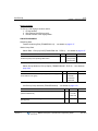
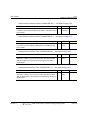
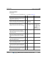
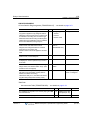
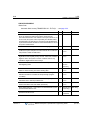
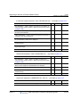
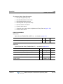
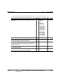
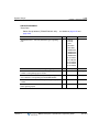
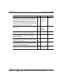
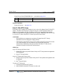
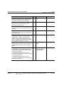
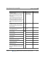
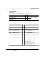
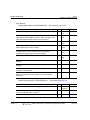
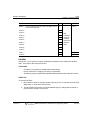
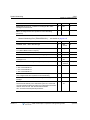
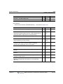
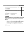
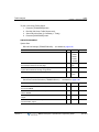
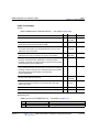
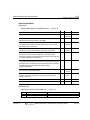
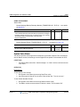
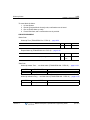
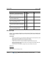
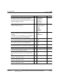
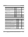
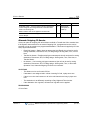
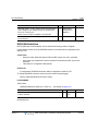
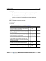
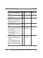
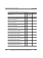
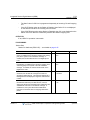
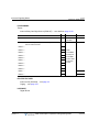
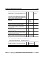
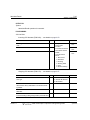
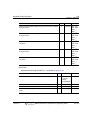
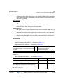
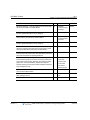
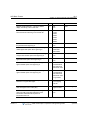
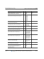
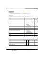
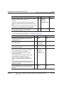
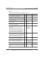
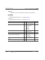
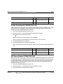
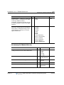
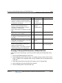
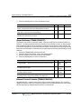
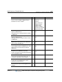
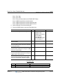
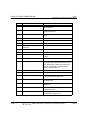
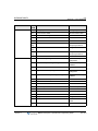
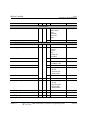
REVISION HISTORY
Release
Date
Documentation Changes
8SGDWHGSDUDPHWHUVLQ6\VWHP&DSDFLWLHVWDEOH
&KDQJHG3*0EXWWRQWRFRUUHFWQDPHVKRZQRQSKRQH
75$163*0
5HYLVHGYDULRXVV\VWHPIHDWXUHSURFHGXUHVLQFKDSWHU
Release 1.7
Page No.
WKURXJKRXW
ERRN
--
/DEHOHG1061HWZRUN0DQDJHPHQW6\VWHPVHFWLRQVQRW
DYDLODEOHDWWKLVWLPH
$GGHG2XWFDOO1RWLILFDWLRQIHDWXUH
$GGHG+RWHO0DQDJHPHQWFKDSWHU
%
5HPRYHGDOOUHIHUHQFHVWR3333RLQWWR3RLQW3URWRFRO
75$163*0LVQRWVXSSRUWHG
--
5HPRYHG7ZRZD\5HFRUGWR86%FRGHLVQRWVXSSRUWHG
--
,QLWLDO5HOHDVH
April 2012
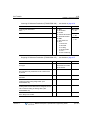
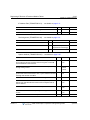
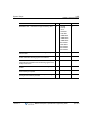
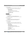
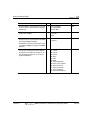
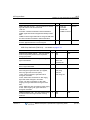
Contents
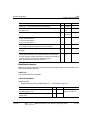
Chapter 1
Introduction
Manual Layout - - - - - - - - - - - - - - - - - - - - - - - - - - - - - - - - - - Organization - - - - - - - - - - - - - - - - - - - - - - - - - - - - - - - - - Feature Information - - - - - - - - - - - - - - - - - - - - - - - - - - - - System Capacities - - - - - - - - - - - - - - - - - - - - - - - - - - - - - - - Phones & Consoles Supported - - - - - - - - - - - - - - - - - - - - - - -
Chapter 2
1-1
1-1
1-1
1-2
1-4
Directory Number (DN)
Terms - - - - - - - - - - - - - - - - - - - - - - - - - - - - - - - - - - - - - - 2-1
Basic Features - - - - - - - - - - - - - - - - - - - - - - - - - - - - - - - - 2-2
Chapter 3
System Features
Account Code - - - - - - - - - - - - - - - - - - - - - - - - - - - - - - - - - - - 3-1
Alarm Signal/Door Bell - - - - - - - - - - - - - - - - - - - - - - - - - - - - - 3-3
Authorization Codes (Password) - - - - - - - - - - - - - - - - - - - - - - 3-5
Auto Call Release - - - - - - - - - - - - - - - - - - - - - - - - - - - - - - - - 3-6
Automatic Pause Insertion - - - - - - - - - - - - - - - - - - - - - - - - - - 3-7
Automatic Privacy/Branch Line - - - - - - - - - - - - - - - - - - - - - - - 3-8
Auto Service Mode Control - - - - - - - - - - - - - - - - - - - - - - - - - 3-10
Automatic System Daylight Savings Time - - - - - - - - - - - - - - - 3-12
Automatic System Time Synchronization - - - - - - - - - - - - - - - 3-13
Battery Back-up, Memory - - - - - - - - - - - - - - - - - - - - - - - - - - 3-14
Call Forward - - - - - - - - - - - - - - - - - - - - - - - - - - - - - - - - - - - 3-15
Call Forward, Pilot Hunt - - - - - - - - - - - - - - - - - - - - - - - - - - - 3-19
Call Forward, Preset - - - - - - - - - - - - - - - - - - - - - - - - - - - - - - 3-22
Call Park - - - - - - - - - - - - - - - - - - - - - - - - - - - - - - - - - - - - - - 3-24
Call Pick-Up - - - - - - - - - - - - - - - - - - - - - - - - - - - - - - - - - - - - 3-26
Directed Call Pick-Up - - - - - - - - - - - - - - - - - - - - - - - - - - 3-26
Group Call Pick-Up - - - - - - - - - - - - - - - - - - - - - - - - - - - - 3-28
Release 1.7
MBX IP Description / Operations & Programming Guide
April 2012
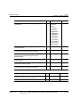
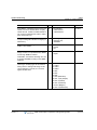
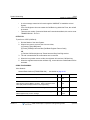
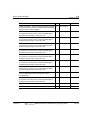
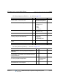
Contents
TOC-2
Call Transfer - - - - - - - - - - - - - - - - - - - - - - - - - - - - - - - - - - - Call Transfer, Station - - - - - - - - - - - - - - - - - - - - - - - - - - Call Transfer, CO/IP - - - - - - - - - - - - - - - - - - - - - - - - - - - CO/IP Access - - - - - - - - - - - - - - - - - - - - - - - - - - - - - - - - - - CO/IP Call Time Restriction - - - - - - - - - - - - - - - - - - - - - - - - CO/IP Call Warning Tone Timer - - - - - - - - - - - - - - - - - - - - - CO/IP Queuing - - - - - - - - - - - - - - - - - - - - - - - - - - - - - - - - - Conference - - - - - - - - - - - - - - - - - - - - - - - - - - - - - - - - - - - - Conference Room - - - - - - - - - - - - - - - - - - - - - - - - - - - - Multi-Party Voice Conference - - - - - - - - - - - - - - - - - - - - Consultation Conference - - - - - - - - - - - - - - - - - - - - - - - - Unsupervised Conference - - - - - - - - - - - - - - - - - - - - - - - Customer Site Name - - - - - - - - - - - - - - - - - - - - - - - - - - - - - Data Line Security - - - - - - - - - - - - - - - - - - - - - - - - - - - - - - - Delayed CO/IP Ring - - - - - - - - - - - - - - - - - - - - - - - - - - - - - - Delayed Auto Attendant - - - - - - - - - - - - - - - - - - - - - - - - - - - Diagnostic/Maintenance - - - - - - - - - - - - - - - - - - - - - - - - - - - Dial-By-Name - - - - - - - - - - - - - - - - - - - - - - - - - - - - - - - - - - Dial Pulse to Tone Switchover - - - - - - - - - - - - - - - - - - - - - - Dialing Restrictions - - - - - - - - - - - - - - - - - - - - - - - - - - - - - - Class of Service - - - - - - - - - - - - - - - - - - - - - - - - - - - - - - Day/Timed & Night Station COS - - - - - - - - - - - - - - - - - - Temporary Station COS/Lock - - - - - - - - - - - - - - - - - - - - Walking COS - - - - - - - - - - - - - - - - - - - - - - - - - - - - - - - - Differential Ring - - - - - - - - - - - - - - - - - - - - - - - - - - - - - - - - - Digit Conversion - - - - - - - - - - - - - - - - - - - - - - - - - - - - - - - - Do Not Disturb (DND) - - - - - - - - - - - - - - - - - - - - - - - - - - - - Door Open - - - - - - - - - - - - - - - - - - - - - - - - - - - - - - - - - - - - Door Phone - - - - - - - - - - - - - - - - - - - - - - - - - - - - - - - - - - - - Emergency Call/Emergency Alert - - - - - - - - - - - - - - - - - - - - Executive/Secretary by DN (Directory Number) - - - - - - - - - - Executive/Secretary by Exec/Sec Assignment - - - - - - - - - - - External Auto Attendant/Voice Mail - - - - - - - - - - - - - - - - - - - -
Release 1.7
MBX IP Description / Operations & Programming Guide
3-30
3-30
3-31
3-37
3-40
3-43
3-45
3-47
3-47
3-50
3-52
3-53
3-55
3-56
3-57
3-58
3-60
3-60
3-62
3-63
3-63
3-65
3-68
3-71
3-73
3-74
3-77
3-79
3-80
3-82
3-83
3-85
3-87
April 2012
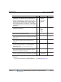
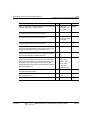
Contents
TOC-3
AA/VM Group - - - - - - - - - - - - - - - - - - - - - - - - - - - - - - - - 3-87
In-band (DTMF) Signaling - - - - - - - - - - - - - - - - - - - - - - - 3-90
SMDI (Simplified Msg Desk Interface) - - - - - - - - - - - - - - - 3-93
Flexible Numbering Plan - - - - - - - - - - - - - - - - - - - - - - - - - - - 3-97
Green Power Save - - - - - - - - - - - - - - - - - - - - - - - - - - - - - - - 3-99
Headset Compatibility - - - - - - - - - - - - - - - - - - - - - - - - - - - - - 3-99
Hold - - - - - - - - - - - - - - - - - - - - - - - - - - - - - - - - - - - - - - - - 3-101
Hold Recall - - - - - - - - - - - - - - - - - - - - - - - - - - - - - - - - - 3-102
Automatic Hold - - - - - - - - - - - - - - - - - - - - - - - - - - - - - - 3-104
Hot Desk - - - - - - - - - - - - - - - - - - - - - - - - - - - - - - - - - - - - - 3-106
In-Room Indication - - - - - - - - - - - - - - - - - - - - - - - - - - - - - - 3-108
IP Trans-coding - - - - - - - - - - - - - - - - - - - - - - - - - - - - - - - - 3-109
Last Number Redial (LNR) - - - - - - - - - - - - - - - - - - - - - - - - 3-110
Least Cost Routing (LCR) - - - - - - - - - - - - - - - - - - - - - - - - - 3-112
Linked Station Pairs/Group - - - - - - - - - - - - - - - - - - - - - - - - 3-114
Loud Bell Control (LBC) - - - - - - - - - - - - - - - - - - - - - - - - - - 3-116
Mobile Extension - - - - - - - - - - - - - - - - - - - - - - - - - - - - - - - 3-117
Multiple Language Selection - - - - - - - - - - - - - - - - - - - - - - - 3-120
Multiple Voice Mailbox Support - - - - - - - - - - - - - - - - - - - - - 3-122
Music-On-Hold (MOH) - - - - - - - - - - - - - - - - - - - - - - - - - - - 3-123
Network Management System (Future Feature) - - - - - - - - - 3-126
Network Security & Priority - - - - - - - - - - - - - - - - - - - - - - - - 3-127
One Digit Service - - - - - - - - - - - - - - - - - - - - - - - - - - - - - - - 3-128
Camp-On - - - - - - - - - - - - - - - - - - - - - - - - - - - - - - - - - - 3-128
Call Wait - - - - - - - - - - - - - - - - - - - - - - - - - - - - - - - - - - 3-129
Outcall Notification - - - - - - - - - - - - - - - - - - - - - - - - - - - - - - 3-131
Pre-defined & Custom Text Display Messages - - - - - - - - - - 3-134
Registering IP Devices & Fractional Module Tables - - - - - - - 3-137
Registration with MAC Address - - - - - - - - - - - - - - - - - - 3-137
Registration with ID/Password - - - - - - - - - - - - - - - - - - - 3-139
Registration with Station Number - - - - - - - - - - - - - - - - - 3-141
Remote Device Zone Management - - - - - - - - - - - - - - - - - - 3-143
Remote Services, Managed Net - - - - - - - - - - - - - - - - - - - - 3-144
Release 1.7
MBX IP Description / Operations & Programming Guide
April 2012
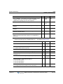
Contents
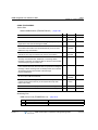
TOC-4
Revertible Ring - - - - - - - - - - - - - - - - - - - - - - - - - - - - - - - - Speed Dial - - - - - - - - - - - - - - - - - - - - - - - - - - - - - - - - - - - Speed Dial Pause Insertion - - - - - - - - - - - - - - - - - - - - - Station Speed Dial - - - - - - - - - - - - - - - - - - - - - - - - - - - System Speed Dial - - - - - - - - - - - - - - - - - - - - - - - - - - - Station Call Coverage - - - - - - - - - - - - - - - - - - - - - - - - - - - System Groups - - - - - - - - - - - - - - - - - - - - - - - - - - - - - - - - Station Group - - - - - - - - - - - - - - - - - - - - - - - - - - - - - - Greeting/Queuing Tone Service - - - - - - - - - - - - - - - - - - CCR Service with Queuing Announcement - - - - - - - - - - Forward Destination, Overflow Service - - - - - - - - - - - - - Pilot Hunt Group - - - - - - - - - - - - - - - - - - - - - - - - - - - - Pick Up Group - - - - - - - - - - - - - - - - - - - - - - - - - - - - - - Push To Talk (PTT) Group - - - - - - - - - - - - - - - - - - - - - Command Conference Group - - - - - - - - - - - - - - - - - - - Interphone Group - - - - - - - - - - - - - - - - - - - - - - - - - - - - Paging Group - - - - - - - - - - - - - - - - - - - - - - - - - - - - - - Station Message Detail Recording (SMDR) - - - - - - - - - - - - Call Cost Display - - - - - - - - - - - - - - - - - - - - - - - - - - - - SMDR Call Records - - - - - - - - - - - - - - - - - - - - - - - - - - System Admin Programming - - - - - - - - - - - - - - - - - - - - - - Keyset Administration - - - - - - - - - - - - - - - - - - - - - - - - - Multi-Level Admin Access - - - - - - - - - - - - - - - - - - - - - - This feature
Web Administration
- -is- -not
- - available
- - - - - - -at- -this
- - time
- - - -...- - - - - Web User Manual - - - - - - - - - - - - - - - - - - - - - - - - - - - System Networking - - - - - - - - - - -This
- -feature
- - -is -not-available
- - - -at -this- time
- - ...- - - Centralized Control T-NET (LM) - - - - - - - - - - - - - - - - - Distributed Control Network - - - - - - - - - - - - - - - - - - - - - Traffic Analysis - - - - - - - - - - - - - - - - - - - - - - - - - - - - - - - - System Time Management - - - - - - - - - - - - - - - - - - - - - - - - System Database Backup To USB - - - - - - - - - - - - - - - - - - Tenant Group - - - - - - - - - - - - - - - - - - - - - - - - - - - - - - - - - Universal Answer (UA) - - - - - - - - - - - - - - - - - - - - - - - - - - - -
Release 1.7
MBX IP Description / Operations & Programming Guide
3-145
3-146
3-146
3-147
3-150
3-153
3-153
3-154
3-162
3-168
3-173
3-178
3-182
3-183
3-184
3-185
3-186
3-187
3-187
3-189
3-194
3-194
3-195
3-197
3-199
3-200
3-200
3-202
3-250
3-252
3-255
3-255
3-257
April 2012
Contents
TOC-5
VMIB Integrated Auto Attd/Voice Mail - - - - - - - - - - - - - - - - VMIB - - - - - - - - - - - - - - - - - - - - - - - - - - - - - - - - - - - - VMIB-Auto Attendant - - - - - - - - - - - - - - - - - - - - - - - - - VMIB Voice Mail - - - - - - - - - - - - - - - - - - - - - - - - - - - - System Voice Memo - - - - - - - - - - - - - - - - - - - - - - - - - Wake-up Alarm - - - - - - - - - - - - - - - - - - - - - - - - - - - - - - - -
Chapter 4
3-258
3-258
3-258
3-261
3-280
3-283
Intercom
Direct Station Select/Busy Lamp Field (DSS/BLF) - - - - - - - - - - 4-1
Intercom Call (ICM Call) - - - - - - - - - - - - - - - - - - - - - - - - - - - - 4-2
Intercom Call Hold - - - - - - - - - - - - - - - - - - - - - - - - - - - - - - - - 4-4
Intercom Caller Controlled ICM Signaling - - - - - - - - - - - - - - - - 4-5
Intercom Lock-out - - - - - - - - - - - - - - - - - - - - - - - - - - - - - - - - 4-6
Intercom Step Call - - - - - - - - - - - - - - - - - - - - - - - - - - - - - - - - 4-7
Intercom Transfer - - - - - - - - - - - - - - - - - - - - - - - - - - - - - - - - - 4-8
INTRUSION - - - - - - - - - - - - - - - - - - - - - - - - - - - - - - - - - - - - 4-10
Message Wait/Call Back - - - - - - - - - - - - - - - - - - - - - - - - - - - 4-11
Station Message Wait/Call Back - - - - - - - - - - - - - - - - - - - 4-11
Message Wait Reminder Tone - - - - - - - - - - - - - - - - - - - - 4-14
Paging - - - - - - - - - - - - - - - - - - - - - - - - - - - - - - - - - - - - - - - 4-15
Internal/External & All Call Page - - - - - - - - - - - - - - - - - - - 4-15
Meet Me Page Answer - - - - - - - - - - - - - - - - - - - - - - - - - 4-17
VM Paging - - - - - - - - - - - - - - - - - - - - - - - - - - - - - - - - - - 4-20
Push-To-Talk Paging - - - - - - - - - - - - - - - - - - - - - - - - - - - - - 4-23
Chapter 5
CO/IP
Alternative Route Selection - - - - - - - - - - - - - - - - - - - - - - - - - - 5-1
Automatic Network Dialing - - - - - - - - - - - - - - - - - - - - - - - - - - 5-2
CO Group Access Code - - - - - - - - - - - - - - - - - - - - - - - - - - - - 5-3
CO Line Flash - - - - - - - - - - - - - - - - - - - - - - - - - - - - - - - - - - - 5-5
CO/IP Line Groups - - - - - - - - - - - - - - - - - - - - - - - - - - - - - - - - 5-7
CO Line Service - - - - - - - - - - - - - - - - - - - - - - - - - - - - - - - - - - 5-9
Incoming CO Line Option - - - - - - - - - - - - - - - - - - - - - - - - - 5-9
Outgoing CO Line Option - - - - - - - - - - - - - - - - - - - - - - - - 5-14
Alternate Incoming CO Service - - - - - - - - - - - - - - - - - - - 5-19
Release 1.7
MBX IP Description / Operations & Programming Guide
April 2012
Contents
TOC-6
Alternate Outgoing CO Service - - - - - - - - - - - - - - - - - - - Digit Sending Mode - - - - - - - - - - - - - - - - - - - - - - - - - - - CO COS - - - - - - - - - - - - - - - - - - - - - - - - - - - - - - - - - - - DID Name Service - - - - - - - - - - - - - - - - - - - - - - - - - - - - Incoming CO Line Holiday Service - - - - - - - - - - - - - - - - - DID/DISA Restriction - - - - - - - - - - - - - - - - - - - - - - - - - - CO/IP LINE PRESET FORWARD - - - - - - - - - - - - - - - - - - - - CO OWN CODE SERVICE - - - - - - - - - - - - - - - - - - - - - - - - - CO/IP Ring Assignment - - - - - - - - - - - - - - - - - - - - - - - - - - - CO Line Release Guard Time - - - - - - - - - - - - - - - - - - - - - - - CO Ring Detect - - - - - - - - - - - - - - - - - - - - - - - - - - - - - - - - - CO Transit Service - - - - - - - - - - - - - - - - - - - - - - - - - - - - - - Dial Pulse Signaling - - - - - - - - - - - - - - - - - - - - - - - - - - - - - - Direct Inward Dial (DID) - - - - - - - - - - - - - - - - - - - - - - - - - - - Direct Inward System Access (DISA) - - - - - - - - - - - - - - - - - - Dual Tone Multi-Frequency (DTMF) Signal Sending - - - - - - - H.323 Multi Route Service - - - - - - - - - - - - - - - - - - - - - - - - - Incoming Calling Line ID (ICLID) Call Routing - - - - - - - - - - - IP Trunking - - - - - - - - - - - - - - - - - - - - - - - - - - - - - - - - - - - - H.323 v4 Service - - - - - - - - - - - - - - - - - - - - - - - - - - - - - Session Initiation Protocol (SIP) Service - - - - - - - - - - - - - IP WAN Dialing After Answer - - - - - - - - - - - - - - - - - - - - - - - Integrated Service Digital Network (ISDN) - - - - - - - - - - - - - - ISDN Advice of Charge (AOC) - - - - - - - - - - - - - - - - - - - - Calling/Called Party Identification (CLIP/COLP) - - - - - - - Keypad Facility - - - - - - - - - - - - - - - - - - - - - - - - - - - - - - Multiple Subscriber Number (MSN) - - - - - - - - - - - - - - - - ISDN CLI - - - - - - - - - - - - - - - - - - - - - - - - - - - - - - - - - - - ISDN Supplementary Services - - - - - - - - - - - - - - - - - - - - - - ISDN Call Deflection - - - - - - - - - - - - - - - - - - - - - - - - - - - Representative CLI Service - - - - - - - - - - - - - - - - - - - - - - - - -
Chapter 6
5-25
5-28
5-28
5-29
5-31
5-34
5-35
5-36
5-37
5-41
5-42
5-42
5-44
5-45
5-50
5-55
5-55
5-57
5-59
5-59
5-61
5-62
5-64
5-64
5-68
5-69
5-71
5-73
5-76
5-76
5-77
Digital Phone
Auto Called Number Redial (ACNR) - - - - - - - - - - - - - - - - - - - - 6-2
Release 1.7
MBX IP Description / Operations & Programming Guide
April 2012
Contents
TOC-7
Auto Release of [Speaker] - - - - - - - - - - - - - - - - - - - - - - - - - - 6-4
Automatic Speaker Select - - - - - - - - - - - - - - - - - - - - - - - - - - - 6-4
Background Music (BGM) - - - - - - - - - - - - - - - - - - - - - - - - - - - 6-5
Call Log Display - - - - - - - - - - - - - - - - - - - - - - - - - - - - - - - - - - 6-6
CO Line Name Display - - - - - - - - - - - - - - - - - - - - - - - - - - - - - 6-8
One Time DND - - - - - - - - - - - - - - - - - - - - - - - - - - - - - - - - - - 6-9
Group Listening - - - - - - - - - - - - - - - - - - - - - - - - - - - - - - - - - 6-10
Intercom Signaling Mode - - - - - - - - - - - - - - - - - - - - - - - - - - 6-11
Mute - - - - - - - - - - - - - - - - - - - - - - - - - - - - - - - - - - - - - - - - - 6-13
Off-Hook Signaling - - - - - - - - - - - - - - - - - - - - - - - - - - - - - - - 6-14
On-Hook Dialing - - - - - - - - - - - - - - - - - - - - - - - - - - - - - - - - - 6-15
Prime Line Immediately/Delayed - - - - - - - - - - - - - - - - - - - - - 6-16
Differential Ring - - - - - - - - - - - - - - - - - - - - - - - - - - - - - - - - - 6-17
Saved Number Redial (SNR) - - - - - - - - - - - - - - - - - - - - - - - - 6-18
Speakerphone - - - - - - - - - - - - - - - - - - - - - - - - - - - - - - - - - - 6-19
Station Flexible Buttons - - - - - - - - - - - - - - - - - - - - - - - - - - - 6-21
Station Flexible LED Flash Rates - - - - - - - - - - - - - - - - - - - - - 6-22
Station ICLID Call Routing - - - - - - - - - - - - - - - - - - - - - - - - - 6-23
Station User Programming & Codes - - - - - - - - - - - - - - - - - - - 6-24
Two-Way Record - - - - - - - - - - - - - - - - - - - - - - - - - - - - - - - - 6-27
Answering Machine Emulation (AME) - - - - - - - - - - - - - - - - - 6-30
Voice Over - - - - - - - - - - - - - - - - - - - - - - - - - - - - - - - - - - - - 6-32
Chapter 7
Attendants
Attendant Group - - - - - - - - - - - - - - - - - - - - - - - - - - - - - - - - - - 7-1
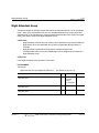
Night Attendant Group - - - - - - - - - - - - - - - - - - - - - - - - - - - - 7-10
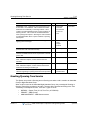
Greeting/Queuing Tone Service - - - - - - - - - - - - - - - - - - - - - - 7-14
CCR Service for Attendant Queuing Annoucement - - - - - - - - 7-19
Forward Destination, Overflow Service - - - - - - - - - - - - - - - - - 7-25
Attendant Recall - - - - - - - - - - - - - - - - - - - - - - - - - - - - - - - - - 7-29
Attendant Station Program Codes - - - - - - - - - - - - - - - - - - - - 7-32
Attendant Call/Queuing - - - - - - - - - - - - - - - - - - - - - - - - - - - - 7-36
Day/Night/Timed Ring Mode - - - - - - - - - - - - - - - - - - - - - - - - 7-37
DSS/DLS Consoles - - - - - - - - - - - - - - - - - - - - - - - - - - - - - - 7-40
Release 1.7
MBX IP Description / Operations & Programming Guide
April 2012
Contents
TOC-8
EZ-Attendant - - - - - - - - - - - - - - - - - - - - - - - - - - - - - - - - - - - System Clock Set - - - - - - - - - - - - - - - - - - - - - - - - - - - - - - - USB Upgrade - - - - - - - - - - - - - - - - - - - - - - - - - - - - - - - - - - USB DB Up/Download From/To USB - - - - - - - - - - - - - - - - - -
Chapter 8
7-41
7-42
7-43
7-45
Single Line Telephone
Broker Call - - - - - - - - - - - - - - - - - - - - - - - - - - - - - - - - - - - - - - 8-1
Hook-Flash Mode - - - - - - - - - - - - - - - - - - - - - - - - - - - - - - - - - 8-2
Howler Tone - - - - - - - - - - - - - - - - - - - - - - - - - - - - - - - - - - - - - 8-3
SLT Message Wait Indication - - - - - - - - - - - - - - - - - - - - - - - - - 8-4
SLT Name Registration - - - - - - - - - - - - - - - - - - - - - - - - - - - - - 8-5
Chapter 9
SIP Phone
SIP Terminal Registration - - - - - - - - - - - - - - - - - - - - - - - - - - - - 9-1
SIP Name Registration - - - - - - - - - - - - - - - - - - - - - - - - - - - - - - 9-2
SIP Placing Calls - - - - - - - - - - - - - - - - - - - - - - - - - - - - - - - - - - 9-2
SIP Call Pick-Up - - - - - - - - - - - - - - - - - - - - - - - - - - - - - - - - - - 9-3
SIP Hold Call - - - - - - - - - - - - - - - - - - - - - - - - - - - - - - - - - - - - - 9-3
SIP Transfer Call - - - - - - - - - - - - - - - - - - - - - - - - - - - - - - - - - - 9-3
SIP Call Forward - - - - - - - - - - - - - - - - - - - - - - - - - - - - - - - - - - 9-4
SIP Do Not Disturb (DND) - - - - - - - - - - - - - - - - - - - - - - - - - - - 9-4
SIP 3-Party Conference - - - - - - - - - - - - - - - - - - - - - - - - - - - - - 9-5
SIP Call Wait/Broker Call - - - - - - - - - - - - - - - - - - - - - - - - - - - - 9-5
SIP SMS - - - - - - - - - - - - - - - - - - - - - - - - - - - - - - - - - - - - - - - - 9-5
SIP Voice Mail Notification - - - - - - - - - - - - - - - - - - - - - - - - - - - 9-6
SIP Video Call - - - - - - - - - - - - - - - - - - - - - - - - - - - - - - - - - - - - 9-6
Chapter 10
ACD (Automatic Call Distribution)
ACD Basic Feature - - - - - - - - - - - - - - - - - - - - - - - - - - - - - - - 10-1
ACD Group Service Status - - - - - - - - - - - - - - - - - - - - - - - - - - 10-9
ACD Call Distribution by Priority - - - - - - - - - - - - - - - - - - - - - 10-16
ACD Call Queuing Service - - - - - - - - - - - - - - - - - - - - - - - - - 10-21
CCR Service During ACD Announcement - - - - - - - - - - - - - - 10-28
ACD Agent State - - - - - - - - - - - - - - - - - - - - - - - - - - - - - - - - 10-33
ACD Agent Log-in / Log-out Default Setting - - - - - - - - - - - - - 10-39
Release 1.7
MBX IP Description / Operations & Programming Guide
April 2012
Contents
TOC-9
ACD Call Indication - - - - - - - - - - - - - - - - - - - - - - - - - - - - - 10-44
ACD Group Supervisor Functions - - - - - - - - - - - - - - - - - - - 10-50
ACD Group Call Traffic - - - - - - - - - - - - - - - - - - - - - - - - - - - 10-58
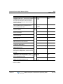
Appendix A
System Programming Tables
Initialization - - - - - - - - - - - - - - - - - - - - - - - - - - - - - - - - - - - - - A-1
Program Menu Structure - - - - - - - - - - - - - - - - - - - - - - - - - - - - A-2
Administration Menu Table - - - - - - - - - - - - - - - - - - - - - - - A-2
S/W Upgrade - - - - - - - - - - - - - - - - - - - - - - - - - - - - - - - - - A-6
System Management - - - - - - - - - - - - - - - - - - - - - - - - - - - A-6
Station Admin Programming - - - - - - - - - - - - - - - - - - - - - - - - - A-7
LCD & Button Functions - - - - - - - - - - - - - - - - - - - - - - - - - A-7
Alphanumeric Data Entries - - - - - - - - - - - - - - - - - - - - - - - A-7
Required Data Entries - - - - - - - - - - - - - - - - - - - - - - - - - - - A-7
Data Entry Mode - - - - - - - - - - - - - - - - - - - - - - - - - - - - - - - - - A-7
Procedures for Data Entry - - - - - - - - - - - - - - - - - - - - - - - - A-8
PRE-PROGRAMMED DATA - TRANS/PGM Codes 100 to 108 A-8
Location Program (TRANS/PGM 100) - - - - - - - - - - - - - - - - A-8
Slot Assignment (TRANS/PGM 101) - - - - - - - - - - - - - - - - A-11
Logical Slot Assignment (TRANS/PGM 103) - - - - - - - - - - A-11
DECT/IP Phone/SIP Phone Port Assignment (TRANS/PGM 104)
A-12
IP Phone/Phontage Registration Table (TRANS/PGM 106) A-12
DTIM/SLTM Registration Table (TRANS/PGM 107) - - - - - A-13
IP Address Plan (TRANS/PGM 108) - - - - - - - - - - - - - - - - A-14
System Information (TRANS/PGM 109) - - - - - - - - - - - - - A-14
NUMBERING PLAN DATA - TRANS/PGM Codes 110 to 116 A-15
Numbering Plan Type (TRANS/PGM 110) - - - - - - - - - - - - A-15
System Numbering Plan (TRANS/PGM 111) - - - - - - - - - - A-15
Flexible Station Number (TRANS/PGM 112) - - - - - - - - - - A-16
FEATURE NUMBERING PLAN (TRANS/PGM 113) - - - - - - - A-17
CO Group Access Code (TRANS/PGM 114) - - - - - - - - - - A-21
Station Group Number (TRANS/PGM 115) - - - - - - - - - - - A-22
Release 1.7
MBX IP Description / Operations & Programming Guide
April 2012
Contents
TOC-10
ACD Group Number (TRANS/PGM 118) - - - - - - - - - - - STATION DATA - TRANS/PGM Codes 120-152 - - - - - - - - - Station Type (TRANS/PGM 120) - - - - - - - - - - - - - - - - - Station Port Attributes (TRANS/PGM 121-124) - - - - - - - Station Flexible Button Assignment (TRANS/PGM 126) - Station Number Information (TRANS/PGM 130) - - - - - - Station Number Attributes - TRANS/PGM 131-135 - - - - Station Class of Service (TRANS/PGM 137) - - - - - - - - - Station Auto Attributes (TRANS/PGM 138) - - - - - - - - - - Station Preset Call Forward (TRANS/PGM 142) - - - - - - Station Call Forward (TRANS/PGM 143) - - - - - - - - - - - Station VMIB Attribute (TRANS/PGM 145) - - - - - - - - - - Station Mobile Phone Attribute (TRANS/PGM 146) - - - - CO/IP Group Access (TRANS/PGM 150) - - - - - - - - - - - Internal Page Group Access (TRANS/PGM 151) - - - - - - Command Group Access (TRANS/PGM 152) - - - - - - - - CO LINE DATA - TRANS/PGM 160-181 - - - - - - - - - - - - - - CO Attribute I, II, III - TRANS/PGM 160-162 - - - - - - - - - CO CID Attributes (TRANS/PGM 163) - - - - - - - - - - - - - CO Incoming Attribute I, II - TRANS/PGM 165-166 - - - - CO Ring Assignment (TRANS/PGM 167) - - - - - - - - - - - Incoming CO Normal/DISA Attributes (TRANS/PGM 168)
CO Incoming Alternate Destination (TRANS/PGM 169) - CO Outgoing Attributes I (TRANS/PGM 170) - - - - - - - - CO Outgoing Attributes II (TRANS/PGM 171) - - - - - - - - CO Outgoing Alternate Destination (TRANS/PGM 173) - CO Outgoing Inter-Digit Timer (TRANS/PGM 174) - - - - CO DTMF Sending Delay Timer (TRANS/PGM 175) - - - CO COS Assignment (TRANS/PGM 177) - - - - - - - - - - - CO to CO Transfer Attributes (TRANS/PGM 179) - - - - - CO Group Access Code Attribute (TRANS/PGM 180) - - Alternate Ring Assignment (TRANS/PGM 181) - - - - - - - SYSTEM GROUP DATA - TRANS/PGM 200-215 - - - - - - - - -
Release 1.7
MBX IP Description / Operations & Programming Guide
A-22
A-23
A-23
A-24
A-29
A-31
A-31
A-37
A-38
A-39
A-40
A-40
A-42
A-43
A-43
A-44
A-44
A-44
A-48
A-48
A-51
A-52
A-53
A-54
A-57
A-57
A-58
A-59
A-60
A-60
A-61
A-63
A-63
April 2012
Contents
TOC-11
Station Group (TRANS/PGM 200) - - - - - - - - - - - - - - - - - A-64
Station Group Greeting/Queuing Attributes (TRANS/PGM 201) A-65
Station Group Attributes (TRANS/PGM 202) - - - - - - - - - - A-68
Voice Mail Group Attributes (TRANS/PGM 203) - - - - - - - - A-69
Pick Up Group (TRANS/PGM 204) - - - - - - - - - - - - - - - - - A-70
Page Group (TRANS/PGM 205) - - - - - - - - - - - - - - - - - - - A-71
Command Call Group (TRANS/PGM 206) - - - - - - - - - - - - A-72
PTT Group (TRANS/PGM 208) - - - - - - - - - - - - - - - - - - - A-73
Interphone Group (TRANS/PGM 209) - - - - - - - - - - - - - - - A-73
Pilot Hunt Group (TRANS/PGM 210) - - - - - - - - - - - - - - - A-74
Pilot Hunt Group Forward Attribute (TRANS/PGM 211) - - A-75
ACD Group (TRANS/PGM 212) - - - - - - - - - - - - - - - - - - - A-76
ACD Group Attribute I (TRANS/PGM 213) - - - - - - - - - - - - A-77
ACD Group Attribute II (TRANS/PGM 214) - - - - - - - - - - - A-79
ACD Group Announcement (TRANS/PGM 215) - - - - - - - - A-81
SYSTEM DATA - TRANS/PGM 220-242 - - - - - - - - - - - - - - - A-82
System Timers I (TRANS/PGM 220) - - - - - - - - - - - - - - - - A-83
System Timers II (TRANS/PGM 221) - - - - - - - - - - - - - - - A-84
System Timers II (TRANS/PGM 222) - - - - - - - - - - - - - - - A-84
System Attributes (TRANS/PGM 223) - - - - - - - - - - - - - - - A-85
System Password (TRANS/PGM 226) - - - - - - - - - - - - - - A-86
Alarm Attributes (TRANS/PGM 227) - - - - - - - - - - - - - - - - A-87
External Control Contacts (TRANS/PGM 228) - - - - - - - - - A-87
Music Sources (TRANS/PGM 229) - - - - - - - - - - - - - - - - - A-88
RS-232 Port Settings (TRANS/PGM 230) - - - - - - - - - - - - A-89
Serial Port Function Selections (TRANS/PGM 231) - - - - - A-90
SMDR Attributes (TRANS/PGM 232) - - - - - - - - - - - - - - - A-91
System Date, Time (TRANS/PGM 233) - - - - - - - - - - - - - - A-94
Button LED Flash Rate (TRANS/PGM 234) - - - - - - - - - - - A-95
ISDN PPP Web Admin Attributes (TRANS/PGM 235) - - - - A-99
Mobile Attributes (TRANS/PGM 236) - - - - - - - - - - - - - - A-100
One Digit Service Attributes (TRANS/PGM 237) - - - - - - A-101
Release 1.7
MBX IP Description / Operations & Programming Guide
April 2012
Contents
TOC-12
Dummy Dial Tone Digit (TRANS/PGM 240) - - - - - - - - - - A-101
Executive/Secretary Assign (TRANS/PGM 241) - - - - - - - A-102
Executive-Executive Access (TRANS/PGM 242) - - - - - - - A-103
TABLES DATA - TRANS/PGM 250-269 - - - - - - - - - - - - - - - - A-103
Toll Tables (TRANS/PGM 250) - - - - - - - - - - - - - - - - - - - A-103
Digit Conversion Tables (TRANS/PGM 251) - - - - - - - - - - A-104
Digit Conversion Options (TRANS/PGM 252) - - - - - - - - - A-106
Time Table Attributes (TRANS/PGM 253) - - - - - - - - - - - - A-107
Weekly Time Table (TRANS/PGM 254) - - - - - - - - - - - - - A-108
LCR Time Table Attributes (TRANS/PGM 255) - - - - - - - - A-109
Holiday Time Table (TRANS/PGM 256) - - - - - - - - - - - - - A-110
System Speed Table (TRANS/PGM 257) - - - - - - - - - - - - A-110
Emergency Code Table Attributes (TRANS/PGM 258) - - - A-111
Announcement Table (TRANS/PGM 259) - - - - - - - - - - - - A-111
Customer Call Routing Table (TRANS/PGM 260) - - - - - - A-112
Customer Call Routing Table (TRANS/PGM 262) - - - - - - A-113
CLI Conversion Table (TRANS/PGM 263) - - - - - - - - - - - A-114
CLI Conversion Table (TRANS/PGM 264) - - - - - - - - - - - A-114
Ring Table (TRANS/PGM 265) - - - - - - - - - - - - - - - - - - - A-115
Ring Freq/Cadence Table (TRANS/PGM 266) - - - - - - - - A-116
Voice Mail Dialing Table (TRANS/PGM 269) - - - - - - - - - - A-116
TENANTS DATA - TRANS/PGM 270-290 - - - - - - - - - - - - - - A-117
Attendant Group - TRANS/PGM 270-272 - - - - - - - - - - - - A-118
Night Attendant Group - TRANS/PGM 275-277 - - - - - - - - A-123
Tenant Attributes - TRANS/PGM 280-281 - - - - - - - - - - - A-127
Tenant Group Access (TRANS/PGM 283) - - - - - - - - - - - A-130
CO Call Restriction - TRANS/PGM 284-285 - - - - - - - - - - A-130
Call Prefix Table - TRANS/PGM 286-288 - - - - - - - - - - - - A-132
Tenant Tone Table (TRANS/PGM 290) - - - - - - - - - - - - - A-133
BOARD DATA - TRANS/PGM 300-310 - - - - - - - - - - - - - - - - A-138
ISDN Board Attribute (TRANS/PGM 300) - - - - - - - - - - - - A-138
ISDN Board - Clock Priority (TRANS/PGM 301) - - - - - - - A-139
IPP Board Attribute (TRANS/PGM 305) - - - - - - - - - - - - - A-140
Release 1.7
MBX IP Description / Operations & Programming Guide
April 2012
Contents
TOC-13
Reset Board (TRANS/PGM 310) - - - - - - - - - - - - - - - - - A-140
NETWORKING DATA - TRANS/PGM 320-321 - - - - - - - - - - A-141
Net Basic Attribute (TRANS/PGM 320) - - - - - - - - - - - - - A-141
Net Numbering Plan Table (TRANS/PGM 321) - - - - - - - A-142
TNET, CENTRALIZED NETWORKING..-. TRANS/PGM 330-335 - - me
A-143
is ti
h
t
t
le a
TNET Basic Attributes
ilab (TRANS/PGM 330) - - - - - - - - - - A-143
a
v
ot a
TNET CM Attributes
(TRANS/PGM 331) - - - - - - - - - - - - A-143
is n
e
r
u
t
a
FoPSTN
Attributes (TRANS/PGM 333) - - - - - - - - - - - - - A-144
s fe
T hi
Board TNET Attributes (TRANS/PGM 334) - - - - - - - - - - A-145
IP Phone TNET Attributes (TRANS/PGM 335) - - - - - - - - A-145
H.323 DATA - TRANS/PGM 360-363 - - - - - - - - - - - - - - - - - A-146
H.323 Routing Attributes (TRANS/PGM 360) - - - - - - - - - A-146
H.323 Call Setup Info (TRANS/PGM 361) - - - - - - - - - - - A-146
H.323 Incoming Attributes (TRANS/PGM 362) - - - - - - - - A-147
GK Setup Info (TRANS/PGM 363) - - - - - - - - - - - - - - - - A-148
GAIN & CADENCE CONTROL - TRANS/PGM 400-440 - - - A-149
DKT RX Gain (TRANS/PGM 400) - - - - - - - - - - - - - - - - - A-149
SLT RX Gain (TRANS/PGM 401) - - - - - - - - - - - - - - - - - A-149
DECT RX Gain (TRANS/PGM 402) - - - - - - - - - - - - - - - A-150
IP-Phone RX Gain (TRANS/PGM 403) - - - - - - - - - - - - - A-150
Analog CO RX Gain (TRANS/PGM 404) - - - - - - - - - - - - A-151
Digital CO RX Gain (TRANS/PGM 405) - - - - - - - - - - - - A-152
VMIB RX Gain (TRANS/PGM 406) - - - - - - - - - - - - - - - - A-152
External Page RX Gain (TRANS/PGM 407) - - - - - - - - - - A-153
DSP RX Gain (TRANS/PGM 415) - - - - - - - - - - - - - - - - A-154
RTP RX Gain (TRANS/PGM 420-426) - - - - - - - - - - - - - A-154
RTP RX Gain (TRANS/PGM 430-436) - - - - - - - - - - - - - A-157
SLT Ring Cadence (TRANS/PGM 440) - - - - - - - - - - - - - A-160
ACNR Tone Cadence (TRANS/PGM 441) - - - - - - - - - - - A-162
DB INITIALIZATION (TRANS/PGM 499) - - - - - - - - - - - - - - A-162
Release 1.7
MBX IP Description / Operations & Programming Guide
April 2012
Contents
TOC-14
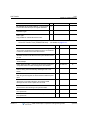
Appendix B
Hotel Management
- - - - - - - - - - - - - - - - - - - - - - - - System Capacity and License B-1
Hotel Service Type - - - - - - - - - - - - - - - - - - - - - - - - - - - - - - - B-3
Multiple Front Desks - - - - - - - - - - - - - - - - - - - - - - - - - - - - - - B-7
Check In - - - - - - - - - - - - - - - - - - - - - - - - - - - - - - - - - - - - - - - B-7
Check Out - - - - - - - - - - - - - - - - - - - - - - - - - - - - - - - - - - - - - - B-9
Call Barring - - - - - - - - - - - - - - - - - - - - - - - - - - - - - - - - - - - - B-11
CO Call Barring (Room Cut) - - - - - - - - - - - - - - - - - - - - - B-11
ICM Call Barring - - - - - - - - - - - - - - - - - - - - - - - - - - - - - - B-12
One-Time CO Call Use - - - - - - - - - - - - - - - - - - - - - - - - - B-13
Room Setting - - - - - - - - - - - - - - - - - - - - - - - - - - - - - - - - - - B-14
Wake-Up Registration/Cancellation - - - - - - - - - - - - - - - - B-14
Do No Disturb Registration/Cancellation - - - - - - - - - - - - - B-17
Message Wait Registration/Cancellation - - - - - - - - - - - - - B-18
Bath Alarm - - - - - - - - - - - - - - - - - - - - - - - - - - - - - - - - - B-20
Register/Change Authorization Code - - - - - - - - - - - - - - - B-21
Register/Change Prepaid Money - - - - - - - - - - - - - - - - - - B-22
Room Swapping - - - - - - - - - - - - - - - - - - - - - - - - - - - - - - - - B-23
Maid Status - - - - - - - - - - - - - - - - - - - - - - - - - - - - - - - - - - - - B-23
Room Charge/Status Print - - - - - - - - - - - - - - - - - - - - - - - - - B-25
Room Charge Display/Print - - - - - - - - - - - - - - - - - - - - - - B-25
Print Room Status through RS-232C - - - - - - - - - - - - - - - B-29
Deleting Service Station's SMDR Record - - - - - - - - - - - - B-30
Room Rate - - - - - - - - - - - - - - - - - - - - - - - - - - - - - - - - - - - - B-30
Room Rate Register/Assign - - - - - - - - - - - - - - - - - - - - - B-30
Fee For Part Time - - - - - - - - - - - - - - - - - - - - - - - - - - - - B-31
Register Bar and Mini-bar Charge - - - - - - - - - - - - - - - - - B-34
Call Rate - - - - - - - - - - - - - - - - - - - - - - - - - - - - - - - - - - - - - - B-36
Call Charge Rate Register/Assign - - - - - - - - - - - - - - - - - B-36
Register Hotel Name - - - - - - - - - - - - - - - - - - - - - - - - - - - - - B-38
Set Call Forward - - - - - - - - - - - - - - - - - - - - - - - - - - - - - - - - B-38
Additional Tax Fields - - - - - - - - - - - - - - - - - - - - - - - - - - - - - B-39
Release 1.7
MBX IP Description / Operations & Programming Guide
April 2012
Contents
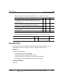
TOC-15
Guest Name/Info Display - - - - - - - - - - - - - - - - - - - - - - - - - Dial One Digit Service - - - - - - - - - - - - - - - - - - - - - - - - - - - - Room Monitor / Baby Listening - - - - - - - - - - - - - - - - - - - - - Call Answer Recognition (not available in U.S.) - - - - - - - - - - Form Feed Button - - - - - - - - - - - - - - - - - - - - - - - - - - - - - - VIP Guest Call - - - - - - - - - - - - - - - - - - - - - - - - - - - - - - - - - VIP Guest Wake-Up Call - - - - - - - - - - - - - - - - - - - - - - - - - - Fidelio Hotel Feature (optional with license) - - - - - - - - - - - - -
Appendix C
B-40
B-40
B-41
B-42
B-44
B-44
B-45
B-46
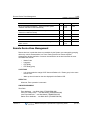
Quick Reference
DATABASE INDEX - - - - - - - - - - - - - - - - - - - - - - - - - - - - - - - C-1
DEFAULT NUMBERING PLAN - - - - - - - - - - - - - - - - - - - - - - - C-8
FIXED FUNCTION/USER PROGRAM CODES - - - - - - - - - - - C-17
DEFAULT VALUES - - - - - - - - - - - - - - - - - - - - - - - - - - - - - - C-21
USER ENTRY GUIDES - - - - - - - - - - - - - - - - - - - - - - - - - - C-105
Alphanumeric Entry Chart - - - - - - - - - - - - - - - - - - - - - - C-105
Alternate Alphanumeric Entry Chart - - - - - - - - - - - - - - - C-106
Index
Release 1.7
MBX IP Description / Operations & Programming Guide
April 2012
Contents
Release 1.7
TOC-16
MBX IP Description / Operations & Programming Guide
April 2012
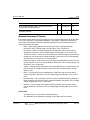
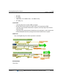
Manual Layout
1-1
Chapter 1: Introduction
Chapter 1
Introduction
This chapter describes the manual and provides a table that shows the system capacities
available in the MBX IP System Software.
Manual Layout
Organization
Features are arranged alphabetically in seven different major groupings that follow two basic
chapters (1 - Introduction) and (2 - Directory Number):
3) System features
4) Intercom features
5) CO/IP features
6) Digital Phone features
7) Attendant features
8) Single Line Telephone features
9) SIP features
This book also includes three appendices that contain specific information: System
Programming tables (Appendix A), Hotel Management (Appendix B), and Quick Reference
tables (Appendix C).
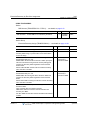
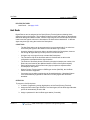
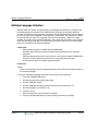
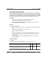
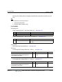
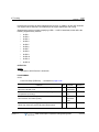
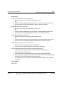
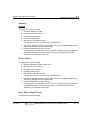
Feature Information
Each section is an alphabetical listing of features with the description and operation of each.
The structure is divided into 6 parts when they apply:
•
•
•
•
•
•
Release 1.7
The description below the chapter title explains the nature of those features.
CONDITIONS: explains known interactions and constraints related to the feature.
OPERATIONS: gives detailed step-by-step operation of the feature for Digital Phones
and SLTs.
PROGRAMMING: lists database entries that may be required for proper feature
operation.
RELATED FEATURES: lists related information to aid in understanding the feature.
HARDWARE: lists hardware required for proper feature operation.
MBX IP Description / Operations & Programming Guide
April 2012
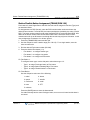
System Capacities
1-2
Chapter 1: Introduction
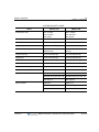
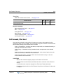
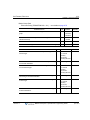
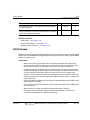
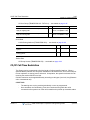
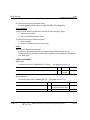
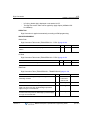
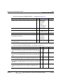
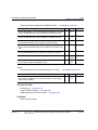
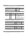
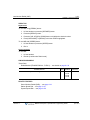
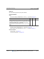
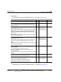
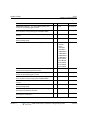
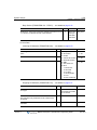
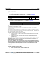
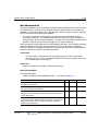
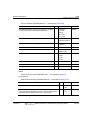
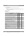
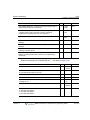
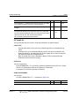
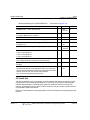
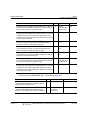
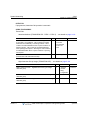
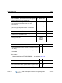
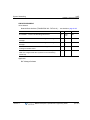
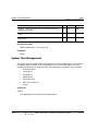
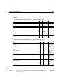
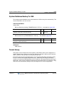
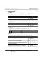
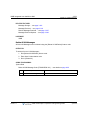
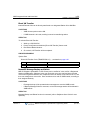
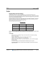
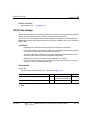
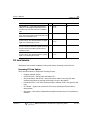
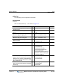
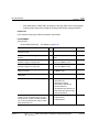
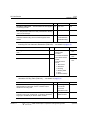
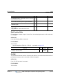
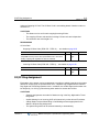
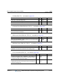
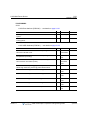
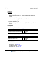
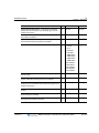
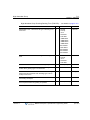
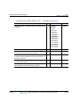
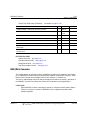
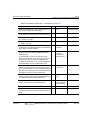
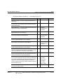
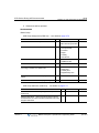
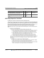
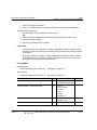
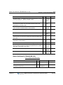
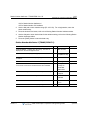
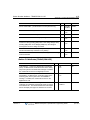
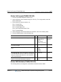
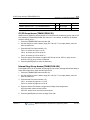
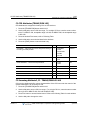
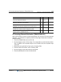
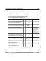
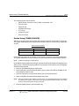
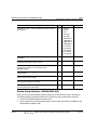
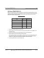
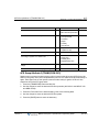
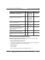
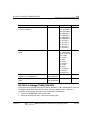
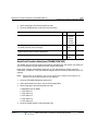
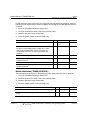
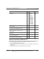
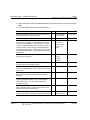
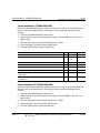
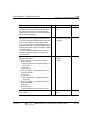
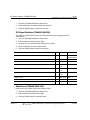
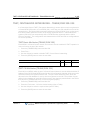
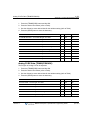
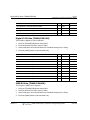
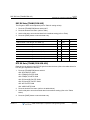
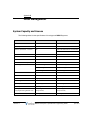
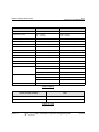
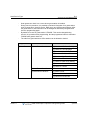
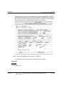
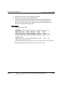
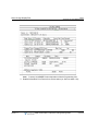
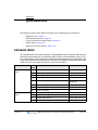
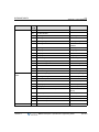
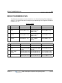
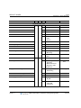
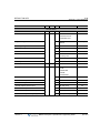
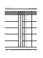
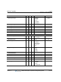
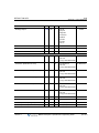
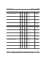
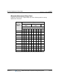
System Capacities
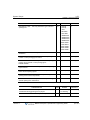
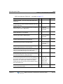
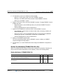
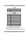
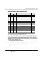
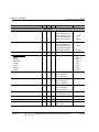
The MBX IP Series is available in the configurations shown in the table below:
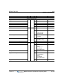
SYSTEM CAPACITY CHART
Items
MBX IP-100
MBX IP-300
Rack No.
2
3
Slot No. per Rack
6
6
Total Port (Extension + CO line)
200
414 (if IP Phone/DECT
Cordless phone not included)
Number of extension Port
120
324
Number of extension
180 (Ext 120 + DN 60)
648 (Ext 324 + DN 324)
Number of CO Line
80
240
Number of Tenant Group
5
9
Numbering Plan
Extension: 8 Digits
Extension: 8 Digits
Feature: 8 Digits
Feature: 8 Digits
Trunk: 8 Digits
Trunk: 8 Digits
Attendant
5/Tenant
5/Tenant
DSS/BLF Console
5
5
Conference Members
3 Groups/13 Members
3 Groups/13 Members
Internal Page Zone
15
30
System Speed Dial
1000
2000
(32 digits)
(32 digits)
50 (32 digits)
50 (32 digits)
Station Speed Dial
Call Log (Outgoing/Incoming/Missed Call) 100 (32 digits) (Not protected)
100 (32 digits) (Not protected)
Save Number Redial(SNR)
1 (32 digits)
1 (32 digits)
Number of SMDR Records
5000
5000
Release 1.7
MBX IP Description / Operations & Programming Guide
April 2012
System Capacities
1-3
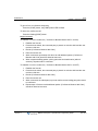
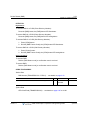
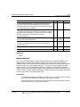
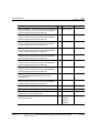
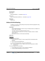
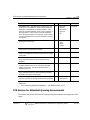
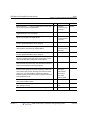
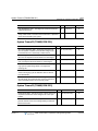
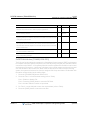
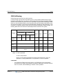
Chapter 1: Introduction
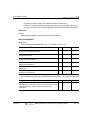
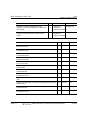
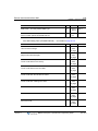
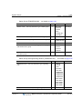
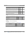
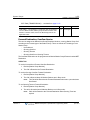
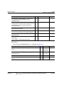
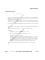
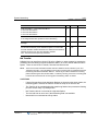
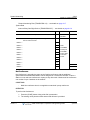
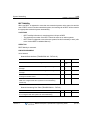
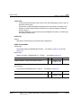
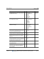
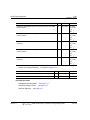
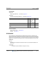
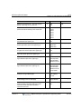
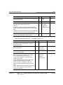
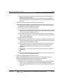
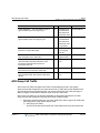
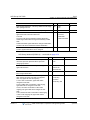
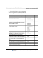
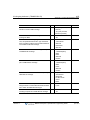
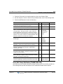
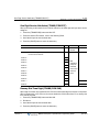
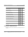
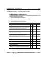
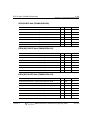
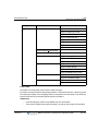
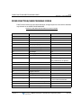
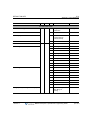
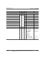
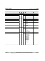
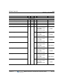
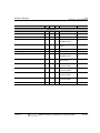
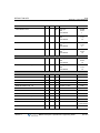
SYSTEM CAPACITY CHART
Items
MBX IP-100
MBX IP-300
Authorization Code
Max. 12 Digits
180: Extension
400: System
Max. 12 Digits
648: Extension
800: System
CO Group No
24
72
Station Group
50 member/Group)
50 member/Group
Pickup Group
20 (100 member/Group)
50 (100 member/Group)
Command Call Group
10 (12 member + 1
initiator/Group)
10 (12 member + 1 initiator
/Group)
Interphone Group
10 (10 member/Group)
10 (10 member/Group)
Page Group
15 (50 member/Group)
30 (50 member/Group)
PTT Group
10 (50 member/Group)
10 (50 member/Group)
Conference Room
9
9
Number of Hot Desk Agent
60
324
Station Name Information
16 Characters
16 Characters
Digit Restriction
COS: 16
COS: 16
Allow/Deny Entry per COS: 100
Allow/Deny Entry per COS: 100
Max. Digit: 16
Max. Digit: 16
Table No: 5
Table No: 5
Number of Digit: 16
Number of Digit: 16
300 per 1 table
300 per 1 table
Digit Translation
Release 1.7
MBX IP Description / Operations & Programming Guide
April 2012
Phones & Consoles Supported
1-4
Chapter 1: Introduction
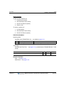
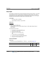
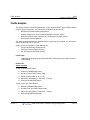
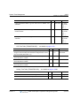
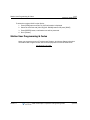
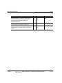
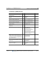
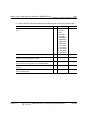
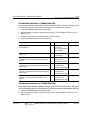
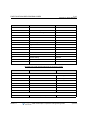
Phones & Consoles Supported
These are the phone models supported by the MBX IP systems:
•
5000-series SIP Phones
•
DECT Cordless Phones
•
Edge 700
•
- 8/24-Button Digital Phones
Edge 8000
-
8012/8024 IP Phones
•
- 8312/8324 IP Phones
SBX IP
•
- 8/24-Button Digital Phones
STS
•
- 24-Buton Digital Phones
Triad & infinite
•
- 8/12/24-Button Digital Phones
Vodavi/Uniphone
•
- 8/30-Button-Digital Phones
CONSOLES
- Edge 100: 12/24/DSS Consoles
(The SHIFT button does not function on all phone types.)
- IBX 24/48/64 DSS Consoles
(The SHFT function does not operate on the DSS consoles.)
Release 1.7
MBX IP Description / Operations & Programming Guide
April 2012
2-1
Chapter 2: Directory Number (DN)
Chapter 2
Directory Number (DN)
Directory Number (DN) is the telephone number for internal users, which can be used
exclusively by only one station or can be shared by multiple stations.
Terms
TYPES OF DN
• SADN-NORMAL : Single-Assign Directory Number (SADN) that can be used by only one station.
• SADN-HOTDESK : Single-Assign Directory Number (SADN) for Hot Desk Usage.
• MADN: Multi-Assign Directory Number (MADN) that can be used by one or multiple stations.
CATEGORY OF DN
• My DN is assigned on flexible button 1 by default. It can be moved to a different flexible button but
cannot be deleted.
• My-DN (M-DN): each station must have at least one unique number that cannot be used by another
station (minimum requirement, automatically assigned by board configuration). Otherwise, it is not
possible to make outgoing calls or receive incoming calls.My DN is assigned on flexible button 1 by
default. It can be moved to a different flexible button but cannot be deleted.
• Sub-DN (S-DN): station can have more numbers but M-DN. All numbers except M-DN are called
S-DN.
NOTE:
S-DN can be shared by other stations if it is MADN type.
PRIME DN
• If multiple numbers are used by a station, one DN can be selected to have higher priority over
others. When only one number exists, it becomes P-DN, which will be seized first for outgoing calls,
answered first if there's are multiple incoming calls, and used for idle status display for DND,
Forward, Absent Message and so on that can be set independently for each DN.
RELATED PROGRAMMING
System Data
Numbering Plan, Station Number (TRANS/PGM 112) … see details on page A-16
Release 1.7
MBX IP Description / Operations & Programming Guide
April 2012
2-2
Chapter 2: Directory Number (DN)
Station Data
Station Number Type (TRANS/PGM 130 - Flex 1) … see details on page A-31
MADN Member (TRANS/PGM 130 - Flex 2) … see details on page A-31
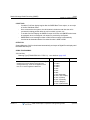
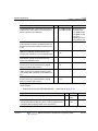
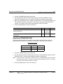
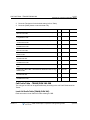
Prime Number Button (TRANS/PGM 123 - Flex 1) … see details on page A-26
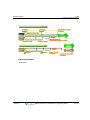
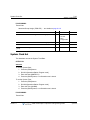
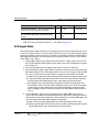
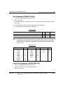
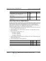
TRANS/PGM 123
BTN
PRIME NUMBER BTN -- among My-DN and several Sub-DNs
which are assigned to station flex buttons, determines the
first-seized DN when the user initiates a call. If prime button is not
set of invalid, the system scans sequentially from flexible button 1
to flexible Button 48 and take the unused and valid flexible button
as prime button NOTE: DN buttons of associated DSS box cannot
be a prime number button.
1
RANGE
01-48
DEFAULT
01
Basic Features
To use DN features, or to receive incoming calls or make outgoing calls, DN must be
programmed on a Flex button, except in the case of an analog phone (does not have flex
buttons). One DN is stored in each station by default, which is M-DN. If there is no DN button
at all, it is not possible to call a number or get a call from others.
Making Calls
When making outgoing calls, a Station User can select a DN number either by pressing
the appropriate DN flex button, by going off-hook using the handset, or by dialing while the
phone is on-hook.
P-DN is seized automatically if the DN button is not explicitly pressed as in the case of
going off-hook or on-hook dialing. However, if the P-DN is busy at that time (P-DN can be
shared by other stations), the first idle DN button is selected in the order of button number
(button 1 first, button 2 second, etc.).
Once a DN is selected for an outgoing call, the tenant group number, calling station
number, CLI, COS and other DN-related information are applied for the duration of the
call. For example, if a different DN is selected for two outgoing calls, it is possible to have
different tenant groups or COS for each call.
Receiving Calls
A physical station can receive additional calls showing on DN buttons, or through other
available DN numbers that are stored in that station, even while on a call. However, if the
DN is in use, it is not possible to receive a call through that DN number.
Release 1.7
MBX IP Description / Operations & Programming Guide
April 2012
2-3
Chapter 2: Directory Number (DN)
the status of a physical station and each DN is maintained independantly.
If the Station is idle, the normal ring will be provided. Otherwise, off-hook signaling is
activated. The Station User can answer an incoming call by pressing the flashing DN flex
button, or by going off-hook without selecting a DN flex button. If there are multiple
incoming calls at the same time, going off-hook allows the user to seize P-DN if it is
ringing, or to seize first ringing DN in the order of button number (btn 1 first, btn 2 second).
NOTE:
Even when there are incoming calls at a station, the User can make an outgoing call by
pressing an idle DN button and dialing the called party number.
P-DN (PrimeDN) Feature
P-DN is automatically seized first when a station user goes off-hook or dials while on-hook
when receiving or making calls. P-DN can be either M-DN or S-DN. If P-DN is not
assigned explicitly, the first DN button becomes P-DN in the order of button number.
The same DN can be used as P-DN for multiple stations. If the state of shared P-DN is
changed in this case, the status of P-DN will be updated to all the stations that have the
shared P-DN. For example, DND, call forward, and other DN-based status notifications
will be displayed at all same DN-programmed stations.
LED of DN Button
LED states of DN buttons are as follows:
•
Green ON: DN being used by my station
•
Red ON: DN being used by another station
•
Amber flash: Held DN
•
Green Flash: Ringing DN
•
Red Flash: DN in DND status or DN in Call Forward
DN Tenant Group/COS
Each DN can be programmed with its own Tenant group or COS information. So, Tenant
group and COS can be different for each call depending on the DN used for the calls.
If a station has DN buttons with different tenant groups, the station can make and receive
calls using the different tenant groups.
Additionally, if the DN buttons have different COS, a station can have different COS
according to the DN button selected.
Branch Line
When a station is using a MADN-type DN, other stations cannot access the same DN.
However, if a branch line option is set to the DN, another Station can access the busy DN
interrupting its call and establishing a conference call for all users.
Release 1.7
MBX IP Description / Operations & Programming Guide
April 2012
2-4
Chapter 2: Directory Number (DN)
Incoming Ring Option
When multiple stations have the same DN button, each station can have a different ring
delay option.
•
Immediate Ring: Ring signal is sent to station with no delay.
•
Delayed Ring: Ring signal is sent to station after the programmed delay.
•
No ring: Ring signal is not sent to station, but only LED flashes.
When the DN receives an incoming call, the DN button LED will flash Red regardless of
the ring delay option. However, the LCD of a station modified to display the incoming call
after it receives a ring signal can be automatically answered just by going off-hook.
However, before the station receives a ring signal, the incoming DN call cannot be
answered automatically by going off-hook, but the station user should press the flashing
DN button manually.
Access Option
When a station has multiple DN buttons, each DN button can have a different access
option.
•
All Call: No restriction.
•
Dial After Seizure: No restriction about incoming ringing, but when making outgoing
calls with this button, user should seize the DN by pressing this button even if this
button is assigned to prime number button.
•
Incoming Only: Outgoing call is not possible with this button.
When there is incoming call to a DN, the DN button LED will flash in red color regardless
of the ring delay option. However, the LCD of station is changed to display the incoming
call after it receives ring signal and the call can be answered automatically just by going
off-hook. However, before the station receives ring signal, the incoming DN call cannot be
answered automatically by going off-hook, but the station user should press the flashing
DN button manually.
Release 1.7
MBX IP Description / Operations & Programming Guide
April 2012
Account Code
3-1
Chapter 3: System Features
Chapter 3
System Features
This chapter provides detailed information covering description and operation of the numerous
features available in the MBX IP System Software.
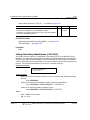
Account Code
Station users may enter a non-verified variable length (up to 12 digits) identifier for tracking
specific calls. The identifier or “Account Code” is output as part of the Station Message Detail
Record (SMDR) for the call.
CONDITIONS
-
If an Authorization Code is entered as the Account Code, the SMDR record will show
the station number or the bin number for a System Authorization Code rather than the
user entered Authorization Code for security purposes.
OPERATION
Digital Phone
To assign a Flex button for {ACCOUNT CODE} operation:
Press [TRANS/PGM] + {FLEX} + Button Feature Type (1) + {Account Code Feature Code}
+ {Account Code} + + [HOLD/SAVE]
*
To enter an Account Code using an {ACCOUNT CODE} button prior to placing a call when
account code is not entered in the button:
1. Lift the handset
2. Press the {account code} button.
3. Dial the Account Code (1 to 12 digits).
*
4. Press ; Intercom dial tone is heard.
5. Place the CO/IP call as normal.
Release 1.7
MBX IP Description / Operations & Programming Guide
April 2012
Account Code
3-2
Chapter 3: System Features
Using the programmed {ACCOUNT CODE} button prior to making a call:
1. Lift the handset.
2. Press the {account code} button; Intercom dial tone is heard.
3. Place the CO/IP call as normal.
Using an {ACCOUNT CODE} button during a call:
1. Press the {account code} button; CO line is held and the station hears dial tone.
2. Dial the Account Code (1 to 12 digits).
*
3. Press ; Station is re-connected with CO line.
Single Line Phone
To enter an Account Code prior to placing a call:
1. Lift the handset.
2. Dial the {Account Code Feature Code}.
3. Dial the Account Code (1 to 12 digits).
*
4. Press .
5. Place the CO/IP call as normal.
To enter an Account Code during a call:
1. Press for Hook-switch.
2. Dial {Account Code Feature Code}
3. Dial the Account Code (1 to 12 digits).
*
4. Press .
ADMIN PROGRAMMING
Numbering
Feature Numbering Plan (TRANS/PGM 113) … page A-17
RELATED FEATURES
Authorization Codes (Password) … see page 3-5
Station Message Detail Recording (SMDR) … see page 3-187
Station Flexible Buttons … see page 6-21
Release 1.7
MBX IP Description / Operations & Programming Guide
April 2012
Alarm Signal/Door Bell
3-3
Chapter 3: System Features
Alarm Signal/Door Bell
The system can be configured to recognize the status of an external contact (normally open or
closed). The system will signal the assigned station when the contact activates. This capability
is commonly employed to provide remote Alarm or Door Bell signals to the user.
A station receives the Alarm Signal, either as a single tone burst repeated at 1-minute intervals
or a continuous tone. The Alarm Signal may be terminated at the User's phone by dialing the
Alarm Stop code, or pressing the {ALARM STOP} button if assigned. To rearm the Alarm
function, the alarm condition must be cleared and the Alarm signal terminated.
When used as a Door Bell, assigned stations receive an Alarm Signal each time the external
contact is activated; reset is not required.
CONDITIONS
-
The Alarm contacts must be "dry", no voltage or current source connected.
-
A station with LCD assigned to receive Alarm/Door Bell signals will show "ALARM" as
appropriate.
-
If alarm is active during station busy, mute ring will be served to assigned station, and
then after conversation, when station go to idle, the alarm signal will be sent to
assigned station again.
-
Assigned stations can be changed using Alarm Assign. (TRANS/PGM121-Flex12)
-
Only Stations assigned with Alarm ring can terminate the alarm signal.
-
IP Phone and normal digital Phone stations can be assigned as alarm stations.
-
In signal mode, station will return alarm ringing again if an assigned station user does
not reset the alarm signal prior to the station returning to idle.
-
When the alarm is ringing, the alarm signal must be reset so phone operation will be
fully functional (fixed or flex buttons do not operate and the user cannot hear the dial
tone during alarm ringing).
OPERATION
System
At detection of contact operation, the Alarm/Door Bell signal is sent to assigned station.
Digital Phone
To assign a Flex button as an {ALARM STOP} button:
Press [TRANS/PGM/] + {FLEX} + Button Feature Type(1) + {Sys Alarm Reset Feature
Code} + [HOLD/SAVE]
Release 1.7
MBX IP Description / Operations & Programming Guide
April 2012
Alarm Signal/Door Bell
3-4
Chapter 3: System Features
To terminate an Alarm Signal while idle:
Dial the {Sys Alarm Reset Feature Code}; a confirmation tone is received and the Alarm
Signal is terminated.
OR
Press the programmed {ALARM STOP} Flex button.
NOTE:
If the alarm condition is cleared, the system will automatically rearm the alarm
monitoring.
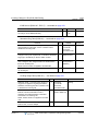
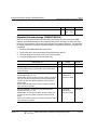
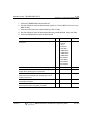
ADMIN PROGRAMMING
Station Data
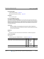
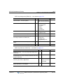
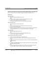
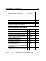
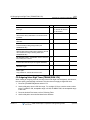
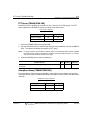
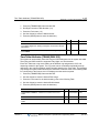
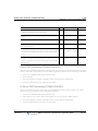
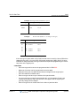
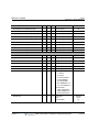
Alarm (TRANS/PGM 121 - FLEX12) … see details on page A-24
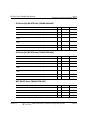
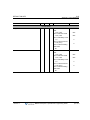
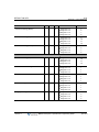
TRANS/PGM 121
ALARM -- enable to receive system alarm signal.
BTN
RANGE
DEFAULT
12
1-3
1
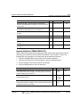
System
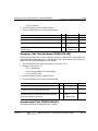
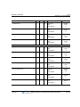
Alarm (TRANS/PGM 121 - FLEX12) … see details on page A-87
TRANS/PGM 227
BTN
RANGE
DEFAULT
ALARM ENABLE -- enables the external contact monitoring circuitry.
1
0: Off
1: On
Off
ALARM CONTACT TYPE -- establishes the contact state that will
activate the Alarm, close or open.
2
0: Open
1:Close
Open
ALARM MODE -- the contact can be designated to function as a
doorbell instead of an alarm.
3
0: Bell
1: Alarm
Alarm
ALARM SIGNAL MODE -- the assigned stations will receive a
Repeating signal or single burst (ONCE) of the alarm tone.
4
0: Once
Repeat
1: Repeat
RELATED FEATURES
Door Open … see page 3-79
HARDWARE
Digital Phone
External contact connected to Alarm input of MPB, refer to MBX IP Hardware &
Installation Manual.
Release 1.7
MBX IP Description / Operations & Programming Guide
April 2012
Authorization Codes (Password)
3-5
Chapter 3: System Features
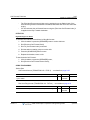
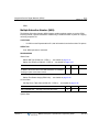
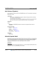
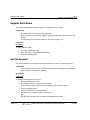
Authorization Codes (Password)
An Authorization Code is tied to a DN, and provides a means to control access to Walking COS,
or DISA and may be required for outgoing CO/IP Lines based on the configuration of the
database. When users dial a valid Authorization Code, the system invokes the Station COS.
The Station Authorization Code includes the associated station number and the assigned code.
A Station Authorization Code is specifically related to a given station and intended for a single
user.
The Administrator and Attendants are permitted to assign any Authorization code including
codes for another station. Normal users may only assign the Station Authorization code for the
specific station.
CONDITIONS
-
A user may enter an Authorization Code from any station to place a CO/IP call using
Walking COS.
-
An Authorization code may include any dial pad digit except
* and #.
OPERATION
Digital Phone
To assign a Station Authorization Code:
1. Press the [TRANS/PGM] button.
2. Dial 34 {Authorization Code Program}.
3. Dial the Authorization Code (1-12 digits).
4. Dial
* or press the [HOLD/SAVE] button to save.
Single Line Phone
To assign a Station Authorization code:
1. Lift the handset.
2. Dial [SLT Program Mode Entry code}.
3. Dial Station User Program code 34.
4. Dial Authorization Code (1-12 digits).
*
5. Dial .
Release 1.7
MBX IP Description / Operations & Programming Guide
April 2012
Auto Call Release
3-6
Chapter 3: System Features
System Attendant
To assign an Authorization Code:
1. Press the [TRANS/PGM] button.
2. Dial Attendant Station Program Code 033.
3. Dial station number or range of stations. If one (1) station is to be programmed, enter
that station number twice.
4. Dial the Authorization Code.
5. Press the [HOLD/SAVE] button.
ADMIN PROGRAMMING
Station Data
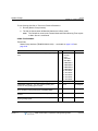
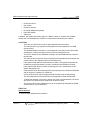
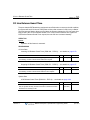
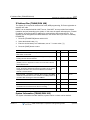
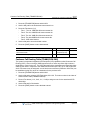
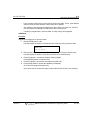
Password (TRANS/PGM 131 - FLEX 4) … see details on page A-32
TRANS/PGM 131
BTN
RANGE
PASSWORD -- Password is employed to control access to the
system resources and facilities. Walking COS, CO/IP Group access
DISA callers and certain Call Forward types may require the input of
a valid password.
4
0: Disable
1: Enable
DEFAULT
Disable
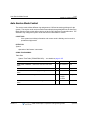
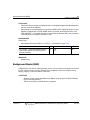
Auto Call Release
Intercom calls (except Hands-free Ring Back) will be released automatically if the called party
does not answer during the pre-set time.
CONDITIONS
-
When the handset is used to place a call, the user will receive an error tone for 30
seconds followed by 30 seconds of Howler tone and the station is placed in a fault
mode. If on-hook dialing is used, the station will receive an error tone for one (1)
second and the phone will return to idle automatically.
OPERATION
System
Auto Call Release of Intercom calls: If a station places an intercom call and the called
station does not answer in the Intercom Call Release Time, the call is terminated and the
calling user receives an error tone.
Release 1.7
MBX IP Description / Operations & Programming Guide
April 2012
Automatic Pause Insertion
3-7
Chapter 3: System Features
ADMIN PROGRAMMING
Table Data
System Ring Table: Normal Call Ring … use Web Admin (TRANS/PGM 265) see details
on page A-115
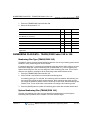
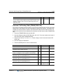
Howler Tone (TRANS/PGM 121 - FLEX 7)… see details on page A-24
TRANS/PGM 121
HOWLING TONE -- sets Anonymous Call Restrict service.
BTN
7
RANGE
0: Off
1: On
DEFAULT
On
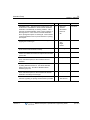
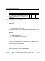
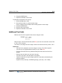
Automatic Pause Insertion
In addition to a manually entered Pause, the system will automatically pause dialing to allow for
potential connection delays. The pause will be inserted when any of the following occur:
•
Flash is encountered in a Speed Dial number.
•
Pulse to Tone Switchover is encountered in a Speed Dial or Redial number.
•
Connect message is received on an ISDN Line.
CONDITIONS
-
An automatically inserted pause is not counted as a digit in a Speed Dial number.
-
The LCD of the Digital Phone will show a "P" when a pause is encountered.
-
When the System inserts a Pause, “P” indication is not shown.
OPERATION
System
The system automatically pauses dialing after an appropriate event (as listed above).
RELATED FEATURES
Auto Called Number Redial (ACNR) … see page 6-2
Last Number Redial (LNR) … see page 3-110
Dial Pulse to Tone Switchover … see page 3-62
Release 1.7
MBX IP Description / Operations & Programming Guide
April 2012
Automatic Privacy/Branch Line
3-8
Chapter 3: System Features
Automatic Privacy/Branch Line
Privacy is insured in all communications on the system. If desired, the customer may elect to
disable the Automatic Privacy feature, allowing an uninvited station to join in an existing
external conversation. In such a case, a conference is established. The Privacy feature
restricts the intrusion/call-wait/camp-on/OHVA at a busy station, while the Branch Line can
restrict a conference call by pressing {DN} button in use.
CONDITIONS
-
With Automatic Privacy disabled, privacy is still assured on all intercom and
conference calls.
-
Only one station can intrude on an active call.
-
An intrusion tone can be provided to the call indicating another station has accessed
the line.
OPERATION
Digital Phone
To intrude into a call when Privacy is disabled:
Make a call to busy station and then press the appropriate code for
intrusion/call-wait/camp-on/OHVA when receiving busy tone.
To change privacy mode in conversation:
Press the {DND} button during a conversation.
To intrude in a call when Branch Line is enabled:
Press a busy (lit steady) {DN} button, the user is connected to the call with the existing
internal station user.
ADMIN PROGRAMMING
Station Data
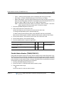
Branch Line (TRANS/PGM 134 - FLEX 10) … see details on page A-34
TRANS/PGM 134
BRANCH/BRIDGE LINE -- Set branch/bridge line feature.
Branch: Conference call by pressing {DN} button in use.
Bridge: Bridge call by pressing {DN} button in use.
Bridge (Softphone): Auto bridge if Phontage/UC Client’s IP bridge is
enabled.
Release 1.7
BTN
10
RANGE
DEFAULT
0: Off
1: On
Off
MBX IP Description / Operations & Programming Guide
April 2012
Automatic Privacy/Branch Line
3-9
Chapter 3: System Features
Auto Privacy (TRANS/PGM 134 - FLEX 11) … see details on page A-34
TRANS/PGM 134
BTN RANGE
AUTO PRIVACY -- Enables auto privacy feature (to restrict the
intrusion/call-wait/camp-on/OHVA in busy station)
11
0: Off
1: On
DEFAULT
Off
System Data
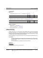
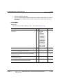
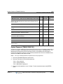
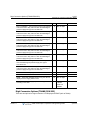
Intercom Busy One-Digit Service (TRANS/PGM 237) … see details on page A-101
TRANS/PGM 237
BTN
RANGE
0:Disable
1:Enable
DEFAULT
STEP CALL -- determines if Step Call is enabled or disabled.
1
Disable
DIGIT 1 -- when accessing a busy tone, user may dial for one of
the one-touch services.
2
DIGIT 2 --
3
DIGIT 3 --
4
DIGIT 4 --
5
DIGIT 5 --
6
DIGIT 6 --
7
DIGIT 7 --
8
DIGIT 8 --
9
DIGIT 9 --
10
DIGIT 0 --
11
DIGIT * --
12
Call Wait
DIGIT # --
13
Voice-Over
0: N/A
0: N/A
1: Call-Back
2: Camp On
3: Call Wait
4: Voice Over
5: Intrusion
6: Hunt
RELATED FEATURES
Multi-Party Voice Conference … see page 3-50
Station Flexible Buttons … see page 6-21
Release 1.7
MBX IP Description / Operations & Programming Guide
April 2012
Auto Service Mode Control
3-10
Chapter 3: System Features
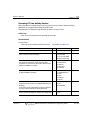
Auto Service Mode Control
The service mode defines different ring assignments, COS and answering privileges for the
system. The service mode can be controlled automatically through definitions in the Auto Ring
Mode Selection Table, which defines the time of day for Day, Night and Timed shift modes. The
Attendant may change the system mode selection from automatic to manual.
CONDITIONS
-
If the system has Holiday information and current mode is Holiday, service mode is
operated as Night mode
OPERATION
System
Operation of this feature is automatic.
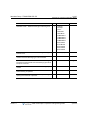
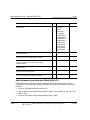
ADMIN PROGRAMMING
Table Data
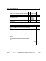
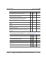
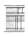
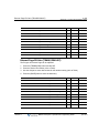
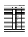
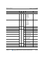
System Time Table (TRANS/PGM 253) … see details on page A-107
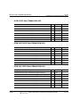
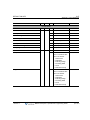
TRANS/PGM 253
Release 1.7
BTN
RANGE
DEFAULT
TIME ZONE COMMENT-- defines the comment of the Time
Table.
1
32 characters none
SYSTEM TIME ZONE -- defines the Time Zone of the Time Table
2
0-73
0: Sys Time
DAYLIGHT SAVINGS -- defines Daylight Saving Time of Time
Table.
3
On/Off
Off
RING MODE -- defines the ring mode of Time Table.
4
0: Day
1: Night
2: Timed
0: Day
AUTO RING MODE -- defines the Auto Ring mode of the Time
Table.
5
On/Off
Off
MBX IP Description / Operations & Programming Guide
April 2012
Auto Service Mode Control
3-11
Chapter 3: System Features
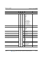
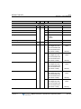
Weekly Time Table (TRANS/PGM 254) … see details on page A-108
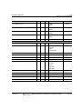
TRANS/PGM 254
BTN
RANGE
DEFAULT
Monday DAY/NIGHT/TIMED ring mode start times and TIMED mode
end times.
1
0000-2359
Day: 9:00
Nite: 18:00
TDS: _-_
TDE: _-_
Tuesday DAY/NIGHT/TIMED ring mode start times and TIMED
mode end times.
2
0000-2359
Day: 9:00
Nite: 18:00
TDS: _-_
TDE: _-_
Wednesday DAY/NIGHT/TIMED ring mode start times and TIMED
mode end times.
3
0000-2359
Day: 9:00
Nite: 18:00
TDS: _-_
TDE: _-_
Thursday DAY/NIGHT/TIMED ring mode start times and TIMED
mode end times.
4
0000-2359
Day: 9:00
Nite: 18:00
TDS: _-_
TDE: _-_
Friday DAY/NIGHT/TIMED ring mode start times and TIMED mode
end times.
5
0000-2359
Day: 9:00
Nite: 18:00
TDS: _-_
TDE: _-_
Saturday DAY/NIGHT/TIMED ring mode start times and TIMED
mode end times.
6
0000-2359
Day: 9:00
Nite: 18:00
TDS: _-_
TDE: _-_
Sunday DAY/NIGHT/TIMED ring mode start times and TIMED mode
end times.
7
0000-2359
Day: 9:00
Nite: 18:00
TDS: _-_
TDE: _-_
Holiday Time Table (TRANS/PGM 256) … see details on page A-110
TRANS/PGM 256
BTN
RANGE
DEFAULT
CALENDAR TYPE -- Defines Calendar Type for Holiday Table.
1
Lunar/Gregorian
Gregorian
HOLIDAY DATE -- Defines Holiday Date for Holiday Table.
2
MM/DD
None
Release 1.7
MBX IP Description / Operations & Programming Guide
April 2012
Automatic System Daylight Savings Time
3-12
Chapter 3: System Features
RELATED FEATURES
Direct Inward System Access (DISA) … see page 5-50
Day/Night/Timed Ring Mode … see page 7-37
CO Ring Assignment … see page 5-37
LBC (Loud Bell Control) … see page 3-116
Dialing Restrictions … see page 3-63
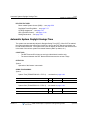
Automatic System Daylight Savings Time
The system can automatically adjust for Daylight Saving Time (DST). When DST is enabled,
the system will adjust the system time forward one hour at the DST Start time and back one
hour at the DST End time. The system time is sent for display to all devices and terminals and
is the basis of the various system time-based features (Wake-up Alarm, etc.).
CONDITIONS
-
The DST Start and End times are set by the Web Admin interface only.
-
The interval between the DST Start and End times must be at least 7 days.
OPERATION
System
Operation of this feature is automatic.
ADMIN PROGRAMMING
System
System Time (TRANS/PGM 233 - FLEX 1) … see details on page A-94
TRANS/PGM 233
SYSTEM TIME/DATE -- sets the system time.
BTN
1
RANGE
HH:MM
DEFAULT
-
System Date (TRANS/PGM 233 - FLEX 2) … see details on page A-94
TRANS/PGM 233
SYSTEM TIME/DATE -- sets the system date.
Release 1.7
BTN
2
RANGE
MMDDYY
DEFAULT
-
MBX IP Description / Operations & Programming Guide
April 2012
Automatic System Time Synchronization
3-13
Chapter 3: System Features
DST Enable (TRANS/PGM 233 - FLEX 3) … see details on page A-94
DST Start & End Time … use Web Admin (TRANS/PGM 233)
TRANS/PGM 233
BTN
RANGE
DEFAULT
DST START TIME -- the DST start time.
Web See DST Table 2nd Sunday of March
Only
at 2:00 AM
DST END TIME -- the DST end time.
Web See DST Table 1st Sunday of
Only
November at 2:00 AM
RELATED FEATURES
Auto Service Mode Control … see page 3-10
Automatic System Time Synchronization … see page 3-13
System Clock Set … see page 7-42
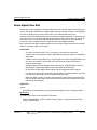
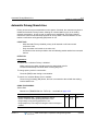
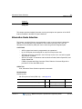
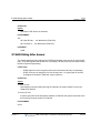
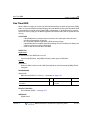
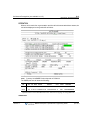
Automatic System Time Synchronization
When enabled, the system automatically determines and sets the time of day employing
Network Time Protocol (NTP) or ISDN time messages. When using NTP, the system requests
and receives GMT time at ten-minute intervals from the specified NTP time server. This feature
allows the System Time to synchronize with the NTP time server automatically. If the time
deviates more than two seconds, the system clock is adjusted to match the NTP server.
When using ISDN, the system receives the time of day in ISDN messages and automatically
adjusts the time if the system time deviates from the ISDN time.
CONDITIONS
-
NTP packets are expected over UDP port 123; verify the port is open and available.
-
A secondary NTP server address can be defined should the first server not respond.
-
If set, the system adjusts for the local time zone assigned in the system as the
Standard System Time as well as Daylight Savings Time (DST).
OPERATION
System
Operation of this feature is automatic.
Release 1.7
MBX IP Description / Operations & Programming Guide
April 2012
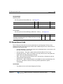
Battery Back-up, Memory
3-14
Chapter 3: System Features
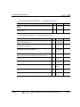
ADMIN PROGRAMMING
System
Network Time/Date (TRANS/PGM 223 – FLEX 5) … see details on page A-85
TRANS/PGM 223
BTN
NETWORK DATE/TIME USE -- If set to ON, the System updates the
Date & Time with Network Date & Time when the System Date &
Time is different.
5
RANGE
0: Off
1: On
DEFAULT
0: Off
NTP Active … use Web Admin (TRANS/PGM 233)
NTP Sever Address … use Web Admin (TRANS/PGM 233)
Standard System Time, Local Time Zone … use Web Admin (TRANS/PGM 233)
RELATED FEATURES
Auto Service Mode Control … see page 3-10
Automatic System Daylight Savings Time … see page 3-12
System Clock Set … see page 7-42
Battery Back-up, Memory
The system database is protected from power-loss by a long life (10-year) lithium dry cell
battery. Should local power fail, the battery will maintain the system memory and proper
operation of the system clock.
CONDITIONS
-
The Initialization switch must be in the ON position to enable Memory Battery
Back-up. Otherwise, should power fail, the system will initialize the database on
power-up. Refer to the MBX IP Hardware and Installation Guide for more details.
-
The Lithium battery is not field-replaceable.
OPERATION
System
When enabled, operation is automatic.
Release 1.7
MBX IP Description / Operations & Programming Guide
April 2012
Call Forward
3-15
Chapter 3: System Features
Call Forward
User may have selected incoming calls re-route to other stations (local or networked), station
groups, the VMIIB, or over a system CO/IP line (Off-Net).
The user selects the type and condition under which calls will forward by entering a Call
Forward code as follows:
•
Code 0, Remote Call Forward – forwards all calls to the station, except recalls,
activated from a remote station, Call Forward, Follow-me.
•
Code 1, Unconditional – all calls to the station, except recalls, are forwarded internally
or externally immediately upon receipt.
•
Code 2, Busy – if the station is busy, forwards all calls, except recalls, to the selected
station.
•
Code 3, No Answer – forwards all calls, except recalls, to the selected station when
the station does not answer within the No Answer timer.
•
Code 4, Busy/No Answer – forwards calls if the selected station is busy or does not
answer within the No Answer timer.
CONDITIONS
Release 1.7
-
A station receiving a forwarded call can transfer the call to the forwarding station.
-
A station, denied the use of Call Forward, will receive an error tone in response to
attempts to activate Call Forward.
-
A forwarded intercom call will signal the receiving station in Tone Signaling mode,
regardless of the Intercom Signaling Mode at the station.
-
Attempting activation of Call Forward will automatically deactivate any activated
Display Text Message (Active Call Back or Queue requests do not cancel).
-
When Call Forward is active, a Station can make outgoing calls (internal or external).
-
For CO/IP calls, when Call Forward is manually activated, it will override any Preset
Call Forward assigned for the station or CO/IP line
-
Call Forward status is maintained in the System’s non-volatile memory for protection
from power outage.
-
Off-Net Call Forward of incoming CO/IP calls is essentially an automated DISA call,
which will establish an Unsupervised Conference; such calls are subject to the
conditions of a DISA call and Unsupervised Conference and may require entry of an
Authorization Code.
-
Off-Net Forward calls are not answered until the system completes dialing of the
external call. The call, internal or external, is then connected to the Off-Premise call.
MBX IP Description / Operations & Programming Guide
April 2012
Call Forward
3-16
Chapter 3: System Features
-
An unlimited number of stations may be set-up in a Call Forward chain, forwarding
calls from one station to the next. However, the Call Forward service counter is
restricted by the ‘Multi-Call Forward Service Count’ attribute (tenant based).
-
No Answer Forward employs the Station No Answer Forward Timer.
-
The No Answer Call Forward Timer can be adjusted at the TRANS/PGM 141, FLEX 4.
-
A Station should have Off-Net Forward access privilege to assign a CO Access code
and External Phone number to the forward destination.
OPERATION
Digital Phone
To activate Call Forward, Unconditional or Busy/No Answer:
1. Lift the handset or press the [SPEAKER] button to receive a dial tone.
2. Press the [FWD] button.
3. Dial 1-4 {Forward Code} as appropriate.
4. Dial the station or station group to receive calls.
OR
5. Dial CO Group Access code and desired external phone number.
6. Press the [HOLD/SAVE] button to save.
7. Replace the handset, return to idle.
To activate Call Forward, Remote (Follow-me):
1. Lift the handset or press [SPEAKER] button to receive Dial tone.
2. Press the [FWD] button.
3. Dial 0 {Call Forward code}.
4. Dial the Station’s Authorization Code (Station number + password),
5. Dial 1-4 {Forward condition}.
6. Dial the destination station or station group. OR Dial CO Group Access code and
desired external phone number.
7. Press [HOLD/SAVE] button to save.
8. Replace the handset, return to idle.
To deactivate Call Forward:
Press flashing [FWD] button, Call Forward will deactivate; [FWD] LED button is turned
OFF.
Release 1.7
MBX IP Description / Operations & Programming Guide
April 2012
Call Forward
3-17
Chapter 3: System Features
Single Line Phone
To activate Call Forward, Unconditional, Busy/No-Answer:
1. Lift the handset to receive Dial tone.
2. Dial {Call Forward feature code}
3. Dial 1-4 (Call Forward code) as desired.
4. Dial station or station group to receive calls. OR Dial the CO Group Access code and
the desired external phone number.
5. Press hook-switch to save.
6. Replace the handset, return to idle.
To activate Call Forward, Remote (Follow-me):
1. Lift the handset.
2. Dial {Call Forward code}.
3. Dial 0 {Remote Forward code}.
4. Enter the Station number {Station Authorization Code} +Password.
5. Dial 0 {Remote Forward condition}.
6. Dial the destination station or station group.
OR
Dial CO Group Access code and desired external phone number.
7. Press hook-switch to save.
8. Replace handset return to idle.
To deactivate the Call forward
1. Lift the handset to receive a stutter Dial tone.
2. Dial {Call Forward feature code}, as desired.
3. Dial ‘#’ to cancel Call Forward.
Release 1.7
MBX IP Description / Operations & Programming Guide
April 2012
Call Forward
3-18
Chapter 3: System Features
ADMIN PROGRAMMING
Station Data
Call Forward Access (TRANS/PGM 132 FLEX 2) … see details on page A-33
TRANS/PGM 132
BTN
RANGE
CALL FORWARD ACCESS -- enables Call Forward to be activated
by the station.
2
0: Disable
1: Enable
DEFAULT
Enable
OffNet Call Forward Access (TRANS/PGM 132 FLEX 3) … see details on page A-33
TRANS/PGM 132
BTN
RANGE
OFFNET CALL FORWARD ACCESS -- a station must be allowed Off
Net Fwd to forward external incoming calls outside the system or
otherwise establish a CO-to-CO connection.
3
0: Disable
1: Enable
DEFAULT
Enable
Call Forward Assignment (TRANS/PGM 143) … see details on page A-40
TRANS/PGM 143
Release 1.7
RANGE
BTN
DEFAULT
FORWARD TYPE -- specify call forward type.
1
Not Assigned
0: Not Assigned
1: Unconditional
2: Busy
3: No Answer
4: Busy or No Answer
FORWARD NUMBER -- specify Call Forward
Destination by entering dial digits.
2
Max 32 digits
-
FORWARD APPLY TIME -- specify Call Forward
Applying Time.
3
0: All
1: Day
2: Night
3: Timed
All
CALL FORWARD NO ANSWER TIMER -- if the station
does not respond during the ‘CFW NO ANS TMR’ timer,
the call is forwarded to Call Forward Destination.
4
( 0-600) sec
15 sec
FORWARD DISPLAY -- enables the Forward Display
Option to check forward information in idle state.
5
0: Off
1: On
On
MBX IP Description / Operations & Programming Guide
April 2012
Call Forward, Pilot Hunt
3-19
Chapter 3: System Features
Tenant Data
Multi-Call Forward Service Center … see page A-128
TRANS/PGM 280
MULTI-CALL FORWARD SERVICE COUNTER -- determines the
Multi-Call forward count.
BTN
8
RANGE
01-10
DEFAULT
05
RELATED FEATURES
Station Authorization Code … see page 3-5
DND … see page 3-77
Dialing Restriction … see page 3-63
Station Group … see page 3-154
Intercom Signaling Mode … see page 6-11
Call Forward, Preset … see page 3-22
Call Forward, Pilot Hunt
User may have selected incoming calls in his group to re-route to other stations (local or
networked), station groups, or VMIIB. The user selects the type and condition under which calls
will forward by entering a Call Forward code as follows:
Code 1, Unconditional – all calls to the station, except recalls, are forwarded internally or
externally immediately upon receipt.
Code 2, Busy – if the station is busy, forwards all calls, except recalls, to the selected
station.
Code 3, No Answer – forwards all calls, except recalls, to the selected station when the
station does not answer within the No Answer timer.
Code 4, Busy/No Answer – forwards calls if the selected station is busy or does not
answer within the No Answer timer.
CONDITIONS
Release 1.7
-
Station Call Forward has higher priority than Pilot Hunt Call Forward.
-
To assign Pilot Hunt Call forward, the Station should be a member of the Pilot Hunt
Group.
-
An external number cannot be assigned to a Pilot Hunt Forward destination.
-
If a station assigns the pilot hunt Call Forward, the pilot hunt call forward in day mode
is changed.
MBX IP Description / Operations & Programming Guide
April 2012
Call Forward, Pilot Hunt
3-20
Chapter 3: System Features
-
The Pilot Hunt Ring access privilege can be assigned on a per Station basis; if the
Pilot Hunt Ring access of the station is disabled, that station will not receive Pilot Hunt
ringing.
-
If a user activates the call forward feature using the {Pilot Hunt Call Forward code}, it
is applied to the Day Forward destination.
OPERATION
Digital & Single Line Phone
To activate Call Forward, Unconditional or Busy/No Answer:
1. Lift the handset or press the [SPEAKER] button to receive dial tone.
2. Dial {Pilot Hunt Call Forward Code}
3. Dial 1-4 {Call Forward code} as desired.
4. Dial the station or station group to receive calls.
5. Press the [HOLD/SAVE] button to save.
6. Replace the handset, return to idle.
To deactivate the Call Forward:
1. Lift the handset or press the [SPEAKER] button,
2. Dial {Pilot Hunt Call Forward Cancel Code},
ADMIN PROGRAMMING
Station Data
Call Forward Access (TRANS/PGM 132 - FLEX 2) … see details on page A-33
TRANS/PGM 132
BTN
RANGE
CALL FORWARD ACCESS -- enables Call Forward to be activated
by the station.
2
0: Disable
1: Enable
DEFAULT
Enable
Pilot Hunt Ring Access (TRANS/PGM 134 - FLEX 6) … see details on page A-33
TRANS/PGM 134
PILOT HUNT RING -- permits station to receive pilot hunt ring.
Release 1.7
BTN
RANGE
6
0:Disable
1:Enable
MBX IP Description / Operations & Programming Guide
DEFAULT
Enable
April 2012
Call Forward, Pilot Hunt
3-21
Chapter 3: System Features
Station Group Data
Pilot Hunt Group (TRANS/PGM 210 - 211) … see details on page A-74
TRANS/PGM 210
BTN
RANGE
DEFAULT
CONDITION -- Determines call coverage condition for Pilot Hunt
group.
1
All
0: ALL
1: Intercom
2: External
SERVICE TYPE -- This entry defines Service Type.
(Terminal/Circular)
2
0: Terminal
1: Circular
Terminal
TIME TABLE INDEX -- Time Table index.
3
1-9
1
MEMBER ASG --Assigns stations as members of a Pilot Hunt group.
4
-
-
TRANS/PGM 211
BTN
DAY FORWARD TYPE -- determines Day time seting for Call
Forward type.
1
Not Used
0: Not Used
1: Uncond
2: Busy
3: No Ans
4: Busy/ No Ans
DAY FORWARD DESTINATION -- determines Day time seting
for Forward destination.
2
Max. 8 digits
NIGHT FORWARD TYPE -- determines the Night time seting
for Call Forward type.
3
Not Used
0: Not Used
1: Uncond
2: Busy
3: No Ans
4: Busy/ No Ans
NIGHT FORWARD DESTINATION -- determines the Night
time seting for Forward destination.
4
Max. 8 digits
TIMED FORWARD TYPE -- determines the Timed seting for
Forward type.
5
Not Used
0: Not Used
1: Uncond
2: Busy
3: No Ans
4: Busy/ No Ans
TIMED FWD DESTINATION -- determines the Timed seting for
Forward destination.
6
Max. 8 digits
Release 1.7
RANGE
MBX IP Description / Operations & Programming Guide
DEFAULT
-
-
-
April 2012
Call Forward, Preset
3-22
Chapter 3: System Features
RELATED FEATURES
Station Authorization Code … see page 3-5
DND … see page 3-77
Dialing Restriction … see page 3-63
Station Group … see page 3-154
Intercom Signaling Mode … see page 6-11
Call Forward, Preset … see page 3-22
Call Forward, Preset
Call Forward, Preset calls to a Station are forwarded to a pre-determined destination assigned
in the system database. Preset Call Forward can define separate treatment of CO/IP calls and
intercom calls. In addition, separate busy and no-answer treatments are defined:
•
Internal Unconditional – all intercom calls are immediately forwarded.
•
Internal Busy – Intercom calls that encounter a busy, are forwarded immediately.
•
Internal No-Answer – Intercom calls, which are not answered in the No-Answer time,
or busy, are forwarded.
•
External Unconditional – all external calls immediately forward.
•
External Busy – external calls that encounter a busy are forwarded immediately.
•
External No-Answer – external calls, not answered in the No-Answer time, or busy,
are forwarded.
In addition, calls can be directly forwarded to the Users Voice Mail box using Call Forward,
Preset. Preset Call Forward condition and type can be selected as listed:
•
Unconditional – all calls to the station, are forwarded internally or externally
immediately upon receipt.
•
Busy – if the station is busy, all calls are forwarded to the selected station.
•
No Answer - forwards all calls to the selected station when the station does not
answer within the No Answer timer.
CONDITIONS
Release 1.7
-
A station receiving a forwarded call can transfer the call to the forwarding station.
-
Calls cannot be forwarded to a station in DND (error tone is returned).
-
Manual forward has a higher priority than Preset Forward and overrides any Preset
Forward setting.
-
Preset call forward status is not shown on the Station LCD display.
MBX IP Description / Operations & Programming Guide
April 2012
Call Forward, Preset
3-23
Chapter 3: System Features
-
No Answer Forward employs the Station No Answer Forward timer.
-
If Station No Answer Preset Call Forward and CO Preset Forward Ring Table is set
the same, the CO Preset Forward Ring Table precedes Station Preset Call Forward.
OPERATION
System
When enabled, operation of Preset Call Forward is automatic.
ADMIN PROGRAMMING
Station Data
Preset Call Forward (TRANS/PGM 142) … see details on page A-39
TRANS/PGM 142
BTN
RANGE
DEFAULT
INTERNAL UNCOND -- The unconditional preset forward
destination of internal(intercom) call .
1
Max 32 digits
-
INTERNAL BUSY -- The busy preset forward destination of
internal(intercom) call.
2
Max 32 digits
-
INTERNAL NO-ANSWER -- The no-answer preset forward
destination of internal(intercom) .
3
Max 32 digits
-
EXTERNAL UNCOND -- The unconditional preset forward
destination of external call.
4
Max 32 digits
-
EXTERNAL BUSY -- The busy preset forward destination of
external call.
5
Max 32 digits
-
EXTERNAL NO-ANSWER -- The no-answer preset forward
destination of external call.
6
Max 32 digits
-
Call Forward No-Answer Timer (TRANS/PGM 143 - FLEX 4) … see details on page A-40
TRANS/PGM 143
BTN
CFW NO ANS TMR -- Busy or No Answer - employs this 'CFW NO
ANS TMR' timer. If the station does not respond during the 'CFW
NO ANS TMR' timer. Call is forwarded to 'Call Forward
Destination'.
4
Release 1.7
RANGE
0-600 secs
MBX IP Description / Operations & Programming Guide
DEFAULT
15 secs
April 2012
Call Park
3-24
Chapter 3: System Features
RELATED FEATURES
Call Forward… see page 3-15
DND … see page 3-77
Auto Attendant … see page 3-87
Preset Call Forward … see page 3-22
VMIB Integrated Auto Attd/Voice Mail … see page 3-258
Call Park
A User may place (Park) an active intercom or CO/IP call in a special holding location (Park
Orbit) for easy access from any station in the system. The system has 50 holding locations
(Park Orbits).
CONDITIONS
-
If the selected Park Orbit returns a busy signal, the user may simply dial another Park
Orbit without disconnecting.
-
A Parked call will recall to the station that parked the call should the Call Park Timer
expire. The normal Hold Recall process is then initiated.
-
A Parked call will indicate busy at all appearances.
OPERATION
Digital Phone
To park an active external call:
1. Press the [TRANS] button.
2. Dial {Call Park Feature Code}.
3. Dial the Call Park No (00-49).
4. Return to idle.
To retrieve a parked call:
1. Lift the handset or press the [SPEAKER] button.
2. Dial {Call Park Feature Code}.
3. Dial the Call Park No (00-49).
Release 1.7
MBX IP Description / Operations & Programming Guide
April 2012
Call Park
3-25
Chapter 3: System Features
Single Line Phone
To park an active external call
1. Press the hook-switch.
2. Dial {Call Park Feature Code}.
3. Dial the Call Park No (00-49).
4. Return to idle.
To retrieve a parked call
1. Lift the handset.
2. Dial {Call Park Feature Code}
3. Dial the Call Park No (00-49).
ADMIN PROGRAMMING
Numbering Data
Call Park Code (TRANS/PGM 113) … see details on page A-19
BTN
36
FEATURE (TRANS/PGM 113)
Call Parking Location
REMARK
541 + xx (Parking Location 00-49)
Tenant Data
Call Park Hold Tone Time … see page A-133_use Web Admin (TRANS/PGM 290 - FLEX
58-59)
TRANS/PGM 290
TONE TIME -- Determines the amount of time tone is provided.
BTN
2
RANGE
1-600
DEFAULT
10
RELATED FEATURES
Hold … see page 3-101
Hold Recall … see page 3-102
Release 1.7
MBX IP Description / Operations & Programming Guide
April 2012
Call Pick-Up
3-26
Chapter 3: System Features
Call Pick-Up
Directed Call Pick-Up
A station may answer (Pick-Up) incoming and transferred intercom, CO and IP calls ringing at
another station. All ringing calls are subject to Directed Call Pick-up except queued Callbacks.
Digital phone users may assign a Flex button as a {DIRECTED CALL PICK-UP} button.
CONDITIONS
-
To pick-up a CO/IP call, the station must have an idle appearance button.
-
When several calls are ringing at a station simultaneously, Call Pick-up will connect
the first call received.
-
Queue callback calls are not subject to Call Pick-up (receives an error tone).
-
Only ringing intercom calls are subject to Call Pick-up; Intercom calls announced
hands free cannot be picked up by another station.
OPERATION
Digital Phone
To assign a {directed call pick-up} button:
Press [TRANS/PGM] + {Flex} + Button Feature Type (1) + {Direct Pickup Feature Code} +
[HOLD/SAVE].
To Pick-up a call ringing at another station:
1. Lift the handset or press [SPEAKER].
2. Dial {Directed Call Pick-up code}.
3. Dial the intercom number of the ringing station.
You may also pick up the call by pressing the DSS button of the ringing station.
See the "pickup by DSS button" option on the next page.
OR
1. Lift the handset or press [SPEAKER].
2. Press the {DIRECTED CALL PICK-UP} button.
3. Dial the intercom number of the ringing station.
Release 1.7
MBX IP Description / Operations & Programming Guide
April 2012
Call Pick-Up
3-27
Chapter 3: System Features
Single Line Phone
To Pick-up a call ringing at another station:
1. Lift the handset
2. Dial {Directed Call Pick-up code}.
3. Dial the number of the ringing station.
ADMIN PROGRAMMING
Numbering Data
Feature Numbering Plan (TRANS/PGM 113) … see details on page A-17
Station Group Data
Station Data -- Pickup by DSS (TRANS/PGM 124 - FLEX 9) … see details on page A-27
TRANS/PGM 124
PICKUP BY DSS BUTTON -- this value determines the
method of pickup when pressing DSS button.
BTN
RANGE
DEFAULT
9
0: Disable
1: Group Pickup
2: Direct Pickup
Direct Pickup
Station Group Attributes, Pick-up Option (TRANS/PGM 200 - FLEX 5) … see details on
page A-64
TRANS/PGM 200
BTN
PICKUP OPTION -- stations can pickup group calls ringing at
other stations in the group.
RANGE
5
0: Disable
1: All Call
2: Intercom
3: External
DEFAULT
Disable
Call Pick-up Group Attributes (TRANS/PGM 204) … see details on page A-70
TRANS/PGM 204
BTN
RANGE
PICK UP CONDITION -- this entry defines pick up condition.
(All/Internal/External)
1
0: All Call
1: Int Call
2: Ext Call
All Call
PICK UP MEMBER ASG -- assigns stations as members of a station
pickup group.
2
-
-
Release 1.7
MBX IP Description / Operations & Programming Guide
DEFAULT
April 2012
Call Pick-Up
3-28
Chapter 3: System Features
RELATED FEATURES
Intercom Signaling Mode … see page 6-11
Group Call Pick-up … see page 3-28
Group Call Pick-Up
A Station can answer (Pick-Up) incoming and transferred intercom, CO and IP calls ringing at
another station in the same station group. All ringing calls, except Private Queue Callbacks, are
subject to Pick-up by other stations in the same group. Digital phone users may assign a Flex
button as a {GROUP CALL PICK-UP} button.
CONDITIONS
-
To pick-up a CO/IP call, the station must have an idle appearance button.
-
When several calls are ringing at a station simultaneously, Call Pick-up will connect
the first call received.
-
Queue callback calls are not subject to Call Pick-up (receives error tone).
-
Only ringing intercom calls are subject to Call Pick-up; Hands free announced
intercom calls cannot be picked up by another station.
-
When a station belongs to multiple groups, calls received are routed to the group with
the lowest station number.
OPERATION
Digital Phone
To assign a {GROUP CALL PICK-UP} button:
PRESS [TRANS/PGM] + {FLEX} + Button Feature Type(1) + {Group Pickup Feature
Code} + [HOLD/SAVE]
To Pick-up a call ringing at another station:
1. Lift the handset or press [SPEAKER].
2. Dial {Group Call Pick-up code}.
OR
3. Press the programmed Group Call Pick-up button.
Single Line Phone
To Pick-up a call ringing at another station:
1. Lift the handset.
2. Dial {Group Call Pick-up code}.
Release 1.7
MBX IP Description / Operations & Programming Guide
April 2012
Call Pick-Up
3-29
Chapter 3: System Features
ADMIN PROGRAMMING
Numbering Data
Feature Numbering Plan (TRANS/PGM 113) … see details on page A-17
Station Group Data
Station Group Attributes, Pick-up Option (TRANS/PGM 200 - FLEX 5) … see details on
page A-64
TRANS/PGM 200
PICKUP OPTION -- stations can pickup group calls ringing at
other stations in the group.
BTN
RANGE
5
0: Disable
1: All Call
2: Intercom
3: External
DEFAULT
Disable
Call Pick-up Group Attributes (TRANS/PGM 204) … see details on page A-70
TRANS/PGM 204
PICK UP CONDITION -- this entry defines pick up condition.
(All/Internal/External)
PICK UP MEMBER ASG -- assigns stations as members of a station
pickup group.
BTN
RANGE
1
0: All Call
1: Int Call
2: Ext Call
2
-
DEFAULT
All Call
-
RELATED FEATURES
Intercom Signaling Mode … see page 6-11
Group Call Pick-up … see page 3-28
Station Group … see page 3-154
Release 1.7
MBX IP Description / Operations & Programming Guide
April 2012
Call Transfer
3-30
Chapter 3: System Features
Call Transfer
Call Transfer, Station
CO/IP calls can be transferred to other stations on the same System. Calls can be transferred
without announcing the call (unscreened), or with announcement (screened).
When a call is transferred, the Transfer Recall Timer is initiated. If the timer expires before the
call is answered, the Hold Recall process is initiated.
CONDITIONS
-
The transferring station may camp on a call on to a busy station.
-
To prevent Toll abuse, CO/IP lines without an active call (either incoming or dialed
digits on outgoing) cannot be transferred.
-
For outgoing CO Line calls, the system will monitor the CO Line for dial tone to
prevent Toll abuse; when an IP Line is seized, the system does not monitor for dial
tone.
OPERATION
Digital Phone
While on a CO/IP call, to perform a Screened Call Transfer:
1. Press [TRANS].
2. Dial the station to receive the transfer.
3. At answer or splash tone, announce the call.
4. Hang-up to complete the transfer.
OR
5. Press the {DSS/BLF} button for the desired station.
6. When answered or when splash tone is heard, announce the call.
7. Hang-up to complete the transfer.
While on a CO/IP call, to perform an Unscreened Call Transfer:
1. Press [TRANS].
2. Dial the station to receive the transfer.
3. Hang-up to complete the transfer.
OR
4. Press the {DSS/BLF} button for the desired station.
5. Hang-up to complete the transfer.
Release 1.7
MBX IP Description / Operations & Programming Guide
April 2012
Call Transfer
3-31
Chapter 3: System Features
Single Line Phone
While on a CO/IP call, to perform a Screened Call Transfer:
1. Press for hook-switch.
2. Dial the station to receive the transfer.
3. When answered or when splash tone is heard, announce the call.
4. Hang-up to complete the transfer.
While on a CO/IP call, to perform an Unscreened Call Transfer:
1. Press for hook-switch.
2. Dial the station to receive the transfer.
3. Hang-up to complete the transfer.
RELATED FEATURES
Hold Recall … see page 3-102
Call Transfer, CO/IP … see page 3-31
Station Flexible Buttons … see page 6-21
Call Transfer, CO/IP
A Station may be permitted to transfer a CO/IP call to another CO/IP line, establishing an
Unsupervised Conference between the two external parties.
If the receiving party is called through an ISDN or VoIP path, the Transfer Hold Recall Timer is
initiated and if it expires, Hold Recall is initiated.
CONDITIONS
Release 1.7
-
A call using the service of 2 CO lines and not providing call disconnection detection
will be disconnected following the expiration of the Unsupervised Conference timer.
-
The system provides Transfer Recall on ISDN and VoIP calls providing ‘Answer
Supervision’.
-
If during a transfer to an external party, the user presses the CO/IP line of the original
call, the outgoing call is disconnected and the original call is connected to the user.
-
The CO-to-CO transfer can be enabled or disabled by using the Transit Option on CO
line basis and also by using offnet forward option on station basis..
-
If the transferred call is not answered by the destination Station, the call is routed to
the ‘Transfer No Answer Destination’ of the CO Alternative Destination.
-
When CO 1 is transferred to CO 2, if the CO 2 does not answer within the CO-to-CO
transfer recall timer, both CO lines are disconnected.
MBX IP Description / Operations & Programming Guide
April 2012
Call Transfer
3-32
Chapter 3: System Features
OPERATION
Digital Phone
While on a CO/IP call, to perform a Screened Call Transfer:
1. Press [TRANS].
2. Place a CO/IP call in the normal manner.
3. When answered, announce the call.
4. Hang-up to complete the transfer.
While on a CO/IP call, to perform an Unscreened Call Transfer:
1. Press [TRANS].
2. Place CO/IP call in the normal manner.
3. Hang-up to complete the transfer.
Single Line Phone
While on a CO/IP call, to perform a Screened Call Transfer:
1. Press for hook-switch.
2. Place CO/IP call in the normal manner.
3. When answered, announce the call.
4. Hang-up to complete the transfer.
While on a CO/IP call, to perform an Unscreened Call Transfer:
1. Press for hook-switch.
2. Place CO/IP call in the normal manner.
3. Hang-up to complete the transfer.
ADMIN PROGRAMMING
Station Number Data
Offnet Forward Access (TRANS/PGM 132, FLEX 3) … see details on page A-33
TRANS/PGM 132
BTN
RANGE
OFFNET FORWARD ACCESS -- a station must be allowed Off Net
Fwd to forward external incoming calls outside the system or
otherwise establish a CO-to-CO connection.
3
0: Disable
1: Enable
Release 1.7
MBX IP Description / Operations & Programming Guide
DEFAULT
Enable
April 2012
Call Transfer
3-33
Chapter 3: System Features
CO Line Data
CO-to-CO Attributes (TRANS/PGM 179) … see details on page A-60
TRANS/PGM 179
BTN
STATION OUTGOING CALL TRANSFER -- while stations are
connected to outgoing CO call of first CO Group, the station
can transfer the call to second CO group.
1
0: Off
1: On
On
OUTGOING CALL TRANSFER -- while ATD is connected to
outgoing CO call of first CO Group, the ATD can transfer the
call to second CO group.
2
0: Off
1: On
On
OUTGOING CALL TRANSFER RELEASE TYPE -- if outgoing
CO call can be transferred to other CO call, release type can
be set. If set to None, it is not disconnected.
3
0: None
1: Release after
Release Timer
None
OUTGOING CALL TRANSFER RELEASE TIME -- if an
outgoing CO call is transferred to CO call and CO - to - CO call
is started, the call is disconnected after release time, when
release type is set to 'Rls after Rls Time'. Before disconnecting,
a warning tone is provided.
4
000-300 (sec)
060
INCOMING CALL TRANSFER DIRECTLY -- if this feature
5
0: Off
1: On
Off
STATION INCOMING CALL TRANSFER -- while stations
are connected to incoming CO call of first CO Group, the
station can transfer the call to second CO group.
6
0: Off
1: On
On
ATD INCOMING CALL TRANSFER -- while ATD is
connected to incoming CO call of first CO Group, the ATD can
transfer the call to second CO group.
7
0: Off
1: On
On
INCOMING CALL TRANSFER RELEASE TYPE -- If incoming
CO call can be transferred to other CO call, release type can
be set. If set to None, it is not disconnected.
8
0: None
1: Release after
Release Timer
None
INCOMING CALL TRANSFER RELEASE TIME -- If an
incoming CO call is transferred to CO call and CO - to - CO call
is started, the call is disconnected after release time, when
release type is set to 'Rls after Rls Time'. Before disconnected,
warning tone is provided.
9
000-300 (sec)
060
is set to ON, CO incoming call can be transferred directly
without any stations or ATD to transfer the call.
Release 1.7
RANGE
MBX IP Description / Operations & Programming Guide
DEFAULT
April 2012
Call Transfer
3-34
Chapter 3: System Features
Unsupervised Conference Extend (TRANS/PGM 166) … see details on page A-50
TRANS/PGM 166
BTN
RANGE
UNSUP CONF ENTEND -- If this feature is set to ON, unsupervised
conference timer can be extended by dial feature code after warning
tone is heard.
3
0: Disable
1: Enable
DEFAULT
Disable
Unsupervised Conference Extend (TRANS/PGM 171) … see details on page A-57
TRANS/PGM 171
BTN
UNSUP CONF EXTEND -- If this feature is set to ON, Unsupervised
Conf Timer can be extended by dialing feature code after warning
tone is heard.
2
RANGE
0: Off
1: On
DEFAULT
Off
Unsupervised Conference Timer (TRANS/PGM 166) … see details on page A-50
TRANS/PGM 166
UNSUP CONF TIMER -- When there is conference call without
supervisor, or there is any CO-to-CO call, the call is disconnected
after timer expires. The warning tone is heard before the line is
disconnected.
BTN
9
RANGE
000-255
(min)
DEFAULT
000
Unsupervised Conference Timer (TRANS/PGM 171) … see details on page A-57
TRANS/PGM 171
UNSUP CONF TIMER -- When there is conference call without
supervisor, or there is any CO-to-CO call, the call is disconnected
after the timer expires. The warning tone is heard before the line is
disconnected.
Release 1.7
BTN
6
RANGE
000-255
(min)
MBX IP Description / Operations & Programming Guide
DEFAULT
000
April 2012
Call Transfer
3-35
Chapter 3: System Features
Incoming CO Alternate Destination (TRANS/PGM 169) … see details on page A-54
TRANS/PGM 169
BTN
RANGE
DEFAULT
Incoming CO Alternataive
DAY --
1
Disconnect
1 sec
NIGHT --
2
TIMED --
3
F1: Busy
F2: No Answer
F3: Invalid
F4: Transfer No Answer
F5: Recall No Answer
F6: DND
F7: Out Of Service
F8: Error
1: Disconnect
2: Attendant
3: CO Ring
4: Alt Ring Table
5: Tone
6: Pilot HuntGroup
Disconnect
1 sec
Disconnect
1 sec
Outgoing CO Alternate Destination (TRANS/PGM 173) … see details on page A-57
TRANS/PGM 173
BTN
RANGE
DEFAULT
DAY ALT DEST -- Abnormal case can be selected as
error type.
-
F1: Recall No Answer
F2:Transfer No Answer
F3: No Answer
-
NO ANSWER DISCONNECT-- The CO call is
disconnected. Every destination is set to 'Disconnect'
by default.
1
-
-
NO ANSWER ATTENDANT -- The CO call is routed to
Attendant.
2
-
-
NO ANSWER CO RING ASSIGN -- The CO call is
routed according to Ring Assign Table. (see
TRANS/PGM 167)
3
-
-
NO ANSWER ALT RING TBL -- If destination is set to
Alt Ring Table and the Table index is assigned, the CO
call is routed according to Alt Ring Table. (See
TRANS/PGM 181)
4
01-80
-
NO ANSWER TONE -- If destination is set to Tone, the
Error / Busy tone is heard.
5
-
-
Release 1.7
MBX IP Description / Operations & Programming Guide
April 2012
Call Transfer
3-36
Chapter 3: System Features
TRANS/PGM 173
BTN
RANGE
DEFAULT
NO ANSWER PILOT HUNT GROUP -- The CO call is
routed to Pilot Hunt Group of the original destination.
6
-
-
NO ANSWER RING -- The call is routed to the same
destination again.
7
-
-
NO ANSWERThe CO call is routed to the transferred
station again.
Only possible for 'Transfer No Answer' case.
8
-
-
CO-to-CO Transfer Timer (TRANS/PGM 220) … see details on page A-83
TRANS/PGM 220
BTN
RANGE
DEFAULT
CO-CO TRANS TMR -- Determines the answer waiting time
when CO line is transferred to another CO line. If not answered
in this time, transferred CO call is disconnected.
1
000-300 secs
030
HOT-DESK LOGOUT TMR -- Determines the amount of time the
attendant receives recall after which the system will disconnect
the call.
2
00-24 hrs
00
ACNR PAUSE TMR -- This timer establishes the time between
ACNR attempts.
3
005-300 secs
030
PAGE TIME OUT TMR -- Determines the maximum duration of
a page after which the caller and Page Zone are released.
4
000-300 secs
15
PAUSE TMR -- A Timed pause of this duration is used in Speed
Dial and during other automatically dialed digits sent to the
PSTN.
5
1-9 secs
3
VM PAUSE TMR -- When the system sends a "Pause" to Voice
Mail using In-band signals, the Pause interval is defined by this
timer.
6
1-9 secs
3
VMIB-MSG MIN TMR -- This timer sets the minimum duration
allowed for a voice mail message in the system's VMIB.
Messages shorter than this period are not stored.
7
1-9 secs
4
VMIB-MSG MAX TMR -- This timer sets the maximum duration
allowed for the User Greeting in the system's VMIB.
8
00-999 secs
60
CALL-WAIT WARN TMR -- Determine the call-wait indication
tone repeat time.
9
010-1800 secs
030
CAMP-ON WARN TMR -- Determine the camp-on indication
tone repeat time.
10
010-1800 secs
030
Release 1.7
MBX IP Description / Operations & Programming Guide
April 2012
CO/IP Access
3-37
Chapter 3: System Features
TRANS/PGM 220
BTN
RANGE
DEFAULT
CCR INTER-DGT TMR -- Inter-digit timer used with Customer
Call Routing function.
11
01-30 secs
03
WEB PSWD GUARD TMR -- If no data packets are received
during a Web Admin connection for the Guard time, a password
check will be initiated by the system.
12
001-999 mins
5
RELATED FEATURES
Hold Recall … see page 3-102
Call Transfer, Station … see page 3-30
Unsupervised Conference … see page 3-53
CO/IP Access
Stations can access outgoing CO/IP lines based on CO/IP Group Access programming. Digital
Phones may use flexible buttons assigned to access a specific {CO} line, using a {CO ACCESS
CODE} for outgoing calls.
CONDITIONS
Release 1.7
-
When a user dials a {CO Access Code}, the system will search the assigned CO
group for an idle CO/IP line, if there is no idle CO/IP line then the system will search
the 1st CO/IP Group for an idle CO/IP line; the user will receive a busy tone.
-
A telephone user not allowed access to a CO/IP line will receive an error tone when
access is attempted; the station may receive transferred calls despite denied access
on the line but will not be able to flash or use the CO/IP line for an outgoing call.
-
A station denied access to a CO/IP line but assigned to receive CO/IP line calls may
answer incoming calls. The user may transfer calls but cannot make an outgoing call
on the CO/IP line.
-
CO/IP lines placed on hold may be retrieved by dialing the {Retrieve Held CO/IP code}
and the CO/IP line number.
-
The Tx path to a station will be muted until the system has verified the Toll Restriction
for the CO/IP line.
-
When a CO line is seized, the system will monitor the line for dial tone.
-
The System selects lines from a group using the Round Robin, First-Choice or
Last-Choice method based on Admin Programming.
MBX IP Description / Operations & Programming Guide
April 2012
CO/IP Access
3-38
Chapter 3: System Features
OPERATION
Digital Phone
To place an outgoing CO call:
1. Lift the handset or press the [SPEAKER] button.
2. Press desired {CO} line, and enter {CO ACCESS CODE}.
OR
3. Dial the CO line or CO Access Code.
4. Dial the desired number.
To place an outgoing IP call:
1. Lift the handset or press the [SPEAKER] button.
2. Press desired {CO} line, and enter {CO ACCESS CODE}.
OR
3. Dial the CO line or CO Access Code.
4. Dial the desired number registered in H.323 Routing Attribute (TRANS/PGM 360),
then the outgoing call will be made to the assigned IP-Address.
To receive an IP call:
If a call is received from the assigned IP-Address in H.323 Incoming Attribute, it is routed
to the assigned incoming CO Group.
To answer an incoming CO/IP call:
1. Lift the handset or press the [SPEAKER] button.
OR
2. Press {DN} button, and lift the handset to speak privately.
Single Line Phone
To place an outgoing CO/IP call:
1. Lift the handset.
2. Dial the CO line or CO Access Code.
3. Dial the desired number.
To answer an incoming CO/IP call:
Lift handset.
Release 1.7
MBX IP Description / Operations & Programming Guide
April 2012
CO/IP Access
3-39
Chapter 3: System Features
ADMIN PROGRAMMING
CO Line Data
CO Group Access Code (TRANS/PGM 180) … see details on page A-62
TRANS/PGM 180
BTN
ACCESS CODE NAME -- When a CO Grp Access
code is dialed or Flex Button is pressed; name is
displayed on the station's LCD.
1
Max 16 chars
-
CO LINE CHOICE -- Decide to select to CO line
priority to seize. NOTE: When Outgoing Group
Number is not assigned, this option is not applied.
2
0: Round Robin
1: Last Line
2: First Line
Last Line
OUTGOING GRP NO -- Determines the CO
Group number used to seize. NOTE: If not
assigned, the access code is used as LOOP key.
3
01-72 (MBX IP -300) Not assigned to the
01-24 (MBX IP -100) first access code.
01-72 (MBX IP-300)
01-24 (MBX IP-100)
is assigned
sequentially from the
second access code
AND DGT -- Automatic Network Dialing (AND)
digit is sent after CO line seized. This feature
allows user to initiate CO calls only by dialing CO
Group Access Code.
4
Max 10 digits
-
ARS SERVICE -- If Alternate Route Selection
(ARS) is set, ARS digit is dialed instead of CO
Group Access code when there is no available
path.
5
0: Off
1: On
Off
ARS DGT 1 -- Alternate CO Group Access code to
be used when original CO Group Access code
failed to find available CO line.
6
Max 8 digits
-
ARS 1 OGR DGT -- When alternate CO Group
Access code is used, this field defines if original
digits or converted digits are used.
7
0: Off
1: On
Off
ARS DGT 2 -- Second alternate CO Group Access
code to be used when original CO Group Access
code and first ARS code failed to find available CO
line.
8
Max 8 digits
-
ARS 2 OGR DGT -- When alternate CO Group
Access code is used, this field defines if original
digits or converted digits are used.
9
0: Off
1: On
Off
Release 1.7
RANGE
DEFAULT
MBX IP Description / Operations & Programming Guide
April 2012
CO/IP Call Time Restriction
3-40
Chapter 3: System Features
CO Line Group (TRANS/PGM 160 - FLEX 3-4) … see details on page A-45
TRANS/PGM 160
BTN
RANGE
DEFAULT
OUTGOING GRP NO -- Set CO Group Number to
apply to outgoing calls.
3
01-72, none (MBX IP-300) 01
01-24, none (MBX IP-100)
INCOMING GRP NO -- Set CO Group Number to
apply to incoming calls.
4
01-72, none (MBX IP-300) 01
01-24, none (MBX IP-100)
H.323 Data
H.323 Routing Attribute (TRANS/PGM 360) … see details on page A-146
TRANS/PGM 360
BTN
RANGE
DEFAULT
DIGIT (1) -- destination numbers associated with the H.323 routing
system.
1
Max 8 digits -
DEST IP ADDR -- destination IP address associated with the H.323
routing system.
2
-
0.0.0.0
Station Data
CO Group Access (TRANS/PGM 150) … see details on page A-43
CO/IP Call Time Restriction
The System can be programmed to limit the length of calls at specified stations. When a
specified Station places a call, the system initiates the Call Restrict timer, and 15 seconds prior
to timer expiration, a warning tone is delivered. At expiration, the system terminates the call
returning the external CO/IP line to idle.
Call time restriction can be applied differently according to call types (Local call, Long Distance
call or international call).
CONDITIONS
Release 1.7
-
The warning tone can be provided periodically or once as programmed.
-
Once activated, the Call Warning Tone timer continues timing while the call is
connected to the system even if the call is transferred or picked up at another station.
MBX IP Description / Operations & Programming Guide
April 2012
CO/IP Call Time Restriction
3-41
Chapter 3: System Features
OPERATION
System
Operation of this feature is automatic when assigned:
ADMIN PROGRAMMING
Station Data
Call Duration Restrict Access (TRANS/PGM 134 - FLEX 4) … see details on page A-34
TRANS/PGM 134
BTN
RANGE
CALL DURATION RESTRICT -- restricts CO Call Duration to station.
4
0:Disable
1:Enable
DEFAULT
Disable
Tenant Data
Call Duration Restriction (TRANS/PGM 284-285) … see details on page A-131
TRANS/PGM 284
BTN
RANGE
DEFAULT
NORMAL CO LINE -- Determines call restriction for
Normal CO line.
1
0: No Restriction
1: All Calls
2: Long/ International
3: Internationa
0: No Restriction
DEDICATED LINE -- Determines the call restriction
for TIE line.
2
0: No restriction
1: Restriction
0: No Restriction
LOCAL CALL AFTER R-TIME -- Determines the
operation of Local calls after the Restriction timer
expires.
3
0: Single tone
0: Single tone
1: Repeat tone
2: Single tone & Drop
LONG CALL AFTER R-TIME -- Determines the
operation of Long Distance calls after the Restriction
timer expires.
4
0: Single tone
0: Single tone
1: Repeat tone
2: Single tone & Drop
INTERNAT AFTER R-TIMEDetermines the
operation of International calls after the Restriction
timer expires.
5
0: Single tone
0: Single tone
1: Repeat tone
2: Single tone & Drop
DEDICATED CALL AFTER R-TM -- Determines the
operation of TIE calls after the Restriction timer
expires.
6
0: Single tone
0: Single tone
1: Repeat tone
2: Single tone & Drop
Release 1.7
MBX IP Description / Operations & Programming Guide
April 2012
CO/IP Call Time Restriction
3-42
Chapter 3: System Features
TRANS/PGM 285
BTN
RANGE
DEFAULT
LOCAL CALL TONE RPT-TIMER -- Determines the Tone Repeat
timer of Local calls.
1
010-254
020
LONG CALL TONE RPT TMR --Determines the Tone Repeat timer of
Long Distance calls.
2
010-254
020
INTNATION CALL TONE RPT -- Determines the Tone Repeat timer
of International calls.
3
010-254
020
DEDICATED CALL TONE RPT -- Determines the Repeat timer of
Dedicated Line calls.
4
010-254
020
LOCAL CALL DISC TMR -- Determines entry defines Disconnect
timer of Local calls.
5
10-60
15
LONG CALL DISC TMR -- Determines the disconnect timer of Long
Distance calls.
6
10-60
15
INTERNATIONAL DISC TMR -- Determines the Disconnect timer of
International calls.
7
10-60
15
DEDICATED CALL DISC TMR -- Determines the Disconnect timer of
Dedicated Line calls.
8
10-60
15
LOCAL CALL REST TMR -- Determines the Restriction timer of Local
calls.
9
001-100
003
LONG CALL REST TMR -- Determines the Restriction timer of Long
Distance calls.
10
001-100
003
INTERNATIONAL REST TMR -- Determines the Restriction timer of
International calls.
11
001-100
003
DEDICATED CALL REST TMR -- Determines the Restriction timer of
Dedicated Line calls.
12
001-100
003
Local Call Prefix Table (TRANS/PGM 286) … see details on page A-132
Long Distance Call Prefix Table (TRANS/PGM 287) … see details on page A-133
International Call Prefix Table (TRANS/PGM 288) … see details on page A-133
Release 1.7
MBX IP Description / Operations & Programming Guide
April 2012
CO/IP Call Warning Tone Timer
3-43
Chapter 3: System Features
CO/IP Call Warning Tone Timer
Stations can receive a tone indicating the elapsed time of a CO/IP call has reached the CO
Warning Tone time (timer expiration). A warning tone is presented to the call parties notifying
that the Warning Tone Timer is about to expire.
CONDITIONS
-
Warning tone is received 15 seconds prior to expiration of the timer and can be
repeated every tone repeat time.
OPERATION
System
If enabled, operation of this feature is automatic:
ADMIN PROGRAMMING
Station Data
Call Duration Restrict Access (TRANS/PGM 134 - FLEX 4) … see details on page A-34
Tenant Data
Call Duration Restriction (TRANS/PGM 284-285)… see details on page A-131
TRANS/PGM 284
BTN
RANGE
DEFAULT
NORMAL CO LINE -- Determines call restriction for
Normal CO line.
1
0: No Restriction
1: All Calls
2: Long/ International
3: Internationa
0: No Restriction
DEDICATED LINE -- Determines the call restriction
for TIE line.
2
0: No restriction
1: Restriction
0: No Restriction
LOCAL CALL AFTER R-TIME -- Determines the
operation of Local calls after the Restriction timer
expires.
3
0: Single tone
0: Single tone
1: Repeat tone
2: Single tone & Drop
LONG CALL AFTER R-TIME -- Determines the
operation of Long Distance calls after the Restriction
timer expires.
4
0: Single tone
0: Single tone
1: Repeat tone
2: Single tone & Drop
Release 1.7
MBX IP Description / Operations & Programming Guide
April 2012
CO/IP Call Warning Tone Timer
3-44
Chapter 3: System Features
TRANS/PGM 284
BTN
RANGE
DEFAULT
INTERNAT AFTER R-TIMEDetermines the
operation of International calls after the Restriction
timer expires.
5
0: Single tone
0: Single tone
1: Repeat tone
2: Single tone & Drop
DEDICATED CALL AFTER R-TM -- Determines the
operation of TIE calls after the Restriction timer
expires.
6
0: Single tone
0: Single tone
1: Repeat tone
2: Single tone & Drop
TRANS/PGM 285
BTN
RANGE
DEFAULT
LOCAL CALL TONE RPT-TIMER -- Determines the Tone Repeat
timer of Local calls.
1
010-254
020
LONG CALL TONE RPT TMR --Determines the Tone Repeat timer of
Long Distance calls.
2
010-254
020
INTNATION CALL TONE RPT -- Determines the Tone Repeat timer
of International calls.
3
010-254
020
DEDICATED CALL TONE RPT -- Determines the Repeat timer of
Dedicated Line calls.
4
010-254
020
LOCAL CALL DISC TMR -- Determines entry defines Disconnect
timer of Local calls.
5
10-60
15
LONG CALL DISC TMR -- Determines the disconnect timer of Long
Distance calls.
6
10-60
15
INTERNATIONAL DISC TMR -- Determines the Disconnect timer of
International calls.
7
10-60
15
DEDICATED CALL DISC TMR -- Determines the Disconnect timer of
Dedicated Line calls.
8
10-60
15
LOCAL CALL REST TMR -- Determines the Restriction timer of Local
calls.
9
001-100
003
LONG CALL REST TMR -- Determines the Restriction timer of Long
Distance calls.
10
001-100
003
INTERNATIONAL REST TMR -- Determines the Restriction timer of
International calls.
11
001-100
003
DEDICATED CALL REST TMR -- Determines the Restriction timer of
Dedicated Line calls.
12
001-100
003
Release 1.7
MBX IP Description / Operations & Programming Guide
April 2012
CO/IP Queuing
3-45
Chapter 3: System Features
Local Call Prefix Table (TRANS/PGM 286) … see details on page A-132
Long Distance Call Prefix Table (TRANS/PGM 287) … see details on page A-133
International Call Prefix Table (TRANS/PGM 288)… see details on page A-133
RELATED FEATURES
CO/IP Call Time Restriction … see page 3-40
CO/IP Queuing
When CO/IP lines are busy, permitted users can request to be placed in queue awaiting
availability of the CO/IP line or a CO/IP line in the same group. When an appropriate CO/IP
line becomes available, the system calls the waiting station on a First-In, First-Out (FIFO) basis.
CONDITIONS
-
A CO/IP line can have any number of simultaneous queue requests.
-
A Station may only have a single active CO/IP queue request; activating a new queue
request will replace (cancel), an existing queue.
-
A Queue recall will always notify the station with a tone ring, ignoring the station’s
assigned Intercom Signaling mode.
-
Queue recall will signal a station for 15 seconds, if unanswered, the station is
removed from the queue.
-
If a station requests CO Queuing on a busy CO line, the requesting station checks the
busy CO line’s status every 5 seconds and receives CO Queue Recall Ring when the
status check timer expires after a busy CO line returns to idle. Therefore, Queue
Recall ring may be delayed after a busy CO line returns to idle. In addition, when
several stations request CO Queuing to a busy CO line, the Queue Recall Ring may
not be provided sequentially.
OPERATION
Digital Phone
To request to be placed in queue for a busy CO/IP line:
1. Press the desired {CO GROUP ACCESS CODE} button or dial the CO Group Access
Code.
2. Press the [MSG/CALLBK] button, a confirmation tone is received.
3. Hang-up; the [MSG/CALLBK] LED will flash.
Release 1.7
MBX IP Description / Operations & Programming Guide
April 2012
CO/IP Queuing
3-46
Chapter 3: System Features
To cancel the queue from the queued station:
Press the [MSG/CALLBK] button, the [MSG/CALLBK] LED extinguishes.
Single Line Phone
To request to be placed in queue while receiving the “All Lines Busy” signal:
1. Press the hook-switch.
2. Enter the {Call Back Feature code}.
To cancel the queue from the queued station:
1. Lift the handset.
2. Enter the {Call Back Cancel Feature code}.
System
When a CO/IP line becomes available:
A distinctive Queue Recall is sent to the station with the oldest queued call, the
appropriate {CO/IP} line button LED will flash; the CO/IP line and station will appear busy
to all other users.
ADMIN PROGRAMMING
Station Data
CO Queuing Access (TRANS/PGM 133 - FLEX 1) … see details on page A-33
TRANS/PGM 133
CO QUEUE ACCESS -- enable CO Queuing.
BTN
RANGE
1
0: Disable
1: Enable
DEFAULT
Enable
Numbering Data
CO Group Access Code (TRANS/PGM 114) … see details on page A-21
TRANS/PGM 114
BTN
RANGE
REMARK
CO GRP ACCESS CODE (Edit By Range)
1
Start CO Grp Access Code
& End CO Grp Access Code
-
CO GRP ACCESS CODE (Edit)
2
CO Grp Access Code
-
Release 1.7
MBX IP Description / Operations & Programming Guide
April 2012
Conference
3-47
Chapter 3: System Features
RELATED FEATURES
CO/IP Access … see page 3-37
Conference
Conference supports communication between multiple parties (up to 13 per conference). The
following table lists conference capacities for the MBX IP 100/300 systems. NOTE: There are
133 extra TDM channels for the Conference feature.
Conference Type
Total number of conferences
3-way conference
No limit
4-way conference
33
5-way conference
19
6-way conference
13
7-way conference
12
8-way conference
9
9-way conference
5
10-way conference
4
11-way conference
4
12-way conference
3
13-way conference
3
Conference Room
In addition to ad-hoc conferencing, users may establish a Conference Room. Both internal and
external parties can be invited to a conference room and can join a conference room without
further action by the user that established the Conference Room. A user can transfer an active
call to a Conference Room. A Conference Room can be password protected restricting parties
allowed to enter.
Up to 9 Conference Rooms can be set-up and each can support up to maximum 13-party.
CONDITIONS
Release 1.7
-
Once established, a Conference Room will remain opened until the Room is deleted.
-
Phontage and UCS Client may also create, delete and join a Conference Room; for
operation instructions, refer to the Phontage or UCS Client User Guide.
MBX IP Description / Operations & Programming Guide
April 2012
Conference
3-48
Chapter 3: System Features
OPERATION
Digital Phone
To set-up a Conference Room:
1. Enter the {Create-Conference-Room Feature} Code.
2. Dial the desired Conference Room number (571-579).
3. If desired, enter a password for the Conference Room (Max. 6 digits).
4. Press [HOLD/SAVE] to establish the Room.
To join a Conference Room:
1. Dial the Conference Room Number.
*
*
2. Dial the Conference Room password and for end mark if password is less than
6-digits (if the password is 6-digits, dialing is not needed).
To delete a Conference Room:
1. Enter the {Delete-Conference-Room Feature} Code.
2. Dial the Conference Room number (571-579).
*
*
3. Dial the Conference Room password and for end mark if password is less than
6-digits (if the password is 6-digits, dialing is not needed).
4. Press [HOLD/SAVE] to delete the Conference Room.
To transfer a call to a Conference Room:
1. Press the [TRANS] button.
2. Dial the Conference Room Number.
*
3. Dial the Conference Room password and for end mark if password is less than
6-digits (if password is 6-digits, dialing is not needed).
4. Hang-up to complete the transfer.
*
Single Line Phone
To set-up a Conference Room:
1. Lift the handset.
2. Dial {Conference Room Create Code}.
3. Dial the desired Conference Room number (1-9).
4. Dial the Conference Room password.
5. Press the hook-switch.
Release 1.7
MBX IP Description / Operations & Programming Guide
April 2012
Conference
3-49
Chapter 3: System Features
To join a Conference Room:
1. Lift the handset.
2. Dial the Conference Room Number.
*
3. Dial the Conference Room password and for end mark if the password is less than
6-digits (if password is 6-digits, dialing is not needed).
*
To delete a Conference Room:
1. Lift the handset.
2. Dial {Conference Room Delete Code}.
3. Dial the Conference Room number (1-9).
*
4. Dial the Conference Room password and for end mark if the password is less than
6-digits (if password is 6-digits, dialing is not needed).
5. Press the hook-switch.
*
ADMIN PROGRAMMING
Station Data
Conference Access (TRANS/PGM 133 - FLEX 2) … see details on page A-33
TRANS/PGM 133
BTN
CONFERENCE ACCESS -- enable Conference call.
2
RANGE
0: Disable
1: Enable
DEFAULT
Enable
Numbering Data
Conference Room Create/Delete Code (TRANS/PGM 113) … see details on page A-19
BTN
FEATURE
REMARK
49
Create Conf Room
527 + Conf. Room #
50
Delete Conf Room
528 + Conf. Room #
RELATED FEATURES
CO/IP Access … see page 3-37
Hold Recall … see page 3-102
Unsupervised Conference … see page 3-53
Release 1.7
MBX IP Description / Operations & Programming Guide
April 2012
Conference
3-50
Chapter 3: System Features
Multi-Party Voice Conference
The system allows multiple internal and external parties to be connected on a call, in
conference mode.
CONDITIONS
-
The [CONF] button will remain illuminated at the phones that are temporarily out of
conference for the duration of the conference.
-
If the system receives a disconnect signal and no internal parties remain in the
conference, the conference will be terminated and all remaining parties will be
disconnected.
-
The normal Hold Recall process is applied to a conference on hold using the
Unsupervised Conference Recall timer for recall timing.
-
If while setting up a conference, a system error tone is received, the initiator must
press the [CONF] button (SLT must hook-flash) to regain the Intercom dial tone.
-
A station that is busy, in DND or other non-idle state cannot be added to a conference.
OPERATION
Digital Phone
To establish an ad-hoc conference:
1. Establish the first call.
2. Press the [CONF] button; the LED will light, the connected party is placed on
exclusive hold and the user receives a dial tone.
3. Place the second call.
4. When connected, press [CONF]; the new call is placed on exclusive hold.
5. Repeat steps 3 and 4 above to add additional conference parties (up to 13 total per
conference).
6. Press the [CONF] button to establish conference.
To establish an ad-hoc conference: ("Conference Member Manual Add" is set to OFF)
7. Establish the first call.
8. Press the [CONF] button; the LED will light, the connected party is placed on
exclusive hold and the user receives a dial tone.
9. Place the second call.
10. When connected, the called party is put into conference and calling party also returns
to conference.
11. Repeat steps 3 and 4 above to add additional conference parties (up to 13 total per
conference).
Release 1.7
MBX IP Description / Operations & Programming Guide
April 2012
Conference
3-51
Chapter 3: System Features
To get out from a conference temporarily:
Press the [CONF] button, the [CONF] button LED will flash.
To return to a conference call:
Press the flashing [CONF] button.
Single Line Phone
To establish an ad-hoc conference: ("Conference Member Manual Add" is set ON)
1. Establish the first call.
2. Press the hook-switch, the connected party is placed on exclusive hold and the user
receives a dial tone.
3. Dial the {Conference Member Add Code}.
4. Place the second call.
5. When connected, repeat steps 2-4 above to add additional parties. {Conference
Member Add Code} should be dialed at least once.
6. When completed adding parties, quickly press the hook-switch twice (within 2
seconds), all parties will be connected.
To establish an ad-hoc conference: ("Conference Member Manual Add" is set OFF)
1. Establish the first call.
2. Press the hook-switch, the connected party is placed on exclusive hold and the user
receives a dial tone.
3. Dial the {Conference Member Add Code}.
4. Place the second call.
5. When connected, the called party is put into conference and calling party also returns
to conference.
6. Repeat steps 2-5 above to add additional parties. {Conference Member Add Code}
should be dialed at least once.
Release 1.7
MBX IP Description / Operations & Programming Guide
April 2012
Conference
3-52
Chapter 3: System Features
ADMIN PROGRAMMING
Station Data
Conference Access (TRANS/PGM 133 - FLEX 2) … see details on page A-33
TRANS/PGM 133
BTN
CONFERENCE ACCESS -- enable Conference call.
2
RANGE
0: Disable
1: Enable
DEFAULT
Enable
Tenant Data
Conference Member Manual Add (TRANS/PGM 281 - FLEX 1) … see details on
page A-128
TRANS/PGM 281
BTN
CONF MEMBER MANUAL ADD -- Determines if
conf-member manual add will be used; when set to
ON, each CONF member can be added using the
CONF button, when set to OFF, each CONF member
will be added automatically.
1
RANGE
0: Off
1: On
DEFAULT
1: On
RELATED FEATURES
Automatic Speaker Select … see page 6-4
Hold Recall … see page 3-102
Unsupervised Conference … see page 3-53
Broker Call … see page 8-1
Conference Room … see page 3-47
Consultation Conference
A Digital phone user may establish a conference while talking with a party as a screened
transfer, which results in a 3-party conference.
OPERATION
Digital Phone
To set up a Consultation Conference:
Release 1.7
MBX IP Description / Operations & Programming Guide
April 2012
Conference
3-53
Chapter 3: System Features
1. Press the [TRANS] button while talking with an internal or external party.
2. Make a call to another internal or external party.
3. Talking on a second call, press the [CONF] button.
Then, 3-party conference will be established.
RELATED FEATURES
Multi-Party Voice Conference … see page 3-50
Unsupervised Conference
A Digital phone user may establish a conference with external parties and exit the conference
while allowing the external parties to converse privately without supervision from the user.
The system will disconnect the Unsupervised conference if disconnect is detected with only two
parties connected or at expiration of the Unsupervised Conference timer. A Disconnect
Warning tone is provided fifteen seconds prior to expiration of the timer.
If enabled, either party in an Unsupervised Conference can request the Unsupervised
Conference timer be extended. The party enters the Timer Extension feature code and a digit
1 to 9 indicating the Timer extension multiplier; the system will then extend the timer based on
the dialed digit multiple of the Timer. For example, if the Unsupervised Conference timer is 5
minutes and the user dials the digit 4, the timer will extend to 20 minutes (4 multiplied by 5
minutes).
CONDITIONS
-
The Unsupervised Conference Timer will also apply to an external call placed by a
DISA user.
-
An Unsupervised conference will be terminated if the system receives a disconnect
signal or the Unsupervised Conference Timer expires.
-
An Unsupervised Conference will not recall at the user Station.
OPERATION
Digital Phone
To set up an Unsupervised Conference:
1. Establish a conference by the normal procedure.
2. Goes On-Hook then remained External users can communicate without Supervisor.
To set up a Supervised Conference:
Release 1.7
MBX IP Description / Operations & Programming Guide
April 2012
Conference
3-54
Chapter 3: System Features
1. Establish a conference by the normal procedure.
2. Press the [CONF] button; the button LED will flash to indicate the Supervised
Conference activation (once set up, the conference supervisor must re-enter the
conference).
To reenter the Supervised Conference:
Press the flashing [CONF] button.
Conf Party To extend the Unsupervised Conference from a connected party:
Dial the Timer extension multiplier (1-9).
ADMIN PROGRAMMING
Station Data
Conference Access (TRANS/PGM 133 - FLEX 2) … see details on page A-33
TRANS/PGM 133
CONFERENCE ACCESS -- enable Conference call.
BTN
2
RANGE
0: Disable
1: Enable
DEFAULT
Enable
CO Line Data
Unsupervised Conference Timer (TRANS/PGM 166 - FLEX 9) … see details on page A-50
TRANS/PGM 166
BTN
UNSUP CONF TIMER (Incoming CO) -- when there is
conference call without supervisor, or there is any CO-to-CO
call, the call is disconnected after timer expires. The warning
tone is heard before the line is disconnected.
9
RANGE
000-255 (min)
DEFAULT
000
Unsupervised Conference Timer (TRANS/PGM 171 - FLEX 6) … see details on page A-57
TRANS/PGM 171
BTN
RANGE
UNSUP CONF TIMER (Outgoing CO) -- when there is
conference call without supervisor, or there is any CO-to-CO call,
the call is disconnected after the timer expires. The warning tone
is heard before the line is disconnected.
6
000-255 (min)
Release 1.7
MBX IP Description / Operations & Programming Guide
DEFAULT
000
April 2012
Customer Site Name
3-55
Chapter 3: System Features
Unsupervised Conference Extend (TRANS/PGM 171 - FLEX 2) … see details on page A-57
TRANS/PGM 171
BTN
UNSUP CONF EXTEND -- if this feature is set to ON,
Unsupervised Conf Timer can be extended by dialing feature
code after warning tone is heard.
RANGE
2
0: Off
1: On
DEFAULT
Off
Numbering Data
Unsupervised Conference Extend Code (TRANS/PGM 113) … see details on page A-19
BTN
45
FEATURE (TRANS/PGM 113)
Unsupervised Conf Extend
REMARK
5##
RELATED FEATURES
Multi-Party Voice Conference … see page 3-50
HARDWARE
Digital Phone to establish Unsupervised Conference
Customer Site Name
A Customer Name, up to 24 characters, may be entered into the system database. The name
will be displayed on the SMDR and database outputs as well as during Admin. sessions.
OPERATION
System
When a name is assigned, operation of this feature is automatic.
ADMIN PROGRAMMING
System Info
Site Name (TRANS/PGM 100) … see details on page A-8
TRANS/PGM 100
SITE NAME -- selects Speakerphone mode, Headset mode or
Ear Mic Mode.
Release 1.7
BTN
RANGE
REMARK
2
24 characters
-
MBX IP Description / Operations & Programming Guide
April 2012
Data Line Security
3-56
Chapter 3: System Features
Data Line Security
Data transmitted over CO lines is subject to distortion and errors if system tones such as
Camp-On, Call Wait and Override are applied during transmission. To eliminate such errors,
stations that use analog data (modems or Fax) can be assigned to block incoming system
tones.
CONDITIONS
-
Stations or an Attendant attempting to Camp-On or Override a station with Data Line
Security will receive an error tone.
-
When Data Line Security is enabled, the system will not apply audio gain to the call.
OPERATION
System
When Data Line Security is assigned, System tones are automatically blocked.
ADMIN PROGRAMMING
Station Data
Data Line Security (TRANS/PGM 123 - FLEX 6) … see details on page A-26
TRANS/PGM 123
DATA SECURITY -- disables override and camp-on tones to the
station to avoid occurring error when sending data.
Release 1.7
BTN
6
RANGE
0: Off
1: On
MBX IP Description / Operations & Programming Guide
DEFAULT
Off
April 2012
Delayed CO/IP Ring
3-57
Chapter 3: System Features
Delayed CO/IP Ring
Determines if the CO/IP Ringing will be sent immediately on receipt, or delayed. The delay can
be up to 30 system ring cycles, allowing other stations to answer the call.
CONDITIONS
-
Delay Ring can be assigned for a station.
-
The station will receive immediate ringing, if no delay is entered when programming
Ring assignments.
-
If stations are assigned for immediate ring, the call will be routed using the incoming
CO Alternate programming.
-
The delay is applied only when ring service type is ‘Ring-RING’.
OPERATION
System
When assigned, Delay Ring operation is automatic.
ADMIN PROGRAMMING
CO Line Data
CO Station Ring Assignment (TRANS/PGM 167) … see details on page A-51
TRANS/PGM 167
BTN
SERVICE TYPE -- If service type is set as 0-2,
ring option is applied to ring assigned stations.
Otherwise, if service type is set to 3, feature code
is activated on incoming call. The service type
determines where the incoming call will ring first.
Options are ring to a station(s) or ring to a feature
such as auto attendant, hunt group, etc.
1
0: Ring Assign
1: Feature
2: Circular
3: Feature Code
All Ring
FEATURE CODE -- If Service type is set to
Feature Code and valid feature code is
assigned, then assigned feature is activated
when there is an incoming call.
NOTE: Feature Code is not applied to rerouted
calls.
2
Valid Feature Code
(refer to
TRANS/PGM 115)
-
FEATURE DELAY -- If Service type is set to
Feature code, it can be delayed.
3
00-30
00
Release 1.7
RANGE
DEFAULT
MBX IP Description / Operations & Programming Guide
April 2012
Delayed Auto Attendant
3-58
Chapter 3: System Features
TRANS/PGM 167
BTN
RANGE
DEFAULT
100 (0) -- Assigned station and delay value can
be displayed. Volume Up/Down key is used to
scroll data.
4
-
-
MEMBER ASSIGN -- To change station's ring
assign status, enter desired station range. (Max
30 stations can be assigned)
5
Start Station & End
Station
-
DELAY -- Enter delay value; if delay is 0, station
will start to ring immediately. If delay value is
deleted, the station will not ring.
Otherwise if delay is 1-9, the station will start to
ring after delay time (3 times of delay value).
5-1
0-9
Sta 100 (Port 0):delay 0
Others: not assigned
Delayed Auto Attendant
An incoming CO/IP call can be routed to the VMIB Auto Attendant either immediately upon
detection or after a delay time (up to 90 seconds). This allows other stations assigned for
immediate ringing the opportunity to be answered before the call is routed to the Auto
Attendant.
CONDITIONS
-
CO Ring Assignment must be set for service type ‘Ring Assign’ and the Feature Code
Delay Counter (TRANS/PGM 167) must be enabled including the desired VM
announcement.
-
When Delayed Auto Attendant Ring is assigned, following expiration of the delay, the
call will no longer ring at the assigned stations and will be routed to the VMIB Auto
Attendant.
-
If no delay is entered, the call will ring to the ring assigned station immediately and
delayed auto attendant is not operated.
-
To assign a Delayed Attendant ring, at least one station must be assigned for
immediate ringing.
OPERATION
System
When assigned, operation of this feature is automatic.
Release 1.7
MBX IP Description / Operations & Programming Guide
April 2012
Delayed Auto Attendant
3-59
Chapter 3: System Features
ADMIN PROGRAMMING
CO Line DataCO Ring Assignment (TRANS/PGM 167) … see details on page A-51
TRANS/PGM 167
BTN
RANGE
DEFAULT
SERVICE TYPE -- If service type is set as 0-2,
ring option is applied to ring assigned stations.
Otherwise, if service type is set to 3, feature code
is activated on incoming call. The service type
determines where the incoming call will ring first.
Options are ring to a station(s) or ring to a feature
such as auto attendant, hunt group, etc.
1
0: Ring Assign
1: Feature
2: Circular
3: Feature Code
All Ring
FEATURE CODE -- If Service type is set to
Feature Code and valid feature code is
assigned, then assigned feature is activated
when there is an incoming call.
NOTE: Feature Code is not applied to rerouted
calls.
2
Valid Feature Code
(refer to
TRANS/PGM 115)
-
FEATURE DELAY -- If Service type is set to
Feature code, it can be delayed.
3
00-30
00
100 (0) -- Assigned station and delay value can
be displayed. Volume Up/Down key is used to
scroll data.
4
-
-
MEMBER ASSIGN -- To change station's ring
assign status, enter desired station range. (Max
30 stations can be assigned)
5
Start Station & End
Station
-
DELAY -- Enter delay value; if delay is 0, station
will start to ring immediately. If delay value is
deleted, the station will not ring.
Otherwise if delay is 1-9, the station will start to
ring after delay time(3 times of delay value)
5-1
0-9
Sta 100 (Port 0):delay 0
Others: not assigned
Table Data
Announcement Table (TRANS/PGM 259) … see details on page A-111
TRANS/PGM 259
BTN
RANGE
DEFAULT
The VMIB slot & Prompt No. to be used for playing the VMIB
Announcement No.
1-4
VMIB Slot (00-18) &
Prompt No (01-70)
-
CCR Index used for playing the VMIB Announcement No.
5
1-100
-
Release 1.7
MBX IP Description / Operations & Programming Guide
April 2012
Diagnostic/Maintenance
3-60
Chapter 3: System Features
Diagnostic/Maintenance
The System software incorporates various diagnostic and maintenance routines that may be
“called” remotely or locally through the System RS-232 Serial ports, a TCP/IP connection using
a Web browser established over IP networks.
Routines that can be accessed include trace functions at the device level, commands for
diagnostics and maintenance, and tools for manipulation at the OS level.
An optional Network Management System (NMS) application is available providing remote
access to the system for maintenance and diagnostics.
Dial-By-Name
A name, up to 16 characters, may be assigned to each Station and System Speed dial. In
addition, each station may be assigned a 16-character name. When assigned, a user may
place an intercom call to another station or select a Station or System Speed dial using the
name.
The user selects from one of three Dial-by-Name directories and enters characters employing
2 dial pad buttons for each character. The system finds and displays the nearest match to the
user entries. The user may continue entering characters or scroll the directory at any point using
the [VOL UP]/[VOL DWN] button and select a name to call. The number associated with a
selected name is displayed by using the [TRANS] button.
CONDITIONS
-
Release 1.7
Available characters are A to Z, space, and period; refer to Station Speed Dial for
character entry.
-
The LCD will display multiple names (one per LCD line up to 16 characters).
-
If a user selects a directory with no entries or there is no match to the user entry, an
“Empty List” message is displayed and the error tone is provided.
-
Dial-by-Name is only available to Digital Phones with a display; other users will
receive an error tone if an attempt is made to access Dial-by-Name.
-
A user may both scroll and enter characters to search a directory.
MBX IP Description / Operations & Programming Guide
April 2012
Dial-By-Name
3-61
Chapter 3: System Features
OPERATION
Digital Phone
To use Dial by Name on a two-line phone:
1. Press the [SPEED] button twice.
2. Dial the desired directory:
1 – Station Speed
2 – System Speed
3 – Station Name
3. Search the directory using the [VOL UP]/[VOL DOWN] button or by entering
characters.
4. Press the [HOLD/SAVE] button to place the call.
To use Dial by Name on a three-line phone:
1. Press the {DIR} Soft button.
2. Dial the desired directory: 1 – Station Speed 2 – System Speed 3 – Station Name.
3. Search the directory using the [VOL UP]/[VOL DOWN] button or by entering
characters.
4. Press the [HOLD/SAVE] button to place the call.
To program the station user name:
1. Press the [TRANS/PGM] button.
2. Dial 12 {User Name Program code}.
3. Enter the name (up to 16 characters); refer to Station Speed Dial for character entry.
4. Press [HOLD/SAVE].
Single Line Phone
To program the station user name:
1. Lift the handset
2. Dial {Name Register Code}.
3. Enter the name (up to 16 characters); refer to Station Speed Dial for character entry.
4. Press the hook-switch, confirmation tone is received.
Release 1.7
MBX IP Description / Operations & Programming Guide
April 2012
Dial Pulse to Tone Switchover
3-62
Chapter 3: System Features
ADMIN PROGRAMMING
Station Data
Speed Access (TRANS/PGM 134 - FLEX 1) … see details on page A-34
TRANS/PGM 134
SPEED ACCESS -- gives station speed dial bins access authority.
BTN
RANGE
1
0:Disable
1:Enable
DEFAULT
Enable
RELATED FEATURES
Station Speed Dial … see page 3-147
HARDWARE
Digital Phone w/Display
Dial Pulse to Tone Switchover
On a pulse dial CO line, the user can request the system to change the signaling mode from
pulse to DTMF, allowing the user to access outside facilities that require DTMF signals such as
banking services, voice mail, etc.
CONDITIONS
* will automatically insert a pause before dialing the remaining
-
In a Speed Dial, the
digits.
-
This command is only recognized for analog pulse dial CO lines.
-
Dial pulse to tone switchover is not available in the Redial features.
-
For VoIP calls, pulse dialing is not available; switchover is not required or supported.
OPERATION
To switch from pulse to DTMF while on a pulse CO line:
Dial
* (signaling change to DTMF).
ADMIN PROGRAMMING
CO Line Data
Release 1.7
MBX IP Description / Operations & Programming Guide
April 2012
Dialing Restrictions
3-63
Chapter 3: System Features
CO Dialing Type (TRANS/PGM 160 - FLEX 10) … see details on page A-45
TRANS/PGM 160
BTN
RANGE
DIALING TYPE -- Signal type can be selected; DTMF, Pulse, R2MFC.
10
0: DTMF
1: PULSE
2: R2
DEFAULT
DTMF
RELATED FEATURES
Speed Dial … see page 3-146
Dialing Restrictions
Class of Service
Dialing privileges can be assigned for each DN at a Station and CO line (up to 16 privileges).
The Class of Service (COS) feature is applied in the following cases:
•
•
When an internal station dials out through a CO line,
When an external caller tries to make another external call using DISA or DID.
The dialing privileges are the result of the interaction of the Station and CO Class of Service
(COS) assignments as shown in the following tables. Users placing an outgoing call or dialing
after answering a call will be allowed the dialing privileges assigned.
Station/CO COS
Dialing Restriction
0
Intercom and Emergency number calls are allowed; incoming and transferred
calls are allowed.
1
No restrictions are placed on dialing.
2 - 15
•
Assignments in each toll table are monitored for Allow and Deny numbers.
Toll Tables – Each Toll Table permits entry of 100 Allow codes and 100 Deny codes.
Each code can contain up to 16 digits including digits 0-9.
•
Toll Table process – As digits are dialed, they are compared to entries in the
appropriate Toll Table. Based on the Allow and Deny entries, the system applies the
following rules to allow or deny the call.
Rule 1 – If a table has no entries, no restrictions are applied.
Rule 2 – If there are only Deny entries, restrictions are provided as Deny only.
Rule 3– If there are both Allow and Deny entries, the Deny entries are searched. If the dialed
number matches a Deny entry, the call is restricted; if no match is found the call is allowed.
Release 1.7
MBX IP Description / Operations & Programming Guide
April 2012
Dialing Restrictions
3-64
Chapter 3: System Features
CONDITIONS
-
There are 16 different COS; Stations and CO Lines can each have a different COS
according to the Station grade and CO Line type.
-
Toll Exception can be programmed differently according to the Day/Night/Timed
Mode.
-
If COS is set to 0, the DN can make intercom calls only; CO line access is disabled.
-
If COS is set to 1, the DN can make any call (no exception).
OPERATION
System
The assigned COS is applied automatically by the system.
ADMIN PROGRAMMING
Station
Station COS (TRANS/PGM 137) … see details on page A-37
TRANS/PGM 137
BTN
RANGE
DEFAULT
DAY COS -- Station’s COS in Day mode.
1
00-15
1
NIGHT COS -- Station’s COS in Night mode.
2
00-15
1
TIMED COS -- Station’s COS in Timed mode.
3
00-15
1
CO/IP
CO COS (TRANS/PGM 177) … see details on page A-60
TRANS/PGM 177
BTN
RANGE
DEFAULT
DAY COS -- CO COS in Day mode.
1
00-15
0
DAY COS -- CO COS in Night mode.
2
00-15
0
DAY COS -- CO COS in Timed mode.
3
00-15
0
Release 1.7
MBX IP Description / Operations & Programming Guide
April 2012
Dialing Restrictions
3-65
Chapter 3: System Features
Incoming CO Group Access, Outgoing CO Group, IC Call Transfer Directly
(TRANS/PGM 179 - FLEX 5) … see details on page A-60
TRANS/PGM 179
BTN
INCOMING CALL TRANSFER DIRECTLY -- if this feature
5
is set to ON, CO incoming call can be transferred directly
without any stations or ATD to transfer the call.
RANGE
0: Off
1: On
DEFAULT
Off
CO Line Data
Toll Exception Table (TRANS/PGM 250) … see details on page A-103
TRANS/PGM 250
BTN
RANGE
DEFAULT
ALLOW TABLE -- allow digits.
1
Max 16 digits
-
DENY TABLE -- deny digits.
2
Max 16 digits
-
TENANT -- Tenant groups to apply the table entry.
3
1-9 (MBX IP 300)
1-5 (MBX IP 100)
-
RELATED FEATURES
Temporary Station COS/Lock … see page 3-68
Walking COS … see page 3-71
Day/Timed & Night Station COS
CO Line Toll Exception can be applied differently in Day/Night/Timed mode at each Station. The
service mode is generally controlled by the Attendant group member, and based on the mode,
appropriate dialing privileges are established.
CONDITION
•
If COS is set to 0, only intercom calls can be placed; CO line access is disabled.
•
If COS is set to 1, there are no restrictions.
OPERATION
System
Dialing restrictions are automatically applied based on COS assignments:
Release 1.7
MBX IP Description / Operations & Programming Guide
April 2012
Dialing Restrictions
3-66
Chapter 3: System Features
ADMIN PROGRAMMING
Station Data
Station COS (TRANS/PGM 137) … see details on page A-37
TRANS/PGM 137
BTN
RANGE
DEFAULT
DAY COS -- Station’s COS in Day mode.
1
00-15
1
NIGHT COS -- Station’s COS in Night mode.
2
00-15
1
TIMED COS -- Station’s COS in Timed mode.
3
00-15
1
Table Data
System Time Table (TRANS/PGM 253) … see details on page A-107
TRANS/PGM 253
BTN
RANGE
DEFAULT
TIME ZONE COMMENT-- defines the comment of the Time
Table.
1
32 characters none
SYSTEM TIME ZONE -- defines the Time Zone of the Time Table
2
0-73
0: Sys Time
DAYLIGHT SAVINGS -- defines Daylight Saving Time of Time
Table.
3
On/Off
Off
RING MODE -- defines the ring mode of Time Table.
4
0: Day
1: Night
2: Timed
0:Day
AUTO RING MODE -- defines the Auto Ring mode of the Time
Table.
5
On/Off
Off
Weekly Time Table (TRANS/PGM 254) … see details on page A-108
TRANS/PGM 254
BTN
RANGE
DEFAULT
Monday DAY/NIGHT/TIMED ring mode start times and TIMED mode
end times.
1
0000-2359
Day: 9:00
Nite: 18:00
TDS: _-_
TDE: _-_
Tuesday DAY/NIGHT/TIMED ring mode start times and TIMED
mode end times.
2
0000-2359
Day: 9:00
Nite: 18:00
TDS: _-_
TDE: _-_
Release 1.7
MBX IP Description / Operations & Programming Guide
April 2012
Dialing Restrictions
3-67
Chapter 3: System Features
TRANS/PGM 254
BTN
RANGE
DEFAULT
Wednesday DAY/NIGHT/TIMED ring mode start times and TIMED
mode end times.
3
0000-2359
Day: 9:00
Nite: 18:00
TDS: _-_
TDE: _-_
Thursday DAY/NIGHT/TIMED ring mode start times and TIMED
mode end times.
4
0000-2359
Day: 9:00
Nite: 18:00
TDS: _-_
TDE: _-_
Friday DAY/NIGHT/TIMED ring mode start times and TIMED mode
end times.
5
0000-2359
Day: 9:00
Nite: 18:00
TDS: _-_
TDE: _-_
Saturday DAY/NIGHT/TIMED ring mode start times and TIMED
mode end times.
6
0000-2359
Day: 9:00
Nite: 18:00
TDS: _-_
TDE: _-_
Sunday DAY/NIGHT/TIMED ring mode start times and TIMED mode
end times.
7
0000-2359
Day: 9:00
Nite: 18:00
TDS: _-_
TDE: _-_
Holiday Time Table (TRANS/PGM 256) … see details on page A-110
TRANS/PGM 256
BTN
RANGE
DEFAULT
CALENDAR TYPE -- Defines Calendar Type for Holiday Table.
1
Lunar/Gregorian
Gregorian
HOLIDAY DATE -- Defines Holiday Date for Holiday Table.
2
MM/DD
None
Toll Exception Table (TRANS/PGM 250) … see details on page A-104
TRANS/PGM 250
BTN
RANGE
DEFAULT
ALLOW TABLE -- allow digits.
1
Max 16 digits
-
DENY TABLE -- deny digits.
2
Max 16 digits
-
TENANT -- Tenant groups to apply the table entry.
3
1-9 (MBX IP 300)
1-5 (MBX IP 100)
-
Release 1.7
MBX IP Description / Operations & Programming Guide
April 2012
Dialing Restrictions
3-68
Chapter 3: System Features
RELATED FEATURES
Authorization Codes (Password) … see page 3-5
Class of Service … see page 3-63
Temporary Station COS/Lock … see page 3-68
Walking COS … see page 3-71
Auto Service Mode Control … see page 3-10
Day/Night/Timed Ring Mode … see page 7-37
Temporary Station COS/Lock
A User or an Attendant can temporarily change the Station COS preventing unauthorized toll
dialing from the station (ex., “locking the station”). When locked, the station will still be allowed
to place internal calls and Emergency number calls.
CONDITIONS
-
The Station is restored to the Station COS as appropriate for the active service mode
(Day, Night, or Timed).
OPERATION
Digital Phone
To activate Temporary COS:
1. Press the [TRANS/PGM] button.
2. Dial 31, {Temporary COS code}.
3. Dial the applicable Authorization Code.
4. Press the [HOLD/SAVE] button. To restore the assigned COS:
To restore the assigned COS:
1. Press the [TRANS/PGM] button.
2. Dial 32 {Restore COS code}.
3. Dial the applicable Authorization Code.
4. Press the [HOLD/SAVE] button.
Release 1.7
MBX IP Description / Operations & Programming Guide
April 2012
Dialing Restrictions
3-69
Chapter 3: System Features
Single Line Phone
To activate Temporary COS:
1. Press the hook-switch.
2. Dial the {SLT Programming code}.
3. Dial 31, {Temp COS code}.
4. Dial the applicable Authorization Code.
5. Press the hook-switch.
To restore the assigned COS:
1. Press the hook-switch.
2. Dial the {SLT Programming code}.
3. Dial 32, {Restore COS code).
4. Dial Authorization Code.
5. Press the hook-switch.
System Attendant
To activate Temporary COS:
1. Press the [TRANS/PGM] button.
2. Dial 031, {Temp COS code}.
3. Enter the Station range.
4. Press the [HOLD/SAVE] button.
To restore the assigned COS:
1. Press the [TRANS/PGM] button.
2. Dial 032, {Restore COS code}.
3. Enter the Station range.
4. Press the [HOLD/SAVE] button.
Release 1.7
MBX IP Description / Operations & Programming Guide
April 2012
Dialing Restrictions
3-70
Chapter 3: System Features
ADMIN PROGRAMMING
Station
Station COS (TRANS/PGM 137) … see details on page A-37
TRANS/PGM 137
BTN
RANGE
DEFAULT
DAY COS -- Station’s COS in Day mode.
1
00-15
1
NIGHT COS -- Station’s COS in Night mode.
2
00-15
1
TIMED COS -- Station’s COS in Timed mode.
3
00-15
1
CO/IP
CO COS (TRANS/PGM 177) … see details on page A-60
TRANS/PGM 177
BTN
RANGE
DEFAULT
DAY COS -- CO COS in Day mode.
1
00-15
0
DAY COS -- CO COS in Night mode.
2
00-15
0
DAY COS -- CO COS in Timed mode.
3
00-15
0
System
Toll Exception Table (TRANS/PGM 250) … see details on page A-104
TRANS/PGM 250
BTN
RANGE
DEFAULT
ALLOW TABLE -- allow digits.
1
Max 16 digits
-
DENY TABLE -- deny digits.
2
Max 16 digits
-
TENANT -- Tenant groups to apply the table entry.
3
1-9 (MBX IP 300)
1-5 (MBX IP 100)
-
Release 1.7
MBX IP Description / Operations & Programming Guide
April 2012
Dialing Restrictions
3-71
Chapter 3: System Features
Walking COS
A User may temporarily override Toll Restriction at a Station to make Toll Calls from a normally
Toll Restricted station. An Authorization Code is required in order to activate Walking COS.
CONDITIONS
-
The Station COS applied for Walking COS is the COS of the station.
-
Walking COS applies the temporary COS for only one call; terminating the call returns
the station to the assigned Station COS. The user may reactivate Walking COS to
place another call or press the Flash key (instead of hook-switch) at the end of
previous call to maintain Walking COS.
OPERATION
Digital Phone
To activate Walking COS:
1. Press the [TRANS/PGM] button.
2. Dial 33, {Walking COS code}.
3. Enter the Station number.
4. Dial the Station Authorization code (password).
5. Dial
* (end mark).
6. Place a call in the normal manner.
Single Line Phone
To activate Walking COS:
1. Dial the {SLT Programming code}.
2. Dial ‘33’, the Walking COS code.
3. Enter the Station number.
4. Dial the Station Authorization code (password).
5. Dial
* (end mark).
6. Place call as normal.
ADMIN PROGRAMMING
Station
Release 1.7
MBX IP Description / Operations & Programming Guide
April 2012
Dialing Restrictions
3-72
Chapter 3: System Features
Station COS (TRANS/PGM 137) … see details on page A-37
TRANS/PGM 137
BTN
RANGE
DEFAULT
DAY COS -- Station’s COS in Day mode.
1
00-15
1
NIGHT COS -- Station’s COS in Night mode.
2
00-15
1
TIMED COS -- Station’s COS in Timed mode.
3
00-15
1
CO/IP
CO COS (TRANS/PGM 177) … see details on page A-60
TRANS/PGM 177
BTN
RANGE
DEFAULT
DAY COS -- CO COS in Day mode.
1
00-15
0
DAY COS -- CO COS in Night mode.
2
00-15
0
DAY COS -- CO COS in Timed mode.
3
00-15
0
System
Toll Exception Table (TRANS/PGM 250) … see details on page A-104
TRANS/PGM 250
BTN
RANGE
DEFAULT
ALLOW TABLE -- allow digits.
1
Max 16 digits
-
DENY TABLE -- deny digits.
2
Max 16 digits
-
TENANT -- Tenant groups to apply the table entry.
3
1-9 (MBX IP 300)
1-5 (MBX IP 100)
-
RELATED FEATURES
Class of Service … see page 3-63
Auto Service Mode Control … see page 3-10
Day/Night/Timed Ring Mode … see page 7-37
Authorization Codes (Password) … see page 3-5
Release 1.7
MBX IP Description / Operations & Programming Guide
April 2012
Differential Ring
3-73
Chapter 3: System Features
Differential Ring
Differential Ring provides one of 4 different audible Ring signals to be assigned to a Digital
Phone, allowing users to determine which phone is ringing and the type of call (Intercom or
CO/IP). When the phone receives an incoming call, the designated ring signal is provided over
the speaker. Different selections are assigned for Intercom and CO/IP calls.
CONDITIONS
-
Each DN and CO line can be set to have one of 9 digit conversion Tables.
-
There are 300 entries for each digit conversion table.
-
The Digit Conversion Table allows up to 16 digits to be programmed as 'dialed digit'
and 'converted digit'.
-
The following features have higher priority over digit conversion;
-
AND (Automatic Network Dialing)
-
Automatic CO seize
-
In Call log, dialed digit is displayed on the station's LCD.
OPERATION
Digital Phone
To select the desired ring tone:
1. Press the [TRANS/PGM] button.
2. Dial 2 (Ring Selection).
3. Dial 1 (Intercom) or 2 (CO/IP) ring.
4. Dial 1 (Ring Source).
5. Dial Ring Tone selection – 1-4: Digit Phone 1-8: IP Phone
6. Ring Tone is presented.
7. Press the [HOLD/SAVE] button.
Release 1.7
MBX IP Description / Operations & Programming Guide
April 2012
Digit Conversion
3-74
Chapter 3: System Features
ADMIN PROGRAMMING
Station
Differential Ring (TRANS/PGM 124 - FLEX 3-4) … see details on page A-27
TRANS/PGM 124
BTN
RANGE
DEFAULT
ICM DIFF RING ID -- set the intercom differential ring ID – usually 1-4
is valid.
3
000-254
On
CO DIFF RING ID -- set the CO line differential ring ID – usually 1-4
is valid.
4
000-254
Off
Digit Conversion
When a User dials digits, the dialed digits are converted according to the Digit Conversion Table
before the Numbering Plan is checked. Digit conversion is performed on outside incoming CO
calls, in addition to converting User dialed digits.
-
Time Zone for Digit Conversion - The pressed digits can be converted into a different
digit stream according to the time zone: Always, Day/Night/Timed zone, and LCR
Day/Time zone. There can be up to 9 conversion matrices in the LCR Day/Time zone,
while 3 conversion rules are possible in the Day/Night/Timed zone. Digit conversion is
performed only when there is a conversion rule that applies based on the specific time
the digits are pressed.
-
Dummy CO Dial Tone - The CO line is seized following digit conversion Therefore, it is
impossible to receive a CO dial tone when digit conversion is programmed. To remove
any inconveniences of users, the system can be configured to provide a dummy CO
dial tone after one of the dialed digits is pressed.
-
Digit information Display Before or After Conversion - Each Station can be
programmed to display either the dialed digits or the digits after conversion. SMDR
also can print either dialed digits or the digits after conversion.
CONDITIONS
Release 1.7
-
Each DN and CO line can be set to have one of 9 digit conversion Tables.
-
There are 300 entries for each digit conversion table.
-
The Digit Conversion Table allows up to 16 digits to be programmed as 'dialed digit'
and 'converted digit'.
-
The following features have higher priority over digit conversion:
AND (Automatic Network Dialing)
Automatic CO Seize
MBX IP Description / Operations & Programming Guide
April 2012
Digit Conversion
3-75
Chapter 3: System Features
-
In Call log, dialed digit is displayed on the station's LCD.
-
The Digit Conversion Table can be applied by Apply Option (All/Station/CO
Line/Disable)
OPERATION
Digit Conversion is applied automatically according to ADM programming.
ADMIN PROGRAMMING
Station Data
Digit Conversion Table Index (TRANS/PGM 131 - FLEX 3) page A-104
TRANS/PGM 131
BTN
DIGIT CONVERSION TBL -- specify Digit conversion table for
station.
3
RANGE
DEFAULT
1-9
1
CO Data
Digit Conversion Table Index (TRANS/PGM 160 - FLEX 6) page A-104
TRANS/PGM 160
BTN
DGT CONVERT TBL -- Set Digit Conversion Table index.
6
RANGE
DEFAULT
1-9
2
Table Data
Digit Conversion Table (TRANS/PGM 251, TRANS/PGM 252) page A-104
TRANS/PGM 251
BTN
RANGE
DEFAULT
APPLY T-TYPE -- The Apply time type to be applied when the
dialed digit is dialed.
1
0:Unconditional
1:Follow DNT
2: Follow LCR
Unconditional
DIALED DIGITS -- The dialed digits.
2
Max 16 digits
-
UNCOND CHANGED -- The CO Group Access Code and
digits to be sent to PX when the dialed digit is pressed if
Apply time type is 'unconditional'.
3
Max 16 digits
-
DAY CHANGED -- The CO Group Access Code and digits to
be sent to PX in Day when the dialed digit is pressed if Apply
time type is 'FOLLOW DNT'.
4
Max 16 digits
-
Release 1.7
MBX IP Description / Operations & Programming Guide
April 2012
Digit Conversion
3-76
Chapter 3: System Features
TRANS/PGM 251
BTN
NIGHT CHANGED -- The CO Group Access Code and digits
to be sent to PX in Night when the dialed digit is pressed if
Apply time type is 'FOLLOW DNT'
5
Max 16 digits
-
TIMED CHANGED -- The CO Group Access Code and digits
to be sent to PX in Timed when the dialed digit is pressed if
Apply time type is 'FOLLOW DNT'.
6
Max 16 digits
-
D1/T1 CHANGED -- The CO Group Access Code and digits
to be sent to PX in 'Day 1/Time 1' when the dialed digit is
pressed if Apply time type is 'FOLLOW LCR'.
7
Max 16 digits
-
D1/T2 CHANGED -- The CO Group Access Code and digits
to be sent to PX in 'Day 1/Time 2' when the dialed digit is
pressed if Apply time type is 'FOLLOW LCR'.
8
Max 16 digits
-
D1/T3 CHANGED -- The CO Group Access Code and digits
to be sent to PX in 'Day 1/Time 3' when the dialed digit is
pressed if Apply time type is 'FOLLOW LCR'.
9
Max 16 digits
-
D2/T1 CHANGED -- The CO Group Access Code and digits
to be sent to PX in 'Day 2/Time 1' when the dialed digit is
pressed if Apply time type is 'FOLLOW LCR'.
10
Max 16 digits
-
D2/T2 CHANGED -- The CO Group Access Code and digits
to be sent to PX in 'Day 2/Time 2' when the dialed digit is
pressed if Apply time type is 'FOLLOW LCR'.
11
Max 16 digits
-
D2/T3 CHANGED -- The CO Group Access Code and digits
to be sent to PX in 'Day 2/Time 3' when the dialed digit is
pressed if Apply time type is 'FOLLOW LCR'.
12
Max 16 digits
-
D3/T1 CHANGED -- The CO Group Access Code and digits
to be sent to PX in 'Day 3/Time 1' when the dialed digit is
pressed if Apply time type is 'FOLLOW LCR'.
13
Max 16 digits
-
D3/T2 CHANGED -- The digits to be dialed in 'Day 3/Time 2'
when the dialed digit is pressed if Apply time type is
'FOLLOW LCR'.
14
Max 16 digits
-
D3/T3 CHANGED -- The CO Group Access Code and digits
to be sent to PX in 'Day 3/Time 3' when the dialed digit is
pressed if Apply time type is 'FOLLOW LCR'.
15
Max 16 digits
-
DNT TIME INDEX -- Day/Night/Timed Time Table Index.
16
1-9, none
none
LCR TIME INDEX -- LCR Time Table Index.
17
1-9, none
none
Release 1.7
RANGE
MBX IP Description / Operations & Programming Guide
DEFAULT
April 2012
Do Not Disturb (DND)
3-77
Chapter 3: System Features
TRANS/PGM 251
BTN
RANGE
DEFAULT
NAME -- When DID destination starts to ring, the name is
displayed on the ringing station's LCD.
18
Max 16 digits
-
APPLY OPTION -- The Apply Option can be applied
according to the caller.
19
0:All
1:Station
2:CO Line
3:Diable
0:All
TRANS/PGM 252
BTN
RANGE
DEFAULT
DISPLAY CONV. DIGIT -- If it is set to ON, the station LCD is updated
to the dialed digits when alerting message is received from the PX
after dialing.
1
On/Off
Off
PRINT CONV. DIGIT -- If it is set to ON, the dialed digits are printed
to the SMDR.
2
On/Off
Off
Do Not Disturb (DND)
A Station enabled with the Do Not Disturb (DND) feature, can be placed in DND to block
incoming ringing for CO/IP and Intercom calls, transfers, and paging announcements.
CONDITIONS
Release 1.7
-
A station will receive an error tone if unable to access DND.
-
If DND is enabled, pressing the [DND] button while ringing will activate One-Time
DND.
-
An Attendant may cancel DND for Stations on the System.
-
DND service is available for use by Attendants.
-
Recalls for CO/IP calls will override the DND feature.
-
A station in DND is out-of-service for all incoming calls including Station Group calls.
-
A station in DND is ignores calls forwarded to the station; if the last station in a Call
Forward chain is in DND, the call will ring at the previous Station in the chain.
-
When calling a Station in DND, the Digital Phone display will indicate the DND status.
MBX IP Description / Operations & Programming Guide
April 2012
Do Not Disturb (DND)
3-78
Chapter 3: System Features
OPERATION
Digital Phone
To activate DND for a P-DN (Prime Directory Number):
Press the [DND] button; the [DND] button LED illuminates.
To remove DND for a P-DN (Prime Directory Number):
Press the [DND] button; the [DND] button LED extinguishes.
To activate DND for a S-DN (Sub Directory Number):
1. Press {S-DN} button.
2. Dial the {DND Feature Code}; the {S-DN} button LED illuminates.
To remove DND for a S-DN (Sub Directory Number):
1. Press {S-Line} button.
2. Dial the {DND Feature Code}; the {S-DN} button LED extinguishes.
Single Line Phone
To activate DND:
Dial the {DND feature code}; a confirmation tone is received.
To remove DND:
Dial the {DND feature code}; a confirmation tone is received.
ADMIN PROGRAMMING
Station Data
DND Access (TRANS/PGM 132 - FLEX 4) … see details on page A-33
TRANS/PGM 132
BTN
DND ACCESS -- enables DND to be activated by the station.
4
RANGE
0:Disable
1:Enable
DEFAULT
Enable
System Data
LED Color/Flash (TRANS/PGM 234) … see details on page A-95 to A-100
Release 1.7
MBX IP Description / Operations & Programming Guide
April 2012
Door Open
3-79
Chapter 3: System Features
Door Open
The hardware is equipped with a relay that activates an External Control Contact. The contact
can be assigned to one of several functions including a Door Open Contact; the contact is
connected to a door-lock release mechanism. When a Station receives the Door Bell signal,
the Station User may dial the Door Open code to activate the contact.
CONDITIONS
-
One relay contact is available.
-
The contacts are rated at 1 amp, 24 VDC.
OPERATION
Digital Phone
To assign a {DOOR OPEN} button:
[TRANS/PGM] + {FLEX} + Button Feature Type (1) + {Door Open Feature Code} +
[HOLD/SAVE]
To activate the relay contact:
1. Lift handset or press [SPEAKER] button.
2. Dial the {Door Open code}.
3. Hang-up to return the phone to idle.
OR
1. Lift the handset or press [SPEAKER].
2. Press the programmed {DOOR OPEN} button.
3. Hang-up to return the phone to idle.
ADMIN PROGRAMMING
Station Data
Door Open Access (TRANS/PGM 121 - FLEX 13) … see details on page A-24
TRANS/PGM 121
DOOR OPEN -- enable to use door open feature.
Release 1.7
BTN
RANGE
13
0:Disable
1:Enable
MBX IP Description / Operations & Programming Guide
DEFAULT
Disable
April 2012
Door Phone
3-80
Chapter 3: System Features
System
External Contact Control (TRANS/PGM 228) … see details on page A-87
Door Open Timer (TRANS/PGM 222 - FLEX 1) … see details on page A-84
TRANS/PGM 222
BTN
RANGE
DEFAULT
DOOR OPEN TMR -- Sets the minimum contact closure time
required to activate the contact assigned as a door open
contact.
1
05-99 (100 msec)
20
Numbering Data
Door Open Code (TRANS/PGM 113) … see details on page A-20
BTN
82
FEATURE (113)
Door Open
REMARK
#*1
RELATED FEATURES
Loud Bell Control (LBC) … see page 3-116
Door Phone
An intercom box can be connected to the System and located in a convenient place at your
facility for receiving page announcements and intercom calls. Additionally, the intercom box can
signal assigned Stations using the Auto Dial feature in the System.
CONDITIONS
Release 1.7
-
An Intercom box can be a member of the Page Zone group.
-
To receive Intercom box calls, set the Auto Dial Digit and Pause timers (TRANS/PGM
138).
-
An Intercom box can be answered automatically using Hands free mode when in ICM
Answer Mode (TRANS/PGM124)
-
The Intercom box has the [CALL] button.
MBX IP Description / Operations & Programming Guide
April 2012
Door Phone
3-81
Chapter 3: System Features
OPERATION
To call an intercom box, perform the following Steps:
1. Lift the handset or press the [SPEAKER] button.
2. Dial the Station number of intercom box, or press the programmed flexible button for
the Intercom box.
3. After answering the call from the Intercom box, announce the call.
To place a call from an intercom box:
Press the [CALL] button and assigned station will ring.
ADMIN PROGRAMMING
System
Station Auto Dial Attribute (TRANS/PGM 138 - FLEX 1-2) … see details on page A-38
TRANS/PGM 138
BTN
RANGE
DEFAULT
AUTO DIAL DGT -- Digits will be dialed automatically.
1
Max 16 digits
-
AUTO DIAL PAUSE TIME -- Auto dial pause time.
2
00-30
0
ICM Answer Mode (TRANS/PGM 123 - FLEX 5) … see details on page A-26
TRANS/PGM 123
ICM ANSWER MODE -- selects Handsfree, Privacy or Tone ring
ICM Signaling mode.
BTN
5
RANGE
DEFAULT
1: Handsfree Tone
2: Tone
3: Privacy
RELATED FEATURES
Door Open … see page 3-79
Release 1.7
MBX IP Description / Operations & Programming Guide
April 2012
Emergency Call/Emergency Alert
3-82
Chapter 3: System Features
Emergency Call/Emergency Alert
Regardless of Station dialing restrictions (COS), the user may dial assigned Emergency
numbers as needed.
CONDITIONS
-
The CO Line Group Access Code and digits to be dialed should be assigned to the
emergency changed digit.
-
If the dialed number for the Emergency code is the same as the Numbering code
including station in the system, the Emergency code has the preference.
-
Assigning emergency code, the emergency code with same dialed digit previous
assigned cannot be as assigned.
-
In emergency code table, the field - tenant may be leaved empty. This emergency
code with empty tenant will be adapted to all stations of all tenants.
OPERATION
System
The system will automatically override any toll restrictions and process an assigned
Emergency number call.
Emergency Alert
To Program an Emergency ALert button on a flex key:
Press the TRANS/PGM + button + 1 + code (563)
When a station places a 911 call, the button will light and an audible ring will be heard. The
system will log the station date time the call was made. Press the flashing button to access
the log.
Use the softkeys to review/delete entries
ADMIN PROGRAMMING
Table Data
Emergency Code Table (TRANS/PGM 258) … see details on page A-111
TRANS/PGM 258
DIALED DIGIT -- The dialed digits from user.
Release 1.7
BTN
1
RANGE
Max 16 digits
MBX IP Description / Operations & Programming Guide
DEFAULT
-
April 2012
Executive/Secretary by DN (Directory Number)
3-83
Chapter 3: System Features
TRANS/PGM 258
BTN
RANGE
DEFAULT
CHANGED DIGIT -- CO Group Access Code and digits to
be sent to PX when user dials the dialed digit.
2
Max 16 digits
-
TENANT NO -- The tenant number to be applied when
user dials emergency code. If this field be left empty, this
entry will be adapted to all tenants.
3
Empty, 1-9 (MBX
IP-300)
1-5 (MBX IP-100)
1
Executive/Secretary by DN (Directory Number)
Executive/Secretary feature can be achieved by utilizing the DN (Directory Number) feature of
the system (refer to DN).
For example, when a DN is set as MADN, calls for an Executive can be routed to that DN. The
DN can be programmed on a flex button at the Executive station with a "no ring" option. At the
Secretary station, the DN is stored on a flex button with an "immediate ring" option. In this case,
the calls for the executive will ring the Secretary's station immediately. When the secretary
answers the call, the call can be put on Hold. The secretary will be able to inform the executive
that there's a held call on a button (requiring an additional button programmed for hands-free
access to the Executive DN). When the secretary presses the button, it would be possible to
tell the executive to answer the held call.
The Executive's DN button may have a "delayed ring" option instead of "no ring" option, the
executive will hear the ring signal after programmed delay. Since two stations (executive and
secretary) ring after delay time, either Executive or Secretary can receive the call. This setting
helps when the Secretary is not at their desk temporarily.
CONDITIONS
Release 1.7
-
An Executive may have multiple Secretaries and a Secretary may have multiple
Executives; each is considered a separate Executive/Secretary pair.
-
If the Secretary is busy when a call is received for the Executive, the caller will receive
a busy tone.
-
If an Executive has multiple Secretaries, calls will automatically route to the
Executive's first idle Secretary.
-
The Executive may use Call Forward to send calls to stations other than the Secretary.
MBX IP Description / Operations & Programming Guide
April 2012
Executive/Secretary by DN (Directory Number)
3-84
Chapter 3: System Features
OPERATION
To program Executive/Secretary Forward:
1. Assign a DN as MADN to be used as Executive's Secretary for calls.
2. Register a DN flex button at the Secretary Station and Executive Station.
3. Set the DN flex button Ring option as 'No Ring' or 'Delayed Ring' at the Executive
Station.
4. Enable the 'Forced Hands free Access' option at the Executive and Secretary
Stations.
5. Assign the Executive station flex button as telephone number {Forced Hands free
code} + {Secretary Station number} for use when Executive intercom calls the
Secretary.
6. Assign Secretary station flex button as Telephone number {Forced Hands free code} +
{Executive station number} to use when Secretary Intercom calls the Executive.
ADMIN PROGRAMMING
Numbering Plan
Forced Handsfree Code (TRANS/PGM 113) … see page A-19
FEATURE (TRANS/PGM 113)
BTN
Forced Handsfree Call
59
REMARK
537
Station
Station Number Type (TRANS/PGM 130 - FLEX 1) … see details on page A-31
Flex Button Assign (TRANS/PGM 126) … see details on page A-29
DN Button Ring Option (TRANS/PGM 126 - FLEX 2) … see details on page A-30
Forced Handsfree Access (TRANS/PGM 132 - FLEX 1) … see details on page A-33
TRANS/PGM 132
BTN
RANGE
FORCED HANDFREE ACCESS -- when placing an intercom call, a
user can change the ICM signaling mode, Tone Ring to Hands free
answer mode or Hands free answer to Tone Ring mode.
1
0: Disable
1: Enable
Release 1.7
MBX IP Description / Operations & Programming Guide
DEFAULT
Disable
April 2012
Executive/Secretary by Exec/Sec Assignment
3-85
Chapter 3: System Features
Executive/Secretary by Exec/Sec Assignment
Phones can be assigned as Executive/Secretary groups. By activating DND, the Executive
also activates Unconditional Call Forward to the Secretary, which will forward Executive calls
to the Secretary. With the "CO Call to Secretary" option enabled, all CO calls to the Executive
forward to the Secretary regardless of the Executive's station status. In addition, if the
Secretary is in DND (or, all Secretaries are DND), Executive calls sent to the Secretary route
back to the Executive if the "Call Exec If First Sec in DND" or "Call Exec if All Sec in DND"
option is enabled.
Each Executive access privilege can be assigned. If executive access is enabled, the call is
routed to the executive directly.
If the "ICM Call to Secretary" option is enabled, all internal calls to the Executive (except for
calls from the executive having executive access privilege) forward to the Secretary regardless
of the Executive's station status.
Callers to an Executive can leave a Message Wait indication. The message waiting indication
is given to the Executive or the first Secretary station assigned as the message wait destination.
CONDITIONS
-
An Executive can have up to 3 Secretaries.
-
If the Secretary is busy when a call is received for the Executive, the caller will receive
busy tone.
-
If an Executive has multiple Secretaries, a Secretary can be selected by 'Secretary
Choice' option. There are three options, 1) First Idle 2) Longest Idle.
-
An Executive cannot be a Secretary to another Executive. And a Secretary cannot be
an Executive to another Secretary.
-
The Executive may use Call Forward to send calls to stations other than the Secretary.
-
Message wait station can be the Executive or the first Secretary
-
A Secretary can call his executive.
-
If a Secretary (Station B) assigns unconditional call forward to another station (Station
C), the forward destination station can make a call to the Executive (Station A).
-
When calls are forwarded to subsequent stations (ex., Station C assigns call forward
to Station D, E, or F), Executive Call Service is not supported.
OPERATION
MBX IP Phone
To activate/deactivate Executive/Secretary forward from the Executive Phone
Press the [DND] button to toggle Executive/Secretary Forward.
Release 1.7
MBX IP Description / Operations & Programming Guide
April 2012
Executive/Secretary by Exec/Sec Assignment
3-86
Chapter 3: System Features
ADMIN PROGRAMMING
Station
DND Access (TRANS/PGM 132 - FLEX 4) … see details on page A-33
TRANS/PGM 132
BTN
RANGE
4
0: Disable
1: Enable
DND ACCESS -- enables DND to be activated by the station.
DEFAULT
Enable
Station Group
Executive/Secretary Assign (TRANS/PGM 241) … see details on page A-102
TRANS/PGM 241
BTN
RANGE
DEFAULT
EXECUTIVE NUMBER -- Assigns Executive station.
1
-
-
SECRETARY ASSIGN -- Assigns Secretary stations; enter
secretary station range, or press FLEX 1-3 and enter station
number to assign.
2
FLEX 1-3
-
ICM CALL TO EXEC -- Determines call forwarding when
Executive/Secretary is in use.
SECRETARY: all internal calls to the Exec. Station (except for
calls from executives having executive access privilege) are
routed to the Secretary station regardless of the Executive
station status.
SEC IF EXEC IN DND: internal calls are routed to secretary
when executive is in 'DND'.
3
0:Secretary
0:Secretary
1:Secretary if
Executive in DND
CO CALL TO EXEC -- Determines call forwarding when
Executive/Secretary is in use.
SECRETARY: all incoming CO calls to the Exec. Station are
routed to the Secretary station regardless of the Executive
status.
SEC IF ECEC DND: incoming CO calls are routed to secretary
when executive is in 'DND'.
4
0:Secretary
0:Secretary
1:Secretary if
Executive in DND
CALL EXECUTIVE -- This option is to directly route calls to the
Executive station.
OFF: executive calls are routed to secretary.
FIRST SEC. DND: the executive receives call when first
secretary is in 'DND'.
ALL SEC. DND: the executive receives call when all secretaries
in 'DND'.
5
0-2
Release 1.7
MBX IP Description / Operations & Programming Guide
0
April 2012
External Auto Attendant/Voice Mail
3-87
Chapter 3: System Features
TRANS/PGM 241
BTN
RANGE
DEFAULT
SECRETARY CHOICE -- Determines order in which secretary
stations will receive calls (First Idle/Longest Idle).
6
0-1
0
MSG WAIT STATION -- Determines if message wait indication
is left at Executive Station or Secretary.
EXECUTIVE: message left at Executive station.
FIRST SEC: message is left at the first secretary.
7
0:Executive
1:First Secretary
0
Executive/ Executive Access (TRANS/PGM 242) … see details on page A-103
HARDWARE
Digital Phone
External Auto Attendant/Voice Mail
AA/VM Group
The system provides support for an adjunct Auto Attendant/Voice Mail system via connection
to SLT ports. When a call arrives for the External AA/VM Group, the system will search the
group for an idle port and deliver the call.
Signaling information between the system and AA/VM system may be assigned for in-band
DTMF signaling or the Simplified Message Desk Interface (SMDI) signaling protocol over the
assigned system RS-232 port.
CONDITIONS
-
Selection of SMDI or in-band signaling can be selected in Admin Programming (refer
to Admin Programming Manual).
-
Only one AA/VM Group can be defined in the system; multiple definitions may cause
erroneous system operation.
OPERATION
System
The system will interface with the External AA/VM based on database assignments.
ADMIN PROGRAMMING
Station Groups
Release 1.7
MBX IP Description / Operations & Programming Guide
April 2012
External Auto Attendant/Voice Mail
3-88
Chapter 3: System Features
VM Group Assignment (TRANS/PGM 200) … see details on page A-64
TRANS/PGM 200
BTN
RANGE
DEFAULT
GROUP TYPE -- this entry defines the type of station group.
1
0:Not Assign
1: Terminal
2: Circular
3: Ring
4: Longest Idle
5: Voice Mail
Not Assign
GROUP NAME -- this entry defines the name of a group.
2
Max 16 chars
-
TENANT NO -- this entry assigns a tenant of a station group.
3
1-9 (MBX IP-300)
1-5 (MBX IP-100)
1
TIME TABLE IDX -- Time Table index,
4
1-9
1
PICKUP OPTION -- stations can pickup group calls ringing at
other stations in the group.
5
0: Disable
1: All Call
2: Intercom
3: External
Disable
MEMBER ASSIGN -- this entry assigns stations as members
of a station group.
6
-
-
VM Group Attribute (TRANS/PGM 203) … see details on page A-69
TRANS/PGM 203
BTN
VM PUT MAIL INDEX -- For external analog Voice Mail groups, an
index to the Voice Mail Dial Table, which contains the "Put Mail" dial
code.
1
1-9
1
VM GET MAIL INDEX --For external analog Voice Mail groups, an
index to the Voice Mail Dial Table, which contains the "Get Mail" dial
code.
2
1-9
2
VM BUSY INDEX -- For external analog Voice Mail groups, an index
to the Voice Mail Dial Table, which contains the "Busy" dial code.
3
1-9
3
VM NO ANSWER INDEX -- For external analog Voice Mail groups,
an index to the Voice Mail Dial Table, which contains the "No answer"
dial code.
4
1-9
4
VM DISCONNECT -- For external analog Voice Mail groups, an index
to the Voice Mail Dial Table, which contains the "Disconnect" dial
code.
5
1-9
9
Release 1.7
RANGE
MBX IP Description / Operations & Programming Guide
DEFAULT
April 2012
External Auto Attendant/Voice Mail
3-89
Chapter 3: System Features
TRANS/PGM 203
BTN
RANGE
DEFAULT
SMDI TYPE -- This entry defines SMDI Type.
6
0: Type 1
1: Type 2
Type 1
SMDI CLI INFO -- This entry defines SMDI CLI Information.
If this is enable, system sends SMDI with CLI.
7
0: Off
1: On
Off
Voice Mail Dialing Table (TRANS/PGM 269) … see details on page A-116
TRANS/PGM 269
BTN
RANGE
VOICE MAIL 1 -- Put Mail code sent when the voice mail is to receive
call to record a message.
1
0: Prefix
1: Suffix
Any digits
P#
VOICE MAIL 2 -- Get Mail code sent when the voice mail is to
playback recorded messages.
2
0: Prefix
1: Suffix
Any digits
P##
VOICE MAIL 3 -- Busy Mail code sent when the voice mail is to
receive a call while the user is busy.
3
0: Prefix
1: Suffix
Any digits
P#*3P
VOICE MAIL 4 -- DND Mail code sent when the voice mail is to
receive a call while the user is in DND.
4
0: Prefix
1: Suffix
Any digits
P#*4P
VOICE MAIL 5 -- No Answer Mail code sent when the voice mail is to
receive a call when the user did not answer.
5
0: Prefix
1: Suffix
Any digits
P#*5P
VOICE MAIL 6 -- Error Mail code sent when the voice mail is to
receive a call when a dialing error exists.
6
0: Prefix
1: Suffix
Any digits
P#*6P
VOICE MAIL 7 --
7
0: Prefix
1: Suffix
Any digits
-
VOICE MAIL 8 --
8
0: Prefix
1: Suffix
Any digits
-
VOICE MAIL 9 -- Disconnect Mail code sent when the voice mail is to
disconnect a call.
9
0: Prefix
1: Suffix
Any digits
*****
Release 1.7
MBX IP Description / Operations & Programming Guide
DEFAULT
April 2012
External Auto Attendant/Voice Mail
3-90
Chapter 3: System Features
RELATED FEATURES
In-band (DTMF) Signaling … page 3-90
SMDI (Simplified Msg Desk Interface) … page 3-93
HARDWARE
External AA/VM system
In-band (DTMF) Signaling
The system may employ in-band signaling to communicate with an External AA/VM system.
When a call is routed to the AA/VM SLT port, the system will send DTMF signals informing the
AA/VM of the characteristics of the call. DTMF digit strings are assigned to various functions
allowing the AA/VM to respond appropriately to the call. These definitions are entered in the
"Voice Mail Dialing Table."
CONDITIONS
-
Selection of SMDI or in-band signaling can be selected in Admin. Programming.
-
Only one AA/VM Group can be defined in the system; multiple definitions may cause
erroneous system operation.
OPERATION
System
The system will interface with the External AA/VM based on database assignments:
ADMIN PROGRAMMING
Station Groups
VM Group Assignment (TRANS/PGM 200) … see details on page A-64
TRANS/PGM 200
BTN
GROUP TYPE -- this entry defines the type of station group.
1
0:Not Assign
1: Terminal
2: Circular
3: Ring
4: Longest Idle
5: Voice Mail
Not Assign
GROUP NAME -- this entry defines the name of a group.
2
Max 16 chars
-
Release 1.7
RANGE
MBX IP Description / Operations & Programming Guide
DEFAULT
April 2012
External Auto Attendant/Voice Mail
3-91
Chapter 3: System Features
TRANS/PGM 200
BTN
RANGE
DEFAULT
TENANT NO -- this entry assigns a tenant of a station group.
3
1-9 (MBX IP-300)
1-5 (MBX IP-100)
1
TIME TABLE IDX -- Time Table index,
4
1-9
1
PICKUP OPTION -- stations can pickup group calls ringing at
other stations in the group.
5
0: Disable
1: All Call
2: Intercom
3: External
Disable
MEMBER ASSIGN -- this entry assigns stations as members
of a station group.
6
-
-
VM Group Attribute Assignment (TRANS/PGM 203) … see details on page A-69
TRANS/PGM 203
BTN
VM PUT MAIL INDEX -- For external analog Voice Mail groups, an
index to the Voice Mail Dial Table, which contains the "Put Mail" dial
code.
1
1-9
1
VM GET MAIL INDEX --For external analog Voice Mail groups, an
index to the Voice Mail Dial Table, which contains the "Get Mail" dial
code.
2
1-9
2
VM BUSY INDEX -- For external analog Voice Mail groups, an index
to the Voice Mail Dial Table, which contains the "Busy" dial code.
3
1-9
3
VM NO ANSWER INDEX -- For external analog Voice Mail groups,
an index to the Voice Mail Dial Table, which contains the "No answer"
dial code.
4
1-9
4
VM DISCONNECT -- For external analog Voice Mail groups, an index
to the Voice Mail Dial Table, which contains the "Disconnect" dial
code.
5
1-9
9
SMDI TYPE -- This entry defines SMDI Type.
6
0: Type 1
1: Type 2
Type 1
SMDI CLI INFO -- This entry defines SMDI CLI Information.
If this is enable, system sends SMDI with CLI.
7
0: Off
1: On
Off
Release 1.7
RANGE
MBX IP Description / Operations & Programming Guide
DEFAULT
April 2012
External Auto Attendant/Voice Mail
3-92
Chapter 3: System Features
Table
Voice Mail Dialing Table (TRANS/PGM 269) … see details on page A-116
TRANS/PGM 269
BTN
RANGE
VOICE MAIL 1 -- Put Mail code sent when the voice mail is to receive
call to record a message.
1
0: Prefix
1: Suffix
Any digits
P#
VOICE MAIL 2 -- Get Mail code sent when the voice mail is to
playback recorded messages.
2
0: Prefix
1: Suffix
Any digits
P##
VOICE MAIL 3 -- Busy Mail code sent when the voice mail is to
receive a call while the user is busy.
3
0: Prefix
1: Suffix
Any digits
P#*3P
VOICE MAIL 4 -- DND Mail code sent when the voice mail is to
receive a call while the user is in DND.
4
0: Prefix
1: Suffix
Any digits
P#*4P
VOICE MAIL 5 -- No Answer Mail code sent when the voice mail is to
receive a call when the user did not answer.
5
0: Prefix
1: Suffix
Any digits
P#*5P
VOICE MAIL 6 -- Error Mail code sent when the voice mail is to
receive a call when a dialing error exists.
6
0: Prefix
1: Suffix
Any digits
P#*6P
VOICE MAIL 7 --
7
0: Prefix
1: Suffix
Any digits
-
VOICE MAIL 8 --
8
0: Prefix
1: Suffix
Any digits
-
VOICE MAIL 9 -- Disconnect Mail code sent when the voice mail is to
disconnect a call.
9
0: Prefix
1: Suffix
Any digits
*****
Release 1.7
MBX IP Description / Operations & Programming Guide
DEFAULT
April 2012
External Auto Attendant/Voice Mail
3-93
Chapter 3: System Features
System
Voice Mail Interface Select (TRANS/PGM 223 - FLEX 3) … see details on page A-85
TRANS/PGM 223
BTN
VM SMDI ENABLE -- If it is set to "ON, system interfaces SMDI
protocol with external Voice Mail, If 'OFF', system interfaces In-band
message with external Voice Mail.
3
RANGE
0: Off
1: On
DEFAULT
0: Off
RELATED FEATURES
AA/VM Group SMDI (Simplified Msg Desk Interface) … see details on page 3-87
HARDWARE
External AA/VM system
SMDI (Simplified Msg Desk Interface)
The system may employ SMDI protocol to communicate with an adjunct AA/VM system. When
a call is routed to an AA/VM SLT port, the system will send SMDI messages over the assigned
SMDI RS-232 port, informing the AA/VM of the characteristics of the call.
SMDI Protocol - There are three types of SMDI messages (listed below). Within each message
is an "Action Code", which defines the function or required action of the AA/VM system. Fields
within the messages also define the called/calling station and station status. The various
message types and definition of the fields are shown in the chart below.
Release 1.7
-
Type I message: cr lf MD ggg mmmm a xxxxxxxxx sp yyyyyyyyy sp cr lf^Y
-
Type II message: cr lf MD ggg mmmm a xxxxxxxxx sp sp cr lf^Y
-
Type III message: cr lf MD ggg mmmm a sp yyyyyyyyy sp cr lf^Y
MBX IP Description / Operations & Programming Guide
April 2012
External Auto Attendant/Voice Mail
3-94
Chapter 3: System Features
Message Field Definitions
Field
Description
Values
cr
Carriage Return
--
lf
Line Feed
--
MD
Message Desk
--
ggg
Message Desk Number, AA/VN system
Default=001
Mmm
Message Desk terminal
Range=0001-9999 VM port
A
Action Code
--
xxx…x
Called Station Number or Station Calling the VM Group
--
yy…y
Calling Station Number
--
Sp
ASCII Space Character
--
^Y
End of SMDI Message
Control + Y (0x19)
The following table provides detailed information on the meaning and function of the various
SMDI messages used.
SMDI Messages
Action
Code
Release 1.7
Reason
Purpose
In-band
Code
Message SMDI Message
Type
MD 001 0001
A
Unconditional forward to VM
Put Mail
P#
II
A xxxxx yyyyy
B
Called Station busy
Busy Mail
P#3P
II
B xxxxx yyyyy
C
Disconnect, connected party
Disconnect
II
C xxxxx yyyyy
D
Direct Fwd to VM group
Get Mail
*****
P##
II
D xxxxx yyyyy
E
Error, invalid number
Error
P# 5P
II
E xxxxx yyyyy
H
Two-way Record
Record
*
None
II
H xxxxx yyyyy
I
DND
DND
P# 6P
II
I xxxxx yyyyy
N
No Answer
No Answer
II
N xxxxx yyyyy
R
Direct CO/IP ring to VM group AA
*
P# 4P
*
III
R xxxxx yyyyy
None
MBX IP Description / Operations & Programming Guide
April 2012
External Auto Attendant/Voice Mail
3-95
Chapter 3: System Features
CONDITIONS
-
Selection of SMDI or in-band signaling can be modified using Admin. Programming
(refer to Admin. Programming Manual).
-
Only one AA/VM Group can be defined in the system; multiple definitions may cause
erroneous system operation.
-
The calling number will display with SMDI CLI INFO attribute (TRANS/PGM203 FLEX 7).
OPERATION
System
The system will interface with the External AA/VM based on database assignments:
ADMIN PROGRAMMING
Station Groups
VM Group Assignment (TRANS/PGM 200) … see details on page A-64
TRANS/PGM 200
BTN
GROUP TYPE -- this entry defines the type of station group.
1
0:Not Assign
1: Terminal
2: Circular
3: Ring
4: Longest Idle
5: Voice Mail
Not Assign
GROUP NAME -- this entry defines the name of a group.
2
Max 16 chars
-
TENANT NO -- this entry assigns a tenant of a station group.
3
1-9 (MBX IP-300)
1-5 (MBX IP-100)
1
TIME TABLE IDX -- Time Table index,
4
1-9
1
PICKUP OPTION -- stations can pickup group calls ringing at
other stations in the group.
5
0: Disable
1: All Call
2: Intercom
3: External
Disable
MEMBER ASSIGN -- this entry assigns stations as members
of a station group.
6
-
-
Release 1.7
RANGE
MBX IP Description / Operations & Programming Guide
DEFAULT
April 2012
External Auto Attendant/Voice Mail
3-96
Chapter 3: System Features
VM Group Attribute Assignment (TRANS/PGM 203) … see details on page A-69
TRANS/PGM 203
BTN
RANGE
DEFAULT
VM PUT MAIL INDEX -- for external analog Voice Mail groups, an index
to the Voice Mail Dial Table, which contains the "Put Mail" dial code.
1
1-9
1
VM GET MAIL INDEX -- for external analog Voice Mail groups, an index
to the Voice Mail Dial Table, which contains the "Get Mail" dial code.
2
1-9
2
VM BUSY INDEX -- for external analog Voice Mail groups, an index to
the Voice Mail Dial Table, which contains the "Busy" dial code.
3
1-9
3
VM NO ANSWER INDEX -- For external analog Voice Mail groups, an
index to the Voice Mail Dial Table, which contains the "No answer" dial
code.
4
1-9
4
VM DISCONNECT -- for external analog Voice Mail groups, an index to
the Voice Mail Dial Table, which contains the "Disconnect" dial code.
5
1-9
9
SMDI TYPE -- this entry defines SMDI Type.
6
0: Type 1 Type 1
1: Type 2
SMDI CLI INFO -- this entry defines SMDI CLI Information.
If this is enable, system sends SMDI with CLI.
7
0: Off
1: On
Off
System
Voice Mail Interface Select (TRANS/PGM 223 - FLEX 3) … see details on page A-85
TRANS/PGM 223
BTN
VM SMDI ENABLE -- if it is set to "ON, system interfaces SMDI protocol
with external Voice Mail, If 'OFF', system interfaces In-band message
with external Voice Mail.
3
RANGE
DEFAULT
0: Off
1: On
0: Off
RELATED FEATURES
AA/VM Group … see page 3-87
In-band (DTMF) Signaling … see page 3-90
VMIB Integrated Auto Attd/Voice Mail … see page 3-258
HARDWARE
External AA/VM system
Release 1.7
MBX IP Description / Operations & Programming Guide
April 2012
Flexible Numbering Plan
3-97
Chapter 3: System Features
Flexible Numbering Plan
User access to System resources and features is accomplished using Feature codes or
Flexible buttons. The Administrator can select from one of seven different standard Numbering
Plans, and if desired, can assign codes for individual functions in the Flexible Numbering Plan.
The feature codes are defined in the System's Flexible Numbering Plan (refer to Appendix B).
CONDITIONS
-
The System can support up to 8-digit numbering for Station numbers or Feature
codes.
-
To assign a Numbering Plan code, it should be matched (type) with a Prefix
Numbering Plan consisting of a prefix and additional digits.
-
The selected Prefix Numbering Plan cannot conflict (ex., if a prefix consists of 1 digit
and 4 additional digits, then there cannot be another prefix of 10 digits with 4
additional digits.
-
The additional digits of a Prefix Numbering Plan cannot be more than 4.
-
When a Prefix Numbering Plan consists of more than 4 digits, the preceding digits of
the prefix code are placed at more than 4 digits from end digit (called Master Prefix
Digits, can be up to 3 in the MBX IP-100 system and 5 in MBX IP-300 system).
-
When a conflicting Prefix is identified, the existing non-conflicting Numbering Plan is
used until correctly updated.
-
If Numbering Plan type 7 is selected, all numbering codes are deleted; the first user
should assign the Prefix Numbering plan. After configuring the prefix, the user can
assign Station Number, CO Group Access Code, Extra Numbering and Feature code
(for use when user wants to reconfigure all numbering codes).
OPERATION
System
The System implements Feature activation based on the selected Flexible Numbering
Plan.
ADMIN PROGRAMMING
Numbering Plan
Numbering Plan (TRANS/PGM 110) … see details on page A-15
Release 1.7
MBX IP Description / Operations & Programming Guide
April 2012
Flexible Numbering Plan
3-98
Chapter 3: System Features
Prefix Numbering Plan (TRANS/PGM 111) … see details on page A-16
TRANS/PGM 111
BTN
PREFIX CODE -- leading preceding digits of some
numbering plan code.
1
1-8 digits
MORE DIGITS -- number of digits following the
2
(0-4)
Prefix code.
RANGE
REMARK
Prefix code length + more
digit can be 8 at max.
Flexible Station Number (TRANS/PGM 112) … see details on page A-16
BTN
RANGE
REMARK
STATION NUMBER
(edit by range)
TRANS/PGM 112
1
Start station number
& End station number
Delete all station numbers and update entered
station number range only.
SINGLE STATION
NUMBER (edit)
2
One station number
Bin 001-324 (MBX IP 300), bin 001-128 (MBX
IP 100): 1 number per one station port (
My-DNs for each stations).
Bin 325-648 (MBX IP 300), bin 129-256 (MBX
IP 100): Free station numbers for MADN type
or extra SADN type numbers (Sub-DNs).
Feature Numbering Plan (TRANS/PGM 113) … see details on page A-17
CO Group Access Code (TRANS/PGM 114) … see details on page A-21
TRANS/PGM 114
BTN
RANGE
REMARK
CO GRP ACCESS CODE (Edit By Range)
1
Start CO Grp Access Code
& End CO Grp Access Code
-
CO GRP ACCESS CODE (Edit)
2
CO Grp Access Code
-
Station Group Number (TRANS/PGM 115) … see details on page A-22
TRANS/PGM 115
BTN
RANGE
REMARK
STATION GROUP RANGE (Edit by Range)
1
Start Station Group Number
& End Station Group Number
-
STATION GROUP NUMBER (Edit)
2
Station Group Number
-
Release 1.7
MBX IP Description / Operations & Programming Guide
April 2012
Green Power Save
3-99
Chapter 3: System Features
Green Power Save
The system can disable the power of a Digital Phone or SLT (Single Line Telephone) installed
in the DTIB/SLIB/DSIU at night or during holiday mode. The power On/Off can be controlled by
Web Admin manually or automatically according to the assigned power On/Off time.
CONDITIONS
-
SLT (Single Line Telephone) is supported on DSIU, while Digital Phone is not
supported.
-
If phone power is disabled, calls cannot be placed and received.
-
In the event of system reset, power is enabled.
OPERATION
System -- Operation of this feature is either automatic (when programmed) or by Web
Admin.
ADMIN PROGRAMMING
System
Green Power Save Time … use Web Admin
Green Power Save Enable … use Web Admin
Headset Compatibility
An industry standard headset can be connected to a Digital Phone in place of or in addition to
the handset. The Station must be set for Headset operation.
In Headset mode, pressing the [SPEAKER] button will send audio to the Headset instead of the
speakerphone. Additionally when in the Headset mode, ring signals can be delivered to the
speaker or the headset as defined in the System database.
CONDITIONS
Release 1.7
-
The Intercom Signaling Mode can be set in the Headset mode as with the
Speakerphone mode.
-
Although the phone is in the Headset mode, the system will monitor hook-switch
status; if the user lifts the handset to go off-hook, audio automatically is delivered to
the handset.
MBX IP Description / Operations & Programming Guide
April 2012
Headset Compatibility
3-100
Chapter 3: System Features
OPERATION
Digital Phone
To change operation from Speakerphone to Headset:
1. Press the [TRANS/PGM] button.
2. Dial 61 {Headset select code}.
3. Dial the appropriate selection:
0: Headset
1: Speakerphone
2: Ear-Microphone
4. Press the [HOLD/SAVE] button.
To change the device to receive ring signals:
1. Press the [TRANS/PGM] button.
2. Dial 62 {Ring select code}.
3. Dial the appropriate selection:
1: Speakerphone
2: Headset
3: Both.
4. Press the [HOLD/SAVE] button.
To place/answer calls using the headset:
Press the [SPEAKER] with the phone in Headset mode.
ADMIN PROGRAMMING
Station
Speaker/Headset Ring Mode (TRANS/PGM 121 - FLEX 3) … see page A-24
TRANS/PGM 121
HEADSET RING -- in Headset mode, this item selects device to
receive incoming ring signals. - Speaker, Headset or Both.
Release 1.7
BTN
RANGE
3
0: Speaker
1: Headset
2: Both
MBX IP Description / Operations & Programming Guide
DEFAULT
Speaker
April 2012
Hold
3-101
Chapter 3: System Features
Speakerphone/Headset (TRANS/PGM 121 - FLEX 2) … see page A-24
TRANS/PGM 121
BTN
RANGE
HEADSET MODE -- selects Speakerphone mode, Headset mode or
Ear Mic Mode.
2
0:Speaker
1:Headset
2:E-MIC
DEFAULT
Speaker
RELATED FEATURES
Speakerphone … see page 6-19
Paging … see page 4-15
Hold
The user can place a CO/IP line or Station on Hold during a phone conversation.
CONDITIONS
-
After placing call on Hold, the station returns to an idle state and the user can make
another call.
-
If the Station is in the off-hook state when making a call on hold, the dial tone is heard.
OPERATION
Digital Phone
To place an active CO Call on Hold:
Press the [HOLD] button.
To retrieve the Held CO Call:
Press the {CO} OR {LOOP-KEY} button associated with the held CO, and then the CO call
is connected again. (If you are just using a DN button, press HOLD again to return to the
call you placed on hold.)
Single Line Phone
To place an active CO Call on Hold:
1. Press the Hook-switch during a conversation.
2. Dial {System Hold Code}; a confirmation tone is heard.
3. Place the handset.
Release 1.7
MBX IP Description / Operations & Programming Guide
April 2012
Hold
3-102
Chapter 3: System Features
To retrieve the Held CO call:
Lift the handset; the Station is connected with the held party.
ADMIN PROGRAMMING
Numbering Plan
Feature Numbering Plan (TRANS/PGM 113) … see details on page A-17
Hold Recall
When a user places a CO/IP call on hold, a hold timer is activated. If the timer expires, the held
call will recall at the station for the duration of the I-Hold Recall timer. If the call remains
unanswered at timer expiration, the Attendant will then receive recall for the Attendant Recall
timer. If still unanswered after timer expiration, the CO/IP call is disconnected and the circuits
in use are returned to idle.
CONDITIONS
-
Separate Timers are assigned for the various types of hold: System, Transfer, etc.
-
Hold Timer can be assigned by Tone time in the Tone Table.
-
The route destination after a Hold recall ring is programmed in Incoming/Outgoing CO
Alternate. The following destinations can be assigned:
-
Disconnect
-
Attendant
-
CO Ring Assign
-
Alternative Ring Table
-
Tone
-
Pilot Hunt
-
Transfer Station (Transfer Call Only)
OPERATION
Hold Recall operation is automatic.
Release 1.7
MBX IP Description / Operations & Programming Guide
April 2012
Hold
3-103
Chapter 3: System Features
ADMIN PROGRAMMING
CO Line Data
Incoming CO Alternate (TRANS/PGM 169) … see page A-53
TRANS/PGM 169
BTN
RANGE
DEFAULT
Incoming CO Alternataive
DAY --
1
Disconnect
1 sec
NIGHT --
2
TIMED --
3
F1: Busy
F2: No Answer
F3: Invalid
F4: Transfer No Answer
F5: Recall No Answer
F6: DND
F7: Out Of Service
F8: Error
1: Disconnect
2: Attendant
3: CO Ring
4: Alt Ring Table
5: Tone
6: Pilot HuntGroup
Disconnect
1 sec
Disconnect
1 sec
Outgoing CO Alternate (TRANS/PGM 173) … see page A-57
TRANS/PGM 173
BTN
RANGE
DEFAULT
DAY ALT DEST -- Abnormal case can be selected as
error type.
-
F1: Recall No Answer
F2:Transfer No Answer
F3: No Answer
-
NO ANSWER DISCONNECT-- The CO call is
disconnected. Every destination is set to 'Disconnect'
by default.
1
-
-
NO ANSWER ATTENDANT -- The CO call is routed to
Attendant.
2
-
-
NO ANSWER CO RING ASSIGN -- The CO call is
routed according to Ring Assign Table. (see
TRANS/PGM 167)
3
-
-
NO ANSWER ALT RING TBL -- If destination is set to
Alt Ring Table and the Table index is assigned, the CO
call is routed according to Alt Ring Table. (See
TRANS/PGM 181)
4
01-80
-
Release 1.7
MBX IP Description / Operations & Programming Guide
April 2012
Hold
3-104
Chapter 3: System Features
TRANS/PGM 173
BTN
RANGE
DEFAULT
NO ANSWER TONE -- If destination is set to Tone, the
Error / Busy tone is heard.
5
-
-
NO ANSWER PILOT HUNT GROUP -- The CO call is
routed to Pilot Hunt Group of the original destination.
6
-
-
NO ANSWER RING -- The call is routed to the same
destination again.
7
-
-
NO ANSWERThe CO call is routed to the transferred
station again.
Only possible for 'Transfer No Answer' case.
8
-
-
Table Data
CO Hold Tone Timer … see page A-137 use Web Admin (TRANS/PGM 290 - FLEX 55)
RELATED FEATURES
Call Transfer … see page 3-30
CO/IP … see page 3-37
Automatic Hold
While on an active CO/IP call, the system will place the call on hold automatically. The station
can be programmed to support CO/IP to CO/IP Automatic Hold. In this case, pressing a CO/IP
button while on a CO/IP call will place the active call on hold and access the selected CO/IP
line.
CONDITIONS
-
CO/IP lines placed on hold with Automatic Hold are placed in the assigned Hold
Timer.
-
Hold Timer can be assigned by Tone time in the Tone Table.
-
There is no limit on the number of calls that can be placed on hold using Automatic
Hold.
OPERATION
Digital
To use Automatic Hold:
Press {CO} OR {LOOP-KEY} button, while on an active Station or CO/IP call; the call is
placed on Hold.
Release 1.7
MBX IP Description / Operations & Programming Guide
April 2012
Hold
3-105
Chapter 3: System Features
ADMIN PROGRAMMING
Station Data
Automatic Hold Access (TRANS/PGM 123 - FLEX 3) l … see page A-26
TRANS/PGM 123
BTN
PRIME NUMBER BTN -- among My-DN and several Sub-DNs
which are assigned to station flex buttons, determines the
first-seized DN when the user initiates a call. If prime button is not
set of invalid, the system scans sequentially from flexible button 1
to flexible Button 48 and take the unused and valid flexible button
as prime button NOTE: DN buttons of associated DSS box cannot
be a prime number button.
1
01-48
01
ZONE NO -- this menu represents a station belonging to what zone.
2
1-9
1
AUTO HOLD -- enables Auto Hold for the station. With Auto Hold
enabled, the system will place an active external call on hold if the
user presses a CO/IP or DSS button.
3
0: Off
1: On
Off
ENBLOCK DIAL -- when On, the user-dialed digits are stored at the
Digital Phone until explicitly sent by the user. When sent, all dialed
digits are sent to the system in a block. Enblock mode is only
available to Digital Phones with soft keys.
4
0: Off
1: On
Off
ICM ANSWER MODE -- selects Handsfree, Privacy or Tone ring
ICM Signaling mode.
5
1: Handsfree Tone
2: Tone
3: Privacy
DATA SECURITY -- disables override and camp-on tones to the
station to avoid occurring error when sending data.
6
0: Off
1: On
Off
PROGRESS INDICATOR -- if this value is set to ON, Progress
Indicator Information is included to Setup message (Origin is
non-ISDN).
7
0: Off
1: On
Off
FAX MODE -- if this value is set to ON, Bearer Capability
information with 3.1Khz is provided to PX.
8
0: Off
1: On
Off
DTMF WHEN REDIAL -- if this value is set to ON, DTMF tone is
heard to the station user while redial. (Reserved) .
9
0: Off
1: On
On
MUTE RING SERVICE -- if this value is set to MUTE RING, system
provides MUTE RING to user.
10
0: Mute Ring Mute Ring
1: No Ring
AUTO IDLE SERVICE -- If this value is set to AUTO, system
provides Auto Idle service.
11
0: Auto
1: Manual
Release 1.7
RANGE
MBX IP Description / Operations & Programming Guide
DEFAULT
Auto
April 2012
Hot Desk
3-106
Chapter 3: System Features
RELATED FEATURES
Hold Recall … see page 3-102
Hot Desk
Digital Phones can be assigned as Hot Desk (Dummy Terminal) phones allowing Users
(Agents) to login to the System. The Hot Desk will become active and will take on the attributes
defined for the Agent's Station number. When the Agent logs off, the Hot Desk phone becomes
inactive and the Agent's calls can be forwarded to the User-entered destination. A different
Agent may then login using the inactive Hot Desk phone.
CONDITIONS
-
The Hot Desk station can be programmed to log-out automatically if no action has
occurred by the Agent for the duration of the Hot Desk Log-out timer.
-
An active (logged in) Agent can login to another inactive Hot Desk phone, however
this will log-off Agent activity from the previous Hot Desk location.
-
An Agent may only logout from an activated Hot Desk phone.
-
The Flex button map of the Hot Desk station is fixed and will not take on the
configuration associated with the Agent's station.
-
The number of Hot Desk phones is limited by the physical station port number, Hot
Desk users are limited by the additional station number of the System capacity.
-
Each Hot Desk phone and Hot Desk user (Agent) requires a separate station
number(DN) in the system.
-
When a Dummy Terminal seizes a SADN-type number (Sub-DN), the Hot Desk
feature cannot be supported.
-
If an agent logs out without registering call forward destination, {Attendant} feature
code is automatically registered so that calls to off-duty agents are directed to
attendant.
OPERATION
To program a Hot Desk phone:
1. In Admin. Programming, assign digital phone as Hot Desk (Dummy Terminal).
2. Assign the DN number type as SADN - Hot Desk Agent; the Hot Desk Agent Number
option will automatically be set to ON.
3. Assign a password for the Hot Desk agent station (if needed).
Release 1.7
MBX IP Description / Operations & Programming Guide
April 2012
Hot Desk
3-107
Chapter 3: System Features
To login to the System through an inactive Hot Desk Station:
1. Lift the handset or press the [SPEAKER] button.
2. Dial the {Hot Desk Feature Code}.
3. Dial the Agent's Station number and password.
4. Dial
* or press [HOLD/SAVE] button; the agent will be logged in.
To logout through the active Hot Desk:
1. Dial the {Hot Desk Feature Code}.
2. Dial the call forward destination for Agent calls (Dial '#' to delete existing a call forward
destination)
3. Dial
* or press [HOLD/SAVE] button; the Hot Desk Station will return to inactive.
ADMIN PROGRAMMING
Numbering Plan
Hot Desk Feature Code (TRANS/PGM 113) … see page A-19
BTN
47
FEATURE (TRANS/PGM 113)
Hot Desk Log In/Log Out
REMARK
525
Station
Dummy Terminal (TRANS/PGM 121 - FLEX 8) … see details on page A-24
TRANS/PGM 121
BTN
DUMMY TERMINAL -- this item defines whether a station is used for
hot desk terminal. If you want to use a station as hot desk, this field
must be set to ‘ON’.
8
RANGE
0: Off
1: On
DEFAULT
Off
Station Number Type (TRANS/PGM 130 - FLEX 1) … see details on page A-31
Station Password (TRANS/PGM 131 - FLEX 4) … see details on page A-32
TRANS/PGM 131
PASSWORD-- restricts CO Call Duration to station.
Release 1.7
BTN
4
RANGE
DEFAULT
0-12 digits -
MBX IP Description / Operations & Programming Guide
April 2012
In-Room Indication
3-108
Chapter 3: System Features
Hot Desk Agent Number (TRANS/PGM 131 - FLEX 8) … see details on page A-32
TRANS/PGM 131
HOTDESK AGENT NUMBER-- sets wake-up time.
BTN
8
RANGE
0: Off
1: On
DEFAULT
Off
System Timer
Hot Desk Logout Timer (TRANS/PGM 220 - FLEX 2) … see details on page A-83
TRANS/PGM 220
HOT-DESK LOGOUT TMR -- Determines the amount of time the
attendant receives recall after which the system will disconnect the
call.
BTN
RANGE
DEFAULT
2
00-24 hrs
00
RELATED FEATURES
Call Forward … see page 3-15
HARDWARE
Digital Phone
In-Room Indication
When an Executive is in the office, their Secretary can press the programmed LED In-Room
Indication button signaling other stations of the Executive's status.
CONDITIONS
-
Set other Station's MADN Flex button Access Option to Disabled (Incoming only) to
make the secretary station the only station able to control the DN state.
OPERATION
To program In-Room Indication:
1. Using Admin. Programming, set a MADN-type DN number to be used as an In-Room
Indication button.
2. Enter {DND Status Change code} to register auto-dialing digits for the DN.
3. Assign a flex button for the DN at the Secretary station and to other Stations needing
to know the Executive's status.
Release 1.7
MBX IP Description / Operations & Programming Guide
April 2012
IP Trans-coding
3-109
Chapter 3: System Features
To Active or Deactivate In-Room Indication:
Press the {DN} button; the DND status of the DN will toggle and the LED signal will be
changed at the same time.
ADMIN PROGRAMMING
Numbering Plan
DND Status Change Code (TRANS/PGM 113) … see details on page A-18
BTN
21
FEATURE (TRANS/PGM 113)
DND Status Change
REMARK
516
Station
Station Number Type (TRANS/PGM 130 - FLEX 1) … see details on page A-31
Flex Button Assign (TRANS/PGM 126) … see details on page A-29
Station Auto Dial Attributes (TRANS/PGM 138) … see details on page A-38
TRANS/PGM 138
BTN
RANGE
DEFAULT
AUTO DIAL DGT -- Digits will be dialed automatically.
1
Max 16 digits
-
AUTO DIAL PAUSE TIME -- Auto dial pause time.
2
00-30
0
IP Trans-coding
The system employs either the IEEE g.711, g.729 or g.723 codec to digitize and compress
voice signals for RTP packets between devices. IP Phone or terminals on DTIM/SLTM
incorporate DSP functions to support codec conversion Available VOIBs include DSP circuitry
used to support trans-coding (converting) codecs for incoming VoIP calls to devices.
The VOIBs will trans-code the incoming voice codec (g.711, g.723, g.729) to the System codec
and reverse the process for outgoing packets. When the external VoIP connection can only
support g.729 and the system codec is g.723, the DSP must implement a complex trans-coding
operation, which requires 2 DSP channels. In all other cases, trans-coding only requires a
single channel per call.
Release 1.7
MBX IP Description / Operations & Programming Guide
April 2012
Last Number Redial (LNR)
3-110
Chapter 3: System Features
CONDITIONS
-
The system codec for the VOIB can be changed anytime within an IP call.
-
The VOIB DSP can generate and detect in-band DTMF and Call Progress tones in
support of DISA functionality.
-
For complex trans-coding (g.723/g.729), the VOIB DSP will require 2 channels.
OPERATION
System
IP Trans-coding is automatic.
HARDWARE
VOIB8 or VOIB24
Last Number Redial (LNR)
The last number dialed is stored (up to 32 digits) in the station's Last Number Redial (LNR)
buffer. The user may request the system redial the last dialed number without the need to dial
the number.
Digital Phone users can display stored LNR numbers on the phone LCD using the [REDIAL] or
[SPEED] button and [VOL UP]/[VOL DOWN] buttons, to select the number to dial from the list
and place a call.
CONDITIONS
Release 1.7
-
For Digital Phones with LCD display, the LNR redial buffer will store duplicate
numbers unless dialed consecutively.
-
When the CO/IP line used for the original call is busy, the System will select an idle
line from the same CO/IP line Group to place the call.
-
Using LNR will cancel Automatic Called Number Redial if active.
-
The LNR is stored in volatile memory, so it is not protected in case of a power failure
-
Manually dialing a Flash during an outgoing call will cause only those digits dialed
after the Flash to be stored in the LNR buffer.
-
LNR applies to both CO and VoIP calls.
MBX IP Description / Operations & Programming Guide
April 2012
Last Number Redial (LNR)
3-111
Chapter 3: System Features
OPERATION
Digital Phone
To use LNR using [REDIAL] button:
1. Lift the handset or press the [SPEAKER] button.
2. Press the [REDIAL] button.
3. Press the [VOL UP]/[VOL DOWN] button to highlight the desired number.
4. Press [HOLD/SAVE] or [REDIAL] to dial the number highlighted.
To use LNR with [SPEED] button:
1. Lift the handset or press the [SPEED] button.
*
2. Dial .
Single Line Phone
To use LNR:
1. Lift the handset.
2. Dial the {Last Number Redial code}.
ADMIN PROGRAMMING
Tenant Data
Redial Method (TRANS/PGM 281 - FLEX 6) … see details on page A-130
TRANS/PGM 281
CODEC TYPE -- System Codec type.
BTN
6
RANGE
1: G711
2: G723
3: G729
4: G722
DEFAULT
1: G711
RELATED FEATURES
Saved Number Redial (SNR) … see page 6-18
Station Speed Dial … see page 3-147
System Speed Dial … see page 3-150
Release 1.7
MBX IP Description / Operations & Programming Guide
April 2012
Least Cost Routing (LCR)
3-112
Chapter 3: System Features
Least Cost Routing (LCR)
The LCR feature is supported using digit-conversion; the rule can be set differently according
to the Day/Night/Timed mode or LCR Time. If digit conversion is enabled, the System will seize
the CO/IP line after digit-conversion is completed. Meanwhile, the Dummy Dial tone can be
provided if programmed.
CONDITIONS
-
The digit conversion apply rule is applied to bin base of digit conversion table.
OPERATION
Digits are converted automatically based on the Digit Conversion table.
ADMIN PROGRAMMING
Table Data
Digit Conversion Table (TRANS/PGM 251) … see details on page A-104
TRANS/PGM 251
BTN
RANGE
DEFAULT
APPLY T-TYPE -- The Apply time type to be applied when the
dialed digit is dialed.
1
0:Unconditional
1:Follow DNT
2: Follow LCR
Unconditional
DIALED DIGITS -- The dialed digits.
2
Max 16 digits
-
UNCOND CHANGED -- The CO Group Access Code and
digits to be sent to PX when the dialed digit is pressed if
Apply time type is 'unconditional'.
3
Max 16 digits
-
DAY CHANGED -- The CO Group Access Code and digits to
be sent to PX in Day when the dialed digit is pressed if Apply
time type is 'FOLLOW DNT'.
4
Max 16 digits
-
NIGHT CHANGED -- The CO Group Access Code and digits
to be sent to PX in Night when the dialed digit is pressed if
Apply time type is 'FOLLOW DNT'
5
Max 16 digits
-
TIMED CHANGED -- The CO Group Access Code and digits
to be sent to PX in Timed when the dialed digit is pressed if
Apply time type is 'FOLLOW DNT'.
6
Max 16 digits
-
D1/T1 CHANGED -- The CO Group Access Code and digits
to be sent to PX in 'Day 1/Time 1' when the dialed digit is
pressed if Apply time type is 'FOLLOW LCR'.
7
Max 16 digits
-
Release 1.7
MBX IP Description / Operations & Programming Guide
April 2012
Least Cost Routing (LCR)
3-113
Chapter 3: System Features
TRANS/PGM 251
BTN
D1/T2 CHANGED -- The CO Group Access Code and digits
to be sent to PX in 'Day 1/Time 2' when the dialed digit is
pressed if Apply time type is 'FOLLOW LCR'.
8
Max 16 digits
-
D1/T3 CHANGED -- The CO Group Access Code and digits
to be sent to PX in 'Day 1/Time 3' when the dialed digit is
pressed if Apply time type is 'FOLLOW LCR'.
9
Max 16 digits
-
D2/T1 CHANGED -- The CO Group Access Code and digits
to be sent to PX in 'Day 2/Time 1' when the dialed digit is
pressed if Apply time type is 'FOLLOW LCR'.
10
Max 16 digits
-
D2/T2 CHANGED -- The CO Group Access Code and digits
to be sent to PX in 'Day 2/Time 2' when the dialed digit is
pressed if Apply time type is 'FOLLOW LCR'.
11
Max 16 digits
-
D2/T3 CHANGED -- The CO Group Access Code and digits
to be sent to PX in 'Day 2/Time 3' when the dialed digit is
pressed if Apply time type is 'FOLLOW LCR'.
12
Max 16 digits
-
D3/T1 CHANGED -- The CO Group Access Code and digits
to be sent to PX in 'Day 3/Time 1' when the dialed digit is
pressed if Apply time type is 'FOLLOW LCR'.
13
Max 16 digits
-
D3/T2 CHANGED -- The digits to be dialed in 'Day 3/Time 2'
when the dialed digit is pressed if Apply time type is
'FOLLOW LCR'.
14
Max 16 digits
-
D3/T3 CHANGED -- The CO Group Access Code and digits
to be sent to PX in 'Day 3/Time 3' when the dialed digit is
pressed if Apply time type is 'FOLLOW LCR'.
15
Max 16 digits
-
DNT TIME INDEX -- Day/Night/Timed Time Table Index.
16
1-9, none
none
LCR TIME INDEX -- LCR Time Table Index.
17
1-9, none
none
NAME -- When DID destination starts to ring, the name is
displayed on the ringing station's LCD.
18
Max 16 digits
-
APPLY OPTION -- The Apply Option can be applied
according to the caller.
19
0: All
1: Station
2: CO Line
3: Diable
0:All
Release 1.7
RANGE
MBX IP Description / Operations & Programming Guide
DEFAULT
April 2012
Linked Station Pairs/Group
3-114
Chapter 3: System Features
Digit Conversion option (TRANS/PGM 252) … see details on page A-106
TRANS/PGM 252
BTN
RANGE
DEFAULT
DISPLAY CONV. DIGIT -- If it is set to ON, the station LCD is updated
to the dialed digits when alerting message is received from the PX
after dialing.
1
On/Off
Off
PRINT CONV. DIGIT -- If it is set to ON, the dialed digits are printed
to the SMDR.
2
On/Off
Off
LCR Time Table (TRANS/PGM 255) … see details on page A-109
TRANS/PGM 255
BTN
RANGE
DEFAULT
DAY ZN -- For each day of the week, a Day Zone (1 to 3) is
assigned. The active Day Zone is the Zone assigned to the current
day of the week (Flex button 1-7).
1
FLEX 1-7
+ 1-3
Zone 1: All days
of the week
DAY ZONE 1 -- This entry defines the time zone of day zone 1
when Day Zone 1 is active.
2
00-24
00-24
DAY ZONE 2 -- This entry defines the time zone of day zone 2
when Day Zone 2 is active.
3
00-24
-
DAY ZONE 3 -- This entry defines the time zone of day zone 3
when Day Zone 3 is active.
4
00-24
-
RELATED FEATURES
Digit Conversion … see page 3-74
CO/IP Access … see page 3-37
Station Flexible Buttons … see page 6-21
Linked Station Pairs/Group
One MADN can be assigned to 10 stations at max so 10 stations can make a linked group, not
only paired. If all of the stations set the DN to their Prime-DN, all of 10 stations act like the same
station. If one of the stations uses the number, other stations cannot use the same number. Only
different Sub-DN can be used at the same time.
CONDITIONS
-
Release 1.7
If a member of MADN presses the [DND] button while ringing, only the member
station's ringing is stopped.
MBX IP Description / Operations & Programming Guide
April 2012
Linked Station Pairs/Group
3-115
Chapter 3: System Features
OPERATION
This is automatically supported by the system database.
ADMIN PROGRAMMING
Station
Prime Number Button (TRANS/PGM 123 - FLEX 1) … see details on page A-26
TRANS/PGM 123
BTN
PRIME NUMBER BTN -- among My-DN and several Sub-DNs which are
assigned to station flex buttons, determines the first-seized DN when the
user initiates a call. If prime button is not set of invalid, the system scans
sequentially from flexible button 1 to flexible Button 48 and take the
unused and valid flexible button as prime button.
NOTE: DN buttons of associated DSS box cannot be a prime number
button.
1
RANGE
DEFAULT
01-48
01
Flex Button Assign (TRANS/PGM 126) … see details on page A-29
Station Number Type (TRANS/PGM 130 - FLEX 1) … see details on page A-31
RELATED FEATURES
Intercom Caller … see page 4-2
Controlled ICM Signaling … see page 6-19
Release 1.7
MBX IP Description / Operations & Programming Guide
April 2012
Loud Bell Control (LBC)
3-116
Chapter 3: System Features
Loud Bell Control (LBC)
The hardware is equipped with a relay that activates an External Control Contact. The contact
is assigned to one of several functions including a Loud Bell Control. If used as a Loud Bell
Control, the contact will activate when:
•
External Page is accessed
•
Assigned Station receives a call (LBC)
CONDITIONS
-
A Single-Assign Directory Number (SADN) can be assigned for the LBC feature.
-
A SIP Station cannot be assigned for LBC feature.
-
One relay contact is available (rated at 1 amp, 24 VDC), shown in Table 2.2.4-1.
-
When assigned to activate as LBC, CO Incoming ring and Intercom calls to the
assigned station will activate the contacts.
-
Dummy Station for Hot Desk cannot be used as LBC Station.
OPERATION
System
When set, relay Operation is automatic.
ADMIN PROGRAMMING
System
External Contact Control (TRANS/PGM 228) … see details on page A-87
RELATED FEATURES
Door Open … see page 3-79
HARDWARE
External Control Contact connected to an external loud bell.
Release 1.7
MBX IP Description / Operations & Programming Guide
April 2012
Mobile Extension
3-117
Chapter 3: System Features
Mobile Extension
A mobile phone may be registered to a station allowing the mobile phone to place and receive
calls through the system. DID calls are sent to the user's Phone and the active registered
mobile phone simultaneously.
Mobile phone users can access the facilities of the system to place internal and external calls
as well as activate/access features. To access system facilities and resources, the mobile user
calls the DID number of the corresponding Phone. When the call is received, the system
matches the CLI to the mobile phone and provides the mobile user with a system dial tone.
One station can have up to 2 external numbers for their mobile extension. If a mobile extension
is being used, the station is in busy state, and the LED is flash steady ON.
CONDITIONS
-
When the mobile phone places an external call through the system, the CLI of the
corresponding station is used.
-
The Mobile Extension features are supported via system digital lines only.
-
Message Wait and Callback cannot be activated for use with a mobile phone.
-
The Mobile Extension feature is not supported over a distributed network
environment.
-
When an incoming ISDN DID call is received, the system will access an ISDN line and
place a call to the mobile phone; an ISDN line must be available for the system to
notify the mobile user of the incoming call.
-
Hold and Transfer Recalls to the mobile phone are sent to mobile phone and Mobile
Extension and Mobile phone simultaneously.
-
Station Group calls can be routed to the active Mobile Extension.
OPERATION
Digital Phone
To activate a registered mobile extension from the user's station:
1. Press the [TRANS/PGM] button.
2. Dial 51 {Mobile Extension code}
3. Dial mobile phone index (1 or 2).
4. Dial digit '1' to activate, '0' to deactivate.
5. Press the [HOLD/SAVE] button.
Release 1.7
MBX IP Description / Operations & Programming Guide
April 2012
Mobile Extension
3-118
Chapter 3: System Features
To register a mobile phone number:
1. Press the [TRANS/PGM] button.
2. Dial 52 {Mobile Extension Registration code}.
3. Dial mobile phone index (1 or 2).
4. Dial the mobile phone number with CO access code.
5. Press the [HOLD/SAVE] button.
To place a call from the mobile extension using the system:
1. Dial the DID number of the station, the system will check the CLI information, answer
the call and the user will receive intercom dial tone.
2. Place internal or external call as normal.
To Transfer a call from the mobile extension using the system:
1. Dial {Mobile Flash code}.
2. Dial the desired extension, the call is transferred and the mobile phone returns to idle.
NOTE: The mobile phone may reconnect by dialing the {Mobile Flash Code}.
System
Incoming DID calls are sent to active mobile phones automatically.
ADMIN PROGRAMMING
System Data
Mobile Attributes (TRANS/PGM 236) … see details on page A-100
TRANS/PGM 236
BTN
RANGE
DEFAULT
FLASH DIGIT -- The flash digit from mobile extension.
1
Max 2 digits
*
INPUT TIMER -- The inter-digit timer of the mobile flash digit
(2 sec).
1
01-20 (seconds)
05
Station Data
Mobile Extension Access (TRANS/PGM 132 - FLEX 6) … see details on page A-33
TRANS/PGM 132
MOBILE EXT ACCESS -- enables mobile extension ability.
Release 1.7
BTN
6
RANGE
0: Disable
1: Enable
MBX IP Description / Operations & Programming Guide
DEFAULT
Enable
April 2012
Mobile Extension
3-119
Chapter 3: System Features
Mobile Extension Number Attributes (TRANS/PGM 146) … see details on page A-42
TRANS/PGM 146
BTN
RANGE
DEFAULT
MOBILE EXT 1 ENABLE -- Enables mobile extension
ability.
1
0: Off
1: On
Off
MOBILE EXT 1 NUMBER -- Mobile extension number.
2
Max 24 digits
-
MOBILE EXT 1 CLI -- Mobile extension CLI number.
3
Max 24 digits
-
MOBILE EXT 2 ENABLE -- Enables Second mobile
extension ability.
4
0: Off
1: On
MOBILE EXT 2 NUMBER -- Second Mobile extension
number.
5
Max 24 digits
-
MOBILE EXT 2 CLI -- Second Mobile extension CLI
number.
6
Max 24 digits
-
MOBILE SERVICE MODE -- Select Mobile Service Mode.
7
0: All Call
1: Service CLI Only
MOBILE SERVICE CLI 1 -- CLI 1 for Mobile Service.
8
Max 24 digits
-
MOBILE SERVICE CLI 2 -- CLI 2for Mobile Service.
9
Max 24 digits
-
MOBILE SERVICE CLI 3 -- CLI 3for Mobile Service.
10
Max 24 digits
-
MOBILE SERVICE CLI 4 -- CLI 4for Mobile Service.
11
Max 24 digits
-
MOBILE SERVICE CLI 5 -- CLI 5for Mobile Service.
12
Max 24 digits
-
Off
All Call
RELATED FEATURES
Do Not Disturb (DND) … see page 3-77
Station Message Wait/Call Back … see page 4-11
Attendant Recall … see page 7-29
Distributed Control Network … see page 3-202
Release 1.7
MBX IP Description / Operations & Programming Guide
April 2012
Multiple Language Selection
3-120
Chapter 3: System Features
Multiple Language Selection
With the VMIB, the system can support three (3) languages simultaneously. Prompts in the
desired languages are loaded into the VMIB memory along with the Language Selection
prompts. To assure the proper language is employed, the Language Selection prompt is played
when an incoming call is assigned to be answered by a DID, DISA, Auto Attendant or Station
Hunt group announcement. The Language Selection announcement is played in multiple
phrases, one in each of the equipped languages, with a request for the caller to input a digit to
select the appropriate language. The system then employs the defined announcement (DID,
DISA, etc.) recorded for the selected language.
CONDITIONS
-
Multi-language support is available with the VMIB/AAIB.
-
Separate announcements must be recorded by the Attendant for each language
supported.
-
Multi-language announcement must be stored in announcement table (TRANS/PGM
259) first. And then the announcement index can be programmed in other
announcement entries for multiple language support.
OPERATION
System
System automatically plays the Language Selection announcement and plays prompts in
the selected language.
To record a VMIB Multi-Language Selection announcement at the Attendant:
1. Press the [TRANS/PGM] button.
2. Dial 062 {Record VM Announcement code}.
3. Dial the VMIB Slot number.
4. Dial the VMIB Multi Language selection Announcement number (01-70).
5. Dial the Language Type number (1-3).
6. Press the '#' key.
7. After the beep-tone, record the desired message.
8. Press the [HOLD/SAVE] button to stop recording and save the message.
Release 1.7
MBX IP Description / Operations & Programming Guide
April 2012
Multiple Language Selection
3-121
Chapter 3: System Features
ADMIN PROGRAMMING
Station Data
Station VMIB Prompt Language Index (TRANS/PGM 145) … see details on page A-40
TRANS/PGM 145
PROMPT LANGUAGE INDEX -- Selected language type prompt is
played to the user when accessing the VMIB.
BTN
RANGE
DEFAULT
2
1-3
1
CO Data
CO VMIB Prompt Language Index (TRANS/PGM 161 - FLEX 8) … see details on
page A-46
TRANS/PGM 161
PROMPT LANGUAGE -- VMIB Prompt Index.
BTN
RANGE
DEFAULT
8
1-3
1
Table Data
Announcement Table (TRANS/PGM 259) … see details on page A-111
TRANS/PGM 259
BTN
RANGE
DEFAULT
The VMIB slot & Prompt No. to be used for playing the VMIB
Announcement No.
1-4
VMIB Slot (00-18) &
Prompt No (01-70)
-
CCR Index used for playing the VMIB Announcement No.
5
1-100
-
RELATED FEATURES
VMIB Integrated Auto Attd/Voice Mail … see page 3-258
HARDWARE
VMIB
Release 1.7
MBX IP Description / Operations & Programming Guide
April 2012
Multiple Voice Mailbox Support
3-122
Chapter 3: System Features
Multiple Voice Mailbox Support
A station can access any Voice Mailbox by dialing the {VMIB Access} code, the mailbox number
and password. Phone users may assign one or more Flex buttons to access a specific mailbox.
OPERATION
Digital Phone
For Multiple Mailbox Access
1. Change the station that you want tobe able tolog in as to a MADN (TRANS/PGM 130).
EXAMPLE: 100 from SADN normal to MADN.
2. Give the station that needs access a MADN button for the station (TRANS/PGM 130).
EXAMPLE: Add 101 to 100 list and assign to Flex Button 5.
3. In Flexible Button Programming for the station that needs access, program a 523 and
the station you want MWI for TRANS/PGM 126.
EXAMPLE: Station 101 flex buttons change button 4 to a Dial Number with a value of
523100.
4. Now when a message is left in 100, station 101 button 4 flashes to indicate a new
message.
5. To login to mailbox 100 from 101, press Button 5 (DN for 100) and the call back
button. You are prompted for the mailbox password.
6. Enter the password for mailbox 100 followed by the # sign.
To assign a {VMAILBOX} Flex button:
[TRANS/PGM] + {FLEX} + Button Feature Type (1) + {VMIB Access} Code + Mailbox
(station) number + [HOLD/SAVE]
To access a Voice Mailbox using the {VMAILBOX} Flex button:
1. Lift the handset or press the [SPEAKER].
2. Press the {VMAILBOX} Flex button.
3. Dial the Mailbox password.
RELATED FEATURES
VMIB Voice Mail … see page 3-261
HARDWARE
Phone / VMIB
Release 1.7
MBX IP Description / Operations & Programming Guide
April 2012
Music-On-Hold (MOH)
3-123
Chapter 3: System Features
Music-On-Hold (MOH)
When a call is placed on Hold, the System will deliver audio from the defined MOH source. In
this way, the connected user can determine that the connection is still active.
The system has connections for one music source. The MOH can be either an internal or
external source connected to either of the MOH inputs.
Additionally, a message recorded in the VMIB can be employed as MOH along with Background
Music (BGM). The Attendant records the VMIB announcement for MOH and VMIB MOH is
assigned as the MOH source. Separate messages can be recorded for each of the 3 languages
supported by the system.
CONDITIONS
Release 1.7
-
There are 5 kinds of MOH:
1 - Normal Tone
2 - Prompt
3 - Announcement
4 - VMIB MOH
5 - SLT MOH
-
MOH can be activated by programming the Hold Tone for MOH within the Tone Table.
-
Plugging-in the BGM RCA jack on the front panel of the MPB and the BGM input on
the rear panel RJ-11 jack are common; however, the external music source should
only be connected to one of the inputs.
MBX IP Description / Operations & Programming Guide
April 2012
Music-On-Hold (MOH)
3-124
Chapter 3: System Features
OPERATION
System -- When set, Operation of MOH is automatic:
To record a VMIB announcement for MOH:
1. Press the [TRANS/PGM] button.
2. Dial the {VMIB Record Feature Code}.
3. Dial the VMIB Slot number.
4. Dial the VMIB Multi-Language selection Announcement number.
5. Dial the Language Type number, only required with multi-language support; the
current announcement is played followed by the "Press # to record" prompt.
6. Press the '#' key.
7. After the beep-tone, record the desired message.
8. Press the [HOLD/SAVE] button to stop recording and save the message.
ADMIN PROGRAMMING
Table Data
Tone Table … use Web Admin (TRANS/PGM 290 - FLEX 49-61)
System Data
Release 1.7
MBX IP Description / Operations & Programming Guide
April 2012
Music-On-Hold (MOH)
3-125
Chapter 3: System Features
Music Source (TRANS/PGM 229) … see details on page A-88
TRANS/PGM 229
BTN
ICM BOX MUSIC CH -- assigns the music
source for ICM BOX.
atur
e
f
s
i
Th
1
RANGE
00: NO BGM
Internal Music
e ... 01:
m
i
t
02:
External Music
his
t
t
03:
VMIB
BGM 1
a
e
l
b
a
l
04:
VMIB
BGM 2
ai
v
a
t
05:
VMIB
BGM 3
o
e is n
06: VMIB BGM 4
DEFAULT
1
07: SLT MOH 1
08: SLT MOH 2
09: SLT MOH 3
10: SLT MOH 4
11: SLT MOH 5
INT MOH TYPE -- assigns the music for internal
MOH.
2
00: Romance
01: Turkish March
02: Green Sleeves
03: Fur Elise
04: Carmem
05: Waltz
06: Pavane
07: Sichiliano
08: Sonata
09: Spring
10: Campanella
11: Badinerie
12: Blue Dance
e ...
m
i
t
t this
a
e
l
ilab
a
v
a
t VMIB Prompt index of 3-6 for MPB300 01-70
VMIB MOH -- assigns
notheMOH
sVMIB
i
VMIB Slot
YY
for
X.
e
(3-5 for MPB100)
r
featu
MOH -- assigns the SLT ports for SLT
ThisSLT
MOH.
7-11 for MPB300
(6-10 for MPB100)
-
-
RELATED FEATURES
Hold … see page 3-101
Multiple Language Support … see page 3-120
Release 1.7
MBX IP Description / Operations & Programming Guide
April 2012
Network Management System (Future Feature)
3-126
Chapter 3: System Features
HARDWARE
External Music source is connected to MPB music source input.
Network Management System (Future Feature)
The Network Management System (NMS) is a Web-based application for monitoring and
managing multiple systems using standard Simple Network Management Protocol (SNMP).
NMS is an efficient and convenient tool employing standards based protocols and a Web-based
architecture to permit Administrators remote access to systems using any common Web
browser.
NMS monitors the multiple systems displaying real-time detailed status information for the
system devices and channels.
NMS maintains a log of alarm and fault events defined by the administrator and can alert
administrators of potential service-affecting faults. In addition, call statistics are maintained and
can be reported with various tables and graphs.
CONDITIONS
-
NMS is subject to the conditions outlined in the NMS Manual.
OPERATION
Once configured, the operation of NMS is automatic. Administrative operations are
covered in the NMS Manual.
ADMIN PROGRAMMING
System
SNMP Attributes … use Web Admin
RELATED FEATURES
Diagnostic/Maintenance … see page 3-60
Release 1.7
MBX IP Description / Operations & Programming Guide
April 2012
Network Security & Priority
3-127
Chapter 3: System Features
Network Security & Priority
The System supports several security and priority protocols. Characteristics that can be
established are:
•
IEEE 802.1p/Q, VLAN - sets Virtual LAN tag and priority for Ethernet frame
•
Diffserv - sets Diffserv Code Point priority for IP packet
•
IPSec - enables IPSec to establish IPSec tunnel and encryption of IP packet
•
SRTP - enables Secure RTP for RTP packet payload using AES (Advanced
Encryption Service).
CONDITIONS
-
For Web Admin, the password is encrypted using the Java Virtual Encryption plug-in.
A Java Virtual Machine (MS or Sun) must be installed in the User's PC to support
password encryption.
-
Security and priority characteristics can be set for all devices, local or remote.
-
The implementation of IPSec employs a proprietary Key exchange protocol from the
MP to the System device.
OPERATION
System
Once configured, Operation of Security and Priority is automatic.
ADMIN PROGRAMMING
System Data
Web Password Encryption (TRANS/PGM 223 - FLEX 1) … see details on page A-85
TRANS/PGM 223
BTN
WEB ADM PSWD ENCRYPTION -- The Web Admin password can
be encrypted for security using RC-6 block encryption A Java VM
must be installed on the user's PC.
1
Release 1.7
RANGE
0: Off
1: On
MBX IP Description / Operations & Programming Guide
DEFAULT
0:Off
April 2012
One Digit Service
3-128
Chapter 3: System Features
One Digit Service
When a User calls a Station and receives a Busy signal, the User can access the following
features by dialing one digit:
•
Camp-on
•
Call Wait
•
Voice Over
•
Intrusion
•
Pilot Hunt Call
Camp-On
Camp-On is used to notify a Busy Station that a call is waiting to be answered. The busy
station is notified of the waiting call by a Camp-On tone. The camp-on station is placed in
the Hold state while waiting.
CONDITIONS
-
The user may only Camp-On to a station in the busy mode; a user may not Camp-On
to a station in DND, conference, or receiving a Page, etc.
-
A Camp-On tone is sent each time the calling user presses the {Camp-On} button.
OPERATION
Digital Phone/Single Line Phone
To activate a Camp-On while receiving an Intercom busy tone:
Press the {Camp-On} button, both the called and calling stations will receive Camp-On
tone.
ADMIN PROGRAMMING
System Data
Camp-On Access (TRANS/PGM 133 - FLEX 8) … see details on page A-33
TRANS/PGM 133
CAMP ON ACCESS -- enable camp-on feature.
Release 1.7
BTN
8
RANGE
0:Disable
1:Enable
MBX IP Description / Operations & Programming Guide
DEFAULT
Enable
April 2012
One Digit Service
3-129
Chapter 3: System Features
Tenant Data
Intercom Busy One-Digit Attributes (TRANS/PGM 237 - FLEX 1) … see details on page A-101
TRANS/PGM 237
BTN
INTERCOM BUSY ONE-DIGIT SERVICE -- determines if step call is
enabled or disabled.
1
RANGE
0:Disable
1:Enable
DEFAULT
Disable
Call Wait
Call Wait is used to notify a busy station that a call is waiting to be answered. The busy station
is notified of the waiting call by a Call Wait tone. For Digital Phone users, the [HOLD] button
LED will flash. The called station can respond by either:
•
Answering the waiting call (which places the active call on Hold first),
•
Activating One-Time DND
•
Ignoring the Camp-On tone.
CONDITIONS
-
The user may only Call Wait to a station in the busy mode; a user may not Call Wait at
a station in DND, conference, or receiving a Page, etc.
-
A Call Wait tone is sent each time the calling user presses the programmed {Call Wait}
button.
OPERATION
Digital Phone
To activate a Call Wait while receiving Intercom busy tone:
Press the {Call Wait} button, called and calling stations will receive the Call Wait tone.
To answer a Call Wait after receiving the Call Wait indication:
Press the [HOLD] button; the first active call is placed on hold and the station is connected
with the Call Waiting station.
Digital Phone/Single Line Phone
To activate a Call Wait while receiving Intercom busy tone:
Press the {Call Wait} button, called and calling stations will receive the Call Wait tone.
Release 1.7
MBX IP Description / Operations & Programming Guide
April 2012
One Digit Service
3-130
Chapter 3: System Features
To answer a Call Wait after receiving the Call Wait indication:
Press the hook-switch; the first active call is placed on Hold, and the station is connected
with the Call Waiting station.
ADMIN PROGRAMMING
System Data
Call Wait Access (TRANS/PGM 133 - FLEX 7) … see details on page A-33
TRANS/PGM 133
BTN
CALL WAIT ACCESS -- enable to leave a call wait when a
called station does not answer or in DND state.
7
RANGE
0:Disable
1:Enable
DEFAULT
Enable
Tenant Data
Intercom Busy One-Digit Attributes (TRANS/PGM 237) … see details on page A-101
TRANS/PGM 237
BTN
RANGE
STEP CALL -- determines if Step Call is enabled or disabled.
1
DIGIT 1 -- when accessing a busy tone, User may dial for one of
the one-touch services.
2
DIGIT 2 --
3
DIGIT 3 --
4
DIGIT 4 --
5
DIGIT 5 --
6
DIGIT 6 --
7
DIGIT 7 --
8
DIGIT 8 --
9
DIGIT 9 --
10
DIGIT 0 --
11
DIGIT * --
12
Call Wait
DIGIT # --
13
Voice-Over
Release 1.7
0:Disable
1:Enable
DEFAULT
Disable
0: N/A
0: N/A
1: Call-Back
2: Camp On
3: Call Wait
4: Voice Over
5: Intrusion
6: Hunt
MBX IP Description / Operations & Programming Guide
April 2012
Outcall Notification
3-131
Chapter 3: System Features
RELATED FEATURES
Do Not Disturb (DND) … see page 3-77
Intercom Call (ICM Call) … see page 4-2
Voice Over … see page 6-32
Outcall Notification
This feature provides a way to notify the arrival of voicemail messages to the specified
telephone number. If the user enables the notification of mailbox and programs a phone number
including CO access code, the system will give a call by dialing the programmed number and
allows access to voice mail after checking the user's password. If the user does not answer the
call, the system quits the call. Also by programming, the notification can be retried after the time
interval and retry count settings have been changed.
CONDITIONS
-
Analog CO lines cannot be used for this feature since there is no explicit signal when
the call is answered.
-
Only CO party can receive the notification call. So, the notification phone number
should start with a CO access code.
OPERATION
Digital Phone
To enable/disable outcall notification:
1. Press the [TRANS] + 7 3 or dial the {Outcall Notification} feature code.
2. Dial 1 to enable or 0 to disable.
3. Press the [HOLD/SAVE] button.
4. 4.Return to idle after hearing a service set tone.
To set a value for outcall notification attempts:
1. Press the [TRANS] + 7 4 or dial the {Outcall Attempts} feature code.
2. Dial one-digit number of attempts (1-9).
3. Press the [HOLD/SAVE] button.
4. Return to idle after hearing service set tone.
Release 1.7
MBX IP Description / Operations & Programming Guide
April 2012
Outcall Notification
3-132
Chapter 3: System Features
To set a value for outcall notification interval for a retrial case:
1. Press the [TRANS] button + 7 5 or dial the {Outcall Interval} feature code.
2. Dial two-digit minute information (01-60).
3. Press the [HOLD/SAVE] button.
4. Return to idle after hearing service set tone.
To set a phone number for outcall notification:
1. Press the [TRANS] button + 7 6 or dial the {Outcall Phone Number} feature code.
2. Dial the phone number including CO access code (Max 24).
3. Press the [HOLD/SAVE] button.
4. Return to idle after hearing service set tone.
Single Line Phone
To enable/disable outcall notification:
1. Dial the {Outcall Notification} feature code.
2. Dial 1 to enable or 0 to disable.
3. Press the hook-switch to save.
4. Replace the handset, return to idle.
To set a value for outcall notification attempts:
1. Dial the {Outcall Attempts} feature code.
2. Dial one-digit number of attempts (1-9).
3. Press the hook-switch to save.
4. Replace the handset, return to idle.
To set a value for outcall notification interval for a retrial case:
1. Dial the {Outcall Interval} feature code.
2. Dial two-digit minute information (01-60).
3. Press the hook-switch to save.
4. Replace the handset, return to idle.
To set a phone number for outcall notification:
1. Dial the {Outcall Phone Number} feature code.
2. Dial the phone number including CO access code (Max 24).
3. Press the hook-switch to save.
4. Replace the handset, return to idle.
Release 1.7
MBX IP Description / Operations & Programming Guide
April 2012
Outcall Notification
3-133
Chapter 3: System Features
Called Party
To retrieve voice messages after receiving notification call:
1. When the called party answers the notification call, the system will announce the
prompt similar to the followint: "This is the voice mail system. There is a message for
[recorded name] or [mailbox number (xxxxxxxx)]."
2. And then "Enter your password followed by pound" prompt will be heard.
3. If the called party enters the station number, its password + '#', the system will check
the validity of the password entered.
4. If the verification is successful, the called party will hear the main menu of voice mail
and can access its own voice mail. After that, all the mailbox features will be available.
5. The System will retry 3 times before disconnecting the call.
ADMIN PROGRAMMING
Numbering
Feature Numbering Plan (TRANS/PGM 113) … see page 3-97
Station Data
TRANS/PGM 145
BTN
RANGE
DEFAULT
OUTCALL NOTIFICATION -- enables or disables the outcall
notification feature.
If you are using outcall notification on analog trunks, this field
MUST be set to ON.
21
0:Off
1:On
OUTCALL ATTEMPTS -- the number of attempts to try to reach
the outcall number.
22
1-9
-
OUTCALL INTERVAL -- the interval time in between attempts.
23
01-60 mins
-
OUTCALL PHONE NUMBER -- the phone number to dial. Outcall
destination.
24
Up to 24 digits
-
Off
HARDWARE
AAFU and/or VMIB
Release 1.7
MBX IP Description / Operations & Programming Guide
April 2012
Pre-defined & Custom Text Display Messages
3-134
Chapter 3: System Features
Pre-defined & Custom Text Display Messages
When not available, a user can pre-select a text message to be shown on the LCD of an
incoming caller’s Digital Phone display. When a user activates Text Display Messages,
incoming intercom calls will signal the user with normal ringing, and the LCD of the calling
station will display the selected message. There are ten Pre-defined messages (01-10), ten
System-wide Custom messages and one User-defined Custom message. Several of the ten
Pre-defined messages allow for auxiliary information such as a time, date or number.
System-level Custom Messages may be entered from the Attendant or Administrator’s phone
or via the Web Admin. The User’s Custom Message can be assigned from their own Station
phone as well as at the Attendant or the Administrator.
Digital Phone users may assign a Flex button as a {Preselected Message TRANS/PGM}
button.
The Pre-defined messages are:
Message
Number
Release 1.7
Display
Comment
01
LUNCH RETURN AT hh:mm
hh:mm can be set with return time
02
ON VACATION RETURN AT DATE
mm:dd
mm:dd can be set with return date
03
OUT OF OFFICE RETURN AT TIME
hh:mm
hh:mm can be set with return time
04
OUT OF OFFICE RETURN AT DATE
mm:dd
mm:dd can be set with return date
05
OUT OF OFFICE RETURN UNKNOWN
--
06
CALL (enter up to 24 digits)
Can be set with destination to call.
07
IN OFFICE STA xxxx
xxxx is set with station number
08
IN MEETING RETURN AT TIME hh:mm
hh:mm can be set with return time
09
AT HOME
--
10
AT BRANCH OFFICE
--
MBX IP Description / Operations & Programming Guide
April 2012
Pre-defined & Custom Text Display Messages
3-135
Chapter 3: System Features
CONDITIONS
-
Alphanumeric characters are displayed as they are entered.
Display Message is cancelled if the User activates DND or Call Forward.
Custom Text Display Messages and Display Message status are stored in non-volatile
memory to protect against loss during power failure.
Incoming Caller Station will display the message.
SLTs are notified of an active Display Message with a stutter dial tone, while Digital
Phones will have a flashing [DND] button when there is an active Text Display
Message.
Activating a Text Display Message does not affect normal operation of the station.
Pre-defined Messages 01-04, and 06-08 permit the user to input auxiliary information
such as time, date or number, as applicable.
The Attendant station can activate a Text Display Message for other stations, however
this feature is not available to an Attendant.
OPERATION
Digital Phone
To assign a Flex button for Display Messages:
PRESS [TRANS/PGM] + {FLEX} + Button Feature Type(1) + {Preselected Message
TRANS/PGM Code} + [HOLD/SAVE].
To activate a Display Message that will be presented to incoming callers:
1. Press the [TRANS/PGM] button.
2. Dial 41 {Display Message code}.
3. To scroll through the available messages, press [VOL UP]/[VOL DOWN] button.
4. Dial the Message number (0-9, or
* for User’s Custom Message).
5. Enter auxiliary input (hh:mm, mm:dd, etc. as needed).
6. Press the [HOLD/SAVE] button.
To cancel an active Display Message:
1. Press the flashing [DND] button.
OR
2. Press the [TRANS/PGM] button.
3. Dial 41 {Display Message code}.
4. Press the # key.
5. Press the [HOLD/SAVE] button.
Release 1.7
MBX IP Description / Operations & Programming Guide
April 2012
Pre-defined & Custom Text Display Messages
3-136
Chapter 3: System Features
*
To define the User Custom Text Message ( ):
1. Press the [TRANS/PGM] button.
2. Dial 42 {Custom Message program code}.
3. Enter the Message contents (up to 16 characters, refer to Alphanumeric Entry Chart
on page C-105).
4. Press the [HOLD/SAVE] button; confirmation tone is heard and the new User Custom
Text Display Message is stored.
NOTE:
Alphanumeric characters may be entered using the following guides as shown in
the Quick Reference chapter on page C-105.
Single Line Phone
To activate a Display Message:
1. Lift the handset.
2. Dial {SLT Programming code}.
3. Dial 41 {Display Message code}.
4. Dial the Message number (0-9, or
* for User's Custom Message).
5. Enter auxiliary input (hh:mm, mm:dd, etc. as needed).
6. Press the hook-switch; confirmation tone is heard.
To cancel an active Display Message:
1. Lift the handset.
2. Dial {SLT Feature Cancel code}.
*
To enter the User Custom Message ( ):
1. Lift the handset.
2. Dial {SLT Programming code}.
3. Dial 41 {Display Message code}.
4. Enter the Message contents (up to 16 characters, refer to Alphanumeric Entry Chart
on page C-105).
5. Press the hook-switch, confirmation tone is received.
Release 1.7
MBX IP Description / Operations & Programming Guide
April 2012
Registering IP Devices & Fractional Module Tables
3-137
Chapter 3: System Features
System Attendant
To activate Display Messages for other stations:
1. Press the [TRANS/PGM] button.
2. Dial 051 {Attendant Display Message code}.
3. Dial the desired Station range.
4. To scroll through the available messages, press [VOL UP]/[VOL DOWN] button.
5. Dial the Message number (0-9, or
* for User's Custom Message).
6. Dial auxiliary input (hh:mm, mm:dd, etc. as needed).
7. Press the [HOLD/SAVE] button.
To cancel active Display Messages for other stations:
1. Press the [TRANS/PGM] button.
2. Dial 052 {Attendant Display Message Cancel code}.
3. Dial the desired Station range.
4. Press the [HOLD/SAVE] button.
RELATED FEATURES
Do Not Disturb (DND) … see page 3-77
Call Forward … see page 3-15
Speed Dial … see page 3-146
HARDWARE
Digital Phone required receiving Display Messages
Registering IP Devices & Fractional Module Tables
Registration with MAC Address
Using the defined MAC address registration, the system allows IP Phones, DTIM and SLTM
devices with matching MAC addresses to register regardless of the Database Protection Switch
(DPS) position.
OPERATION
Registration is automatic.
Release 1.7
MBX IP Description / Operations & Programming Guide
April 2012
Registering IP Devices & Fractional Module Tables
3-138
Chapter 3: System Features
ADMIN PROGRAMMING
System Info
IP Phone/Phontage Registration Table (TRANS/PGM 106) … see details on page A-12
TRANS/PGM 106
BTN
RANGE
REMARK
MAC ADDRESS -- Used to register an IP Phone to the System, by
entering its MAC Address. (Refer to Alphanumeric Dial Pad entries
on page C-105,)
1
-
-
USER ID -- Used to register a Phonatge to the System, by entering
its User ID and Password.
2
-
-
USER PASSWORD -- Used to register a Phonatge to the System, by
entering its User ID and Password.
3
-
-
STA NUMBER (VIEW) -- Once a connection is made to the System,
the current Station number will be displayed.
4
-
-
IP ADDRESS (VIEW) -- Displays the IP Address of the IP
phone/Phontage.
5
-
-
F/W IP ADDRESS (VIEW) -- Displays the Firewall IP Address of the
IP phone/Phontage.
6
-
-
RTP SECURITY -- Enable RTP Security.
7
-
-
DTIM/SLTM Registration Table (TRANS/PGM 107) … see details on page A-13
TRANS/PGM 107
BTN
RANGE
REMARK
MAC ADDRESS -- Used to register a DTIM to the System, by
entering its MAC Address. (Refer to Alphanumeric Dial Pad entries
on page C-105.)
1
-
-
STA RANGE (VIEW) -- Once a connection is made to the System, the
Station number assigned to DTIM/SLTM will be displayed.
2
-
-
IP ADDRESS -- Displays the IP Address of the IP phone/Phontage.
3
-
-
F/W IP ADDRESS -- Displays the Firewall IP Address of the IP
phone/Phontage.
4
-
-
RTP SECURITY -- Enable RTP Security.
5
-
-
Release 1.7
MBX IP Description / Operations & Programming Guide
April 2012
Registering IP Devices & Fractional Module Tables
3-139
Chapter 3: System Features
Logical Slot Assignment (TRANS/PGM 104 - FLEX 2) … see details on page A-12
TRANS/PGM 104
MAX NO. OF IP PHONE -- that can be registered to the System.
BTN
RANGE
REMARK
2
-
32
Slot Assignment & Logical Slot Assignment (TRANS/PGM 101, TRANS/PGM 103) … see
details on page A-11 and page A-11
TRANS/PGM 101
BTN
RANGE
REMARK
SLOT ASSIGNMENT-- refer to "Board Type Code" table below.
1
-
-
SLOT 02 -- enter device (port) number.
2
-
-
TRANS/PGM 103
BTN
RANGE
REMARK
CO LINE BOARD
1
-
-
STATION BOARD
2
88 (SIP Phone)
99 (IP Phone or Phontage)
-
VMIB BOARD
3
-
-
Registration with ID/Password
The System can be programmed to register a Phontage or SIP Phone using an ID &
Password. Devices with matching ID & Password can be registered regardless of the
Database Protection Switch position.
OPERATION
Registration is automatic.
ADMIN PROGRAMMING
System Info
Release 1.7
MBX IP Description / Operations & Programming Guide
April 2012
Registering IP Devices & Fractional Module Tables
3-140
Chapter 3: System Features
IP Phone/Phontage Registration Table (TRANS/PGM 106) … see details on page A-12
TRANS/PGM 106
BTN
RANGE
REMARK
MAC ADDRESS -- Used to register an IP Phone to the System, by
entering its MAC Address. (Refer to Alphanumeric Dial Pad entries
on page C-105,)
1
-
-
USER ID -- Used to register a Phonatge to the System, by entering
its User ID and Password.
2
-
-
USER PASSWORD -- Used to register a Phonatge to the System, by
entering its User ID and Password.
3
-
-
STA NUMBER (VIEW) -- Once a connection is made to the System,
the current Station number will be displayed.
4
-
-
IP ADDRESS (VIEW) -- Displays the IP Address of the IP
phone/Phontage.
5
-
-
F/W IP ADDRESS (VIEW) -- Displays the Firewall IP Address of the
IP phone/Phontage.
6
-
-
RTP SECURITY -- Enable RTP Security.
7
-
-
DTIM/SLTM Registration Table (TRANS/PGM 107) … see details on page A-13
TRANS/PGM 107
BTN
RANGE
REMARK
MAC ADDRESS -- Used to register a DTIM to the System, by
entering its MAC Address. (Refer to Alphanumeric Dial Pad entries
on page C-105.)
1
-
-
STA RANGE (VIEW) -- Once a connection is made to the System, the
Station number assigned to DTIM/SLTM will be displayed.
2
-
-
IP ADDRESS -- Displays the IP Address of the IP phone/Phontage.
3
-
-
F/W IP ADDRESS -- Displays the Firewall IP Address of the IP
phone/Phontage.
4
-
-
RTP SECURITY -- Enable RTP Security.
5
-
-
Logical Slot Assignment (TRANS/PGM 104 - FLEX 2) … see details on page A-12
TRANS/PGM 104
MAX NO. OF IP PHONE -- that can be registered to the System.
Release 1.7
BTN
RANGE
REMARK
2
-
32
MBX IP Description / Operations & Programming Guide
April 2012
Registering IP Devices & Fractional Module Tables
3-141
Chapter 3: System Features
Slot Assignment & Logical Slot Assignment (TRANS/PGM 101, TRANS/PGM 103) … see
details on page A-11 and page A-11
TRANS/PGM 101
BTN
RANGE
REMARK
SLOT ASSIGNMENT-- refer to "Board Type Code" table below.
1
-
-
SLOT 02 -- enter device (port) number.
2
-
-
TRANS/PGM 103
BTN
RANGE
REMARK
CO LINE BOARD
1
-
-
STATION BOARD
2
88 (SIP Phone)
99 (IP Phone or Phontage)
-
VMIB BOARD
3
-
-
Registration with Station Number
System allows IP Phone registration if the IP Phone Station number matches the Station
number designated regardless of the Database Protection Switch position.
CONDITIONS
-
By default, the IP Phone Registration by STA Number is ON.
OPERATION
Registration is automatic.
ADMIN PROGRAMMING
System Info
Logical Slot Assignment (TRANS/PGM 104 - FLEX 2) … see details on page A-12
TRANS/PGM 104
MAX NO. OF IP PHONE -- that can be registered to the System.
Release 1.7
BTN
RANGE
REMARK
2
-
32
MBX IP Description / Operations & Programming Guide
April 2012
Registering IP Devices & Fractional Module Tables
3-142
Chapter 3: System Features
IP Address Plan (TRANS/PGM 101) … see details on page A-11
TRANS/PGM 101
BTN
RANGE
REMARK
SLOT ASSIGNMENT-- refer to "Board Type Code" table below.
1
-
-
SLOT 02 -- enter device (port) number.
2
-
-
Slot Assignment (TRANS/PGM 103) … see details on page A-11
TRANS/PGM 103
BTN
RANGE
REMARK
CO LINE BOARD
1
-
-
STATION BOARD
2
88 (SIP Phone)
99 (IP Phone or Phontage)
-
VMIB BOARD
3
-
-
System Attribute (TRANS/PGM 223) … see details on page A-85
TRANS/PGM 223
BTN
WEB ADM PSWD ENCRYPTION -- The Web Admin password can
be encrypted for security using RC-6 block encryption A Java VM
must be installed on the user's PC.
1
0: Off
1: On
0: Off
PULSE DIAL BREAK RATIO -- The break/make ratio for pulse dialing
through analog CO line.
2
0: 60/40
1: 66/33
2: 50/50
1: 66/33
VM SMDI ENABLE -- If it is set to "ON, system interfaces SMDI
protocol with external Voice Mail, If 'OFF', system interfaces In-band
message with external Voice Mail.
3
0:Off
1:On
0: Off
VMIB SMTP PORT -- SMTP Port for VMIB message e-mail sending.
4
0000-9999
0025
NETWORK DATE/TIME USE -- If set to ON, the System updates the
Date & Time with Network Date & Time when the System Date &
Time is different.
5
0: Off
1: On
0: Off
CLI PRINT -- If set to ON, CLI information is printed.
6
0: Off
1: On
0: Off
TLS FOR WEB -- Enables Transport Layer Security (TLS for Web
access.
7
0: Off
1: On
0: Off
WEB SERVER PORT -- Web Server port number.
8
1-65535
80
Release 1.7
RANGE
MBX IP Description / Operations & Programming Guide
DEFAULT
April 2012
Remote Device Zone Management
3-143
Chapter 3: System Features
TRANS/PGM 223
BTN
RANGE
DEFAULT
DB AUTO DOWNLOAD(WEEK) -- Determines when system
database downloads to USB automatically,
9
0: Off
1: On
0: Off
DB DOWNLOAD (TIME) -- Sets the time for system database
download to USB automatically.
10
00-23
00
UC SERVER IP ADDRESS -- UC Server IP Address.
11
-
-
CTI SERVER IP ADDRESS -- CTI Server IP Address.
12
-
-
MODEM ASC CO LINE -- Modem Associate CO Line.
13
001-240
000
IP PHONE REG BY STA NUM -- Enables IP phone registration by
station number.
14
0: Off
1: On
0: Off
Remote Device Zone Management
Remote devices, in particular those not reachable by the System, are managed by grouping
devices by various characteristics in a Zone. Placing devices into Zones simplifies
management allowing definition of common characteristics to the devices within the zone.
Zone attributes include:
•
•
•
•
Nation Code
Language
RTP Relay
RTP Relay group
CONDITIONS
-
It is recommended to assign CO/IP lines and Stations of a Tenant group in the same
Device Zone.
-
Wake-up time is based on the time displayed in the Station LCD.
OPERATION
When set, Zone operation is automatic.
ADMIN PROGRAMMING
Zone Data
Zone Attributes … use Web Admin (TRANS/PGM 395)
Zone RTP Relay Group … use Web Admin (TRANS/PGM 396)
Inter-Zone Attributes … use Web Admin (TRANS/PGM 397)
Station Zone Attributes … use Web Admin (TRANS/PGM 399)
Release 1.7
MBX IP Description / Operations & Programming Guide
April 2012
Remote Services, Managed Net
3-144
Chapter 3: System Features
Remote Services, Managed Net
IP Phones, DTIM and SLTM can run on a System located on a different LAN segment or WAN
without the need for additional equipment.
The System can be assigned with the IP address of the default gateway (router) running the
remote device. The system will register the device through the router. Using this configuration,
the device can establish a connection with the system and then establish peer-to-peer
communication with other devices as needed.
CONDITIONS
-
The managed network must provide appropriate security, bandwidth and QoS.
OPERATION
Operation of this feature is automatic.
ADMIN PROGRAMMING
System Info
IP Phone/Phontage Registration Table (TRANS/PGM 106) … see details on page A-12
TRANS/PGM 106
BTN
RANGE
REMARK
MAC ADDRESS -- Used to register an IP Phone to the System, by
entering its MAC Address. (Refer to Alphanumeric Dial Pad entries
on page C-105,)
1
-
-
USER ID -- Used to register a Phonatge to the System, by entering
its User ID and Password.
2
-
-
USER PASSWORD -- Used to register a Phonatge to the System, by
entering its User ID and Password.
3
-
-
STA NUMBER (VIEW) -- Once a connection is made to the System,
the current Station number will be displayed.
4
-
-
IP ADDRESS (VIEW) -- Displays the IP Address of the IP
phone/Phontage.
5
-
-
F/W IP ADDRESS (VIEW) -- Displays the Firewall IP Address of the
IP phone/Phontage.
6
-
-
RTP SECURITY -- Enable RTP Security.
7
-
-
Release 1.7
MBX IP Description / Operations & Programming Guide
April 2012
Revertible Ring
3-145
Chapter 3: System Features
DTIM/SLTM Registration Table (TRANS/PGM 107) … see details on page A-13
TRANS/PGM 107
BTN RANGE
REMARK
MAC ADDRESS -- Used to register a DTIM to the System, by
entering its MAC Address. (Refer to Alphanumeric Dial Pad entries
on page C-105.)
1
-
-
STA RANGE (VIEW) -- Once a connection is made to the System, the
Station number assigned to DTIM/SLTM will be displayed.
2
-
-
IP ADDRESS -- Displays the IP Address of the IP phone/Phontage.
3
-
-
F/W IP ADDRESS -- Displays the Firewall IP Address of the IP
phone/Phontage.
4
-
-
RTP SECURITY -- Enable RTP Security.
5
-
-
Logical Slot Assignment (TRANS/PGM 103 - FLEX 2) … see details on page A-11
TRANS/PGM 103
STATION BOARD
BTN
RANGE
REMARK
2
88 (SIP Phone)
99 (IP Phone or Phontage)
-
Revertible Ring
This feature can be used to identify the extension DN especially when a SLT is in use.
Additionally, the User can verify the incoming ring signal is working correctly.
OPERATION
To listen to Revertible Ring:
1. Lift the Handset or press [SPEAKER].
2. Dial the station DN; confirmation tone is heard
3. Replace Handset (go on-hook); incoming ring will be presented.
4. Lift Handset or press [SPEAKER], confirmation tone is heard.
ADMIN PROGRAMMING
Table Data
Release 1.7
MBX IP Description / Operations & Programming Guide
April 2012
Speed Dial
3-146
Chapter 3: System Features
Ring Table, Revertible Ring (Web Admin TRANS/PGM 265-11)
TRANS/PGM 265
BTN
Revertible Ring - (Web Admin Only)
11
RANGE
-
DEFAULT
-
Speed Dial
Speed Dial Pause Insertion
A pause dialing command may be inserted in a Station or System Speed Dial number. When
encountered, the System will stop dialing the Speed Dial number for the assigned "pause"
duration. Multiple pauses ([HOLD] button depressions) may be inserted into a Speed Dial
number.
CONDITIONS
-
Timed pause is used only with analog CO lines.
OPERATION
System
When set, Pause operation is automatic.
ADMIN PROGRAMMING
Station Data
Speed Access (TRANS/PGM 134, FLEX 1) … see details on page A-33
TRANS/PGM 134
SPEED ACCESS -- gives station speed dial bins access authority.
BTN
RANGE
1
0: Disable
1: Enable
DEFAULT
Enable
Table Data
System Speed Dial Table (TRANS/PGM 257) … see details on page A-110
TRANS/PGM 257
BTN
RANGE
DEFAULT
SYS SPD DIAL -- The System Speed Dial Digits.
1
Max 32 digits
SYS SPD NAME -- The System Speed Dial Name.
2
Max 16 characters -
Release 1.7
MBX IP Description / Operations & Programming Guide
-
April 2012
Speed Dial
3-147
Chapter 3: System Features
TRANS/PGM 257
BTN
RANGE
DEFAULT
TOLL FREE -- Assignment to apply toll free.
3
0: Off
1: On
0: Off
TENANT NO -- The tenant number to be applied to the System
Speed Access.
4
1-9 (MBX IP-300)
1-5 (MBX IP-100)
1
RELATED FEATURES
Station Speed Dial … see page 3-147
System Speed Dial … see page 3-150
Station Speed Dial
Each User can store commonly dialed numbers for easy access using Station Speed Dial bins.
Each Station has access to 50 Speed Dial numbers. Each Speed Dial number can be up to 24
digits in length and may include special instruction codes.
Special instruction codes are:
•
•
•
Flash as 1st digit: Activates dial tone detect.
Pause [CALLBACK]: Inserts a pause dialing command.
not 1st digit: Switches from Pulse to DTMF dialing.
*
Digital Phone users may assign a Flex button for One-Touch access to a specific Speed Dial
bin.
CONDITIONS
-
Accessing an empty Speed Dial bin will return an error tone.
Speed Dial numbers can reference a specific CO/IP Group entered by the user. If the
assigned line is busy, a line from the same group will be selected. If all lines in the
group are busy, the user may queue for the next available line.
All Speed Dial numbers are stored in protected memory in case of power loss.
A name can be entered for a Speed Dial number to permit access from the
Dial-by-Name directory.
OPERATION
Digital Phone
To dial using a Station Speed Dial:
1. Lift handset or press the [SPEAKER] button.
2. Press the [SPEED] button.
3. Dial the desired bin number.
Release 1.7
MBX IP Description / Operations & Programming Guide
April 2012
Speed Dial
3-148
Chapter 3: System Features
To program a Station Speed Dial number:
1. Press the [TRANS/PGM] button.
2. Press the [SPEED] button.
3. Dial the Speed Dial bin number.
4. Dial {CO/IP Line/Group Access code}.
5. Enter the number to be stored.
6. Press the [HOLD/SAVE] button.
7. If desired, enter a name (refer to the Alphanumeric Entry Chart on page C-105).
8. Press the [HOLD/SAVE] button.
To program a Station Speed Dial number using the 3-soft-key (LCD display phones):
1. Press the {DIR} Soft key.
2. Dial 1 or Press the {OK} Soft key.
3. Press the {ADD} Soft key.
4. Dial the Speed Dial bin number or Press the {OK} button.
5. Dial the {CO/IP Group Access code}.
6. Dial the number to be stored.
7. Press the [HOLD/SAVE] button.
8. If desired, enter a name (refer to the Alphanumeric Entry Chart on page C-105).
9. Press [HOLD/SAVE] button.
Single Line Phone
To dial using Station Speed Dial:
1. Lift handset.
2. Dial {SLT Speed Dial access code}.
3. Dial the desired bin number.
Release 1.7
MBX IP Description / Operations & Programming Guide
April 2012
Speed Dial
3-149
Chapter 3: System Features
To program a Station Speed Dial number:
1. Dial {SLT Programming code}.
2. Dial {SLT Speed Dial access code}.
3. Dial the Speed Dial bin number.
4. Dial the {CO/IP Group Access code}.
5. Dial the number to be stored.
6. Press for hook-switch.
7. If desired, enter a name (refer to Alphanumeric Entry Chart on page C-105).
8. Press for hook-switch.
ADMIN PROGRAMMING
Station Data
Speed Access (TRANS/PGM 134-BTN 1) … see details on page A-34
TRANS/PGM 134
SPEED ACCESS -- gives station speed dial bins access authority.
BTN
RANGE
1
0:Disable
1:Enable
DEFAULT
Enable
Table Data
System Speed Dial Table (TRANS/PGM 257) … see details on page A-110
TRANS/PGM 257
BTN
RANGE
DEFAULT
SYS SPD DIAL -- The System Speed Dial Digits.
1
Max 32 digits
SYS SPD NAME -- The System Speed Dial Name.
2
Max 16 characters -
TOLL FREE -- Assignment to apply toll free.
3
0:Off
1:On
0:Off
TENANT NO -- The tenant number to be applied to the System
Speed Access.
4
1-9 (MBX IP-300)
1-5 (MBX IP-100)
1
Release 1.7
MBX IP Description / Operations & Programming Guide
-
April 2012
Speed Dial
3-150
Chapter 3: System Features
RELATED FEATURES
Dial-by-Name … see page 3-60
Last Number Redial (LNR) … see page 3-110
Dial Pulse to Tone Switchover … see page 3-62
Saved Number Redial (SNR) … see page 6-18
Speed Dial Pause Insertion … see page 3-146
System Speed Dial … see page 3-150
System Speed Dial
Commonly dialed numbers can be stored by the System Attendant or by the Administrator
using Web Admin. for easy access to Stations allowed use of System Speed Dial bins. Each
Speed Dial number can be up to 24 characters in length and may include special instruction
codes.
Special instruction codes are:
•
Flash as 1st digit: Activates dial tone detect.
•
Pause [CALLBACK]: Inserts a pause dialing command.
•
* not 1st digit: Switches from Pulse to DTMF dialing.
•
Digital Phone users may assign a Flex button for One-Touch access to a specific
System Speed Dial bin.
CONDITIONS
-
Accessing an empty Speed Dial bin will return an error tone.
-
Speed Dial numbers can reference a specific CO/IP Group entered by the user. If the
assigned line is busy, a line from the same group will be selected. If all lines in the
group are busy, the user may queue for the next available line.
-
All Speed Dial numbers are stored in protected memory in case of power loss.
-
A name can be entered for a Speed Dial number to permit access from the
Dial-by-Name directory.
OPERATION
Digital Phone
To dial using a System Speed Dial:
1. Lift handset or press the [SPEAKER] button.
2. Press the [SPEED] button.
3. Dial the desired bin number
Release 1.7
MBX IP Description / Operations & Programming Guide
April 2012
Speed Dial
3-151
Chapter 3: System Features
Single Line Phone
To dial using a System Speed Dial:
1. Lift handset.
2. Dial {SLT Speed Dial access code}.
3. Dial the desired bin number
Attendant
To program a System Speed Dial number:
1. Press the [TRANS/PGM] button.
2. Press the [SPEED] button.
3. Dial the Speed Dial bin number
4. Dial the {CO/IP Group Access code}.
5. Dial the number to be stored.
6. Press the [HOLD/SAVE] button.
7. If desired, enter a name (refer to the Alphanumeric Entry Chart on page C-105).
8. Press the [HOLD/SAVE] button.
To program a Station Speed Dial number using the 3-soft-key (LCD display phones):
1. Press the {DIR} Soft key.
2. Dial 1 or Press the {OK} Soft key.
3. Press the {ADD} Soft key.
4. Dial the Speed Dial bin number or Press the {OK} button.
5. Dial the {CO/IP Group Access code}.
6. Dial the number to be stored.
7. Press the [HOLD/SAVE] button.
8. If desired, enter a name (refer to Alphanumeric Entry Chart on page C-105).
9. Press [HOLD/SAVE] button.
Release 1.7
MBX IP Description / Operations & Programming Guide
April 2012
Speed Dial
3-152
Chapter 3: System Features
ADMIN PROGRAMMING
Station Data
Speed Access (TRANS/PGM 134 - FLEX 1) page A-34
TRANS/PGM 134
SPEED ACCESS -- gives station speed dial bins access authority.
BTN
RANGE
1
0:Disable
1:Enable
DEFAULT
Enable
Table Data
System Speed Dial Table (TRANS/PGM 257) page A-110
TRANS/PGM 257
BTN
RANGE
DEFAULT
SYS SPD DIAL -- The System Speed Dial Digits.
1
Max 32 digits
-
SYS SPD NAME -- The System Speed Dial Name.
2
Max 16 characters -
TOLL FREE -- Assignment to apply toll free.
3
0: Off
1: On
0: Off
TENANT NO -- The tenant number to be applied to the System
Speed Access.
4
1-9 (MBX IP-300)
1-5 (MBX IP-100)
1
RELATED FEATURES
Dial-by-Name … see page 3-60
Last Number Redial (LNR) … see page 3-110
Dial Pulse to Tone Switchover … see page 3-62
Saved Number Redial (SNR) … see page 6-18
Speed Dial Pause Insertion … see page 3-146
System Speed Dial … see page 3-150
Release 1.7
MBX IP Description / Operations & Programming Guide
April 2012
Station Call Coverage
3-153
Chapter 3: System Features
Station Call Coverage
The DN button at a Station can be set for incoming calls only by disabling outgoing calls. If the
MADN-type DN button has a delayed ring option, the button will operate as a call coverage
button. This feature must be programmed by the Administrator; individual users cannot set this
feature.
OPERATION
If Programmed, Station Call Coverage is automatic.
ADMIN PROGRAMMING
Station
Station Number Type (TRANS/PGM 130 - FLEX 1) … see details on page A-31
Flex Button Assign (TRANS/PGM 126) … see details on page A-29
DN Flex Button Ring Option (TRANS/PGM 126 - FLEX 2) … see details on page A-30
DN Flex Button Access (TRANS/PGM 126 - FLEX 3) … see details on page A-30
System Groups
Stations can be grouped for call routing, dialing, call pick-up, or other various purposes. The
following groups can be defined:
Station Group: Terminal / Circular / Ring / Longest Idle / VM
Pilot Hunt Group
Pick-Up Group
PTT Group
Command Conference Group
Interphone Group
Paging Group
Release 1.7
MBX IP Description / Operations & Programming Guide
April 2012
System Groups
3-154
Chapter 3: System Features
Station Group
Stations can be grouped so incoming calls may be routed to an idle station in the group. The
different types of Station Groups are described:
Release 1.7
•
Terminal Group – Calls to a station in a Terminal Station Group that encounter an
unavailable or go unanswered will be routed through the hunt process. The call will
proceed to the next listed station in the group until reaching the last listed station. The
queued call may be taken out of the group if set to forward to an overflow destination.
•
Circular Group – Calls to a station in the Circular Group will go to the station, if
unavailable or unanswered in the hunt no answer time; the call will be directed to the
next station defined in the group. The call will continue to hunt until each station in the
group has been tried. The queued call may be taken out of the group if set to forward
to an overflow destination.
•
Ring Group – An incoming call to any station in the Group will cause all stations in the
group to ring, and any station in the group may answer the call. Multiple calls can be
received by a Station Ring Group and can be serviced in any order according to
Station availability. The queued call may be taken out of the group if set to forward to
an overflow destination.
•
Longest Idle (UCD) Group – Calls are sent to the group by dialing the Hunt group
Number or assigning CO lines to directly terminate at the group. Calls are directed to
the Station in the group that has been idle for the longest time. If all stations in the
group are busy when a call is received for the group, the call may be routed to an
alternate location, or may continue to wait (queue) for a station in the group to become
available. The queued call may be taken out of the group if set to forward to an
overflow destination.
•
Station VM Group – Can be enabled to support an external Auto Attendant/Voice Mail
(AA/VM) system that employs SLT ports to interface with the system. An External
AA/VM group is assigned for either Circular, Terminal, or Longest Idle hunt. The
External AA/VM may employ either in-band signaling over the audio channel or SMDI
protocol with a signaling connection to the System RS-232 channel.
MBX IP Description / Operations & Programming Guide
April 2012
System Groups
3-155
Chapter 3: System Features
CONDITIONS
-
Station Group calls are not routed to member stations that are in DND.
-
A call transferred to a Station Group will follow the routing for the group and will not
initiate the Transfer Recall process.
-
Calls to a Station Group receive either a ring-back tone or MOH while queued to the
group.
-
Calls can be routed to the defined Overflow destination according to Forward type,
Station, Group, etc. If Forward type is set to NOT USED, the call is dropped about
each Forward case.
-
Stations can be a member of one or more Station Groups (Multiple Member
Assignment).
-
A User can program Queue Count for each member of the Station group (0-99).
-
The System can provide a call to a group member during the Greeting according to
the Call in Greeting option.
-
A User can assign a Group Name for each Station Group.
OPERATION
When programmed, Station Group operation is automatic.
To pick-up a call that comes in to the Station Group:
1. When a call is ringing in to the Group, lift handset or press the [SPEAKER] button.
2. Stations can be set to be Disabled, receive All calls, receive Intercom calls, or to
receive External calls.
ADMIN PROGRAMMING
Station
DND Access (TRANS/PGM 132 - FLEX 4) … see details on page A-33
TRANS/PGM 132
DND ACCESS -- enables DND to be activated by the station.
Release 1.7
BTN
RANGE
4
0: Disable
1: Enable
MBX IP Description / Operations & Programming Guide
DEFAULT
Enable
April 2012
System Groups
3-156
Chapter 3: System Features
Station Group
Executive/Secretary Assign (TRANS/PGM 241) … see details on page A-102
TRANS/PGM 241
BTN
RANGE
DEFAULT
EXECUTIVE NUMBER -- Assigns Executive station.
1
-
-
SECRETARY ASSIGN -- Assigns Secretary stations; enter
secretary station range, or press FLEX 1-3 and enter station
number to assign.
2
FLEX 1-3
-
ICM CALL TO EXEC -- Determines call forwarding when
Executive/Secretary is in use.
SECRETARY: all internal calls to the Exec. Station (except for
calls from executives having executive access privilege) are
routed to the Secretary station regardless of the Executive
station status.
SEC IF EXEC IN DND: internal calls are routed to secretary
when executive is in 'DND'.
3
0:Secretary
0:Secretary
1:Secretary if
Executive in DND
CO CALL TO EXEC -- Determines call forwarding when
Executive/Secretary is in use.
SECRETARY: all incoming CO calls to the Exec. Station are
routed to the Secretary station regardless of the Executive
status.
SEC IF ECEC DND: incoming CO calls are routed to secretary
when executive is in 'DND'.
4
0:Secretary
0:Secretary
1:Secretary if
Executive in DND
CALL EXECUTIVE -- This option is to directly route calls to the
Executive station.
OFF: executive calls are routed to secretary.
FIRST SEC. DND: the executive receives call when first
secretary is in 'DND'.
ALL SEC. DND: the executive receives call when all secretaries
in 'DND'.
5
0-2
0
SECRETARY CHOICE -- Determines order in which secretary
stations will receive calls (First Idle/Longest Idle).
6
0-1
0
MSG WAIT STATION -- Determines if message wait indication
is left at Executive Station or Secretary.
EXECUTIVE: message left at Executive station.
FIRST SEC: message is left at the first secretary.
7
0:Executive
1:First Secretary
0
Executive/ Executive Access (TRANS/PGM 242) … see details on page A-103
Release 1.7
MBX IP Description / Operations & Programming Guide
April 2012
System Groups
3-157
Chapter 3: System Features
Station Group (TRANS/PGM 200) … see details on page A-64
TRANS/PGM 200
BTN
RANGE
DEFAULT
GROUP TYPE -- this entry defines the type of station group.
1
0:Not Assign
1: Terminal
2: Circular
3: Ring
4: Longest Idle
5: Voice Mail
Not Assign
GROUP NAME -- this entry defines the name of a group.
2
Max 16 chars
-
TENANT NO -- this entry assigns a tenant of a station group.
3
1-9 (MBX IP-300)
1-5 (MBX IP-100)
1
TIME TABLE IDX -- Time Table index,
4
1-9
1
PICKUP OPTION -- stations can pickup group calls ringing at
other stations in the group.
5
0: Disable
1: All Call
2: Intercom
3: External
Disable
MEMBER ASSIGN -- this entry assigns stations as members
of a station group.
6
-
-
Station Group Greeting/Queuing Attribute (TRANS/PGM 201) … see details on page A-65
TRANS/PGM 201
BTN
RANGE
GREETING TYPE -- this entry defines the type of greeting
tone.
1
1. Normal
2. Prompt
3. Annc
4. INT MOH
5. EXT MOH
6: VMIB MOH1
7: VMIB MOH2
8: VMIB MOH3
9: VMIB MOH4
10:SLT MOH1
11:SLT MOH2
12:SLT MOH3
13:SLT MOH4
14:SLT MOH5
1
GREETING PLAY -- this entry defines greeting play time.
2
000-180 (secs)
000
Release 1.7
MBX IP Description / Operations & Programming Guide
DEFAULT
April 2012
System Groups
3-158
Chapter 3: System Features
TRANS/PGM 201
BTN
RANGE
DEFAULT
GREETING TONE NO -- This entry defines greeting tone
number in case greeting type is normal.
3
01-19
Not Assigned
GREETING PRT/ANNC -- This entry defines greeting prompt /
annc. Number in case greeting type is PROMPT/ANNC.
4
001-255
Not Assigned
GREETING REPEAT NO -- This entry defines greeting repeat
number.
5
000-100
3
GREETING RPT DELAY -- This entry defines the pause timer
before greeting repeat.
6
000-100 (secs)
0
QUEUING TYPE -- This entry defines the type of queuing tone.
7
1. Normal
2. Prompt
3. Annc
4. INT MOH
5. EXT MOH
6: VMIB MOH1
7: VMIB MOH2
8: VMIB MOH3
9: VMIB MOH4
10:SLT MOH1
11:SLT MOH2
12:SLT MOH3
13:SLT MOH4
14:SLT MOH5
3
QUEUING TIMER -- This entry defines the timer for queuing
forward or second queuing announcement.
8
000-300 (secs)
30
QUEUING TONE NO -- This entry defines queuing tone
number in case queuing type is normal.
9
01-19
Not Assigned
QUEUING PRT/ANNC -- This entry defines queuing prompt /
annc. Number in case queuing type is PROMPT/ANNC.
10
001-255
Not Assigned
QUEUING REPEAT NO -- This entry defines queuing repeat
number.
11
000-100
3
QUEUING RPT DELAY -- This entry defines the pause timer
before queuing repeat.
12
000-100 (secs)
0
QUEUING CCR -- This entry defines CCR option during
queuing announcement is provided.
13
0-1
0
MOH FOR ANNC. -- This entry defines MOH option during
queuing annc. Pause time.
14
01-12
none
Release 1.7
MBX IP Description / Operations & Programming Guide
April 2012
System Groups
3-159
Chapter 3: System Features
TRANS/PGM 201
BTN
RANGE
DEFAULT
SECOND Q. TYPE -- This entry defines the type of second
queuing tone.
15
1. Normal
2. Prompt
3. Annc
4. INT MOH
5. EXT MOH
6: VMIB MOH1
7: VMIB MOH2
8: VMIB MOH3
9: VMIB MOH4
10:SLT MOH1
11:SLT MOH2
12:SLT MOH3
13:SLT MOH4
14:SLT MOH5
4
SECOND Q. TIMER -- This entry defines the timer for forward
destination.
16
000-300 (secs)
30
SECOND TONE NO -- This entry defines second queuing tone
number in case queuing type is normal.
17
01-19
Not Assigned
SECOND PRT/ANNC -- This entry defines second queuing
prompt / annc. Number in case queuing type is
PROMPT/ANNC.
18
001-255
Not Assigned
SECOND REPEAT NO -- This entry defines second queuing
repeat number.
19
000-100
3
SECOND RPT DELAY -- This entry defines the pause timer
before second queuing repeat.
20
000-100 (secs)
0
SECOND CCR -- This entry defines CCR option during second
queuing announcement is provided.
21
0-1
0
MOH FOR ANNC, -- This entry defines MOH option during
second queuing annc. Pause time.
22
01-12
none
Station Group Attributes (TRANS/PGM 202) … see details on page A-68
TRANS/PGM 202
BTN
CALL IN GREETING -- This entry defines if a call is routed to
a destination during greeting tone is played.
1
0: After Greeting After Greeting
1. In Greeting
MAX QUEUE COUNT -- This entry defines queue count.
2
00-99
Release 1.7
RANGE
MBX IP Description / Operations & Programming Guide
DEFAULT
00
April 2012
System Groups
3-160
Chapter 3: System Features
TRANS/PGM 202
BTN
RANGE
DEFAULT
FORWARD TYPE -- This entry defines forward type. 0. Not
used 1. Unconditional: a call is routed to a forward destination
unconditionally. 2. Queuing overflow: a call is routed to a
forward destination when a queue is overflow. 3.Tmeout: a
call is routed to a forward destination when a timeout timer is
expired. 4. All: a call is routed to a forward destination when
a queue is overflow or Timeout timer is expired.
3
0:
1: Uncond
2: Q Overflow
3: Time out
4: All
Not Used
APPLY TIME TYPE -- This entry defines a time to apply
forward type.
4
0: ALL
1: DAY
2: NIGHT
3: TIMED
ALL
FWD DESTINATION -- This entry defines a forward
destination. (Trunk access code should be included).
5
Max 16 digits
None
WRAP UP TMR -- This entry defines a wrap up timer. A
member is available when this timer is expired after a
member goes to idle.
6
000-600
010
MEMBER NO ANS TMR -- This entry defines no answer
timer about each member. If this timer is expired, a call is
routed to the next member.
7
05-60
15
RING NO ANS TMR -- This entry defines ring no answer
timer. If this timer is expired, a call is routed to the forward
destination according to forward type.
8
0-180
0
PROVIDE ANNC.-- This entry defines if system answer the
call when a greeting or queuing announcement is provided
9
0: With Answer
1: W/o Answer
With Answer
VM Group Attributes (TRANS/PGM 203) … see details on page A-69
TRANS/PGM 203
BTN
VM PUT MAIL INDEX -- For external analog Voice Mail groups, an
index to the Voice Mail Dial Table, which contains the "Put Mail" dial
code.
1
1-9
1
VM GET MAIL INDEX --For external analog Voice Mail groups, an
index to the Voice Mail Dial Table, which contains the "Get Mail" dial
code.
2
1-9
2
VM BUSY INDEX -- For external analog Voice Mail groups, an index
to the Voice Mail Dial Table, which contains the "Busy" dial code.
3
1-9
3
Release 1.7
RANGE
MBX IP Description / Operations & Programming Guide
DEFAULT
April 2012
System Groups
3-161
Chapter 3: System Features
TRANS/PGM 203
BTN
RANGE
DEFAULT
VM NO ANSWER INDEX -- For external analog Voice Mail groups,
an index to the Voice Mail Dial Table, which contains the "No answer"
dial code.
4
1-9
4
VM DISCONNECT -- For external analog Voice Mail groups, an index
to the Voice Mail Dial Table, which contains the "Disconnect" dial
code.
5
1-9
9
SMDI TYPE -- This entry defines SMDI Type.
6
0: Type 1
1: Type 2
Type 1
SMDI CLI INFO -- This entry defines SMDI CLI Information.
If this is enable, system sends SMDI with CLI.
7
0: Off
1: On
Off
Table Data
Announcement Table (TRANS/PGM 259) … see details on page A-111
TRANS/PGM 259
BTN
RANGE
DEFAULT
The VMIB slot & Prompt No. to be used for playing the VMIB
Announcement No.
1-4
VMIB Slot (00-18) &
Prompt No (01-70)
-
CCR Index used for playing the VMIB Announcement No.
5
1-100
-
Tenant Data
Tone Table … use Web Admin (TRANS/PGM 290)
Numbering Plan
Station Group Number (TRANS/PGM 115) … see details on page A-22
TRANS/PGM 115
BTN
RANGE
REMARK
STATION GROUP RANGE (Edit by Range)
1
Start Station Group Number
& End Station Group Number
-
STATION GROUP NUMBER (Edit)
2
Station Group Number
-
Release 1.7
MBX IP Description / Operations & Programming Guide
April 2012
System Groups
3-162
Chapter 3: System Features
RELATED FEATURES
Executive/Secretary … see page 3-85
Music On Hold … see page 3-123
Call Forward … see page 3-15
VMIB Integrated … see page 3-258
Auto Attd/Voice Mail … see page 3-258
HARDWARE
Digital Phone
Greeting/Queuing Tone Service
The System can provide a Greeting tone or Queuing tone when a call is routed to Station Group.
When a call is routed to Station Group, the pre-assigned Greeting or Queuing Tone will be
provided to the caller. The tone will be provided according to the Tone Time/Delay Time/Repeat
counters. There are 7 types of Tones:
-
NORMAL - System Tone (01-19, Tone Freq. in TRANS/PGM 264)
-
PROMPT - VMIB Prompt
-
ANNOUNCEMENT - VMIB Announcement
-
INT MOH
-
EXT MOH
-
VMIB MOH (1-4 for MBX IP-300, 1-3 for MBX IP-100)
-
SLT MOH (1-5)
OPERATION
If set, Greeting/Queuing Tone Service operation is automatic.
Release 1.7
MBX IP Description / Operations & Programming Guide
April 2012
System Groups
3-163
Chapter 3: System Features
ADMIN PROGRAMMING
Tenant Data
Release 1.7
MBX IP Description / Operations & Programming Guide
April 2012
System Groups
3-164
Chapter 3: System Features
Attendant Group Attribute (TRANS/PGM 271-272) … see details on page A-118
TRANS/PGM 271
BTN
GREETING TYPE -- Determines the type of Greeting Tone
to be used.
1
1: Normal
2: Prompt
3: Annc
4: INT MOH
5: EXT MOH
6: VMIB MOH1
7: VMIB MOH2
8: VMIB MOH3
9: VMIB MOH4
10:SLT MOH1
11:SLT MOH2
12:SLT MOH3
13:SLT MOH4
14:SLT MOH5
1: Normal
GREETING PLAY -- Determines the Greeting Play time.
2
000-180 (sec)
000
GREETING TONE NO --- Determines the Greeting Tone
number when greeting type is set to Normal.
3
01-19
04
GREETING PROMPT/ANNC -- Determines the Greeting
Prompt/ Announce Number when Greeting Type is set to
Prompt or Announce.
4
001-255
Not Asg
GREETING REPEAT NO -- Determines the number of times
the Greeting will repeat.
5
000-100
3
GREETING RPT DELAY -- Determines the length of time the
timer will pause before the greeting is repeated.
6
000-100 (seconds)
0
Release 1.7
RANGE
MBX IP Description / Operations & Programming Guide
DEFAULT
April 2012
System Groups
3-165
Chapter 3: System Features
TRANS/PGM 271
BTN
RANGE
DEFAULT
QUEUING TYPE -- Determines the type of Queuing Tone.
7
1. Normal
2. Prompt
3. Annc
4. INT MOH
5. EXT MOH
6: VMIB MOH1
7: VMIB MOH2
8: VMIB MOH3
9: VMIB MOH4
10:SLT MOH1
11:SLT MOH2
12:SLT MOH3
13:SLT MOH4
14:SLT MOH5
4
QUEUING TIMER -- Determines the Greeting/Queuing
Timeout Timer.
8
010-300 (sec)
030
QUEUING TONE NO -- Determines the Queuing Tone
number used when Queuing Type is set to Normal.
9
01-19
00
QUEUING PROMPT ANNC -- Determines the Queuing
Prompt/ Announce Number when the Queuing Type is set to
Prompt or Announce.
10
001-255
Not Asg
QUEUING REPEAT NO -- determines the Queuing Repeat
number.
11
000-100
3
GREETING RPT DELAY -- Determines the Pause Timer
before Queuing is repeated.
12
000-100 (seconds)
0
QUEUING CCR -- This entry defines CCR option during
queuing announcement is provided.
13
0-1
0
Release 1.7
MBX IP Description / Operations & Programming Guide
April 2012
System Groups
3-166
Chapter 3: System Features
TRANS/PGM 271
BTN
SECOND Q. TYPE -- This entry defines the type of second
queuing tone.
14
1: Normal
2: Prompt
3: Annc
4: INT MOH
5: EXT MOH
6: VMIB MOH1
7: VMIB MOH2
8: VMIB MOH3
9: VMIB MOH4
10: SLT MOH1
11: SLT MOH2
12: SLT MOH3
13: SLT MOH4
14: SLT MOH5
4: INT MOH
SECOND Q. TIMER -- This entry defines the timer for
forward destination.
15
000-300 (seconds)
30
SECOND TONE NO -- This entry defines second queuing
tone number in case queuing type is normal.
16
01-19
Not Asg
SECOND PRT ANNCThis entry defines second queuing
prompt / annc.Number in case queuing type is
PROMPT/ANNC.
17
001-255
Not Asg
SECOND REPEAT NO -- This entry defines second queuing
repeat number.
18
000-100
3
SECOND RPT DELAY -- This entry defines the pause timer
before second queuing repeat.
19
000-100 (seconds)
0
SECOND CCR -- This entry defines CCR option during
second queuing announcement is provided.
20
0-1
0
TRANS/PGM 272
RANGE
DEFAULT
BTN
RANGE
DEFAULT
CALL IN GREETING -- Determines if call is routed to the
Attendant when Greeting Tone is played.
1
0: After Greeting
1: In Greeting
1: In Greeting
MAX QUEUE COUNT -- Determines the Queue count.
2
00-99
05
Release 1.7
MBX IP Description / Operations & Programming Guide
April 2012
System Groups
3-167
Chapter 3: System Features
TRANS/PGM 272
BTN
RANGE
DEFAULT
FORWARD TYPE -- Determines the Forward type to use.
0: Not used 1: Unconditional - call is routed to a forward
destination unconditionally. 2: Queuing overflow - call is
routed to a forward destination when a queue overflows. 3:
Queuing timeout - call is routed to a forward destination
when queuing time expires. 4: Queuing all - call is routed to
a forward destination when a queue overflows or queuing
time expires.
3
0: Not Used
1: Uncond
2: Q Overflow
3: Time out
4: All
0: Not Used
APPLY TIME TYPE -- Determines the time setting for
applying the Forward type.
4
0: All
1: Day
2: Night
3: Timed
0: All
FWD DESTINATION -- Determines the forward destination
(trunk access code should be included).
5
Max 16 digits
-
WRAP UP TMR -- Determines the Wrap-up Timer; a
member is available when this timer expires after a member
goes to idle.
6
000-600 (100ms)
5
MEMBER NO ANS TMR -- Determines the No Answer
timer; if this timer expires, a call is routed to the next
attendant
7
05-60 (seconds)
15
ATD CALL BY STA NO -- This entry defines attendant call
by dialing attendant member. 0 : the call for attendant
follows normal call. 1: the call for attendant follows
attendant group call
8
-
Off
RING NO ANS TMR -- This entry defines ring no answer
timer. If this timer expires, a call is routed to the forward
destination according to forward type.
9
0-180 (seconds)
0
PROVIDE ANNC-- This entry defines if system answer the
call when a greeting or queuing announcement is provided.
10
0: With Answer
1: W/O Answer
0: With Answer
Table Data
Tone Frequency/Cadence (TRANS/PGM 264) … see details on page A-114
Release 1.7
MBX IP Description / Operations & Programming Guide
April 2012
System Groups
3-168
Chapter 3: System Features
CCR Service with Queuing Announcement
The System can provide CCR Service during queuing announcement according to the CCR
option.
A CCR Table defines a dialed digit (0-9, #, and *) to a designated route; each individual digit
corresponds with a route:
-
Station
-
Station Group
-
CO Group Access Code
-
Internal Page Zone
-
Voice Mail Access Code
-
CCR Access Code + VMIB Announcement
-
CCR Access and Drop Code + VMIB Announcement
-
Conference Room
-
Net Number
In addition, the System will monitor digits for a system numbering plan(eg station number). if
the User dials a Station number, Group Queuing Service is finished and a call is routed to the
dialed destination .
OPERATION
If set, Greeting/Queuing Tone Service operation is automatic.
CONDITIONS
-
Release 1.7
SIP/ISDN Terminal does not support CCR feature.
MBX IP Description / Operations & Programming Guide
April 2012
System Groups
3-169
Chapter 3: System Features
ADMIN PROGRAMMING
Tenant Data
Station Group Attribute (TRANS/PGM 201-202) … see details on page A-65 and
page A-68
TRANS/PGM 201
BTN
RANGE
GREETING TYPE -- this entry defines the type of greeting
tone.
1
1: Normal
2: Prompt
3: Annc
4: INT MOH
5: EXT MOH
6: VMIB MOH1
7: VMIB MOH2
8: VMIB MOH3
9: VMIB MOH4
10: SLT MOH1
11: SLT MOH2
12: SLT MOH3
13: SLT MOH4
14: SLT MOH5
1
GREETING PLAY -- this entry defines greeting play time.
2
000-180 (secs)
000
GREETING TONE NO -- This entry defines greeting tone
number in case greeting type is normal.
3
01-19
Not Assigned
GREETING PRT/ANNC -- This entry defines greeting prompt /
annc. Number in case greeting type is PROMPT/ANNC.
4
001-255
Not Assigned
GREETING REPEAT NO -- This entry defines greeting repeat
number.
5
000-100
3
GREETING RPT DELAY -- This entry defines the pause timer
before greeting repeat.
6
000-100 (secs)
0
Release 1.7
MBX IP Description / Operations & Programming Guide
DEFAULT
April 2012
System Groups
3-170
Chapter 3: System Features
TRANS/PGM 201
BTN
RANGE
QUEUING TYPE -- This entry defines the type of queuing tone.
7
1. Normal
2. Prompt
3. Annc
4. INT MOH
5. EXT MOH
6: VMIB MOH1
7: VMIB MOH2
8: VMIB MOH3
9: VMIB MOH4
10:SLT MOH1
11:SLT MOH2
12:SLT MOH3
13:SLT MOH4
14:SLT MOH5
3
QUEUING TIMER -- This entry defines the timer for queuing
forward or second queuing announcement.
8
000-300 (secs)
30
QUEUING TONE NO -- This entry defines queuing tone
number in case queuing type is normal.
9
01-19
Not Assigned
QUEUING PRT/ANNC -- This entry defines queuing prompt /
annc. Number in case queuing type is PROMPT/ANNC.
10
001-255
Not Assigned
QUEUING REPEAT NO -- This entry defines queuing repeat
number.
11
000-100
3
QUEUING RPT DELAY -- This entry defines the pause timer
before queuing repeat.
12
000-100 (secs)
0
QUEUING CCR -- This entry defines CCR option during
queuing announcement is provided.
13
0-1
0
MOH FOR ANNC. -- This entry defines MOH option during
queuing annc. Pause time.
14
01-12
none
Release 1.7
MBX IP Description / Operations & Programming Guide
DEFAULT
April 2012
System Groups
3-171
Chapter 3: System Features
TRANS/PGM 201
BTN
RANGE
SECOND Q. TYPE -- This entry defines the type of second
queuing tone.
15
1. Normal
2. Prompt
3. Annc
4. INT MOH
5. EXT MOH
6: VMIB MOH1
7: VMIB MOH2
8: VMIB MOH3
9: VMIB MOH4
10:SLT MOH1
11:SLT MOH2
12:SLT MOH3
13:SLT MOH4
14:SLT MOH5
4
SECOND Q. TIMER -- This entry defines the timer for forward
destination.
16
000-300 (secs)
30
SECOND TONE NO -- This entry defines second queuing tone
number in case queuing type is normal.
17
01-19
Not Assigned
SECOND PRT/ANNC -- This entry defines second queuing
prompt / annc. Number in case queuing type is
PROMPT/ANNC.
18
001-255
Not Assigned
SECOND REPEAT NO -- This entry defines second queuing
repeat number.
19
000-100
3
SECOND RPT DELAY -- This entry defines the pause timer
before second queuing repeat.
20
000-100 (secs)
0
SECOND CCR -- This entry defines CCR option during second
queuing announcement is provided.
21
0-1
0
MOH FOR ANNC, -- This entry defines MOH option during
second queuing annc. Pause time.
22
01-12
none
TRANS/PGM 202
BTN
CALL IN GREETING -- This entry defines if a call is routed to
a destination during greeting tone is played.
1
0: After Greeting After Greeting
1. In Greeting
MAX QUEUE COUNT -- This entry defines queue count.
2
00-99
Release 1.7
RANGE
DEFAULT
MBX IP Description / Operations & Programming Guide
DEFAULT
00
April 2012
System Groups
3-172
Chapter 3: System Features
TRANS/PGM 202
BTN
RANGE
DEFAULT
FORWARD TYPE -- This entry defines forward type. 0. Not
used 1. Unconditional: a call is routed to a forward destination
unconditionally. 2. Queuing overflow: a call is routed to a
forward destination when a queue is overflow. 3.Tmeout: a
call is routed to a forward destination when a timeout timer is
expired. 4. All: a call is routed to a forward destination when
a queue is overflow or Timeout timer is expired.
3
0:
1: Uncond
2: Q Overflow
3: Time out
4: All
Not Used
APPLY TIME TYPE -- This entry defines a time to apply
forward type.
4
0: ALL
1: DAY
2: NIGHT
3: TIMED
ALL
FWD DESTINATION -- This entry defines a forward
destination. (Trunk access code should be included).
5
Max 16 digits
None
WRAP UP TMR -- This entry defines a wrap up timer. A
member is available when this timer is expired after a
member goes to idle.
6
000-600
010
MEMBER NO ANS TMR -- This entry defines no answer
timer about each member. If this timer is expired, a call is
routed to the next member.
7
05-60
15
RING NO ANS TMR -- This entry defines ring no answer
timer. If this timer is expired, a call is routed to the forward
destination according to forward type.
8
0-180
0
PROVIDE ANNC.-- This entry defines if system answer the
call when a greeting or queuing announcement is provided
9
0: With Answer
1: W/o Answer
With Answer
Table Data
Tone Frequency/Cadence (TRANS/PGM 264) … see details on page A-114
Announcement Table (TRANS/PGM 259) … see details on page A-111
TRANS/PGM 259
BTN
RANGE
DEFAULT
The VMIB slot & Prompt No. to be used for playing the VMIB
Announcement No.
1-4
VMIB Slot (00-18) &
Prompt No (01-70)
-
CCR Index used for playing the VMIB Announcement No.
5
1-100
-
Release 1.7
MBX IP Description / Operations & Programming Guide
April 2012
System Groups
3-173
Chapter 3: System Features
CCR Table (TRANS/PGM 260) … see details on page A-112
TRANS/PGM 260
CCR TABLE -- The destination of CCR input digit; the destination
can be a Station number, Station group number or Feature code.
NOTE: For Feature codes, refer to the Numbering Plan for the
applicable codes.
BTN
RANGE
1-12 Max 8 digits
DEFAULT
-
Forward Destination, Overflow Service
This can be assigned as Station/Hunt Group/Telephone Number, covering Station Group Call
according to the Forward type of the Station Group. There are 4 kinds of Forward type in an
Station Group:
-
Unconditional
-
Queuing Overflow
-
Queuing Timeout
-
Queuing Overflow or Queuing Timeout
The Overflow Destination can be programmed as Station/Station Group/External number/NET
Destination.
OPERATION
To use the Unconditional Forward Overflow Destination:
1. Dial the {Station Group Number}.
2. The Call is Routed to the Forward Destination.
To use the Queuing Overflow Forward Destination:
1. Dial the {Station Group Number}.
2. The Call is Queued when all Member Stations are in Busy mode.
NOTE:
The Call will be Routed to the Forward Destination when max. queue has been
Overflowed.
To use Queuing Timeout Forward Destination:
3. Dial the {Station Group Number}.
4. The call is Queued when all Member Stations are in Busy mode.
NOTE:
Release 1.7
Calls will be Routed to the Forward Destination when Queuing Time has
expired.
MBX IP Description / Operations & Programming Guide
April 2012
System Groups
3-174
Chapter 3: System Features
To use Queuing Overflow or Timeout as Forward Destination:
5. Dial the {Station Group Number}.
6. The Call is Queued when all Member Stations are in Busy mode.
NOTE:
The Call will be routed to the Forward destination when Queuing Time expires
or Max. Queue is overflowed.
ADMIN PROGRAMMING
Tenant Data
Station Group Attribute (TRANS/PGM 201-202) … see details on page A-65 and
page A-68
TRANS/PGM 201
BTN
RANGE
GREETING TYPE -- this entry defines the type of greeting
tone.
1
1: Normal
2: Prompt
3: Annc
4: INT MOH
5: EXT MOH
6: VMIB MOH1
7: VMIB MOH2
8: VMIB MOH3
9: VMIB MOH4
10: SLT MOH1
11: SLT MOH2
12: SLT MOH3
13: SLT MOH4
14: SLT MOH5
1
GREETING PLAY -- this entry defines greeting play time.
2
000-180 (secs)
000
GREETING TONE NO -- This entry defines greeting tone
number in case greeting type is normal.
3
01-19
Not Assigned
GREETING PRT/ANNC -- This entry defines greeting prompt /
annc. Number in case greeting type is PROMPT/ANNC.
4
001-255
Not Assigned
GREETING REPEAT NO -- This entry defines greeting repeat
number.
5
000-100
3
GREETING RPT DELAY -- This entry defines the pause timer
before greeting repeat.
6
000-100 (secs)
0
Release 1.7
MBX IP Description / Operations & Programming Guide
DEFAULT
April 2012
System Groups
3-175
Chapter 3: System Features
TRANS/PGM 201
BTN
RANGE
QUEUING TYPE -- This entry defines the type of queuing tone.
7
1. Normal
2. Prompt
3. Annc
4. INT MOH
5. EXT MOH
6: VMIB MOH1
7: VMIB MOH2
8: VMIB MOH3
9: VMIB MOH4
10:SLT MOH1
11:SLT MOH2
12:SLT MOH3
13:SLT MOH4
14:SLT MOH5
3
QUEUING TIMER -- This entry defines the timer for queuing
forward or second queuing announcement.
8
000-300 (secs)
30
QUEUING TONE NO -- This entry defines queuing tone
number in case queuing type is normal.
9
01-19
Not Assigned
QUEUING PRT/ANNC -- This entry defines queuing prompt /
annc. Number in case queuing type is PROMPT/ANNC.
10
001-255
Not Assigned
QUEUING REPEAT NO -- This entry defines queuing repeat
number.
11
000-100
3
QUEUING RPT DELAY -- This entry defines the pause timer
before queuing repeat.
12
000-100 (secs)
0
QUEUING CCR -- This entry defines CCR option during
queuing announcement is provided.
13
0-1
0
MOH FOR ANNC. -- This entry defines MOH option during
queuing annc. Pause time.
14
01-12
none
Release 1.7
MBX IP Description / Operations & Programming Guide
DEFAULT
April 2012
System Groups
3-176
Chapter 3: System Features
TRANS/PGM 201
BTN
RANGE
SECOND Q. TYPE -- This entry defines the type of second
queuing tone.
15
1. Normal
2. Prompt
3. Annc
4. INT MOH
5. EXT MOH
6: VMIB MOH1
7: VMIB MOH2
8: VMIB MOH3
9: VMIB MOH4
10:SLT MOH1
11:SLT MOH2
12:SLT MOH3
13:SLT MOH4
14:SLT MOH5
4
SECOND Q. TIMER -- This entry defines the timer for forward
destination.
16
000-300 (secs)
30
SECOND TONE NO -- This entry defines second queuing tone
number in case queuing type is normal.
17
01-19
Not Assigned
SECOND PRT/ANNC -- This entry defines second queuing
prompt / annc. Number in case queuing type is
PROMPT/ANNC.
18
001-255
Not Assigned
SECOND REPEAT NO -- This entry defines second queuing
repeat number.
19
000-100
3
SECOND RPT DELAY -- This entry defines the pause timer
before second queuing repeat.
20
000-100 (secs)
0
SECOND CCR -- This entry defines CCR option during second
queuing announcement is provided.
21
0-1
0
MOH FOR ANNC, -- This entry defines MOH option during
second queuing annc. Pause time.
22
01-12
none
TRANS/PGM 202
BTN
CALL IN GREETING -- This entry defines if a call is routed to
a destination during greeting tone is played.
1
0: After Greeting After Greeting
1. In Greeting
MAX QUEUE COUNT -- This entry defines queue count.
2
00-99
Release 1.7
RANGE
DEFAULT
MBX IP Description / Operations & Programming Guide
DEFAULT
00
April 2012
System Groups
3-177
Chapter 3: System Features
TRANS/PGM 202
BTN
FORWARD TYPE -- This entry defines forward type. 0. Not
used 1. Unconditional: a call is routed to a forward destination
unconditionally. 2. Queuing overflow: a call is routed to a
forward destination when a queue is overflow. 3.Tmeout: a
call is routed to a forward destination when a timeout timer is
expired. 4. All: a call is routed to a forward destination when
a queue is overflow or Timeout timer is expired.
3
0:
1: Uncond
2: Q Overflow
3: Time out
4: All
Not Used
APPLY TIME TYPE -- This entry defines a time to apply
forward type.
4
0: ALL
1: DAY
2: NIGHT
3: TIMED
ALL
FWD DESTINATION -- This entry defines a forward
destination. (Trunk access code should be included).
5
Max 16 digits
None
WRAP UP TMR -- This entry defines a wrap up timer. A
member is available when this timer is expired after a
member goes to idle.
6
000-600
010
MEMBER NO ANS TMR -- This entry defines no answer
timer about each member. If this timer is expired, a call is
routed to the next member.
7
05-60
15
RING NO ANS TMR -- This entry defines ring no answer
timer. If this timer is expired, a call is routed to the forward
destination according to forward type.
8
0-180
0
PROVIDE ANNC.-- This entry defines if system answer the
call when a greeting or queuing announcement is provided
9
0: With Answer
1: W/o Answer
With Answer
Release 1.7
RANGE
MBX IP Description / Operations & Programming Guide
DEFAULT
April 2012
System Groups
3-178
Chapter 3: System Features
Pilot Hunt Group
A Station can be grouped for Pilot Hunt Feature. Users may select incoming calls in the group
to re-route to other stations (local or networked), station groups, the VMIB according to ring
mode (Day/Night/Timed). A member of the Pilot Hunt Group may have Pilot Hunt Ring Access
authority set for call coverage on another member Station in a group.
CONDITIONS
-
Pilot Hunt Ring Access of a member should be enabled to receive the Pilot Hunt
Group calls.
-
Pilot Hunt Group members can register a Forward as a Day destination using the
{Pilot H. CFW Register} feature code.
-
If a Station’s busy service is set to Pilot Hunt and the Station is in conversation with an
internal/external party, and another station calls, the call is routed to an idle member in
the same Pilot Hunt.
OPERATION
If programmed, Pilot Hunt Group is automatic.
ADMIN PROGRAMMING
Numbering Plan
Feature Numbering Plan (TRANS/PGM 113) … see details on page A-17
Station Data
Call Forward Access (TRANS/PGM 132 - FLEX 2) … see details on page A-33
TRANS/PGM 132
BTN
RANGE
FORWARD ACCESS -- enables Call Forward to be activated by the
station.
2
0: Disable
1: Enable
DEFAULT
Enable
Pilot Hunt Ring Access (TRANS/PGM 134 - FLEX 6) … see details on page A-34
TRANS/PGM 134
PILOT HUNT RING -- permits station to receive pilot hunt ring.
Release 1.7
BTN
RANGE
6
0:Disable
1:Enable
MBX IP Description / Operations & Programming Guide
DEFAULT
Enable
April 2012
System Groups
3-179
Chapter 3: System Features
Busy Service (TRANS/PGM 131 - FLEX 5) … see details on page A-32
TRANS/PGM 131
BTN
RANGE
BUSY SVC-- when an SLT extension attempts to transfer a CO call
to a CO line it is blocked and the call is released.
5
0:Busy Tone
1:Camp-on
2:Call Wait
3:Pilot Hunt
DEFAULT
Busy Tone
CO Line Data
Incoming CO Alternate (TRANS/PGM 169) … see details on page A-53
TRANS/PGM 169
BTN
RANGE
DEFAULT
Incoming CO Alternataive
DAY --
1
Disconnect
1 sec
NIGHT --
2
TIMED --
3
F1: Busy
F2: No Answer
F3: Invalid
F4: Transfer No Answer
F5: Recall No Answer
F6: DND
F7: Out Of Service
F8: Error
1: Disconnect
2: Attendant
3: CO Ring
4: Alt Ring Table
5: Tone
6: Pilot HuntGroup
Disconnect
1 sec
Disconnect
1 sec
Outgoing CO Alternate (TRANS/PGM 173) … see details on page A-57
TRANS/PGM 173
BTN
RANGE
DEFAULT
DAY ALT DEST -- Abnormal case can be selected as
error type.
-
F1: Recall No Answer
F2:Transfer No Answer
F3: No Answer
-
NO ANSWER DISCONNECT-- The CO call is
disconnected. Every destination is set to 'Disconnect'
by default.
1
-
-
NO ANSWER ATTENDANT -- The CO call is routed to
Attendant.
2
-
-
Release 1.7
MBX IP Description / Operations & Programming Guide
April 2012
System Groups
3-180
Chapter 3: System Features
TRANS/PGM 173
BTN
RANGE
DEFAULT
NO ANSWER CO RING ASSIGN -- The CO call is
routed according to Ring Assign Table. (see
TRANS/PGM 167)
3
-
-
NO ANSWER ALT RING TBL -- If destination is set to
Alt Ring Table and the Table index is assigned, the CO
call is routed according to Alt Ring Table. (See
TRANS/PGM 181)
4
01-80
-
NO ANSWER TONE -- If destination is set to Tone, the
Error / Busy tone is heard.
5
-
-
NO ANSWER PILOT HUNT GROUP -- The CO call is
routed to Pilot Hunt Group of the original destination.
6
-
-
NO ANSWER RING -- The call is routed to the same
destination again.
7
-
-
NO ANSWERThe CO call is routed to the transferred
station again.
Only possible for 'Transfer No Answer' case.
8
-
-
Station Group
Pilot Hunt Group (TRANS/PGM 210) … see details on page A-74
TRANS/PGM 210
BTN
RANGE
CONDITION -- Determines call coverage condition for Pilot Hunt
group.
1
0: ALL
1: Intercom
2: External
All
SERVICE TYPE -- This entry defines Service Type.
(Terminal/Circular)
2
0: Terminal
1: Circular
Terminal
TIME TABLE INDEX -- Time Table index.
3
1-9
1
MEMBER ASG --Assigns stations as members of a Pilot Hunt
group.
4
-
-
Release 1.7
MBX IP Description / Operations & Programming Guide
DEFAULT
April 2012
System Groups
3-181
Chapter 3: System Features
Pilot Group Forward Attributes (TRANS/PGM 211) … see details on page A-17
TRANS/PGM 211
BTN
RANGE
DEFAULT
DAY FORWARD TYPE -- determines Day time seting for Call
Forward type.
1
Not Used
0: Not
Used
1: Uncond
2: Busy
3: No Ans
4: Busy/
No Ans
DAY FORWARD DESTINATION -- determines Day time seting for
Forward destination.
2
Max. 8
digits
NIGHT FORWARD TYPE -- determines the Night time seting for Call
Forward type.
3
Not Used
0: Not
Used
1: Uncond
2: Busy
3: No Ans
4: Busy/
No Ans
NIGHT FORWARD DESTINATION -- determines the Night time
seting for Forward destination.
4
Max. 8
digits
TIMED FORWARD TYPE -- determines the Timed seting for Forward
type.
5
Not Used
0: Not
Used
1: Uncond
2: Busy
3: No Ans
4: Busy/
No Ans
TIMED FWD DESTINATION -- determines the Timed seting for
Forward destination.
6
Max. 8
digits
-
-
-
Table Data
Ring Table use Web Admin (TRANS/PGM 265)
RELATED FEATURES
Call Forward Pilot Hunt … see page 3-19
Release 1.7
MBX IP Description / Operations & Programming Guide
April 2012
System Groups
3-182
Chapter 3: System Features
Pick Up Group
A Station can be assigned to a Call Pick-Up group and may pick-up (answer) calls to other
stations in the group employing the System’s Group Call Pick-Up feature.
Station Groups can be added as Pick -Up Groups with Pick-Up Attributes. Pick-up Groups can
be set to pick-up all calls, internal calls only or external calls only.
OPERATION
To use Group Call Pickup:
Dial the {Group Call Pick Up} feature code.
To use Direct Call Pickup:
1. Dial {Direct Call Pick Up} feature code.
2. Dial DN number to pick up the call.
ADMIN PROGRAMMING
Station Group
Station Group (TRANS/PGM 200 - FLEX 5) … see details on page A-64
TRANS/PGM 200
BTN
PICKUP OPTION -- stations can pickup group calls ringing at
other stations in the group.
RANGE
5
0: Disable
1: All Call
2: Intercom
3: External
DEFAULT
Disable
Pickup Group (TRANS/PGM 204) Numbering Plan … see details on page A-70
TRANS/PGM 204
BTN
RANGE
PICK UP CONDITION -- this entry defines pick up condition.
(All/Internal/External)
1
0: All Call
1: Int Call
2: Ext Call
All Call
PICK UP MEMBER ASG -- assigns stations as members of a station
pickup group.
2
-
-
Release 1.7
MBX IP Description / Operations & Programming Guide
DEFAULT
April 2012
System Groups
3-183
Chapter 3: System Features
Group Pick-Up Code (TRANS/PGM 113) … see details on page A-18
BTN
33
FEATURE (TRANS/PGM 113)
Group Call Pickup
REMARK
564
RELATED FEATURES
Group Call Pick-Up … see page 3-28
Push To Talk (PTT) Group
Each Phone can be assigned as a member of one or more of the System Push-To-Talk (PTT)
groups. The Phone user may log-in or log-out of any one, or all PTT groups to which it is
assigned. Once logged in, the user may place or receive one-way page announcements
to/from other users who are logged in to the same PTT group. Additionally, each user can log
in or log out PTT group using the {PTT Group Log-In/Out Feature Code}.
CONDITIONS
-
Only a SADN can be assigned as a member of Paging Group (PTT Group).
-
SIP Stations cannot be assigned to Paging Groups.
-
PTT Group 0 is a specific PTT Group, so if a member of the PTT group 0 tries to make
a PTT announcement, all of the members in all of groups will receive the
announcement. Additionally, each group member can make PTT calls, then all
members of Group 0 will receive the announcement.
OPERATION
Log-in PTT Group with Feature Code:
1. Dial the {PTT Group Log-In/Out Feature Code}; the PTT Group status and registration
will be displayed.
2. Dial a PTT Group Number.
Log-out PTT Group with Feature Code:
1. Dial {PTT Group Log-In/Out Feature Code}; the PTT Group status and registration will
be displayed.
2. Dial
* (Log-Out Code).
To make a PTT Group Call:
1. Press the programmed {PTT} button.
2. When finished, press the {PTT} button to end the call.
Release 1.7
MBX IP Description / Operations & Programming Guide
April 2012
System Groups
3-184
Chapter 3: System Features
ADMIN PROGRAMMING
Station Group
PTT Group (TRANS/PGM 208) Numbering Plan … see details on page A-73
TRANS/PGM 208
PTT MEMBER ASG -- this entry assigns stations as members of a
PTT group.
BTN
RANGE
DEFAULT
1
-
-
PTT Group Log In/Out (TRANS/PGM 113) … see details on page A-19
BTN
46
FEATURE (TRANS/PGM 113)
PTT Group Access
REMARK
524 + PTT Group # ( 0-9) + * (Log out)
Command Conference Group
A Station or external telephone number can be assigned as a member of a Command
Conference Group.
Stations and external contacts (up to 12 members) can be arranged in groups so that a user
may create a conference with all members of the group through a single call. Additionally, the
user can make paging calls with same group.
There are 2 kinds of Command Conference Groups:
•
Command One Way: A user can make announcements (paging) to members of the
Command Group.
•
Command Conference: A user can make conference calls with members of the
Command Group.
On-Hook Service – An internal user can receive a command call while the Station is On-Hook.
When an internal user receives a command group call and the call goes unanswered, the
System will make a recall to the user station.
One- or Both-Way Busy – When an internal user receives command group call while in busy
status, the command group call is ignored, and can be queued. When an internal user receives
a command group call while in busy status, the current call will be disconnected and the
command group call automatically is connected.
OPERATION
To initiate a Command Group (One Way):
1. Dial the {One Way Command Group Call} feature code.
2. Enter the Command Group number.
Release 1.7
MBX IP Description / Operations & Programming Guide
April 2012
System Groups
3-185
Chapter 3: System Features
To initiate a Command Group Conference:
1. Dial the {Conference Command Group Call} feature code.
2. Enter the Command Group number.
ADMIN PROGRAMMING
Station Data
Command Group Access (TRANS/PGM 152) … see details on page A-44
Station Group
Command Conference Group … use Web Admin (TRANS/PGM 206)
Numbering Plan
Command Group (TRANS/PGM 113) … see details on page A-20
BTN
65
FEATURE (TRANS/PGM 113)
Command Call Conf
REMARK
580
Interphone Group
To call Stations using a simple, one-touch digit, Stations can be gathered into an Interphone
Group (up to 10 members).
OPERATION
To use the Interphone Group feature:
1. Dial {Interphone Group Access} feature code.
2. Dial One Digit.
ADMIN PROGRAMMING
Station Group
Interphone Group (TRANS/PGM 209) … see details on page A-73
TRANS/PGM 209
BTN
DGT DESTINATION -- this entry defines the digit destination of
Interphone group.
1
Release 1.7
RANGE
DEFAULT
Station Number -
MBX IP Description / Operations & Programming Guide
April 2012
System Groups
3-186
Chapter 3: System Features
Numbering Plan
Interphone Group Access Code (TRANS/PGM 113) … see details on page A-19
BTN
56
FEATURE (TRANS/PGM 113)
Inter-Phone Group Access
REMARK
534
Paging Group
A Station is permitted to access page facilities for each Paging Group, to connect and transmit
voice announcements to any or all System Paging Groups.
CONDITIONS
-
Only SADN can be assigned as the member of a Paging Group.
-
SIP Station cannot be assigned as member of a Paging Group.
OPERATION
To perform an Internal Page:
1. Dial {INT Page code}.
2. Dial Page Group number (01 – 30). To perform an External Page: 1. Dial {EXT Page
code}.
ADMIN PROGRAMMING
Station Data
Page Access (TRANS/PGM 134 - FLEX 2) … see details on page A-34
TRANS/PGM 134
PAGE ACCESS -- permits station to make page.
BTN
RANGE
2
0:Disable
1:Enable
DEFAULT
Enable
Meet-Me Access (TRANS/PGM 134 - FLEX 3) … see details on page A-34
TRANS/PGM 134
MEET ME ACCESS -- enables ‘meet me’ feature when there is a
page.
BTN
RANGE
3
0:Disable
1:Enable
DEFAULT
Enable
Page Group Access (TRANS/PGM 151) … see details on page A-43
Release 1.7
MBX IP Description / Operations & Programming Guide
April 2012
Station Message Detail Recording (SMDR)
3-187
Chapter 3: System Features
Station Group
Page Group (TRANS/PGM 205) … see details on page A-71
TRANS/PGM 205
PAGE MEMBER ASG -- assign stations as members of a Page
group.
BTN
RANGE
DEFAULT
-
-
-
Numbering Plan
Internal Page Calling Answer Code (TRANS/PGM 113) … see details on page A-18
BTN
15
FEATURE (TRANS/PGM 113)
REMARK
Internal Page Answer (Meet-Me Page) 547
Station Message Detail Recording (SMDR)
Call Cost Display
Each SMDR call record includes a Cost field; a calculated estimate for the cost of the call.
When set, the call cost will update in real-time and display on the Digital Phone LCD in place
of the call duration.
The cost is determined by:
•
•
•
Fixed charge per Call Meter Pulse
ISDN Advice of Charge
Estimated cost updated based on the Elapsed Call Timer and any assigned costing.
The technique selected to determine cost is based on the type of facility (analog CO, ISDN, or
VoIP), services provided by the carrier, and the system database.
Analog CO – When the Call Metering Pulse service is available from the carrier, the system will
apply the SMDR Cost per Unit Pulse and the SMDR Decimal to Call Metering received to
estimate call cost.
When no “Metering Type” is selected, the system call duration is used with the cost/pulse and
decimal values to estimate the cost of the call. The cost is updated periodically using the
“Elapsed Call Timer” duration.
ISDN – ISDN providers may support Advice of Charge information in the ISDN Facility
Message. If assigned, the system will employ this information to display and output the call
cost.
VoIP – For VoIP calls, the system employs the call duration, cost/pulse and decimal values to
establish a call cost estimate. The cost is updated periodically at intervals of the Elapsed Call
Timer.
Release 1.7
MBX IP Description / Operations & Programming Guide
April 2012
Station Message Detail Recording (SMDR)
3-188
Chapter 3: System Features
CONDITIONS
-
If enabled, Call Cost display begins after the SMDR Start Timer expires, or at receipt
of the first Call Meter Pulse.
-
Once connected to the system, the call duration includes the total time the call is
connected including periods when the call is on hold, in queue, etc.
-
To enable Call Cost Display, the SMDR Cost per Unit Pulse and SMDR Decimal must
be assigned; when not assigned, call duration is provided by the System.
-
SMDR MAX record message number is 5000; alarm message is automatically
received at the Attendant Station if recorded number is 4000 or 4500.
OPERATION
System When set, Call Cost is estimated automatically and output to Digital Phone displays and
the SMDR RS-232 port.
ADMIN PROGRAMMING
CO Line Data
Metering Type (TRANS/PGM 160 - FLEX 12) …see details on page A-45
TRANS/PGM 160
METERING TYPE -- According to PSTN service type,
metering type can be selected among 00-12 to
manage call charge. 01-06 can be applied to LCO
lines, 07-12 can be applied to ISDN lines.
Release 1.7
BTN
12
RANGE
00: None
01: 12KHz
02: 16KHz
03: 50KHz
04: SPR
05: PPR
06: NPR
07: AOC 0(Standard)
08: AOC 1 (Italy & Spain)
09: AOC 2 (Finland)
10: AOC 3 (Australia)
11: AOC 4 (Belgium)
12: AOC 5 (Netherlands)
MBX IP Description / Operations & Programming Guide
DEFAULT
None
April 2012
Station Message Detail Recording (SMDR)
3-189
Chapter 3: System Features
System Data
SMDR Cost per Unit Pulse (TRANS/PGM 232 - FLEX 8) …see details on page A-91
TRANS/PGM 232
BTN
RANGE
CURRENCY UNIT -- The unit of currency used for call cost can be
identified with 3 alpha characters for easy reference.
8
Max 3
characters
DEFAULT
-
SMDR Fraction (TRANS/PGM 232 - FLEX 9) …see details on page A-91
TRANS/PGM 232
BTN
COST PER PULSE -- When metering is provided by the PSTN, the
cost per metering pulse can be assigned.
9
RANGE
6 digits
DEFAULT
000000
RELATED FEATURES
Station Message Detail Recording (SMDR) … see page 3-187
Traffic Analysis … see page 3-250
CO/IP Call Warning Tone Timer … see page 3-43
HARDWARE
RS-323 device to capture SMDR
SMDR Call Records
SMDR provides detailed information on incoming and outgoing calls. Assignable options in the
System database permit recording of all calls, all outgoing calls or toll calls and calls that exceed
a fixed duration. Call records are output either upon completion of the call (real-time) or in
response to a request from the System Attendant. SMDR may be sent periodically via e-mail
to a defined e-mail address.
The various fields or items for a Call Record are:
Release 1.7
•
8-digit Station call originator (terminating for incoming) filed
•
3-digit used CO line field
•
8-digit call duration field (HH:MM:SS)
•
8-digit year, month, and day (YY/MM/DD)
•
7-digit time of day call originator field
•
1 digit call identification digit-first digit in digit dial field
•
24-digit collected dialed digit field
MBX IP Description / Operations & Programming Guide
April 2012
Station Message Detail Recording (SMDR)
3-190
Chapter 3: System Features
•
5-digit pulse metering count field
•
10-digit call cost field
•
12-digit account code field
OPERATION
System
For real-time SMDR, records are output after completion of the call.
System Attendant
To print SMDR records (based on Station range):
1. Press the [TRANS/PGM] button.
2. Dial 011 {SMDR Print code}.
3. Enter the desired station range.
4. Press the [HOLD/SAVE] button.
To delete stored SMDR records (based on Station range):
1. Press the [TRANS/PGM] button.
2. Dial 012 {SMDR delete code}.
3. Enter the desired station range.
4. Press the [HOLD/SAVE] button.
To print Non-Station Based SMDR records:
1. Press the [TRANS/PGM] button.
2. Dial 013 {SMDR Print code}.
3. Press the [HOLD/SAVE] button.
To delete Non-Station Based SMDR records:
1. Press the [TRANS/PGM] button.
2. Dial 014 {SMDR delete code}.
3. Press the [HOLD/SAVE] button.
To print ALL SMDR records (all of SMDR):
1. Press the [TRANS/PGM] button.
2. Dial 015 {SMDR print code}.
3. Press the [HOLD/SAVE] button.
Release 1.7
MBX IP Description / Operations & Programming Guide
April 2012
Station Message Detail Recording (SMDR)
3-191
Chapter 3: System Features
To delete All SMDR records (all of SMDR):
1. Press the [TRANS/PGM] button.
2. Dial 016 {SMDR delete code}.
3. Press the [HOLD/SAVE] button.
ADMIN PROGRAMMING
System
SMDR Attributes (TRANS/PGM 232) … see details on page A-91
TRANS/PGM 232
BTN
RANGE
DEFAULT
SMDR SERVICE -- SMDR Service Option.
On-Line / Off-Line SMDR / SMDR-Interface /
Email Service .can be enabled
1
0:Not Use
0: Not Use
1: On-Line
2: Off-Line
3: On-Line/Off-Line
4: SMDR-Interface
5: SMDR E-Mail
6: Off-Line & E-Mail
7: On/Off-Line & E-Mail
8: Interface & E-Mail
OUTGOING REPORT -- Outgoing Call Report
Option for SMDR Service.
If this option is set, outgoing call will be included
at SMDR data
2
0:Off
1:On
0:Off
INCOMING REPORT -- Incoming Call Report
Option for SMDR Service.
If this option is set, incoming call will be included
at SMDR data
3
0:Off
1:On
0:Off
ICM REPORT -- Internal Call Report Option for
SMDR Service.If this option is set, internal call
will be included at SMDR data
4
0:Off
1:On
0:Off
LOST CALL REPORT -- Outgoing or Incoming
Lost Call Report Option for SMDR Service. If this
option is set, CO lost call will be included at
SMDR data
5
0:Off
1:On
0:Off
RECORD TYPE -- If set to on, LD calls are
identified by the LONG DIST CALL DGT
Counter; the system can record all outgoing calls
or only long distance calls.
6
0:All Call
1:LD
0:All Call
Release 1.7
MBX IP Description / Operations & Programming Guide
April 2012
Station Message Detail Recording (SMDR)
3-192
Chapter 3: System Features
TRANS/PGM 232
BTN
LONG DIST CALL DGT CNT -- Dialed numbers,
which exceed the assigned LD Digit count, are
considered long distance calls for SMDR.
7
07-15
07
CURRENCY UNIT -- The unit of currency used
for call cost can be identified with 3 alpha
characters for easy reference.
8
Max 3 characters
-
COST PER PULSE -- When metering is provided
by the PSTN, the cost per metering pulse can be
assigned.
9
6 digits
000000
SMDR FRACTION -- Determines the position of
the decimal in the Cost per Pulse, starting from
the right-most digit.
10
0-5
0
HIDDEN DIALED DGT -- Determines the number
of dialed digits to hide for security purposes, and
replaced with "*". Button 13 below defines
whether leading or trailing digits are hidden. In
addition, the station must be assigned for SMDR
HIDE, TRANS/PGM CODE 131 button 7.
11
0-9
0
HIDDEN DGT POSITION -- When "HIDDEN
DIALED DIGIT" is enabled, button 12 above, this
field determines if leading or trailing digits are
hidden.
12
0:Left
1:Right
1:Right
TRANSFER CHARGE MODE -1. INDIVIDUAL: When a call is transferred to
another station, the transferred call is charged to
two stations respectively.
2. INTEGRATE XFERING: When a call is
transferred to another station, the call is charged
to the transferring station.
3. INTEGRATE XFERED: When a call is
transferred to another station, the call is charged
to the transferred station.
13
0:Individual
1:Integrate Xfering
2:Integrate Xfered
0:Individual
Release 1.7
RANGE
MBX IP Description / Operations & Programming Guide
DEFAULT
April 2012
Station Message Detail Recording (SMDR)
3-193
Chapter 3: System Features
TRANS/PGM 232
BTN
TRANSFER CHARGE -1. NORMAL CHARGING: When Attendant make
outgoing call and transfer this call to another
station, the transferred will follow the Transfer
Charge Mode.
2. ATD CHARGING: When Attendant makes
outgoing call and transfers this call to another
station, the call is charged to the Attendant.
3. XFERED CHARGING: When Attendant makes
outgoing call and transfers this call to another
station, the call is charged to the transferred
station.
14
0:Normal Charging
1:Atd Charging
2:Xfered Charging
0:Normal Charging
WARNING TONE SVC -- if this option is enabled
andSMDR service type is off-line, the system
check free records space. And if free space is
less than 1000, warning tone will be served as
alarm to Attendant.
15
0:Off
1:On
0:Off
SMDR CONN TYPE -- This assigns port to be
used for SMDR Interface. SMDR Interface is
served through LAN or SIO.
16
0:SIO
1:LAN
0:SIO
-
-
- SMTP MAIL SERVER PORT -- SMTP Mail
Server Port Number
-
-
- SMDR REPORTED MAIL ADDRESS -- SMDR
User Mail Address.
Max 64 characters
-
- SMDR SMTP MAIL SERVER ID -- SMTP Mail
Server User ID
-
-
- SMDR SMTP MAIL SERVER PASSWORD -SMTP Mail Server User Password
-
-
- SMDR SMTP SENDER ADD -- Sender Address
of Reported SMDR E-Mail
Max 64 characters
-
- SMDR SMTP SEND WEEKLY SET -- Select
SMDR Mail Send Day
N/A (Monday- Sunday)
N/A
- SMDR MAIL SEND DAILY SET -- Sets
time-of-day for SMDR data to be sent on a daily
basis (00 for no daily records, 01-23 for hour of
the day).
00-23
00
- SMTP MAIL SERVER ADDRESS -- SMTP Mail
Server IP Address.
Release 1.7
Web
Only
RANGE
MBX IP Description / Operations & Programming Guide
DEFAULT
April 2012
System Admin Programming
3-194
Chapter 3: System Features
TRANS/PGM 232
BTN
- SMDR MAIL AUTO SEND MODE -- If the
SMDR buffer is full, the system can automatically
send a notification by e-mail.
Web
Only
- SMDR MAIL AUTO DELETE MODE -- Deletes
SMDR records after sending e-mail.
RANGE
DEFAULT
0:Off
1:On
1:On
0:Off
1:On
1:On
RELATED FEATURES
Call Cost Display … see page 3-187
Traffic Analysis … see page 3-250
Authorization Codes (Password) … see page 3-5
HARDWARE
RS-323 device to capture SMDR
System Admin Programming
Keyset Administration
The System database can be accessed and modified using the Keypad and Flex buttons of a
Digital Phone. The Digital Phone LCD is employed to view items on the System database. The
user may be required to enter a password for access to Keyset Admin. Based on a set-up of
Multi-level passwords, the User may have access to specified System database program
codes. For detailed information on database administration and maintenance, refer to the
Admin. Programming Manual.
CONDITIONS
-
Only stations assigned with Admin. access can enter and change System database
items. As a default, the First station (Station 100, Administrator and/or Attendant) can
access the database.
OPERATION
Keyset Administration operation is detailed in the Admin. Manual.
Release 1.7
MBX IP Description / Operations & Programming Guide
April 2012
System Admin Programming
3-195
Chapter 3: System Features
ADMIN PROGRAMMING
Station
Admin. Access (TRANS/PGM 121 - FLEX 5) …see details on page A-24
TRANS/PGM 121
KEYSET ADMIN -- Determines if the station is allowed to access
administration in programming.
Default = Station 100 only
BTN
RANGE
5
0:Disable
1:Enable
DEFAULT
Disable
System
Admin. Access Authority … use Web Admin
System Password (TRANS/PGM 226) …see details on page A-86
TRANS/PGM 226
BTN
RANGE
DEFAULT
USER PASSWORD -- Includes configurable database access in Web
Admin., and cannot access Keyset Administration functions.
1
12 digits
none
ADMIN PASSWORD -- Includes configurable database access in
Web Admin., and can access Keyset Admin.
2
12 digits
none
MAINT PASSWORD -- Includes full and unlimited access to
database and maintenance functions.
3
12 digits
none
RELATED FEATURES
Web Administration … see page 3-197
Multi-Level Admin Access … see page 3-195
Multi-Level Admin Access
Access to the System Admin database is password protected. Up to three (3) levels of access
to the database can be established by assigning a different password to each level.
Release 1.7
•
The Maintenance level has access to the entire database, all maintenance routines,
and defines the Admin. Access Authority of the two remaining passwords.
•
A User password can only access specific database items and cannot access Station
Program pages.
•
The Admin. password has access to specific database items as well as Station
Program pages. In Web Admin, the Maintenance password user can establish the
MBX IP Description / Operations & Programming Guide
April 2012
System Admin Programming
3-196
Chapter 3: System Features
Access Authority for each password selecting the Admin. Program Codes available to
each password level.
CONDITIONS
-
Admin. Access Authority is defined only in Web Admin.; it cannot be defined using
Keyset Admin.
-
Admin. Access Authority applies to all Admin. access whether accessed via a Digital
Phone, ISDN or IP channels.
OPERATION
Detailed operation of Admin. access and assigning access authority for each level is given in
the Admin. Programming Manual.
ADMIN PROGRAMMING
Station
Keyset Admin (TRANS/PGM 121 - FLEX 5) …see details on page A-24
TRANS/PGM 121
BTN
RANGE
KEYSET ADMIN -- when an SLT extension attempts to transfer a CO
call to a CO line it is blocked and the call is released.
5
0:Disable
1:Enable
DEFAULT
Disable
System
Admin Access Authority … use Web Admin
System Password (TRANS/PGM 226) …see details on page A-91
TRANS/PGM 226
BTN
RANGE
DEFAULT
USER PASSWORD -- Includes configurable database access in Web
Admin., and cannot access Keyset Administration functions.
1
12 digits
none
ADMIN PASSWORD -- Includes configurable database access in
Web Admin., and can access Keyset Admin.
2
12 digits
none
MAINT PASSWORD -- Includes full and unlimited access to
database and maintenance functions.
3
12 digits
none
RELATED FEATURES
Web Administration … see page 3-197
Release 1.7
MBX IP Description / Operations & Programming Guide
April 2012
System Admin Programming
3-197
Chapter 3: System Features
Web Administration
The System database can be accessed and modified using a Digital Phone, the LAN interface
or an ISDN PRI line. Both the LAN and ISDN access the System Web server delivers the
database as a set of Web pages to the a Web browser. Under the proper conditions, both also
allow for remote access to the System database.
•
For remote access with a LAN interface, the System must be assigned a remotely
accessible IP address. The IP address should be fixed either as a public IP address or
through a NAPT server with port forwarding. The User’s browser should be pointed to the
System IP address and the TCP port assigned in the System database.
When accessed, the System will return the Administration Web page. From this page, selecting
Admin & Maintenance will return the login page where the user must enter a registered
password. Based on the password entered, the user is permitted access to specified System
program codes (refer to Admin. Programming Manual).
CONDITIONS
-
For Web Admin., a password can be encrypted using the LG-Nortel Java Virtual
Encryption plug-in. A Java Virtual Machine (MS or Sun) must be installed on the User
PC to support password encryption.
OPERATION
Operation is detailed in the Admin. Programming Manual.
ADMIN PROGRAMMING
Pre-programmed Data
System IP Address Plan (TRANS/PGM 108) … see details on page A-14
TRANS/PGM 108
BTN
RANGE
IP ADDR -- Public IP Address required for remote user and
Web-admin. IPv4 format.
1
-
10.10.10..1
SUBNET MASK -- Used to register a Phonatge to the System, by
entering its User ID and Password.
2
-
255.255.0.0
ROUTER IP ADDR -- IP Address of router for external network
(WAN/IP) access. Required for shared voice and data LAN and
remote Web access.
3
-
10.10.10.254
FIREWALL IP ADDR -- When the system is installed behind a NAPT
server, the fixed IP Address provided by the NAPT server must be
assigned in this field. Also, use this IP address for the MFIM
address in remote devices.
4
-
0.0.0.0
Release 1.7
MBX IP Description / Operations & Programming Guide
REMARK
April 2012
System Admin Programming
3-198
Chapter 3: System Features
TRANS/PGM 108
BTN
RANGE
REMARK
DNS IP ADDR -- IP Address of Domain Name Server, which MBX
IP will use to resolve URLs to an IP address. The DNS provides the
resolution after receiving the name from MBX IP.
5
-
0.0.0.0
H.323 PORT -- H.323 UDP Port.
6
-
1720
SIP PORT -- SIP UDP Port.
7
-
5060
DHCP USAGE -- If this field is set to ‘ON’, the system gets the
IP-address from the DHCP Server when it is booting.
8
-
Off
DIFFSERV -- Diff-Serv pretag value.
9
-
04
System
WEB Password Encryption (TRANS/PGM 223 - FLEX 1) … see details on page A-85
TRANS/PGM 223
BTN
WEB ADM PSWD ENCRYPTION -- The Web Admin password can
be encrypted for security using RC-6 block encryption A Java VM
must be installed on the user's PC.
1
RANGE
0: Off
1: On
DEFAULT
0: Off
Admin Access Authority … use Web Admin
RELATED FEATURES
Keyset Administration … see page 3-194
Multi-Level Admin Access … see page 3-195
Release 1.7
MBX IP Description / Operations & Programming Guide
April 2012
System Admin Programming
3-199
Chapter 3: System Features
Web User Manual
The Web Admin. User Guide is available on-line as part of Web services. The main Web page
permits access to the Web User guide. The guide is an HTML document, which can be
modified by replacing the HTML ROM image in the System with an external ROM image in
accordance with the appropriate LG-Nortel R&D STI.
CONDITIONS
tim
s
i
th
..
.
e
at
e
l ROM image of a translated Web User guide
- To support local languages, the HTML
b
a
may be loaded into System memory.
ail
v
OPERATION
ta
o
Operation is detailed in thenAdmin Programming Manual.
is
e
RELATED FEATURES ur
at … see page 3-197
Web Administration
e
s f supports office building mobility employing Digital Enhanced Cordless
i
The MBX IP System
Telecommunications
Th (DECT). The DECT Base stations (GDC-400B/GDC-600B) connect to the
-
Access to the User Guide is not password protected.
Wireless Telephone Interface Module (WTIB). The WTIB manages up to 8 base stations; up to
2 WTIBs may be installed in the System. DECT handsets (GDC-400H and GDC-450H) can
roam and maintain uninterrupted communications link to features and resources through the
base station to the WTIB.
...
e
- Multiple WTIBs may be installed to support
im DECT.
t
s
OPERATION
hi
t
t configured.
DECT operation is automatic when
a
le
b
ADMIN PROGRAMMING
a
il
a
DECT Data
av
t
DECT Registration
(#0)
no(TRANS/PGM
s
DECT Attributes
492).
i
e
r
u
HARDWARE
t
ea GDC-400B/GDC-600B Base stations
f
WTIBs
isGDC-400H/GDC-450H Handsets
h
T
CONDITIONS
Release 1.7
MBX IP Description / Operations & Programming Guide
April 2012
System Networking
3-200
Chapter 3: System Features
System Networking
..
.
e
The System supports Centralized Control T-NETm(Transparent
Network) as a role of the Local
i
Mode (LM). If the MBX IP System is set for LM,t all modules and terminals which are physically
s
connected to the System can transparently iaccess
the features and functions of the central
th MBX IPallSystem
MBX IP as well as connected resources.t An
set to work in Central Mode (CM)
a
controls all remote modules and terminals
connected to the System as if they are connected
leSystem.
transparently without a local MBXbIP
a
The voice connection providedilocally
not be controlled by a central MBX IP system directly.
a l be will
Therefore, a VOIP channel v
should
configured for voice relay between phones in the Local
MBX IP system and those
t ain the Central office system.
o
n
Under normal circumstances,
the Central MBX IP system controls devices in the Local MBX IP
s
i
System. However, should the WAN connection between the Central system and remote
reLocal MBX IP-System will assume Call Server responsibility for the local
devices fail, the
u
t
devices. The
IP-System provides local survivability and may provide PSTN back-up
ea LocalforMBX
service (Fail-over)
internal calls that normally route over the WAN, based on configuration.
f
s operating conditions, this equipment cannot be relied upon for Emergency calls.
icertain
Under
h
T
Alternative
arrangements should be made for access.. to Emergency services.
.
e
CONDITIONS
im
t
- A VOIB channel in the Vertical-MBX
is IP System is required.
h
t
- In a Centralized Network, the maximum
number of channels available is the maximum
t
a
number of channels supported
by
the
central
MBX IP system.
e
l
b
- In a Centralized T-NET,a miscellaneous functions (Relay support, MOH, BGM, Alarms
il not supported.
and External Page)aare
av firewall functions are implemented, packet relay for RTP packets
- When NAPT or other
t
is required; packet
o relay requires VoIP channels for each simultaneous call desired.
n
s
- The localiMBX IP System will take over operation of registered devices if the Central
e not respond to three consecutive poll attempts over a period of 10-102
office rdoes
u
seconds;
once connection to the WAN is re-established, the central office will
t
a
automatically
re-gain control.
e
f
s
-i The MBX IP system can be installed behind a NAPT, however Fixed NAT-Port
Th forwarding is required for the host to be reachable using remote devices.
Centralized Control T-NET (LM)
OPERATION
System -- Operation of Centralized Network is automatic when configured and defined.
Release 1.7
MBX IP Description / Operations & Programming Guide
April 2012
System Networking
3-201
Chapter 3: System Features
ADMIN PROGRAMMING
T-Net Data
..
e.
tim
T-Net Attributes (TRANS/PGM 330) … see details on page A-143
TRANS/PGM 330
BTN
T-NET ENABLE -- enable T-NET function. is
1
h
t
at
e
bl331) … see details on page A-143
a
CM Attributes (TRANS/PGM
l
ai
v
a
331
BTN
t TRANS/PGM
o
CH REGISTER REQn-- determines if the LM will attempt registration
1
with the CM; mustisbe set to ON for proper registration.
re -- This field defines the IP address of the CM that 2
CH IP ADDRESS
u
t
will be used
ea by the LM.
f
s PORT -- In the TNET environment, the IP KTS protocol 3
CH iIPKTS
h
signaling
UDP port is defined; at present, this field is not used, do not
T
RANGE
0: Off
1: On
RANGE
DEFAULT
Off
DEFAULT
0:Off
1:On
On
IPv4
address
0.0.0.0
0001-9999
5588
000-999
000
change this port number.
CH TOTAL PORT -- Determines if the total number of Ports the LM
will request will be allocated by the CM for devices attached to the
LM; this value must be equal to or less than the port count in the CM
for the LM devices.
4
..
.
e
POLLING COUNT -- This field defines the maximum
polling failures
5
00-99
m
i
t
an LM considers a WAN fault.
s
hiinterval time between 6 00-99
POLLING INTERVAL -- This field defines the
t
LM to CM polling attempts.
at
e
l
b
a
Fail-over PSTN Attributes
ail(TRANS/PGM 333) … see details on page A-144
v
ta
TRANS/PGM
333
BTN
RANGE
o
n
is-- Determines if Fail-over operation is
ENABLE FoPSTN
1
0:Off
e
r from the CM or LM.
enabled or disabled
1:On
u
t
a
e TABLE -- Determines how to initialize the FO 2 INIT FoPSTN
sf
Table.
i
Th
Release 1.7
MBX IP Description / Operations & Programming Guide
05
02
DEFAUL
T
-
April 2012
System Networking
is
h
tt
a
e
TRANS/PGM 333
FoPSTN Attributes
i
h
T
..
.
e
it m
l
b
a
l
FoPSTN NUM PLANa--i Station numbers associated with the
v
remote System. a
ot -- Determines the CO Group of the
FoPSTN CO GROUP
n
Local System
is that will be used to place calls to the stations
entered
in the FO Numbering Plan, should a WAN failure
e
r
occur.
tu
a
eFoPSTN TEL NUMBER -- Determines the telephone number
s f the System should dial to place a call to the Stations entered
3-202
Chapter 3: System Features
BTN
RANGE
DEFAUL
T
3
1-100 (MBX IP-100)
1-200 (MBX IP-300)
-
3-1
Max 16
-
3-2
1-24 (MBX IP-100)
1-72 (MBX IP-300)
-
3-3
Max 10
-
in the FO Numbering Plan, should WAN failure occur.
T-Net Board Attributes (TRANS/PGM 334) … see details on page A-145
IP Phone T-Net Enable (TRANS/PGM 335) … see details on page A-145
Numbering Plan
T-NET Login/Logout Code (TRANS/PGM 113) … see details on page A-20
BTN
84
FEATURE (TRANS/PGM 113)
T-Net Log-In/Out
REMARK
586
HARDWARE
VOIB MBX IP System
Distributed Control Network
In the Distributed Control Network, each System maintains control over the devices registered
to it. Networked systems communicate allowing other networked systems access to resources
over the network.
In addition, other features and functions as detailed in the following sections of this manual are
available to users provided by a distributed network environment. The System permits remote
access to various resources through registered gateway Modules and Terminals.
In addition, the System will request access to resources of remote systems. A user-dialed
number is analyzed and the call routed according to the NET Numbering Table. Should the
main path fail to respond, the System re-routes the call employing the designated Alternative
Speed Dial route.
Release 1.7
MBX IP Description / Operations & Programming Guide
April 2012
System Networking
3-203
Chapter 3: System Features
The System supports 2 standard protocols (QSIG over ISDN, and H.450 over IP), for basic
networking functions. QSIG employs ISDN PRI channels only with support for ESTI standards
ETS 300-237/238/256/257/260/261/361/362/363/364.
CONDITIONS
-
To use the networking features, software lock-key installation is required; there are
two types of software lock-keys, for QSIG-based networking, and VOIP-based
networking.
-
Unified Dialing Plan (UDP) specifies that each Station can have a unique number up
to 8 digits in the Networked Systems, depending on the Numbering Plan.
-
An Alternative Speed Dial route can be used to place a call, but is not a Networked
call, so Distributed Control Network features are not available.
OPERATION
Operation of Distributed Networking is automatic when configured and defined.
ADMIN PROGRAMMING
Numbering Plan
System Numbering Plan (TRANS/PGM 111) … see details on page A-16
TRANS/PGM 111
BTN
PREFIX CODE -- leading preceding digits of some
numbering plan code.
1
1-8 digits
MORE DIGITS -- number of digits following the
2
(0-4)
Prefix code.
RANGE
REMARK
Prefix code length + more
digit can be 8 at max.
Voice Network
Voice Network (TRANS/PGM 320) … see details on page A-141
TRANS/PGM 320
BTN
RANGE
DEFAULT
NET ENABLE -- Enable Networking function.
1
0: Off
1: On
Off
NET CNIP ENABLE -- The name of the calling station is sent to the
called System between MBX IP systems. CNIP is displayed at the
called party Stations display based on the programming.
2
0: Off
1: On
On
NET CONP ENABLE -- Reserved for future usage.
3
0: Off
1: On
Off
Release 1.7
MBX IP Description / Operations & Programming Guide
April 2012
System Networking
3-204
Chapter 3: System Features
TRANS/PGM 320
BTN
RANGE
DEFAULT
NET SIGNAL METHOD -- Select the information element type for
QSIG supplementary service message.
4
0: UUS
1: FAC
UUS
NET CC RETAIN -- If this value is set to ON, the signaling of call
completion retain mode is executed. Used for networking
supplementary signaling type of the call completion.
5
0: Off
1: On
Off
BLF USAGE -- Used to set Networking BLF service.
6
0: Off
1: On
Off
TCP PORT FOR BLF -- TCP Port for sending BLF message to BLF
Manager.
7
9000-9999
9000
UDP PORT FOR BLF -- UDP Port for sending BLF message to BLF
Manager.
8
9000-9999
9001
DURATION OF BLF STS -- Duration for sending the BLF status
message to the BLF Server.
9
01-99
10
BLF MANAGER IP -- IP Address of BLF Server used only when MBX
IP is configured with other systems for Voce Networking (Reserved).
10
-
0.0.0.0
Voice Network Numbering Plan (TRANS/PGM 321) … see details on page A-142
TRANS/PGM 321
BTN
RANGE
NUMBER TYPE -- Select Number Type
1
0: Net
1: Transit
Net
NUM PLAN CODE -- 'X' means any digits can be inserted between
0-9. (Select 'MUTE" button to input X).
2
8 digits
-
CO GROUP NO -- CO Group Number
3
01-72
-
AND DIGIT -- AND (Automatic Network Dialing) Digit
4
10 digits
-
DIGIT REPEAT -- Determine if AND digit is included in the SETUP
message or not.
5
0: Off
1: On
Off
DIGIT SENDING -- Select digit sending mode (Overlap or Enblock).
6
0: Overlap Overlap
1: Enblock
VOIP CPN INFO -- 1: 001 VOIP CPN INFO 1
2: 001 VOIP CPN INFO 2
3: 001 VOIP CPN INFO 3
4: 001 VOIP CPN INFO 4
7
-
-
BLF SYSTEM IP -- IP Address of BLF Server used only when MBX
IP is configured with other systems for Voice Networking.
8
-
0.0.0.0
Release 1.7
MBX IP Description / Operations & Programming Guide
DEFAULT
April 2012
System Networking
3-205
Chapter 3: System Features
TRANS/PGM 321
BTN
RANGE
DEFAULT
BLF SYSTEM PORT -- UDP port for sending BLF message to BLF
Manager.
9
-
9500
FIREWALL ROUTING -- Select IP address (Firewall IP address or
Non-firewall IP address). If the destination system is in same VPN
then Non-firewall IP address should be sent. Otherwise the firewall IP
address should be sent. ON: Send firewall IP address
OFF: Send Non-firewall (Internal) IP address.
10
0: Off
1: On
On
Net Call
A Station user can make a call to a Station on another System by dialing just the Station number,
as an Intercom call within the same System.
CONDITIONS
-
Net call must be used without seizing a CO line.
-
User hears an error tone if there is no idle networking path.
-
In spite of ICM mode, the called party receives a ringing signal for Net Calls.
-
When the System detects a fatal error from the Network, the System sends digit
streams to the Network using the Alternate Dial bin (not a Net Call).
-
The CO Call Restriction Timer is also applied to Net Call (TRANS/PGM180 - FLEX
14).
OPERATION
To configure Net Call Numbering Plan programming:
Press [TRANS/PGM] + 111 (Prefix Code) + (1) + Prefix code for Networking Numbering +
[HOLD/SAVE]
To perform a Net Call:
1. Lift Handset or press the [SPEAKER] button; dial tone will be provided.
2. Dial a Station number on another System, or press the {NET DSS} button for the other
System.
3. The Station seizes the network CO Line according to the Net Routing Table, and the
System sends a modified digit stream.
4. The called System receives a digit stream sent by the Calling Party, and analyzes it
using the net routing table to determine the right destination, sending it to the Called
Party (ring signal).
Release 1.7
MBX IP Description / Operations & Programming Guide
April 2012
System Networking
3-206
Chapter 3: System Features
5. When Net Call is established, a network CO Line is used; when Net Call is cleared,
the network CO Line is released.
6. The [Network CO] button LED will be extinguished when Net Call is cleared.
Release 1.7
MBX IP Description / Operations & Programming Guide
April 2012
System Networking
3-207
Chapter 3: System Features
ADMIN PROGRAMMING
Numbering Plan
System Numbering Plan (TRANS/PGM 111) … see details on page A-16
TRANS/PGM 111
BTN
PREFIX CODE -- leading preceding digits of some
numbering plan code.
1
1-8 digits
MORE DIGITS -- number of digits following the
2
(0-4)
Prefix code.
RANGE
REMARK
Prefix code length + more
digit can be 8 at max.
CO Line Data
CO Line Attribute (TRANS/PGM 160) … see details on page A-45
TRANS/PGM 160
BTN
RANGE
DEFAULT
CO TYPE -- Displays physical line type of
selected CO line.
1
Display Only
-
SVC TYPE -- Set CO line type as DID or
Normal.
2
0:Normal
1:DID
Normal
OUTGOING GRP NO -- Set CO Group
Number to apply to outgoing calls.
3
01-72, none (MBX IP-300)
01-24, none (MBX IP-100)
01
INCOMING GRP NO -- Set CO Group
Number to apply to incoming calls.
4
01-72, none (MBX IP-300)
01-24, none (MBX IP-100)
01
TENANT NO -- Set Tenant group number to
apply to CO lines.
5
1-9 (MBX IP-300)
1-3 (MBX IP-100)
1
DGT CONVERT TBL -- Set Digit Conversion
Table index.
6
1-9
2
SIGNAL TYPE -- Set Answer Signal Type.
7
No Signal
0: No Signal
1: Send Wink (IC)
2: Wait Seize Ack (OG)
3: Send Wink & Wait Sz Ack
4: Send & Wait Sans
5: Send Wink & Send Answer (IC)
6: Wait Ack & Send Answer (OG)
7: Send All & Wait All
Release 1.7
MBX IP Description / Operations & Programming Guide
April 2012
System Networking
3-208
Chapter 3: System Features
TRANS/PGM 160
BTN
RLS TIMING -- If Release Timing is set to first
release, CO line is released when one party
release the call. If Caller or Called Release is
set, CO line is released when caller or called
party released the call.
8
0: First Release
1: Caller Release
2: Called Release
First RLS
INC/OUT MODE -- Each CO lines can be set
to only incoming call is allowed or outgoing is
allowed only.
9
0: Incoming Only
1: Outgoing Only
2: Allow Both
Both
DIALING TYPE -- Signal type can be selected;
DTMF, Pulse, R2MFC.
10
0: DTMF
1: PULSE
2: R2
DTMF
CHARGE MODE -- If 'FREE', the external call
though CO line is not printed/saved to SMDR
even though SMDR is enabled.
If 'REPORT', the external call though CO, line
is included to SMDR according to the SMDR
Attributes.
11
0: Free
1: Report
Report
METERING TYPE -- According to PSTN
service type, metering type can be selected
among 00-12 to manage call charge. 01-06
can be applied to LCO lines, 07-12 can be
applied to ISDN lines.
12
00: None
01: 12KHz
02: 16KHz
03: 50KHz
04: SPR
05: PPR
06: NPR
07: AOC 0(Standard)
08: AOC 1 (Italy & Spain)
09: AOC 2 (Finland)
10: AOC 3 (Australia)
11: AOC 4 (Belgium)
12: AOC 5 (Netherlands)
None
Release 1.7
RANGE
MBX IP Description / Operations & Programming Guide
DEFAULT
April 2012
System Networking
3-209
Chapter 3: System Features
CO Line Attribute (TRANS/PGM 161) … see details on page A-46
TRANS/PGM 161
BTN
RANGE
DEFAULT
CO SERVICE MODE -- Determines if SIP/PRI, H.323/BRI
or Qsig is selected for each VOIP(or ISDN) lines.
1
1: SIP/PRI
2: H.323
3: Qsig
4: T1 PRI
5: T1 Qsig
SIP/PRI
DROP TYPE -- LCO line drop type.
2
0:Loop
1:Polarity Reverse
Loop
FLASH TYPE -- LCO line Flash type.
3
0:Loop
1:Ground
Loop
FLASH TMR -- CO Flash Timer.
4
001-300
050
OPEN LOOP TMR -- Open Loop Timer.
5
00-20
(100ms base)
00
LINE LENGTH -- LCO line length.
6
0: 0km
1: 3km
2: 5km
3: 7km
0km
ZONE NO -- Zone number of CO lines.
7
1-9
1
PROMPT LANGUAGE -- VMIB Prompt Index.
8
1-3
1
GAIN TABLE IDX -- Determines Gain Table for CO line.
9
1-3
1
Station
CO/IP Group Access (TRANS/PGM 150) … see details on page A-43
Voice Network
Network Basic Attribute (TRANS/PGM 320) … see details on page A-141
TRANS/PGM 320
BTN
RANGE
DEFAULT
NET ENABLE -- Enable Networking function.
1
0:Off
1:On
Off
NET CNIP ENABLE -- The name of the calling station is sent to the
called System between MBX IP systems. CNIP is displayed at the
called party Stations display based on the programming.
2
0:Off
1:On
On
Release 1.7
MBX IP Description / Operations & Programming Guide
April 2012
System Networking
3-210
Chapter 3: System Features
TRANS/PGM 320
BTN
RANGE
DEFAULT
NET CONP ENABLE -- Reserved for future usage.
3
0:Off
1:On
Off
NET SIGNAL METHOD -- Select the information element type for
QSIG supplementary service message.
4
0:UUS
1:FAC
UUS
NET CC RETAIN -- If this value is set to ON, the signaling of call
completion retain mode is executed. Used for networking
supplementary signaling type of the call completion.
5
0:Off
1:On
Off
BLF USAGE -- Used to set Networking BLF service.
6
0:Off
1:On
Off
TCP PORT FOR BLF -- TCP Port for sending BLF message to BLF
Manager.
7
9000-9999
9000
UDP PORT FOR BLF -- UDP Port for sending BLF message to BLF
Manager.
8
9000-9999
9001
DURATION OF BLF STS -- Duration for sending the BLF status
message to the BLF Server.
9
01-99
10
BLF MANAGER IP -- IP Address of BLF Server used only when 0
MBX IP is configured with other systems for Voce Networking
(Reserved).
10
-
0.0.0.0
Network Numbering Plan (TRANS/PGM 321) … see details on page A-142
TRANS/PGM 321
BTN
RANGE
DEFAULT
NUMBER TYPE -- Select Number Type
1
0:Net
1:Transit
Net
NUM PLAN CODE -- 'X' means any digits can be inserted between
0-9. (Select 'MUTE" button to input X).
2
8 digits
-
CO GROUP NO -- CO Group Number
3
01-72
-
AND DIGIT -- AND (Automatic Network Dialing) Digit
4
10 digits
-
DIGIT REPEAT -- Determine if AND digit is included in the SETUP
message or not.
5
0:Off
1:On
Off
DIGIT SENDING -- Select digit sending mode (Overlap or Enblock)
6
0:Overlap
1:Enblock
Overlap
Release 1.7
MBX IP Description / Operations & Programming Guide
April 2012
System Networking
3-211
Chapter 3: System Features
TRANS/PGM 321
BTN
RANGE
DEFAULT
VOIP CPN INFO -- 1: 001 VOIP CPN INFO 1
2: 001 VOIP CPN INFO 2
3: 001 VOIP CPN INFO 3
4: 001 VOIP CPN INFO 4
7
-
-
BLF SYSTEM IP -- IP Address of BLF Server used only when MBX
IP is configured with other systems for Voice Networking
8
-
0.0.0.0
BLF SYSTEM PORT -- UDP port for sending BLF message to BLF
Manager.
9
-
9500
FIREWALL ROUTING -- Select IP address (Firewall IP address or
Non-firewall IP address). If the destination system is in same VPN
then Non-firewall IP address should be sent. Otherwise the firewall IP
address should be sent. ON: Send firewall IP address
OFF: Send Non-firewall (Internal) IP address
10
0:Off
1:On
On
Net Transfer
A Station User can transfer any kind of CO call to a Station on other systems by pressing the
[TRANS] button and dialing a transfer destination Station, as a Call Transfer within the same
system. There are two kinds of Transfer, Screened and Unscreened.
NOTE:
There are two kinds of standard transfer method in QSIG and H.450; Transfer by Join and
Transfer by Rerouting. The main difference is how the connecting path is controlled between the
transferring and transfer destination Stations. Transfer by join uses an additional connecting
path for transferring the call to another station. Transfer by rerouting, uses a new connecting path
to transfer the call and the old connecting path of transferring station is cleared.
CONDITIONS
Release 1.7
-
If both of the transferred and destination Stations are located on the same system, the
networking path is cleared; the transfer call will be setup as an Intercom call.
-
The Transfer will be canceled when the transferring Station User presses the flashing
[CO line access code] or [TRANS] button.
-
Net Transfer calls do not recall at the origination Station.
-
The User will hear an error tone if the Networking Path is unavailable.
-
Net transfer is not activated at a Busy station.
MBX IP Description / Operations & Programming Guide
April 2012
6\VWHP1HWZRUNLQJ
Chapter 3: System Features
OPERATION
To perform a Screened Transfer to another Station on a different Networked System:
3UHVVWKH>75$16@EXWWRQDWD6WDWLRQGXULQJD&2/LQHFRQYHUVDWLRQWKH&2OLQHLV
SODFHGRQ([FOXVLYH+ROG
'LDOWKHGHVWLQDWLRQ6WDWLRQQXPEHURQDQRWKHU6\VWHPWRWUDQVIHUWKHFDOOWKH6WDWLRQ
RQWKHRWKHU6\VWHPUHFHLYHVDULQJVLJQDO
$QQRXQFHWKHFDOOZKHQWKHFDOOLVDQVZHUHGWKH&2&DOOLVKHOGLQ([FOXVLYH+ROG
ZKLOHWKH6WDWLRQFRPPXQLFDWHVZLWKWKHGHVWLQDWLRQ6WDWLRQ
+DQJXSWRFRPSOHWHWKHWUDQVIHU
To perform an Unscreened Transfer to another Station on a different Networked Station:
3UHVVWKH>75$16@EXWWRQDWD6WDWLRQGXULQJD&2/LQHFRQYHUVDWLRQWKH&2OLQHLV
SODFHGRQ([FOXVLYH+ROG
'LDOWKHGHVWLQDWLRQ6WDWLRQQXPEHURQDQRWKHU6\VWHPWRWUDQVIHUWKHFDOOWKH6WDWLRQ
RQWKHRWKHU6\VWHPUHFHLYHVDULQJVLJQDO
+DQJXSWRFRPSOHWHWKHWUDQVIHU
ADMIN PROGRAMMING
Numbering Plan
6\VWHP1XPEHULQJ3ODQ75$163*0«VHHGHWDLOVRQSDJH $
75$163*0
%71
35(),;&2'(OHDGLQJSUHFHGLQJGLJLWVRIVRPH
QXPEHULQJSODQFRGH
GLJLWV
025(',*,76QXPEHURIGLJLWVIROORZLQJWKH
3UHIL[FRGH
5$1*(
5(0$5.
3UHIL[FRGHOHQJWKPRUH
GLJLWFDQEHDWPD[
CO Line Data
&2&2675$163*0«VHHGHWDLOVRQSDJH $
75$163*0
%71
5$1*(
'()$8/7
'$<&26&2&26LQ'D\PRGH
'$<&26&2&26LQ1LJKWPRGH
'$<&26&2&26LQ7LPHGPRGH
Release 1.7
0%;,3'HVFULSWLRQ2SHUDWLRQV3URJUDPPLQJ*XLGH
April 2012
System Networking
3-213
Chapter 3: System Features
CO to CO Attribute (TRANS/PGM 179) … see details on page A-60
TRANS/PGM 179
BTN
STATION OUTGOING CALL TRANSFER -- while stations are
connected to outgoing CO call of first CO Group, the station
can transfer the call to second CO group.
1
0: Off
1: On
On
OUTGOING CALL TRANSFER -- while ATD is connected to
outgoing CO call of first CO Group, the ATD can transfer the
call to second CO group.
2
0: Off
1: On
On
OUTGOING CALL TRANSFER RELEASE TYPE -- if outgoing
CO call can be transferred to other CO call, release type can
be set. If set to None, it is not disconnected.
3
0: None
1: Release after
Release Timer
None
OUTGOING CALL TRANSFER RELEASE TIME -- if an
outgoing CO call is transferred to CO call and CO - to - CO call
is started, the call is disconnected after release time, when
release type is set to 'Rls after Rls Time'. Before disconnecting,
a warning tone is provided.
4
000-300 (sec)
060
INCOMING CALL TRANSFER DIRECTLY -- if this feature
5
0: Off
1: On
Off
STATION INCOMING CALL TRANSFER -- while stations
are connected to incoming CO call of first CO Group, the
station can transfer the call to second CO group.
6
0: Off
1: On
On
ATD INCOMING CALL TRANSFER -- while ATD is
connected to incoming CO call of first CO Group, the ATD can
transfer the call to second CO group.
7
0: Off
1: On
On
INCOMING CALL TRANSFER RELEASE TYPE -- If incoming
CO call can be transferred to other CO call, release type can
be set. If set to None, it is not disconnected.
8
0: None
1: Release after
Release Timer
None
INCOMING CALL TRANSFER RELEASE TIME -- If an
incoming CO call is transferred to CO call and CO - to - CO call
is started, the call is disconnected after release time, when
release type is set to 'Rls after Rls Time'. Before disconnected,
warning tone is provided.
9
000-300 (sec)
060
is set to ON, CO incoming call can be transferred directly
without any stations or ATD to transfer the call.
Release 1.7
RANGE
MBX IP Description / Operations & Programming Guide
DEFAULT
April 2012
6\VWHP1HWZRUNLQJ
Chapter 3: System Features
Voice Network
1HWZRUN%DVLF$WWULEXWH75$163*0«VHHGHWDLOVRQSDJH $
75$163*0
%71
5$1*(
'()$8/7
1(7(1$%/((QDEOH1HWZRUNLQJIXQFWLRQ
2II
2Q
2II
1(7&1,3(1$%/(7KHQDPHRIWKHFDOOLQJVWDWLRQLVVHQWWRWKH
FDOOHG6\VWHPEHWZHHQ0%;,3V\VWHPV&1,3LVGLVSOD\HGDWWKH
FDOOHGSDUW\6WDWLRQVGLVSOD\EDVHGRQWKHSURJUDPPLQJ
2II
2Q
2Q
1(7&213(1$%/(5HVHUYHGIRUIXWXUHXVDJH
2II
2Q
2II
1(76,*1$/0(7+2'6HOHFWWKHLQIRUPDWLRQHOHPHQWW\SHIRU
46,*VXSSOHPHQWDU\VHUYLFHPHVVDJH
886
)$&
886
1(7&&5(7$,1,IWKLVYDOXHLVVHWWR21WKHVLJQDOLQJRIFDOO
FRPSOHWLRQUHWDLQPRGHLVH[HFXWHG8VHGIRUQHWZRUNLQJ
VXSSOHPHQWDU\VLJQDOLQJW\SHRIWKHFDOOFRPSOHWLRQ
2II
2Q
2II
%/)86$*(8VHGWRVHW1HWZRUNLQJ%/)VHUYLFH
2II
2Q
2II
7&33257)25%/)7&33RUWIRUVHQGLQJ%/)PHVVDJHWR%/)
0DQDJHU
8'33257)25%/)8'33RUWIRUVHQGLQJ%/)PHVVDJHWR%/)
0DQDJHU
'85$7,212)%/)676'XUDWLRQIRUVHQGLQJWKH%/)VWDWXV
PHVVDJHWRWKH%/)6HUYHU
%/)0$1$*(5,3,3$GGUHVVRI%/)6HUYHUXVHGRQO\ZKHQ
0%;,3LVFRQILJXUHGZLWKRWKHUV\VWHPVIRU9RFH1HWZRUNLQJ
5HVHUYHG
1HWZRUN1XPEHULQJ3ODQ75$163*0«VHHGHWDLOVRQSDJH $
75$163*0
%71
5$1*(
'()$8/7
180%(57<3(6HOHFW1XPEHU7\SH
1HW
7UDQVLW
1HW
1803/$1&2'(
;
PHDQVDQ\GLJLWVFDQEHLQVHUWHGEHWZHHQ
6HOHFW
087(EXWWRQWRLQSXW;
GLJLWV
&2*528312&2*URXS1XPEHU
Release 1.7
0%;,3'HVFULSWLRQ2SHUDWLRQV3URJUDPPLQJ*XLGH
April 2012
System Networking
3-215
Chapter 3: System Features
TRANS/PGM 321
BTN
RANGE
DEFAULT
AND DIGIT -- AND (Automatic Network Dialing) Digit
4
10 digits
-
DIGIT REPEAT -- Determine if AND digit is included in the SETUP
message or not.
5
0:Off
1:On
Off
DIGIT SENDING -- Select digit sending mode (Overlap or Enblock)
6
0:Overlap
1:Enblock
Overlap
VOIP CPN INFO -- 1: 001 VOIP CPN INFO 1
2: 001 VOIP CPN INFO 2
3: 001 VOIP CPN INFO 3
4: 001 VOIP CPN INFO 4
7
-
-
BLF SYSTEM IP -- IP Address of BLF Server used only when MBX
IP is configured with other systems for Voice Networking
8
-
0.0.0.0
BLF SYSTEM PORT -- UDP port for sending BLF message to BLF
Manager.
9
-
9500
FIREWALL ROUTING -- Select IP address (Firewall IP address or
Non-firewall IP address). If the destination system is in same VPN
then Non-firewall IP address should be sent. Otherwise the firewall IP
address should be sent. ON: Send firewall IP address
OFF: Send Non-firewall (Internal) IP address
10
0:Off
1:On
On
Identification Service
When a user makes a Net Call, the System provides the name registered at the Station to the
Called Party between Systems.
OPERATION
If set, CNIP operation is automatic.
ADMIN PROGRAMMING
Numbering Plan
System Numbering Plan (TRANS/PGM 111) … see details on page A-16
TRANS/PGM 111
BTN
PREFIX CODE -- leading preceding digits of some
numbering plan code.
1
1-8 digits
MORE DIGITS -- number of digits following the
2
(0-4)
Prefix code.
Release 1.7
RANGE
REMARK
Prefix code length + more
digit can be 8 at max.
MBX IP Description / Operations & Programming Guide
April 2012
6\VWHP1HWZRUNLQJ
Chapter 3: System Features
Voice Network
1HWZRUN%DVLF$WWULEXWH75$163*0«VHHGHWDLOVRQSDJH $
75$163*0
%71
5$1*(
'()$8/7
1(7(1$%/((QDEOH1HWZRUNLQJIXQFWLRQ
2II
2Q
2II
1(7&1,3(1$%/(7KHQDPHRIWKHFDOOLQJVWDWLRQLVVHQWWRWKH
FDOOHG6\VWHPEHWZHHQ0%;,3V\VWHPV&1,3LVGLVSOD\HGDWWKH
FDOOHGSDUW\6WDWLRQVGLVSOD\EDVHGRQWKHSURJUDPPLQJ
2II
2Q
2Q
1(7&213(1$%/(5HVHUYHGIRUIXWXUHXVDJH
2II
2Q
2II
1(76,*1$/0(7+2'6HOHFWWKHLQIRUPDWLRQHOHPHQWW\SHIRU
46,*VXSSOHPHQWDU\VHUYLFHPHVVDJH
886
)$&
886
1(7&&5(7$,1,IWKLVYDOXHLVVHWWR21WKHVLJQDOLQJRIFDOO
FRPSOHWLRQUHWDLQPRGHLVH[HFXWHG8VHGIRUQHWZRUNLQJ
VXSSOHPHQWDU\VLJQDOLQJW\SHRIWKHFDOOFRPSOHWLRQ
2II
2Q
2II
%/)86$*(8VHGWRVHW1HWZRUNLQJ%/)VHUYLFH
2II
2Q
2II
7&33257)25%/)7&33RUWIRUVHQGLQJ%/)PHVVDJHWR%/)
0DQDJHU
8'33257)25%/)8'33RUWIRUVHQGLQJ%/)PHVVDJHWR%/)
0DQDJHU
'85$7,212)%/)676'XUDWLRQIRUVHQGLQJWKH%/)VWDWXV
PHVVDJHWRWKH%/)6HUYHU
%/)0$1$*(5,3,3$GGUHVVRI%/)6HUYHUXVHGRQO\ZKHQ
0%;,3LVFRQILJXUHGZLWKRWKHUV\VWHPVIRU9RFH1HWZRUNLQJ
5HVHUYHG
1HWZRUN1XPEHULQJ3ODQ75$163*0«VHHGHWDLOVRQSDJH $
75$163*0
%71
5$1*(
'()$8/7
180%(57<3(6HOHFW1XPEHU7\SH
1HW
7UDQVLW
1HW
1803/$1&2'(
;
PHDQVDQ\GLJLWVFDQEHLQVHUWHGEHWZHHQ
6HOHFW
087(EXWWRQWRLQSXW;
GLJLWV
&2*528312&2*URXS1XPEHU
Release 1.7
0%;,3'HVFULSWLRQ2SHUDWLRQV3URJUDPPLQJ*XLGH
April 2012
System Networking
3-217
Chapter 3: System Features
TRANS/PGM 321
BTN
RANGE
DEFAULT
AND DIGIT -- AND (Automatic Network Dialing) Digit
4
10 digits
-
DIGIT REPEAT -- Determine if AND digit is included in the SETUP
message or not.
5
0:Off
1:On
Off
DIGIT SENDING -- Select digit sending mode (Overlap or Enblock)
6
0:Overlap
1:Enblock
Overlap
VOIP CPN INFO -- 1: 001 VOIP CPN INFO 1
2: 001 VOIP CPN INFO 2
3: 001 VOIP CPN INFO 3
4: 001 VOIP CPN INFO 4
7
-
-
BLF SYSTEM IP -- IP Address of BLF Server used only when MBX
IP is configured with other systems for Voice Networking
8
-
0.0.0.0
BLF SYSTEM PORT -- UDP port for sending BLF message to BLF
Manager.
9
-
9500
FIREWALL ROUTING -- Select IP address (Firewall IP address or
Non-firewall IP address). If the destination system is in same VPN
then Non-firewall IP address should be sent. Otherwise the firewall IP
address should be sent. ON: Send firewall IP address
OFF: Send Non-firewall (Internal) IP address
10
0:Off
1:On
On
Call Completion
There are two kinds of Call Completion:
Release 1.7
•
Completion of Calls to Busy Subscribers (CCBS) – After calling a User on another
System using basic call and encountering a busy tone, a Station-user can be notified
when the busy destination of another system becomes idle. If the user wants to make
a call to the destination when that notification is received, the call can be reinitiated to
the destination of the other system again.
•
Completion of Calls on No Reply (CCNR) – After calling a User in another System
using basic call and encountering No Reply (No Answer), the caller can set to be
notified when the destination becomes idle again. If the caller wants to make a call to
the destination when notification is received, the call can be reinitiated to the
destination on the other System again.
•
CONDITIONS
•
A stand-alone IP Phone that supports H.450 can activate Call Completion.
•
A station can leave or have only one callback message, and a new request will be left
as a message wait indication on the busy Station.
MBX IP Description / Operations & Programming Guide
April 2012
6\VWHP1HWZRUNLQJ
Chapter 3: System Features
$YRLFHPHVVDJHFDQQRWEHOHIWHYHQWKRXJKWKH90,%96)LVLQVWDOOHGDWDORFDO
6\VWHP
,IWKH&DOO2ULJLQDWRUGRHVQRWDQVZHUWKH&DOO%DFNULQJZLWKLQ1HW7LPHUWKHFDOOZLOO
EHFOHDUHG
7KHUHDUHWZRPRGHV&RQQHFWLRQ0RGHDQG&RQQHFWLRQOHVV0RGHWKLVFDQEHVHWDW
75$163*0)/(;
OPERATION
To perform a CCBS (Call Back):
'LDOWKH6WDWLRQRIWKHRWKHU6\VWHP
:KHQDEXV\WRQHLVUHFHLYHGWKH8VHUFDQHLWKHU
D3UHVVWKH>&$//%.@EXWWRQ
E3UHVV>75$16@EXWWRQDQGGLDO^&DOO%DFN5HJLVWHU)HDWXUH&RGH`
OR
F'LDOWKH&DOO%DFNGLJLWVHWDV7HQDQW,QWHUFRP%XV\2QH'LJLWVHUYLFH
7KHFDOOLVFOHDUHGDIWHUWKHFRQILUPDWLRQWRQHLVUHFHLYHG
:KHQWKHEXV\VWDWLRQUHWXUQVWR,GOHWKHRULJLQDWRUZLOOUHFHLYHD&DOO%DFNULQJ
:KHQWKHRULJLQDWRUDQVZHUVWKHFDOOEDFNULQJDQHZFDOOWRWKH&DOOHG6WDWLRQZLOOEH
DFWLYDWHG
ADMIN PROGRAMMING
Voice Network
1HWZRUN%DVLF$WWULEXWH75$163*0«VHHGHWDLOVRQSDJH $
75$163*0
%71
5$1*(
'()$8/7
1(7(1$%/((QDEOH1HWZRUNLQJIXQFWLRQ
2II
2Q
2II
1(7&1,3(1$%/(7KHQDPHRIWKHFDOOLQJVWDWLRQLVVHQWWRWKH
FDOOHG6\VWHPEHWZHHQ0%;,3V\VWHPV&1,3LVGLVSOD\HGDWWKH
FDOOHGSDUW\6WDWLRQVGLVSOD\EDVHGRQWKHSURJUDPPLQJ
2II
2Q
2Q
1(7&213(1$%/(5HVHUYHGIRUIXWXUHXVDJH
2II
2Q
2II
1(76,*1$/0(7+2'6HOHFWWKHLQIRUPDWLRQHOHPHQWW\SHIRU
46,*VXSSOHPHQWDU\VHUYLFHPHVVDJH
886
)$&
886
Release 1.7
0%;,3'HVFULSWLRQ2SHUDWLRQV3URJUDPPLQJ*XLGH
April 2012
System Networking
3-219
Chapter 3: System Features
TRANS/PGM 320
BTN
RANGE
DEFAULT
NET CC RETAIN -- If this value is set to ON, the signaling of call
completion retain mode is executed. Used for networking
supplementary signaling type of the call completion.
5
0:Off
1:On
Off
BLF USAGE -- Used to set Networking BLF service.
6
0:Off
1:On
Off
TCP PORT FOR BLF -- TCP Port for sending BLF message to BLF
Manager.
7
9000-9999
9000
UDP PORT FOR BLF -- UDP Port for sending BLF message to BLF
Manager.
8
9000-9999
9001
DURATION OF BLF STS -- Duration for sending the BLF status
message to the BLF Server.
9
01-99
10
BLF MANAGER IP -- IP Address of BLF Server used only when 0
MBX IP is configured with other systems for Voce Networking
(Reserved).
10
-
0.0.0.0
Network Numbering Plan (TRANS/PGM 321) … see details on page A-142
TRANS/PGM 321
BTN
RANGE
DEFAULT
NUMBER TYPE -- Select Number Type
1
0:Net
1:Transit
Net
NUM PLAN CODE -- 'X' means any digits can be inserted between
0-9. (Select 'MUTE" button to input X).
2
8 digits
-
CO GROUP NO -- CO Group Number
3
01-72
-
AND DIGIT -- AND (Automatic Network Dialing) Digit
4
10 digits
-
DIGIT REPEAT -- Determine if AND digit is included in the SETUP
message or not.
5
0:Off
1:On
Off
DIGIT SENDING -- Select digit sending mode (Overlap or Enblock)
6
0:Overlap
1:Enblock
Overlap
VOIP CPN INFO -- 1: 001 VOIP CPN INFO 1
2: 001 VOIP CPN INFO 2
3: 001 VOIP CPN INFO 3
4: 001 VOIP CPN INFO 4
7
-
-
BLF SYSTEM IP -- IP Address of BLF Server used only when MBX
IP is configured with other systems for Voice Networking
8
-
0.0.0.0
Release 1.7
MBX IP Description / Operations & Programming Guide
April 2012
6\VWHP1HWZRUNLQJ
Chapter 3: System Features
75$163*0
%71
5$1*(
'()$8/7
%/)6<67(032578'3SRUWIRUVHQGLQJ%/)PHVVDJHWR%/)
0DQDJHU
),5(:$//5287,1*6HOHFW,3DGGUHVV)LUHZDOO,3DGGUHVVRU
1RQILUHZDOO,3DGGUHVV,IWKHGHVWLQDWLRQV\VWHPLVLQVDPH931
WKHQ1RQILUHZDOO,3DGGUHVVVKRXOGEHVHQW2WKHUZLVHWKHILUHZDOO,3
DGGUHVVVKRXOGEHVHQW216HQGILUHZDOO,3DGGUHVV
2))6HQG1RQILUHZDOO,QWHUQDO,3DGGUHVV
2II
2Q
2Q
Numbering Plan
6\VWHP1XPEHULQJ3ODQ75$163*0«VHHGHWDLOVRQSDJH $
75$163*0
%71
35(),;&2'(OHDGLQJSUHFHGLQJGLJLWVRIVRPH
QXPEHULQJSODQFRGH
GLJLWV
025(',*,76QXPEHURIGLJLWVIROORZLQJWKH
3UHIL[FRGH
5$1*(
5(0$5.
3UHIL[FRGHOHQJWKPRUH
GLJLWFDQEHDWPD[
)HDWXUH1XPEHULQJ3ODQ75$163*0«VHHGHWDLOVRQSDJH $
System
,QWHUFRP%XV\2QH'LJLW6HUYLFH75$163*0«VHHGHWDLOVRQSDJH $
75$163*0
67(3&$//GHWHUPLQHVLI6WHS&DOOLVHQDEOHGRUGLVDEOHG
Release 1.7
%71
5$1*(
'LVDEOH
(QDEOH
0%;,3'HVFULSWLRQ2SHUDWLRQV3URJUDPPLQJ*XLGH
'()$8/7
'LVDEOH
April 2012
System Networking
3-221
Chapter 3: System Features
TRANS/PGM 237
BTN
RANGE
DEFAULT
DIGIT 1 -- when accessing a busy tone, User may dial for one of
the one-touch services.
2
DIGIT 2 --
3
DIGIT 3 --
4
DIGIT 4 --
5
DIGIT 5 --
6
DIGIT 6 --
7
DIGIT 7 --
8
DIGIT 8 --
9
DIGIT 9 --
10
DIGIT 0 --
11
DIGIT * --
12
Call Wait
DIGIT # --
13
Voice-Over
0: N/A
0: N/A
1: Call-Back
2: Camp On
3: Call Wait
4: Voice Over
5: Intrusion
6: Hunt
Call Offer
A busy user on one node can be given notification that another call is waiting from another
node. It is similar to the Camp-On function.
CONDITIONS
-
Call Offer is only applied to a Station that in Busy status.
-
During Conference or Paging, Call Offer is not activated.
-
The System does not support the standard QSIG specification path reservation mode.
OPERATION
To activate Call Offer:
1. Dial a Station number on another System; when busy tone is received, press the [Call
Wait] button, or {Call Wait Feature Code}.
2. The Busy Station will receive an Off-Hook Muted Ring; the calling station will hear a
ring-back tone instead of a busy-tone.
Release 1.7
MBX IP Description / Operations & Programming Guide
April 2012
6\VWHP1HWZRUNLQJ
Chapter 3: System Features
To answer the Call Offer:
3UHVVWKHIODVKLQJ&2OLQHEXWWRQZKLOHUHFHLYLQJDPXWHGULQJ
OR
7KHPXWHGULQJLVFKDQJHGWRDQRUPDO&2ULQJWKHFXUUHQWFDOOLVGLVFRQQHFWHGWKH
RIIHUHGFDOOWKHQFDQEHDQVZHUHG
ADMIN PROGRAMMING
Voice Network
1HWZRUN%DVLF$WWULEXWH75$163*0«VHHGHWDLOVRQSDJH $
75$163*0
%71
5$1*(
'()$8/7
1(7(1$%/((QDEOH1HWZRUNLQJIXQFWLRQ
2II
2Q
2II
1(7&1,3(1$%/(7KHQDPHRIWKHFDOOLQJVWDWLRQLVVHQWWRWKH
FDOOHG6\VWHPEHWZHHQ0%;,3V\VWHPV&1,3LVGLVSOD\HGDWWKH
FDOOHGSDUW\6WDWLRQVGLVSOD\EDVHGRQWKHSURJUDPPLQJ
2II
2Q
2Q
1(7&213(1$%/(5HVHUYHGIRUIXWXUHXVDJH
2II
2Q
2II
1(76,*1$/0(7+2'6HOHFWWKHLQIRUPDWLRQHOHPHQWW\SHIRU
46,*VXSSOHPHQWDU\VHUYLFHPHVVDJH
886
)$&
886
1(7&&5(7$,1,IWKLVYDOXHLVVHWWR21WKHVLJQDOLQJRIFDOO
FRPSOHWLRQUHWDLQPRGHLVH[HFXWHG8VHGIRUQHWZRUNLQJ
VXSSOHPHQWDU\VLJQDOLQJW\SHRIWKHFDOOFRPSOHWLRQ
2II
2Q
2II
%/)86$*(8VHGWRVHW1HWZRUNLQJ%/)VHUYLFH
2II
2Q
2II
7&33257)25%/)7&33RUWIRUVHQGLQJ%/)PHVVDJHWR%/)
0DQDJHU
8'33257)25%/)8'33RUWIRUVHQGLQJ%/)PHVVDJHWR%/)
0DQDJHU
'85$7,212)%/)676'XUDWLRQIRUVHQGLQJWKH%/)VWDWXV
PHVVDJHWRWKH%/)6HUYHU
%/)0$1$*(5,3,3$GGUHVVRI%/)6HUYHUXVHGRQO\ZKHQ
0%;,3LVFRQILJXUHGZLWKRWKHUV\VWHPVIRU9RFH1HWZRUNLQJ
5HVHUYHG
Release 1.7
0%;,3'HVFULSWLRQ2SHUDWLRQV3URJUDPPLQJ*XLGH
April 2012
System Networking
3-223
Chapter 3: System Features
Network Numbering Plan (TRANS/PGM 321) … see details on page A-142
TRANS/PGM 321
BTN
RANGE
DEFAULT
NUMBER TYPE -- Select Number Type
1
0: Net
1: Transit
Net
NUM PLAN CODE -- 'X' means any digits can be inserted between
0-9. (Select 'MUTE" button to input X).
2
8 digits
-
CO GROUP NO -- CO Group Number
3
01-72
-
AND DIGIT -- AND (Automatic Network Dialing) Digit
4
10 digits
-
DIGIT REPEAT -- Determine if AND digit is included in the SETUP
message or not.
5
0: Off
1: On
Off
DIGIT SENDING -- Select digit sending mode (Overlap or Enblock)
6
0: Overlap Overlap
1: Enblock
VOIP CPN INFO -- 1: 001 VOIP CPN INFO 1
2: 001 VOIP CPN INFO 2
3: 001 VOIP CPN INFO 3
4: 001 VOIP CPN INFO 4
7
-
-
BLF SYSTEM IP -- IP Address of BLF Server used only when MBX
IP is configured with other systems for Voice Networking
8
-
0.0.0.0
BLF SYSTEM PORT -- UDP port for sending BLF message to BLF
Manager.
9
-
9500
FIREWALL ROUTING -- Select IP address (Firewall IP address or
Non-firewall IP address). If the destination system is in same VPN
then Non-firewall IP address should be sent. Otherwise the firewall IP
address should be sent. ON: Send firewall IP address
OFF: Send Non-firewall (Internal) IP address
10
0: Off
1: On
On
Numbering Plan
System Numbering Plan (TRANS/PGM 111) … see details on page A-16
TRANS/PGM 111
BTN
PREFIX CODE -- leading preceding digits of some
numbering plan code.
1
1-8 digits
MORE DIGITS -- number of digits following the
2
(0-4)
Prefix code.
Release 1.7
RANGE
REMARK
Prefix code length + more
digit can be 8 at max.
MBX IP Description / Operations & Programming Guide
April 2012
6\VWHP1HWZRUNLQJ
Chapter 3: System Features
)HDWXUH1XPEHULQJ3ODQ75$163*0«VHHGHWDLOVRQSDJH $
System Data
,QWHUFRP%XV\2QH'LJLW6HUYLFH75$163*0«VHHGHWDLOVRQSDJH $
75$163*0
%71
5$1*(
'LVDEOH
(QDEOH
'()$8/7
67(3&$//GHWHUPLQHVLI6WHS&DOOLVHQDEOHGRUGLVDEOHG
'LVDEOH
',*,7ZKHQDFFHVVLQJDEXV\WRQH8VHUPD\GLDOIRURQHRI
WKHRQHWRXFKVHUYLFHV
',*,7
',*,7
',*,7
',*,7
',*,7
',*,7
',*,7
',*,7
',*,7
',*,7
&DOO:DLW
',*,7
9RLFH2YHU
1$
1$
&DOO%DFN
&DPS2Q
&DOO:DLW
9RLFH2YHU
,QWUXVLRQ
+XQW
Net Conference
1HW&RQIHUHQFHLVJHQHUDOO\WKHVDPHDVWKH&RQIHUHQFHIHDWXUHZLWKWKHDGGLWLRQDO
VSHFLILFDWLRQWKDWD1HWZRUNHG6WDWLRQFDQEHDVVLJQHGDVDFRQIHUHQFHPHPEHU$FDOOWRD
6WDWLRQRQRQHQRGHFDQFRQIHUHQFHLQDSDUW\RQDQ\RWKHUQRGH0HPEHUVRIWKHFRQIHUHQFH
FDQFRQVLVWRIXSWRVWDWLRQVRQWKHQHWZRUN
CONDITIONS
0XOWLOLQHFRQIHUHQFHWLPHLVQRWDSSOLHGRQQHWZRUNHGSDUW\FRQIHUHQFH
OPERATION
To perform Net Conference:
3UHVVWKH>&21)@EXWWRQGXULQJD1HW&DOOFRQYHUVDWLRQ
7KHH[LVWLQJFDOOLVSODFHGRQKROGDQGDQ,&0GLDOWRQHLVSURYLGHG
Release 1.7
0%;,3'HVFULSWLRQ2SHUDWLRQV3URJUDPPLQJ*XLGH
April 2012
System Networking
3-225
Chapter 3: System Features
3. Make a Net Call to another Station on another node.
4. Press the [CONF] button when the 3rd party answers.
5. The second call is placed on Hold and an ICM Dial tone is provided.
6. Press the [CONF] button again at the Master Station; all parties will be connected.
To clear a Net Conference:
1. Any Station in the Net Conference can hang-up during the conference.
2. After all parties disconnect, the net conference will be cancelled and the network path
will be cleared.
ADMIN PROGRAMMING
Voice Network
Network Basic Attribute (TRANS/PGM 320) … see details on page A-141
TRANS/PGM 320
BTN
RANGE
DEFAULT
NET ENABLE -- Enable Networking function.
1
0:Off
1:On
Off
NET CNIP ENABLE -- The name of the calling station is sent to the
called System between MBX IP systems. CNIP is displayed at the
called party Stations display based on the programming.
2
0:Off
1:On
On
NET CONP ENABLE -- Reserved for future usage.
3
0:Off
1:On
Off
NET SIGNAL METHOD -- Select the information element type for
QSIG supplementary service message.
4
0:UUS
1:FAC
UUS
NET CC RETAIN -- If this value is set to ON, the signaling of call
completion retain mode is executed. Used for networking
supplementary signaling type of the call completion.
5
0:Off
1:On
Off
BLF USAGE -- Used to set Networking BLF service.
6
0:Off
1:On
Off
TCP PORT FOR BLF -- TCP Port for sending BLF message to BLF
Manager.
7
9000-9999
9000
UDP PORT FOR BLF -- UDP Port for sending BLF message to BLF
Manager.
8
9000-9999
9001
Release 1.7
MBX IP Description / Operations & Programming Guide
April 2012
6\VWHP1HWZRUNLQJ
Chapter 3: System Features
75$163*0
%71
5$1*(
'()$8/7
'85$7,212)%/)676'XUDWLRQIRUVHQGLQJWKH%/)VWDWXV
PHVVDJHWRWKH%/)6HUYHU
%/)0$1$*(5,3,3$GGUHVVRI%/)6HUYHUXVHGRQO\ZKHQ
0%;,3LVFRQILJXUHGZLWKRWKHUV\VWHPVIRU9RFH1HWZRUNLQJ
5HVHUYHG
1HWZRUN1XPEHULQJ3ODQ75$163*0«VHHGHWDLOVRQSDJH $
75$163*0
%71
5$1*(
180%(57<3(6HOHFW1XPEHU7\SH
1HW
7UDQVLW
1HW
1803/$1&2'(
;
PHDQVDQ\GLJLWVFDQEHLQVHUWHGEHWZHHQ
6HOHFW
087(EXWWRQWRLQSXW;
GLJLWV
&2*528312&2*URXS1XPEHU
$1'',*,7$1'$XWRPDWLF1HWZRUN'LDOLQJ'LJLW
GLJLWV
',*,75(3($7'HWHUPLQHLI$1'GLJLWLVLQFOXGHGLQWKH6(783
PHVVDJHRUQRW
2II
2Q
2II
',*,76(1',1*6HOHFWGLJLWVHQGLQJPRGH2YHUODSRU(QEORFN
2YHUODS 2YHUODS
(QEORFN
92,3&31,1)292,3&31,1)2
92,3&31,1)2
92,3&31,1)2
92,3&31,1)2
%/)6<67(0,3,3$GGUHVVRI%/)6HUYHUXVHGRQO\ZKHQ0%;
,3LVFRQILJXUHGZLWKRWKHUV\VWHPVIRU9RLFH1HWZRUNLQJ
%/)6<67(032578'3SRUWIRUVHQGLQJ%/)PHVVDJHWR%/)
0DQDJHU
),5(:$//5287,1*6HOHFW,3DGGUHVV)LUHZDOO,3DGGUHVVRU
1RQILUHZDOO,3DGGUHVV,IWKHGHVWLQDWLRQV\VWHPLVLQVDPH931
WKHQ1RQILUHZDOO,3DGGUHVVVKRXOGEHVHQW2WKHUZLVHWKHILUHZDOO,3
DGGUHVVVKRXOGEHVHQW216HQGILUHZDOO,3DGGUHVV
2))6HQG1RQILUHZDOO,QWHUQDO,3DGGUHVV
2II
2Q
2Q
Release 1.7
0%;,3'HVFULSWLRQ2SHUDWLRQV3URJUDPPLQJ*XLGH
'()$8/7
April 2012
System Networking
3-227
Chapter 3: System Features
Message Waiting Indication (MWI)
Message Waiting Indication (MWI) is the same as Calling Line Indication (CLI) message wait
service. On a normal ISDN call, a Station can leave a Message Wait for an unavailable station
on another node (CLI message wait must be enabled). MWI is indicated by the CLI message
on the Station LCD panel. Additionally, it can be supported by supplementary service (without
CLI) by pressing the {MSG WAIT} button when the Net Call Ring-Back tone is received.
CONDITIONS
-
MWI only can be registered at the Station hearing a ring back tone.
-
MWI notification is displayed at the Called Station LCD.
-
When the System presents the Call-Back according to MWI data, the CO Line is
selected within the Network CO group.
OPERATION
To register and retrieve MWI:
1. Initiate a Net Call to another station on another node; the caller will hear a Ring-Back
tone.
2. While hearing the Ring-Back tone, the caller can either,
a.) Press the [MSG/Callbk] button.
OR
b.) Press the [TRANS] button and dial the {Message Wait Register Feature Code}.
3. MWI is left to the called station, and a flashing [MSG/Callbk] button indicates the
message waiting.
4. At the called Station, press the flashing [MSG/Callbk] button; the Calling Station
number is displayed.
ADMIN PROGRAMMING
Voice Network
Network Basic Attribute (TRANS/PGM 320) … see details on page A-141
TRANS/PGM 320
BTN
RANGE
DEFAULT
NET ENABLE -- Enable Networking function.
1
0:Off
1:On
Off
NET CNIP ENABLE -- The name of the calling station is sent to the
called System between MBX IP systems. CNIP is displayed at the
called party Stations display based on the programming.
2
0:Off
1:On
On
Release 1.7
MBX IP Description / Operations & Programming Guide
April 2012
6\VWHP1HWZRUNLQJ
Chapter 3: System Features
75$163*0
%71
5$1*(
'()$8/7
1(7&213(1$%/(5HVHUYHGIRUIXWXUHXVDJH
2II
2Q
2II
1(76,*1$/0(7+2'6HOHFWWKHLQIRUPDWLRQHOHPHQWW\SHIRU
46,*VXSSOHPHQWDU\VHUYLFHPHVVDJH
886
)$&
886
1(7&&5(7$,1,IWKLVYDOXHLVVHWWR21WKHVLJQDOLQJRIFDOO
FRPSOHWLRQUHWDLQPRGHLVH[HFXWHG8VHGIRUQHWZRUNLQJ
VXSSOHPHQWDU\VLJQDOLQJW\SHRIWKHFDOOFRPSOHWLRQ
2II
2Q
2II
%/)86$*(8VHGWRVHW1HWZRUNLQJ%/)VHUYLFH
2II
2Q
2II
7&33257)25%/)7&33RUWIRUVHQGLQJ%/)PHVVDJHWR%/)
0DQDJHU
8'33257)25%/)8'33RUWIRUVHQGLQJ%/)PHVVDJHWR%/)
0DQDJHU
'85$7,212)%/)676'XUDWLRQIRUVHQGLQJWKH%/)VWDWXV
PHVVDJHWRWKH%/)6HUYHU
%/)0$1$*(5,3,3$GGUHVVRI%/)6HUYHUXVHGRQO\ZKHQ
0%;,3LVFRQILJXUHGZLWKR\KHUV\VWHPVIRU9RFH1HWZRUNLQJ
5HVHUYHG
1HWZRUN1XPEHULQJ3ODQ75$163*0«VHHGHWDLOVRQSDJH $
75$163*0
%71
5$1*(
180%(57<3(6HOHFW1XPEHU7\SH
1HW
7UDQVLW
1HW
1803/$1&2'(
;
PHDQVDQ\GLJLWVFDQEHLQVHUWHGEHWZHHQ
6HOHFW
087(EXWWRQWRLQSXW;
GLJLWV
&2*528312&2*URXS1XPEHU
$1'',*,7$1'$XWRPDWLF1HWZRUN'LDOLQJ'LJLW
GLJLWV
',*,75(3($7'HWHUPLQHLI$1'GLJLWLVLQFOXGHGLQWKH6(783
PHVVDJHRUQRW
2II
2Q
2II
',*,76(1',1*6HOHFWGLJLWVHQGLQJPRGH2YHUODSRU(QEORFN
2YHUODS 2YHUODS
(QEORFN
Release 1.7
0%;,3'HVFULSWLRQ2SHUDWLRQV3URJUDPPLQJ*XLGH
'()$8/7
April 2012
System Networking
3-229
Chapter 3: System Features
TRANS/PGM 321
BTN
RANGE
DEFAULT
VOIP CPN INFO -- 1: 001 VOIP CPN INFO 1
2: 001 VOIP CPN INFO 2
3: 001 VOIP CPN INFO 3
4: 001 VOIP CPN INFO 4
7
-
-
BLF SYSTEM IP -- IP Address of BLF Server used only when MBX
IP is configured with other systems for Voice Networking
8
-
0.0.0.0
BLF SYSTEM PORT -- UDP port for sending BLF message to BLF
Manager.
9
-
9500
FIREWALL ROUTING -- Select IP address (Firewall IP address or
Non-firewall IP address). If the destination system is in same VPN
then Non-firewall IP address should be sent. Otherwise the firewall IP
address should be sent. ON: Send firewall IP address
OFF: Send Non-firewall (Internal) IP address
10
0: Off
1: On
On
Numbering Plan
System Numbering Plan (TRANS/PGM 111) … see details on page A-16
TRANS/PGM 111
BTN
PREFIX CODE -- leading preceding digits of some
numbering plan code.
1
1-8 digits
MORE DIGITS -- number of digits following the
2
(0-4)
Prefix code.
RANGE
REMARK
Prefix code length + more
digit can be 8 at max.
Feature Numbering Plan (TRANS/PGM 113) … see details on page A-17
Net Call Forward (Unconditional/Busy/No-Answer)
A User can remotely forward to another Station immediately over the network. NOTE: The
System supports both Rerouting and Join methods according to Admin. Programming.
CONDITIONS
Release 1.7
-
If both the Originating and Forwarded To Stations are located within the same System,
the Networking Path will be cleared; the Forwarded Call will be setup as Intercom Call.
-
The System does not check the status of the diverted-to station in DND, CFW or
Empty.
MBX IP Description / Operations & Programming Guide
April 2012
6\VWHP1HWZRUNLQJ
Chapter 3: System Features
OPERATION
To activate Net Call Forward:
/LIWKDQGVHWRUSUHVVWKH>6SHDNHU@EXWWRQ
'LDO^1HW&DOO)RUZDUGFRGH`
'LDO5HPRWH)RUZDUG
'LDOWKH6WDWLRQ1XPEHUWRIRUZDUGFDOOVUHJLVWHU
(QWHUWKH6WDWLRQSDVVZRUG
3UHVV RUNH\
6HOHFW1HW&DOO)RUZDUG7\SH8QFRQGLWLRQDO%XV\1R$QVZHU
'LDOWKH1HW&DOO)RUZDUG6WDWLRQ1XPEHURQDQRWKHUQRGH
3UHVVWKH>+2/'6$9(@EXWWRQ
To deactivate Net Call Forward:
/LIWKDQGVHWRUSUHVVWKH>6SHDNHU@EXWWRQ
'LDO^1HW&DOO)RUZDUGFRGH`
'LDO5HPRWH)RUZDUG
'LDOWKH6WDWLRQ1XPEHUWRIRUZDUGFDOOVUHJLVWHU
3UHVV RUNH\
(QWHUWKH6WDWLRQSDVVZRUG
3UHVVWKH>$9(@EXWWRQ
ADMIN PROGRAMMING
Voice Network
1HWZRUN%DVLF$WWULEXWH75$163*0«VHHGHWDLOVRQSDJH $
75$163*0
%71
5$1*(
'()$8/7
1(7(1$%/((QDEOH1HWZRUNLQJIXQFWLRQ
2II
2Q
2II
1(7&1,3(1$%/(7KHQDPHRIWKHFDOOLQJVWDWLRQLVVHQWWRWKH
FDOOHG6\VWHPEHWZHHQ0%;,3V\VWHPV&1,3LVGLVSOD\HGDWWKH
FDOOHGSDUW\6WDWLRQVGLVSOD\EDVHGRQWKHSURJUDPPLQJ
2II
2Q
2Q
1(7&213(1$%/(5HVHUYHGIRUIXWXUHXVDJH
2II
2Q
2II
Release 1.7
0%;,3'HVFULSWLRQ2SHUDWLRQV3URJUDPPLQJ*XLGH
April 2012
System Networking
3-231
Chapter 3: System Features
TRANS/PGM 320
BTN
RANGE
DEFAULT
NET SIGNAL METHOD -- Select the information element type for
QSIG supplementary service message.
4
0:UUS
1:FAC
UUS
NET CC RETAIN -- If this value is set to ON, the signaling of call
completion retain mode is executed. Used for networking
supplementary signaling type of the call completion.
5
0:Off
1:On
Off
BLF USAGE -- Used to set Networking BLF service.
6
0:Off
1:On
Off
TCP PORT FOR BLF -- TCP Port for sending BLF message to BLF
Manager.
7
9000-9999
9000
UDP PORT FOR BLF -- UDP Port for sending BLF message to BLF
Manager.
8
9000-9999
9001
DURATION OF BLF STS -- Duration for sending the BLF status
message to the BLF Server.
9
01-99
10
BLF MANAGER IP -- IP Address of BLF Server used only when 0
MBX IP is configured with other systems for Voce Networking
(Reserved).
10
-
0.0.0.0
Network Numbering Plan (TRANS/PGM 321) … see details on page A-142
TRANS/PGM 321
BTN
RANGE
NUMBER TYPE -- Select Number Type
1
0: Net
1: Transit
Net
NUM PLAN CODE -- 'X' means any digits can be inserted between
0-9. (Select 'MUTE" button to input X).
2
8 digits
-
CO GROUP NO -- CO Group Number
3
01-72
-
AND DIGIT -- AND (Automatic Network Dialing) Digit
4
10 digits
-
DIGIT REPEAT -- Determine if AND digit is included in the SETUP
message or not.
5
0: Off
1: On
Off
DIGIT SENDING -- Select digit sending mode (Overlap or Enblock)
6
0: Overlap Overlap
1: Enblock
VOIP CPN INFO -- 1: 001 VOIP CPN INFO 1
2: 001 VOIP CPN INFO 2
3: 001 VOIP CPN INFO 3
4: 001 VOIP CPN INFO 4
7
-
Release 1.7
MBX IP Description / Operations & Programming Guide
DEFAULT
-
April 2012
6\VWHP1HWZRUNLQJ
Chapter 3: System Features
75$163*0
%71
5$1*(
'()$8/7
%/)6<67(0,3,3$GGUHVVRI%/)6HUYHUXVHGRQO\ZKHQ0%;
,3LVFRQILJXUHGZLWKRWKHUV\VWHPVIRU9RLFH1HWZRUNLQJ
%/)6<67(032578'3SRUWIRUVHQGLQJ%/)PHVVDJHWR%/)
0DQDJHU
),5(:$//5287,1*6HOHFW,3DGGUHVV)LUHZDOO,3DGGUHVVRU
1RQILUHZDOO,3DGGUHVV,IWKHGHVWLQDWLRQV\VWHPLVLQVDPH931
WKHQ1RQILUHZDOO,3DGGUHVVVKRXOGEHVHQW2WKHUZLVHWKHILUHZDOO,3
DGGUHVVVKRXOGEHVHQW216HQGILUHZDOO,3DGGUHVV
2))6HQG1RQILUHZDOO,QWHUQDO,3DGGUHVV
2II
2Q
2Q
CO Transit-In
7KHLQFRPLQJ','FDOOFDQUHURXWHWRD1HW&DOOGHVWLQDWLRQRQDQRWKHU6\VWHP
CONDITIONS
2XWVLGHFDOOHUKHDUVDEXV\WRQHZKHQD1HWZRUNLQJ3DWKLVQRWDYDLODEOHGXULQJ
WUDQVLW
$1HWZRUN&2/LQHLVVHL]HGDXWRPDWLFDOO\DQGWKHFDOOZLOOEHWUDQVIHUUHGWRWKH
1HWZRUN'HVWLQDWLRQWKHGHVWLQDWLRQZLOOUHFHLYHULQJLQJZLWK&/,IURP3;KRZHYHU
WKHRXWVLGH8VHUZLOOKHDUD5LQJ%DFNWRQH
%RWKWKHRXWVLGH8VHUDQGWKH'HVWLQDWLRQ6WDWLRQZLOOEHFRQQHFWHGZKHQWKH
GHVWLQDWLRQVWDWLRQDQVZHUVWKHULQJLQJ
OPERATION
CO Line programming:
3UHVV>75$163*0@&2&266HOHFWWKHGHVLUHG,QFRPLQJ&2/LQH$VVLJQ
&267ROO([FHSWLRQ7DEOHLVDOVRDSSOLHGWR7UDQVLW&DOOV
,IFRQILJXUHG&27UDQVLW,QRSHUDWLRQLVDXWRPDWLF
ADMIN PROGRAMMING
CO Line Data
&2&2675$163*0«VHHGHWDLOVRQSDJH $
75$163*0
'$<&26&2&26LQ'D\PRGH
Release 1.7
%71
5$1*(
0%;,3'HVFULSWLRQ2SHUDWLRQV3URJUDPPLQJ*XLGH
'()$8/7
April 2012
System Networking
3-233
Chapter 3: System Features
TRANS/PGM 177
BTN
RANGE
DEFAULT
DAY COS -- CO COS in Night mode.
2
00-15
0
DAY COS -- CO COS in Timed mode.
3
00-15
0
Voice Network
Network Basic Attribute (TRANS/PGM 320) … see details on page A-141
TRANS/PGM 320
BTN
RANGE
DEFAULT
NET ENABLE -- Enable Networking function.
1
0:Off
1:On
Off
NET CNIP ENABLE -- The name of the calling station is sent to the
called System between MBX IP systems. CNIP is displayed at the
called party Stations display based on the programming.
2
0:Off
1:On
On
NET CONP ENABLE -- Reserved for future usage.
3
0:Off
1:On
Off
NET SIGNAL METHOD -- Select the information element type for
QSIG supplementary service message.
4
0:UUS
1:FAC
UUS
NET CC RETAIN -- If this value is set to ON, the signaling of call
completion retain mode is executed. Used for networking
supplementary signaling type of the call completion.
5
0:Off
1:On
Off
BLF USAGE -- Used to set Networking BLF service.
6
0:Off
1:On
Off
TCP PORT FOR BLF -- TCP Port for sending BLF message to BLF
Manager.
7
9000-9999
9000
UDP PORT FOR BLF -- UDP Port for sending BLF message to BLF
Manager.
8
9000-9999
9001
DURATION OF BLF STS -- Duration for sending the BLF status
message to the BLF Server.
9
01-99
10
BLF MANAGER IP -- IP Address of BLF Server used only when 0
MBX IP is configured with other systems for Voce Networking
(Reserved).
10
-
0.0.0.0
Release 1.7
MBX IP Description / Operations & Programming Guide
April 2012
6\VWHP1HWZRUNLQJ
Chapter 3: System Features
1HWZRUN1XPEHULQJ3ODQ75$163*0«VHHGHWDLOVRQSDJH $
75$163*0
%71
5$1*(
'()$8/7
180%(57<3(6HOHFW1XPEHU7\SH
1HW
7UDQVLW
1HW
1803/$1&2'(
;
PHDQVDQ\GLJLWVFDQEHLQVHUWHGEHWZHHQ
6HOHFW
087(EXWWRQWRLQSXW;
GLJLWV
&2*528312&2*URXS1XPEHU
$1'',*,7$1'$XWRPDWLF1HWZRUN'LDOLQJ'LJLW
GLJLWV
',*,75(3($7'HWHUPLQHLI$1'GLJLWLVLQFOXGHGLQWKH6(783
PHVVDJHRUQRW
2II
2Q
2II
',*,76(1',1*6HOHFWGLJLWVHQGLQJPRGH2YHUODSRU(QEORFN
2YHUODS 2YHUODS
(QEORFN
92,3&31,1)292,3&31,1)2
92,3&31,1)2
92,3&31,1)2
92,3&31,1)2
%/)6<67(0,3,3$GGUHVVRI%/)6HUYHUXVHGRQO\ZKHQ0%;
,3LVFRQILJXUHGZLWKRWKHUV\VWHPVIRU9RLFH1HWZRUNLQJ
%/)6<67(032578'3SRUWIRUVHQGLQJ%/)PHVVDJHWR%/)
0DQDJHU
),5(:$//5287,1*6HOHFW,3DGGUHVV)LUHZDOO,3DGGUHVVRU
1RQILUHZDOO,3DGGUHVV,IWKHGHVWLQDWLRQV\VWHPLVLQVDPH931
WKHQ1RQILUHZDOO,3DGGUHVVVKRXOGEHVHQW2WKHUZLVHWKHILUHZDOO,3
DGGUHVVVKRXOGEHVHQW216HQGILUHZDOO,3DGGUHVV
2))6HQG1RQILUHZDOO,QWHUQDO,3DGGUHVV
2II
2Q
2Q
CO Transit-Out
7KLVIHDWXUHHQDEOHVDXVHUWRPD[LPL]HXVHRIWKHQHWZRUNDQGUHGXFHFDOOFRVWVE\URXWLQJ
RXWJRLQJFDOOVWRWKHQHDUHVWDSSURSULDWHSRLQWRQWKHQHWZRUN7KHV\VWHPVKRXOGSURYLGH
VXIILFLHQWGLJLWWUDQVODWLRQRUVWULQJDQDO\VLVRSWLRQVWRHQDEOHWKHVZLWFKWRURXWHWKHFDOO
FRUUHFWO\$VXEV\VWHPZLWKQRSXEOLFQHWZRUNFRQQHFWLRQFDQJDLQDFFHVVWRSXEOLFQHWZRUN
XVLQJWKH0DLQ6\VWHPFRQQHFWLRQ
5HIHUWRWKH$GPLQLVWUDWLRQ3URJUDPPLQJ0DQXDOIRUDIXOOGHVFULSWLRQRISURJUDPPLQJIRUWKLV
IXQFWLRQ
Release 1.7
0%;,3'HVFULSWLRQ2SHUDWLRQV3URJUDPPLQJ*XLGH
April 2012
System Networking
3-235
Chapter 3: System Features
CONDITIONS
-
To use CO transit-out, the Sub-System User must seize the CO Line.
-
The Original Station COS will receive toll restriction as configured.
-
The Outside Caller will hear a busy tone if a Networking Path is not available during
the Transit-Out attempt.
OPERATION
To use CO Transit-Out, perform the following:
1. A Station of a Sub-System seizes a CO line.
2. The Dummy CO Dial tone (PRI=real dial tone) is provided from the Main System or
the Sub-System; according to the CO Dial Send Mode (En-Block or Overlap), the
origination of the CO Dial tone is determined.
3. Dial the Telephone number of Public Network User; the Called Station will receive the
ringing, and Station placing the call will hear the Ring-Back tone.
4. When Call is answered, the public network telephone and the station of sub-system
will be connected.
ADMIN PROGRAMMING
CO Line Data
CO COS (TRANS/PGM 177) … see details on page A-60
TRANS/PGM 177
BTN
RANGE
DEFAULT
DAY COS -- CO COS in Day mode.
1
00-15
0
DAY COS -- CO COS in Night mode.
2
00-15
0
DAY COS -- CO COS in Timed mode.
3
00-15
0
CO to CO Attribute (TRANS/PGM 179) … see details on page A-60
TRANS/PGM 179
BTN
STATION OUTGOING CALL TRANSFER -- while stations are
connected to outgoing CO call of first CO Group, the station
can transfer the call to second CO group.
1
0: Off
1: On
On
OUTGOING CALL TRANSFER -- while ATD is connected to
outgoing CO call of first CO Group, the ATD can transfer the
call to second CO group.
2
0: Off
1: On
On
Release 1.7
RANGE
MBX IP Description / Operations & Programming Guide
DEFAULT
April 2012
6\VWHP1HWZRUNLQJ
Chapter 3: System Features
75$163*0
%71
287*2,1*&$//75$16)(55(/($6(7<3(LIRXWJRLQJ
&2FDOOFDQEHWUDQVIHUUHGWRRWKHU&2FDOOUHOHDVHW\SHFDQ
EHVHW,IVHWWR1RQHLWLVQRWGLVFRQQHFWHG
1RQH
1RQH
5HOHDVHDIWHU
5HOHDVH7LPHU
287*2,1*&$//75$16)(55(/($6(7,0(LIDQ
RXWJRLQJ&2FDOOLVWUDQVIHUUHGWR&2FDOODQG&2WR&2FDOO
LVVWDUWHGWKHFDOOLVGLVFRQQHFWHGDIWHUUHOHDVHWLPHZKHQ
UHOHDVHW\SHLVVHWWR
5OVDIWHU5OV7LPH
%HIRUHGLVFRQQHFWLQJ
DZDUQLQJWRQHLVSURYLGHG
VHF
,1&20,1*&$//75$16)(5',5(&7/<LIWKLVIHDWXUH
2II
2Q
2II
67$7,21,1&20,1*&$//75$16)(5ZKLOHVWDWLRQV
DUHFRQQHFWHGWRLQFRPLQJ&2FDOORIILUVW&2*URXSWKH
VWDWLRQFDQWUDQVIHUWKHFDOOWRVHFRQG&2JURXS
2II
2Q
2Q
$7',1&20,1*&$//75$16)(5ZKLOH$7'LV
FRQQHFWHGWRLQFRPLQJ&2FDOORIILUVW&2*URXSWKH$7'FDQ
WUDQVIHUWKHFDOOWRVHFRQG&2JURXS
2II
2Q
2Q
,1&20,1*&$//75$16)(55(/($6(7<3(,ILQFRPLQJ
&2FDOOFDQEHWUDQVIHUUHGWRRWKHU&2FDOOUHOHDVHW\SHFDQ
EHVHW,IVHWWR1RQHLWLVQRWGLVFRQQHFWHG
1RQH
1RQH
5HOHDVHDIWHU
5HOHDVH7LPHU
,1&20,1*&$//75$16)(55(/($6(7,0(,IDQ
LQFRPLQJ&2FDOOLVWUDQVIHUUHGWR&2FDOODQG&2WR&2FDOO
LVVWDUWHGWKHFDOOLVGLVFRQQHFWHGDIWHUUHOHDVHWLPHZKHQ
UHOHDVHW\SHLVVHWWR
5OVDIWHU5OV7LPH
%HIRUHGLVFRQQHFWHG
ZDUQLQJWRQHLVSURYLGHG
VHF
LVVHWWR21&2LQFRPLQJFDOOFDQEHWUDQVIHUUHGGLUHFWO\
ZLWKRXWDQ\VWDWLRQVRU$7'WRWUDQVIHUWKHFDOO
5$1*(
'()$8/7
&2*URXS$FFHVV75$163*0«VHHGHWDLOVRQSDJH $
75$163*0
%71
$&&(66&2'(1$0(:KHQD&2*US$FFHVV
FRGHLVGLDOHGRU)OH[%XWWRQLVSUHVVHGQDPHLV
GLVSOD\HGRQWKHVWDWLRQ
V/&'
0D[FKDUV
&2/,1(&+2,&('HFLGHWRVHOHFWWR&2OLQH
SULRULW\WRVHL]H127(:KHQ2XWJRLQJ*URXS
1XPEHULVQRWDVVLJQHGWKLVRSWLRQLVQRWDSSOLHG
5RXQG5RELQ
/DVW/LQH
)LUVW/LQH
/DVW/LQH
Release 1.7
5$1*(
'()$8/7
0%;,3'HVFULSWLRQ2SHUDWLRQV3URJUDPPLQJ*XLGH
April 2012
System Networking
3-237
Chapter 3: System Features
TRANS/PGM 180
BTN
RANGE
DEFAULT
OUTGOING GRP NO -- Determines the CO Group
number used to seize. NOTE: If not assigned, the
access code is used as LOOP key.
3
01-72 (MBX IP-300) Not assigned to the
01-24 (MBX IP-100) first access code.
01-72 (MBX IP-300)
01-24 (MBX IP-100)
is assigned
sequentially from the
second access code
AND DGT -- Automatic Network Dialing (AND) digit
is sent after CO line seized. This feature allows user
to initiate CO calls only by dialing CO Group Access
Code.
4
Max 10 digits
-
ARS SERVICE -- If Alternate Route Selection
(ARS) is set, ARS digit is dialed instead of CO
Group Access code when there is no available path.
5
0: Off
1: On
Off
ARS DGT 1 -- Alternate CO Group Access code to
be used when original CO Group Access code
failed to find available CO line.
6
Max 8 digits
-
ARS 1 OGR DGT -- When alternate CO Group
Access code is used, this field defines if original
digits or converted digits are used.
7
0: Off
1: On
Off
ARS DGT 2 -- Second alternate CO Group Access
code to be used when original CO Group Access
code and first ARS code failed to find available CO
line.
8
Max 8 digits
-
ARS 2 OGR DGT -- When alternate CO Group
Access code is used, this field defines if original
digits or converted digits are used.
9
0: Off
1: On
Off
Voice Network
Network Basic Attribute (TRANS/PGM 320) … see details on page A-141
TRANS/PGM 320
BTN
RANGE
DEFAULT
NET ENABLE -- Enable Networking function.
1
0:Off
1:On
Off
NET CNIP ENABLE -- The name of the calling station is sent to the
called System between MBX IP systems. CNIP is displayed at the
called party Stations display based on the programming.
2
0:Off
1:On
On
Release 1.7
MBX IP Description / Operations & Programming Guide
April 2012
6\VWHP1HWZRUNLQJ
Chapter 3: System Features
75$163*0
%71
5$1*(
'()$8/7
1(7&213(1$%/(5HVHUYHGIRUIXWXUHXVDJH
2II
2Q
2II
1(76,*1$/0(7+2'6HOHFWWKHLQIRUPDWLRQHOHPHQWW\SHIRU
46,*VXSSOHPHQWDU\VHUYLFHPHVVDJH
886
)$&
886
1(7&&5(7$,1,IWKLVYDOXHLVVHWWR21WKHVLJQDOLQJRIFDOO
FRPSOHWLRQUHWDLQPRGHLVH[HFXWHG8VHGIRUQHWZRUNLQJ
VXSSOHPHQWDU\VLJQDOLQJW\SHRIWKHFDOOFRPSOHWLRQ
2II
2Q
2II
%/)86$*(8VHGWRVHW1HWZRUNLQJ%/)VHUYLFH
2II
2Q
2II
7&33257)25%/)7&33RUWIRUVHQGLQJ%/)PHVVDJHWR%/)
0DQDJHU
8'33257)25%/)8'33RUWIRUVHQGLQJ%/)PHVVDJHWR%/)
0DQDJHU
'85$7,212)%/)676'XUDWLRQIRUVHQGLQJWKH%/)VWDWXV
PHVVDJHWRWKH%/)6HUYHU
%/)0$1$*(5,3,3$GGUHVVRI%/)6HUYHUXVHGRQO\ZKHQ
0%;,3LVFRQILJXUHGZLWKRWKHUV\VWHPVIRU9RFH1HWZRUNLQJ
5HVHUYHG
1HWZRUN1XPEHULQJ3ODQ75$163*0«VHHGHWDLOVRQSDJH $
75$163*0
%71
5$1*(
180%(57<3(6HOHFW1XPEHU7\SH
1HW
7UDQVLW
1HW
1803/$1&2'(
;
PHDQVDQ\GLJLWVFDQEHLQVHUWHGEHWZHHQ
6HOHFW
087(EXWWRQWRLQSXW;
GLJLWV
&2*528312&2*URXS1XPEHU
$1'',*,7$1'$XWRPDWLF1HWZRUN'LDOLQJ'LJLW
GLJLWV
',*,75(3($7'HWHUPLQHLI$1'GLJLWLVLQFOXGHGLQWKH6(783
PHVVDJHRUQRW
2II
2Q
2II
',*,76(1',1*6HOHFWGLJLWVHQGLQJPRGH2YHUODSRU(QEORFN
2YHUODS 2YHUODS
(QEORFN
Release 1.7
0%;,3'HVFULSWLRQ2SHUDWLRQV3URJUDPPLQJ*XLGH
'()$8/7
April 2012
System Networking
3-239
Chapter 3: System Features
TRANS/PGM 321
BTN
RANGE
DEFAULT
VOIP CPN INFO -- 1: 001 VOIP CPN INFO 1
2: 001 VOIP CPN INFO 2
3: 001 VOIP CPN INFO 3
4: 001 VOIP CPN INFO 4
7
-
-
BLF SYSTEM IP -- IP Address of BLF Server used only when MBX
IP is configured with other systems for Voice Networking
8
-
0.0.0.0
BLF SYSTEM PORT -- UDP port for sending BLF message to BLF
Manager.
9
-
9500
FIREWALL ROUTING -- Select IP address (Firewall IP address or
Non-firewall IP address). If the destination system is in same VPN
then Non-firewall IP address should be sent. Otherwise the firewall IP
address should be sent. ON: Send firewall IP address
OFF: Send Non-firewall (Internal) IP address
10
0: Off
1: On
On
Do-Not-Disturb (DND)
A call to a Station in DND mode can be denied though it is received from a Station on another
System; the calling party will receive a busy tone.
CONDITIONS
-
When a Station is in DND mode, the [Station] button of the DND Station will flash (BLF
manager must be activated).
OPERATION
To use DND in a Networked environment:
1. Press the [DND] button to activate DND mode.
2. When a Station on another System calls in to the Station in DND mode, the busy tone
will be received, and DND will display on the LCD.
Release 1.7
MBX IP Description / Operations & Programming Guide
April 2012
6\VWHP1HWZRUNLQJ
Chapter 3: System Features
ADMIN PROGRAMMING
Voice Network
1HWZRUN%DVLF$WWULEXWH75$163*0«VHHGHWDLOVRQSDJH $
75$163*0
%71
5$1*(
'()$8/7
1(7(1$%/((QDEOH1HWZRUNLQJIXQFWLRQ
2II
2Q
2II
1(7&1,3(1$%/(7KHQDPHRIWKHFDOOLQJVWDWLRQLVVHQWWRWKH
FDOOHG6\VWHPEHWZHHQ0%;,3V\VWHPV&1,3LVGLVSOD\HGDWWKH
FDOOHGSDUW\6WDWLRQVGLVSOD\EDVHGRQWKHSURJUDPPLQJ
2II
2Q
2Q
1(7&213(1$%/(5HVHUYHGIRUIXWXUHXVDJH
2II
2Q
2II
1(76,*1$/0(7+2'6HOHFWWKHLQIRUPDWLRQHOHPHQWW\SHIRU
46,*VXSSOHPHQWDU\VHUYLFHPHVVDJH
886
)$&
886
1(7&&5(7$,1,IWKLVYDOXHLVVHWWR21WKHVLJQDOLQJRIFDOO
FRPSOHWLRQUHWDLQPRGHLVH[HFXWHG8VHGIRUQHWZRUNLQJ
VXSSOHPHQWDU\VLJQDOLQJW\SHRIWKHFDOOFRPSOHWLRQ
2II
2Q
2II
%/)86$*(8VHGWRVHW1HWZRUNLQJ%/)VHUYLFH
2II
2Q
2II
7&33257)25%/)7&33RUWIRUVHQGLQJ%/)PHVVDJHWR%/)
0DQDJHU
8'33257)25%/)8'33RUWIRUVHQGLQJ%/)PHVVDJHWR%/)
0DQDJHU
'85$7,212)%/)676'XUDWLRQIRUVHQGLQJWKH%/)VWDWXV
PHVVDJHWRWKH%/)6HUYHU
%/)0$1$*(5,3,3$GGUHVVRI%/)6HUYHUXVHGRQO\ZKHQ
0%;,3LVFRQILJXUHGZLWKRWKHUV\VWHPVIRU9RFH1HWZRUNLQJ
5HVHUYHG
1HWZRUN1XPEHULQJ3ODQ75$163*0«VHHGHWDLOVRQSDJH $
%71
5$1*(
180%(57<3(6HOHFW1XPEHU7\SH
75$163*0
1HW
7UDQVLW
1HW
1803/$1&2'(
;
PHDQVDQ\GLJLWVFDQEHLQVHUWHGEHWZHHQ
6HOHFW
087(EXWWRQWRLQSXW;
GLJLWV
Release 1.7
0%;,3'HVFULSWLRQ2SHUDWLRQV3URJUDPPLQJ*XLGH
'()$8/7
April 2012
System Networking
3-241
Chapter 3: System Features
TRANS/PGM 321
BTN
RANGE
DEFAULT
CO GROUP NO -- CO Group Number
3
01-72
-
AND DIGIT -- AND (Automatic Network Dialing) Digit
4
10 digits
-
DIGIT REPEAT -- Determine if AND digit is included in the SETUP
message or not.
5
0: Off
1: On
Off
DIGIT SENDING -- Select digit sending mode (Overlap or Enblock)
6
0: Overlap Overlap
1: Enblock
VOIP CPN INFO -- 1: 001 VOIP CPN INFO 1
2: 001 VOIP CPN INFO 2
3: 001 VOIP CPN INFO 3
4: 001 VOIP CPN INFO 4
7
-
-
BLF SYSTEM IP -- IP Address of BLF Server used only when MBX
IP is configured with other systems for Voice Networking
8
-
0.0.0.0
BLF SYSTEM PORT -- UDP port for sending BLF message to BLF
Manager.
9
-
9500
FIREWALL ROUTING -- Select IP address (Firewall IP address or
Non-firewall IP address). If the destination system is in same VPN
then Non-firewall IP address should be sent. Otherwise the firewall IP
address should be sent. ON: Send firewall IP address
OFF: Send Non-firewall (Internal) IP address
10
0: Off
1: On
On
Attendant Call (CAS)
An Attendant Call from any node can be routed to the Centralized Attendant (CAS); the call will
be queued when all Centralized Attendants are busy.
CONDITIONS
Release 1.7
-
A Recall Call is not routed to CAS on the Master System.
-
The CAS DN Number can be converted to Attendant Call code using the Digit Conv.
Table.
-
An Attendant Call can be rerouted to CAS according to the Forward type and
Destination.
-
If all Attendants press [DND] button, CAS will be covered by the Night Attendant
Group.
-
If the Forward Destination of Night Attendant group is CAS, the Attendant Call will be
routed to CAS.
MBX IP Description / Operations & Programming Guide
April 2012
6\VWHP1HWZRUNLQJ
Chapter 3: System Features
OPERATION
,ISURJUDPPHG$WWHQGDQW&DOORSHUDWLRQLVDXWRPDWLF
ADMIN PROGRAMMING
Tenant Data
$WWHQGDQW$WWULEXWH75$163*0)/(;)/(;«VHHGHWDLOVRQSDJH $
75$163*0
%71
5$1*(
'()$8/7
)25:$5'7<3('HWHUPLQHVWKH)RUZDUGW\SHWRXVH
1RWXVHG8QFRQGLWLRQDOFDOOLVURXWHGWRDIRUZDUG
GHVWLQDWLRQXQFRQGLWLRQDOO\4XHXLQJRYHUIORZFDOOLV
URXWHGWRDIRUZDUGGHVWLQDWLRQZKHQDTXHXHRYHUIORZV
4XHXLQJWLPHRXWFDOOLVURXWHGWRDIRUZDUGGHVWLQDWLRQ
ZKHQTXHXLQJWLPHH[SLUHV4XHXLQJDOOFDOOLVURXWHGWR
DIRUZDUGGHVWLQDWLRQZKHQDTXHXHRYHUIORZVRUTXHXLQJ
WLPHH[SLUHV
1RW8VHG
8QFRQG
42YHUIORZ
7LPHRXW
$OO
1RW8VHG
):''(67,1$7,21'HWHUPLQHVWKHIRUZDUGGHVWLQDWLRQ
WUXQNDFFHVVFRGHVKRXOGEHLQFOXGHG
0D[GLJLWV
1LJKW$WWHQGDQW*URXS$VVLJQ75$163*0«VHHGHWDLOVRQSDJH $
75$163*0
%71
5$1*(
'()$8/7
1,*+7$77'*57<3(1LJKW'HWHUPLQHVWKHW\SHRI1LJKW
$WWHQGDQWJURXS
7HUPLQDO
7HUPLQDO
&LUFXODU
5LQJ
/RQJHVW,GOH
1,*+7$77'*51$0('HWHUPLQHVWKHQDPHRIWKHQLJKW
$WWHQGDQWJURXS
0D[
1,*+70(0%(5$6*$VVLJQV6WDWLRQVDVPHPEHUVRID1LJKW
$WWHQGDQWJURXS
Release 1.7
0%;,3'HVFULSWLRQ2SHUDWLRQV3URJUDPPLQJ*XLGH
April 2012
System Networking
3-243
Chapter 3: System Features
Digit Conv. Table (TRANS/PGM 251, TRANS/PGM 252) … see details on page A-104
TRANS/PGM 251
BTN
RANGE
DEFAULT
APPLY T-TYPE -- The Apply time type to be applied when the
dialed digit is dialed.
1
0:Unconditional
1:Follow DNT
2: Follow LCR
Unconditional
DIALED DIGITS -- The dialed digits.
2
Max 16 digits
-
UNCOND CHANGED -- The CO Group Access Code and
digits to be sent to PX when the dialed digit is pressed if
Apply time type is 'unconditional'.
3
Max 16 digits
-
DAY CHANGED -- The CO Group Access Code and digits to
be sent to PX in Day when the dialed digit is pressed if Apply
time type is 'FOLLOW DNT'.
4
Max 16 digits
-
NIGHT CHANGED -- The CO Group Access Code and digits
to be sent to PX in Night when the dialed digit is pressed if
Apply time type is 'FOLLOW DNT'
5
Max 16 digits
-
TIMED CHANGED -- The CO Group Access Code and digits
to be sent to PX in Timed when the dialed digit is pressed if
Apply time type is 'FOLLOW DNT'.
6
Max 16 digits
-
D1/T1 CHANGED -- The CO Group Access Code and digits
to be sent to PX in 'Day 1/Time 1' when the dialed digit is
pressed if Apply time type is 'FOLLOW LCR'.
7
Max 16 digits
-
D1/T2 CHANGED -- The CO Group Access Code and digits
to be sent to PX in 'Day 1/Time 2' when the dialed digit is
pressed if Apply time type is 'FOLLOW LCR'.
8
Max 16 digits
-
D1/T3 CHANGED -- The CO Group Access Code and digits
to be sent to PX in 'Day 1/Time 3' when the dialed digit is
pressed if Apply time type is 'FOLLOW LCR'.
9
Max 16 digits
-
D2/T1 CHANGED -- The CO Group Access Code and digits
to be sent to PX in 'Day 2/Time 1' when the dialed digit is
pressed if Apply time type is 'FOLLOW LCR'.
10
Max 16 digits
-
D2/T2 CHANGED -- The CO Group Access Code and digits
to be sent to PX in 'Day 2/Time 2' when the dialed digit is
pressed if Apply time type is 'FOLLOW LCR'.
11
Max 16 digits
-
D2/T3 CHANGED -- The CO Group Access Code and digits
to be sent to PX in 'Day 2/Time 3' when the dialed digit is
pressed if Apply time type is 'FOLLOW LCR'.
12
Max 16 digits
-
Release 1.7
MBX IP Description / Operations & Programming Guide
April 2012
6\VWHP1HWZRUNLQJ
Chapter 3: System Features
75$163*0
%71
5$1*(
'7&+$1*('7KH&2*URXS$FFHVV&RGHDQGGLJLWV
WREHVHQWWR3;LQ
'D\7LPH
ZKHQWKHGLDOHGGLJLWLV
SUHVVHGLI$SSO\WLPHW\SHLV
)2//2:/&5
0D[GLJLWV
'7&+$1*('7KHGLJLWVWREHGLDOHGLQ
'D\7LPH
ZKHQWKHGLDOHGGLJLWLVSUHVVHGLI$SSO\WLPHW\SHLV
)2//2:/&5
0D[GLJLWV
'7&+$1*('7KH&2*URXS$FFHVV&RGHDQGGLJLWV
WREHVHQWWR3;LQ
'D\7LPH
ZKHQWKHGLDOHGGLJLWLV
SUHVVHGLI$SSO\WLPHW\SHLV
)2//2:/&5
0D[GLJLWV
'177,0(,1'(;'D\1LJKW7LPHG7LPH7DEOH,QGH[
QRQH
QRQH
/&57,0(,1'(;/&57LPH7DEOH,QGH[
QRQH
QRQH
1$0(:KHQ','GHVWLQDWLRQVWDUWVWRULQJWKHQDPHLV
GLVSOD\HGRQWKHULQJLQJVWDWLRQ
V/&'
0D[GLJLWV
$33/<237,217KH$SSO\2SWLRQFDQEHDSSOLHG
DFFRUGLQJWRWKHFDOOHU
$OO
6WDWLRQ
&2/LQH
'LDEOH
$OO
5$1*(
'()$8/7
75$163*0
%71
'()$8/7
',63/$<&219',*,7,ILWLVVHWWR21WKHVWDWLRQ/&'LVXSGDWHG
WRWKHGLDOHGGLJLWVZKHQDOHUWLQJPHVVDJHLVUHFHLYHGIURPWKH3;
DIWHUGLDOLQJ
2Q2II
2II
35,17&219',*,7,ILWLVVHWWR21WKHGLDOHGGLJLWVDUHSULQWHG
WRWKH60'5
2Q2II
2II
Voice Network
1HWZRUN%DVLF$WWULEXWH75$163*0«VHHGHWDLOVRQSDJH $
75$163*0
%71
5$1*(
'()$8/7
1(7(1$%/((QDEOH1HWZRUNLQJIXQFWLRQ
2II
2Q
2II
1(7&1,3(1$%/(7KHQDPHRIWKHFDOOLQJVWDWLRQLVVHQWWRWKH
FDOOHG6\VWHPEHWZHHQ0%;,3V\VWHPV&1,3LVGLVSOD\HGDWWKH
FDOOHGSDUW\6WDWLRQVGLVSOD\EDVHGRQWKHSURJUDPPLQJ
2II
2Q
2Q
Release 1.7
0%;,3'HVFULSWLRQ2SHUDWLRQV3URJUDPPLQJ*XLGH
April 2012
System Networking
3-245
Chapter 3: System Features
TRANS/PGM 320
BTN
RANGE
DEFAULT
NET CONP ENABLE -- Reserved for future usage.
3
0:Off
1:On
Off
NET SIGNAL METHOD -- Select the information element type for
QSIG supplementary service message.
4
0:UUS
1:FAC
UUS
NET CC RETAIN -- If this value is set to ON, the signaling of call
completion retain mode is executed. Used for networking
supplementary signaling type of the call completion.
5
0:Off
1:On
Off
BLF USAGE -- Used to set Networking BLF service.
6
0:Off
1:On
Off
TCP PORT FOR BLF -- TCP Port for sending BLF message to BLF
Manager.
7
9000-9999
9000
UDP PORT FOR BLF -- UDP Port for sending BLF message to BLF
Manager.
8
9000-9999
9001
DURATION OF BLF STS -- Duration for sending the BLF status
message to the BLF Server.
9
01-99
10
BLF MANAGER IP -- IP Address of BLF Server used only when 0
MBX IP is configured with other systems for Voce Networking
(Reserved).
10
-
0.0.0.0
Network Numbering Plan (TRANS/PGM 321) … see details on page A-142
TRANS/PGM 321
BTN
RANGE
NUMBER TYPE -- Select Number Type
1
0: Net
1: Transit
Net
NUM PLAN CODE -- 'X' means any digits can be inserted between
0-9. (Select 'MUTE" button to input X).
2
8 digits
-
CO GROUP NO -- CO Group Number
3
01-72
-
AND DIGIT -- AND (Automatic Network Dialing) Digit
4
10 digits
-
DIGIT REPEAT -- Determine if AND digit is included in the SETUP
message or not.
5
0: Off
1: On
Off
DIGIT SENDING -- Select digit sending mode (Overlap or Enblock)
6
0: Overlap Overlap
1: Enblock
Release 1.7
MBX IP Description / Operations & Programming Guide
DEFAULT
April 2012
6\VWHP1HWZRUNLQJ
Chapter 3: System Features
75$163*0
%71
5$1*(
'()$8/7
92,3&31,1)292,3&31,1)2
92,3&31,1)2
92,3&31,1)2
92,3&31,1)2
%/)6<67(0,3,3$GGUHVVRI%/)6HUYHUXVHGRQO\ZKHQ0%;
,3LVFRQILJXUHGZLWKRWKHUV\VWHPVIRU9RLFH1HWZRUNLQJ
%/)6<67(032578'3SRUWIRUVHQGLQJ%/)PHVVDJHWR%/)
0DQDJHU
),5(:$//5287,1*6HOHFW,3DGGUHVV)LUHZDOO,3DGGUHVVRU
1RQILUHZDOO,3DGGUHVV,IWKHGHVWLQDWLRQV\VWHPLVLQVDPH931
WKHQ1RQILUHZDOO,3DGGUHVVVKRXOGEHVHQW2WKHUZLVHWKHILUHZDOO,3
DGGUHVVVKRXOGEHVHQW216HQGILUHZDOO,3DGGUHVV
2))6HQG1RQILUHZDOO,QWHUQDO,3DGGUHVV
2II
2Q
2Q
BLF Presentation
6WDWLRQVRQRQHQRGHDUHDEOHWRSURJUDPDEXV\ODPSDSSHDUDQFHDWDQH[WHQVLRQRQDQRWKHU
QRGH7KH%XV\/DPS)LHOG%/)NH\FDQDOVREHXVHGWRFDOOWKHUHPRWHH[WHQVLRQ7KH%/)
SUHVHQWDWLRQFDQEHXWLOL]HGZLWK%/)PDQDJHUVRIWZDUHEDVHGRQSURJUDPPLQJVHWWLQJV
CONDITIONS
,I%/)PDQJHU6:LVXVHGIRU%/)3UHVHQWDWLRQWKH%/)PDQDJHUVKRXOGEH
LQVWDOOHGDWRQHV\VWHPIRUFRPSOHWHO\QHWZRUNHGV\VWHPV
7KHQXPEHURI1HW'66FDQEHUHVWULFWHGDFFRUGLQJWRWKHFDSDELOLW\RIHDFKV\VWHP
:KHQDIOH[LEOHEXWWRQRQDVWDWLRQLVDVVLJQHGDVWKH>1(7'66@EXWWRQRIDQRWKHU
V\VWHPWKHV\VWHPVHUYHVDVORFDO%/)WRLQGLFDWHWKHVWDWXVRIWKHVWDWLRQ
&2%/)LVQRWVXSSRUWHGDQGDOVRULQJLQJVLJQDOGRHVQRWXSGDWHDVWDWXVRIWKDW
VWDWLRQ,&0&27UDQVIHU&25HFDOOULQJ
OPERATION
%/)IXQFWLRQLVDXWRPDWLF
Release 1.7
0%;,3'HVFULSWLRQ2SHUDWLRQV3URJUDPPLQJ*XLGH
April 2012
System Networking
3-247
Chapter 3: System Features
ADMIN PROGRAMMING
Voice Network
Network Basic Attribute (TRANS/PGM 320 - FLEX 6-10) … see details on page A-142
TRANS/PGM 320
BTN
RANGE
DEFAULT
BLF USAGE -- Used to set Networking BLF service.
6
0:Off
1:On
Off
TCP PORT FOR BLF -- TCP Port for sending BLF message to BLF
Manager.
7
9000-999
9
9000
UDP PORT FOR BLF -- UDP Port for sending BLF message to BLF
Manager.
8
9000-999
9
9001
DURATION OF BLF STS -- Duration for sending the BLF status
message to the BLF Server.
9
01-99
10
BLF MANAGER IP -- IP Address of BLF Server used only when 0
MBX IP is configured with other systems for Voce Networking
(Reserved).
10
-
0.0.0.0
Application
BLF Manager Software
Release 1.7
MBX IP Description / Operations & Programming Guide
April 2012
6\VWHP1HWZRUNLQJ
Chapter 3: System Features
Centralized Voice Mail
7KLVIXQFWLRQFDQVXSSRUWWKDWDOOYRLFHPDLORFFXUUHGLQDOOV\VWHPVFDQEHUHFRUGHGLQDQ
H[WHUQDO906
CONDITIONS
7KHQXPEHURIWKHFHQWUDOL]HG906VKRXOGXVHWKHUHSUHVHQWDWLYHQXPEHURIYRLFH
PDLOJURXSFUHDWHGLQPDVWHUV\VWHP
7KHQXPEHULQJSODQLQFOXGLQJWKHUHSUHVHQWDWLYHRIPDLODFFHVVDVVLJQHGLQPDVWHU
V\VWHPVKRXOGEHLQFOXGHGLQWKHQXPEHULQJSODQRI46,*JURXSLQVODYHV\VWHP
OPERATION
5HIHUWRWKH([WHUQDO9RLFH0DLOIXQFWLRQ«VHHSDJH ADMIN PROGRAMMING
Voice Network
1HWZRUN%DVLF$WWULEXWH75$163*0)/(;«VHHGHWDLOVRQSDJH $
75$163*0
%71
5$1*(
'()$8/7
%/)86$*(8VHGWRVHW1HWZRUNLQJ%/)VHUYLFH
2II
2Q
2II
7&33257)25%/)7&33RUWIRUVHQGLQJ%/)PHVVDJHWR%/)
0DQDJHU
1HWZRUN1XPEHULQJ3ODQ7DEOH75$163*0)/(;«VHHGHWDLOVRQ
SDJH $
75$163*0
%71
%/)6<67(0,3,3$GGUHVVRI%/)6HUYHUXVHGRQO\ZKHQ0%;
,3LVFRQILJXUHGZLWKRWKHUV\VWHPVIRU9RLFH1HWZRUNLQJ
%/)6<67(032578'3SRUWIRUVHQGLQJ%/)PHVVDJHWR%/)
0DQDJHU
Release 1.7
5$1*(
0%;,3'HVFULSWLRQ2SHUDWLRQV3URJUDPPLQJ*XLGH
'()$8/7
April 2012
System Networking
3-249
Chapter 3: System Features
DECT Mobility
When one DECT is registered to more than two networked systems at the same time and the
user of DECT moves to another networked system, the incoming call to DECT will be routed to
the appropriate networked system automatically.
CONDITIONS
-
DECT mobility information is sent through the LAN port of MPB.
-
The physical port number of the DECT should be same as on whole systems.
-
DECT must be registered to more than two systems for this functionality to work (refer
to the Vertical DECT Installation Manual).
OPERATION
DECT Mobility is automatic.
ADMIN PROGRAMMING
Voice Network
Network Basic Attribute (TRANS/PGM 320 - FLEX 6-10)
TRANS/PGM 320
BTN
RANGE
DEFAULT
BLF USAGE -- Used to set Networking BLF service.
6
0:Off
1:On
Off
TCP PORT FOR BLF -- TCP Port for sending BLF message to BLF
Manager.
7
9000-999
9
9000
UDP PORT FOR BLF -- UDP Port for sending BLF message to BLF
Manager.
8
9000-999
9
9001
DURATION OF BLF STS -- Duration for sending the BLF status
message to the BLF Server.
9
01-99
10
BLF MANAGER IP -- IP Address of BLF Server used only when 0
MBX IP is configured with other systems for Voce Networking
(Reserved).
10
-
0.0.0.0
Network Numbering Plan Table (TRANS/PGM 321 - FLEX 8)
TRANS/PGM 321
BTN
BLF SYSTEM IP -- IP Address of BLF Server used only when MBX
IP is configured with other systems for Voice Networking
8
Release 1.7
RANGE
-
MBX IP Description / Operations & Programming Guide
DEFAULT
0.0.0.0
April 2012
7UDIILF$QDO\VLV
Chapter 3: System Features
Traffic Analysis
7KH6\VWHPPRQLWRUVVWRUHVDQGSHULRGLFDOO\RUXSRQUHTXHVWRXWSXWVYDULRXVWUDIILFVWDWLVWLFV
FRYHULQJ6\VWHPUHVRXUFHV7KHRXWSXWIURPWKH6\VWHPFDQEHXVHGWR
0RQLWRUDQGHYDOXDWHV\VWHPSHUIRUPDQFH
2EVHUYHXVDJHWUHQGVDQGUHFRPPHQGSRVVLEOHFRUUHFWLYHDFWLRQV
'HWHUPLQHSRVVLEOHWUXQNSUREOHPVH[EORFNLQJOHYHOWRRKLJKDQGRU
5HFRPPHQG6\VWHPXSJUDGHV
7KH7UDIILFUHSRUWVHOHFWHGE\WKH$WWHQGDQWZLOOEHRXWSXWRQO\XSRQUHTXHVW,WLVVHQWWRWKH
GHILQHG6\VWHP56RU7&3SRUW
6\VWHPUHVRXUFHVFRYHUHGE\7UDIILF5HSRUWVDUH
7HQDQW&DOO6XPPDU\5HSRUW+RXUO\
&DOO7\SH6XPPDU\5HSRUW+RXUO\
&2*URXS6XPPDU\5HSRUW+RXUO\
CONDITIONS
7UDIILF5HSRUWVSULQWLQJFDQJHQHUDWH$WWHQGDQW&DOO6XPPDU\DQG&2,36XPPDU\
7UDIILF5HSRUWV
OPERATION
System Attendant
To print a Tenant Traffic Report:
3UHVVWKH>75$163*0@EXWWRQ
'LDO^7HQDQW7UDIILF5HSRUWFRGH`
6HOHFW7HQDQWQXPEHU$OORU
6HOHFW'D\,QIRUPDWLRQ<HVWHUGD\7RGD\
3UHVVWKH>+2/'6$9(@EXWWRQ
To print a Call Type Traffic Report:
3UHVVWKH>75$163*0@EXWWRQ
'LDO^&DOO7\SH7UDIILF5HSRUWFRGH`
6HOHFW'D\,QIRUPDWLRQ<HVWHUGD\7RGD\
3UHVVWKH>+2/'6$9(@EXWWRQ
Release 1.7
0%;,3'HVFULSWLRQ2SHUDWLRQV3URJUDPPLQJ*XLGH
April 2012
Traffic Analysis
3-251
Chapter 3: System Features
To print a CO Group Traffic Report:
1. Press the [TRANS/PGM] button.
2. Dial 023 {CO Group Traffic Report code}.
3. Select Day Information (0: Yesterday, 1: Today)
4. Press the [HOLD/SAVE] button.
ADMIN PROGRAMMING
System Data
RS-232 Port Settings (TRANS/PGM 230) … see details on page A-89
TRANS/PGM 230
BTN
RANGE
DEFAULT
BAUD RATE -- Establishes the BAUD rate for the RS-232 serial port.
1
1: 9600
2: 19200
3: 38400
4: 57600
5: 115200
5:115200
PAGE BREAK -- The system can send a page break command over
the serial port at the end of each page.
2
0:Off
1:On
0:Off
LINE PER PAGE -- Determines Page length, the number of lines the
system will send before sending a Page break.
3
001-199
66
XON/XOFF -- Enables XON/XOFF protocol.
4
0:XOff
1:XOn
0:XOff
Serial Port Function Selections (TRANS/PGM 231) … see details on page A-90
TRANS/PGM 231
BTN
RANGE
DEFAULT
ON LINE SMDR -- Defines the serial port or TCP channel used for
the On-line SMDR.
1
0-5
COM
OFF LINE SMDR -- Defines the serial port or TCP channel used for
Off-line SMDR.
2
0-5
COM
SMDI -- Defines the serial port or TCP channel used for the SMDI
output.
3
0-5
COM1
CALL INFO -- Defines the serial port or TCP channel used to receive
Call Information output.
4
0-5
COM
Release 1.7
MBX IP Description / Operations & Programming Guide
April 2012
6\VWHP7LPH0DQDJHPHQW
Chapter 3: System Features
75$163*0
%71
5$1*(
'()$8/7
75$)),&'HILQHVWKHVHULDOSRUWRU7&3FKDQQHOXVHGIRUWKH
75$)),&UHSRUWRXWSXW
&20
75$&('HILQHVWKHVHULDOSRUWRU7&3FKDQQHOXVHGIRUWKH7UDFH
RXWSXW
&20
$'0,1'HILQHVWKHVHULDOSRUWRU7&3FKDQQHOXVHGIRUWKH$'0,1
5HSRUWRXWSXW
&20
RELATED FEATURES
60'5&DOO5HFRUGV«VHHSDJH HARDWARE
3ULQWHU
System Time Management
7KH6\VWHPSURYLGHVV\VWHPWLPH]RQHVDSSOLHGWRDOO7LPHUHODWHGIHDWXUHV7KH6\VWHP
WLPHWDEOHFRQVLVWRI:HHNO\/&5DQG+ROLGD\$XVHUFDQVHOHFWWKH6\VWHP7LPH]RQH
'D\OLJKWDQG5LQJPRGHIRUHDFKWLPHWDEOH7KHIROORZLQJDUHFRQWDLQHGLQWKH7LPHWDEOHV
'LUHFWRU\1XPEHU
,QFRPLQJ&2
2XWJRLQJ&2
6WDWLRQ*URXS
3LORW+XQW*URXS
'177LPH/&57LPH
7HQDQW
OPERATION
System
7LPH0DQDJHPHQWLVDXWRPDWLFZKHQSURJUDPPHG
Release 1.7
0%;,3'HVFULSWLRQ2SHUDWLRQV3URJUDPPLQJ*XLGH
April 2012
System Time Management
3-253
Chapter 3: System Features
ADMIN PROGRAMMING
Table Data
System Time Table (TRANS/PGM 253) … see details on page A-107
TRANS/PGM 253
BTN
RANGE
DEFAULT
TIME ZONE COMMENT-- defines the comment of the Time
Table.
1
32 characters none
SYSTEM TIME ZONE -- defines the Time Zone of the Time Table
2
0-73
0: Sys Time
DAYLIGHT SAVINGS -- defines Daylight Saving Time of Time
Table.
3
On/Off
Off
RING MODE -- defines the ring mode of Time Table.
4
0: Day
1: Night
2: Timed
0:Day
AUTO RING MODE -- defines the Auto Ring mode of the Time
Table.
5
On/Off
Off
Weekly Time Table (TRANS/PGM 254) … see details on page A-108
TRANS/PGM 254
BTN
RANGE
DEFAULT
Monday DAY/NIGHT/TIMED ring mode start times and TIMED mode
end times.
1
0000-2359
Day: 9:00
Nite: 18:00
TDS: _-_
TDE: _-_
Tuesday DAY/NIGHT/TIMED ring mode start times and TIMED
mode end times.
2
0000-2359
Day: 9:00
Nite: 18:00
TDS: _-_
TDE: _-_
Wednesday DAY/NIGHT/TIMED ring mode start times and TIMED
mode end times.
3
0000-2359
Day: 9:00
Nite: 18:00
TDS: _-_
TDE: _-_
Thursday DAY/NIGHT/TIMED ring mode start times and TIMED
mode end times.
4
0000-2359
Day: 9:00
Nite: 18:00
TDS: _-_
TDE: _-_
Release 1.7
MBX IP Description / Operations & Programming Guide
April 2012
6\VWHP7LPH0DQDJHPHQW
Chapter 3: System Features
75$163*0
%71
5$1*(
'()$8/7
)ULGD\'$<1,*+77,0('ULQJPRGHVWDUWWLPHVDQG7,0('PRGH
HQGWLPHV
'D\
1LWH
7'6BB
7'(BB
6DWXUGD\'$<1,*+77,0('ULQJPRGHVWDUWWLPHVDQG7,0('
PRGHHQGWLPHV
'D\
1LWH
7'6BB
7'(BB
6XQGD\'$<1,*+77,0('ULQJPRGHVWDUWWLPHVDQG7,0('PRGH
HQGWLPHV
'D\
1LWH
7'6BB
7'(BB
/&57LPH7DEOH75$163*0«VHHGHWDLOVRQSDJH $
75$163*0
%71
5$1*(
'()$8/7
'$<=1)RUHDFKGD\RIWKHZHHND'D\=RQHWRLV
DVVLJQHG7KHDFWLYH'D\=RQHLVWKH=RQHDVVLJQHGWRWKHFXUUHQW
GD\RIWKHZHHN)OH[EXWWRQ
)/(; =RQH$OOGD\V
RIWKHZHHN
'$<=21(7KLVHQWU\GHILQHVWKHWLPH]RQHRIGD\]RQH
ZKHQ'D\=RQHLVDFWLYH
'$<=21(7KLVHQWU\GHILQHVWKHWLPH]RQHRIGD\]RQH
ZKHQ'D\=RQHLVDFWLYH
'$<=21(7KLVHQWU\GHILQHVWKHWLPH]RQHRIGD\]RQH
ZKHQ'D\=RQHLVDFWLYH
+ROLGD\7LPH7DEOH75$163*0«VHHGHWDLOVRQSDJH $
75$163*0
%71
5$1*(
'()$8/7
&$/(1'$57<3('HILQHV&DOHQGDU7\SHIRU+ROLGD\7DEOH
/XQDU*UHJRULDQ
*UHJRULDQ
+2/,'$<'$7('HILQHV+ROLGD\'DWHIRU+ROLGD\7DEOH
00''
1RQH
Release 1.7
0%;,3'HVFULSWLRQ2SHUDWLRQV3URJUDPPLQJ*XLGH
April 2012
System Database Backup To USB
3-255
Chapter 3: System Features
System Database Backup To USB
The complete system database can be downloaded to a USB memory drive automatically. This
can be scheduled to run once a week.
ADMIN PROGRAMMING
System Data
DB Auto Download, Weekly (TRANS/PGM 223 - FLEX 9) … see details on page A-85
TRANS/PGM 223
DB AUTO DOWNLOAD(WEEK) -- Determines when system
database downloads to USB automatically,
BTN
9
RANGE
1-7 represent:
Mon-Sun
DEFAULT
0: Off
DB Download Time (TRANS/PGM 223 - FLEX 10) … see details on page A-85
TRANS/PGM 223
DB DOWNLOAD (TIME) -- Sets the time for system database
download to USB automatically.
BTN
10
RANGE
00-23
DEFAULT
00
HARDWARE
USB Interface
Tenant Group
One System can be divided into several systems; each Station and Co line is assigned to a
specific Tenant Group. Stations in a group are allowed or denied the ability to place intercom
calls to Stations in other groups on a Group-by-Group basis.
Each Tenant Group has an Attendant Group. If a user dials 0 {Attendant Call Feature Code},
the call is routed to the assigned Attendant Group. Additionally, the assigned Attendant
member can control the Day/Night Ring mode for Stations in the group switching from Day to
Night mode. Each Group is assigned a separate Auto Ring Mode Table for changing the Ring
and COS mode automatically during the Day and Night service mode (as applicable).
Release 1.7
MBX IP Description / Operations & Programming Guide
April 2012
7HQDQW*URXS
Chapter 3: System Features
CONDITIONS
$6WDWLRQGHQLHGDFFHVVZLOOUHWXUQDQ(UURUWRQHZKHQDWWHPSWLQJWRPDNHDFDOOWRD
SDUWLFXODU7HQDQW*URXS
7HQDQWGRHVQRWDIIHFWWKH6WDWLRQ1XPEHULQJ3ODQLQWKHV\VWHPDOOVWDWLRQVLQWKH
6\VWHPPXVWKDYHGLIIHUHQW6WDWLRQQXPEHUVHYHQLIWKH\DUHDVVLJQHGWRGLIIHUHQW
7HQDQF\JURXSV
:KHQWKH$WWHQGDQWRID7HQDQW*URXSVHWV'D\1LJKW7LPHGPRGHLWZLOODIIHFWRQO\
WKHDVVLJQHG7HQDQW*URXS
OPERATION
System
2SHUDWLRQRI7HQDQW*URXSVLVDXWRPDWLFZKHQSURJUDPPHG
ADMIN PROGRAMMING
Tenant Data
7HQDQW'DWD6HWWLQJV75$163*0«VHHGHWDLOVRQSDJH $WKURXJK
SDJH $
Station Data
6WDWLRQ7HQDQW1R75$163*0)/(;«VHHGHWDLOVRQSDJH $
75$163*0
7(1$17*5283VSHFLI\WHQDQWJURXSIRUVWDWLRQ
%71
5$1*(
'()$8/7
0%;,3 0%;,3
CO Line Data
&27HQDQW1R75$163*0)/(;«VHHGHWDLOVRQSDJH $
Release 1.7
75$163*0
%71
7(1$1712VHW7HQDQWJURXSQXPEHUWRDSSO\WR&2OLQHV
5$1*(
'()$8/7
0%;,3 0%;,3
0%;,3'HVFULSWLRQ2SHUDWLRQV3URJUDPPLQJ*XLGH
April 2012
Universal Answer (UA)
3-257
Chapter 3: System Features
Universal Answer (UA)
UA allows a user to be alerted via an external loud bell and answer defined CO/IP calls by
dialing a UA code. While primarily intended for alternate answering, UA will also function in
other modes providing UA in all service modes. Calls will appear on the {CO}/{IP} appearance
or a {DN} button. An External Control Contact can be assigned to activate an external Loud Bell
to alert users of incoming calls. Digital Phones may program a Flex button as a {UA} button.
CONDITIONS
-
System will search a CO line for UA from first accessible CO line.
OPERATION
Digital Phone
To assign a Flex button as a {UA} button:
Press [TRANS/PGM] + {FLEX} + Button Feature Type (1) + {UA Feature Code} +
[HOLD/SAVE]
To access an incoming UA call:
1. Lift the handset or press the [SPEAKER] button.
2. Dial {UA Feature Code}; the UA call is connected.
OR
3. Lift the handset or press the [SPEAKER] button.
4. Press the {UA} button; the UA call is connected.
Single Line Phone
To access an incoming UA call:
1. Lift the handset.
2. Dial {UA Feature Code}.
ADMIN PROGRAMMING
Numbering Plan
Universal Answer Code (TRANS/PGM 113) … see details on page A-20
BTN
85
Release 1.7
FEATURE (TRANS/PGM 113)
Universal Answer
REMARK
587
MBX IP Description / Operations & Programming Guide
April 2012
90,%,QWHJUDWHG$XWR$WWG9RLFH0DLO
Chapter 3: System Features
CO Line Data
8QLYHUVDO$QVZHU75$163*0)/(;«VHHGHWDLOVRQSDJH $
75$163*0
%71
81,9(56$/$16:(5,IWKLVIHDWXUHLVVHWWR21DQ\
VWDWLRQWRDQVZHUDFDOORQWKH&2/LQHE\GLDOLQJWKH8QLYHUVDO
$QVZHUIHDWXUHFRGH
5$1*(
2II
2Q
'()$8/7
2II
RELATED FEATURES
/RXG%HOO&RQWURO/%&«VHHGHWDLOVRQSDJH VMIB Integrated Auto Attd/Voice Mail
VMIB
7KH9RLFH0HVVDJH,QWHUIDFH%RDUG90,%LQFOXGHVSURFHVVLQJDQGPHPRU\IRUWKH6\VWHP
LQWHJUDWHG$XWR$WWHQGDQW9RLFH0DLODQG6\VWHPDQQRXQFHPHQWDSSOLFDWLRQV7KHPHPRU\
LVHPSOR\HGWRVWRUH$XWR$WWHQGDQWDQQRXQFHPHQWVYRLFHPDLOJUHHWLQJVDQGPHVVDJHVDQG
YDULRXVV\VWHPSURPSWV7KH6\VWHPSURPSWVWLPHGDWHHWFDUHHPSOR\HGE\WKH
$XWR$WWHQGDQWDQG9RLFH0DLODSSOLFDWLRQVDVZHOODVRWKHUV\VWHPIHDWXUHV
VMIB-Auto Attendant
:KHQDFDOOFRPHVLQWRWKH6\VWHPWKURXJKDQ,&0&DOOD','RUD',6$OLQHWKHFDOOPD\EH
URXWHGWRRQHRI8VHUUHFRUGHG90,%$QQRXQFHPHQWV$QDQQRXQFHPHQWLVDVVLJQHGDVD
6WDWLRQ*URXSDQQRXQFHPHQWRUDVDQ$XWR$WWHQGDQWDQQRXQFHPHQWZLWK&DOOHU&RQWUROOHG
5RXWLQJ&&56WDWLRQ*URXSDQQRXQFHPHQWVDUHSOD\HGZKHQDFDOOLVURXWHGWRWKHJURXS
EDVHGRQGHILQLWLRQVLQ6WDWLRQ*URXS$WWULEXWHV
)RUDQ$XWR$WWHQGDQW$QQRXQFHPHQWWKH6\VWHPZLOOSOD\WKHDQQRXQFHPHQWDQGPRQLWRUIRU
GLJLWVIURPWKHFRQQHFWHGH[WHUQDOSDUW\$&&57DEOHGHILQHVDGLDOHGGLJLWDQG WR
DGHVLJQDWHGURXWHHDFKLQGLYLGXDOGLJLWFRUUHVSRQGVZLWKDURXWH
Release 1.7
6WDWLRQ
6WDWLRQ*URXS
&2*URXS$FFHVV&RGH
,QWHUQDO3DJH=RQH
9RLFH0DLO$FFHVV&RGH
&&5$FFHVV&RGH90,%$QQRXQFHPHQW
&&5$FFHVVDQG'URS&RGH90,%$QQRXQFHPHQW
0%;,3'HVFULSWLRQ2SHUDWLRQV3URJUDPPLQJ*XLGH
April 2012
VMIB Integrated Auto Attd/Voice Mail
3-259
Chapter 3: System Features
•
Conference Room
•
Net number
•
Company directory
•
Re-record VMIB announcement
•
Direct VM transfer
•
VM access
In addition, the System will monitor digits for a Station number; if the User dials a Station
number, the Auto-Attendant will complete an unsupervised call transfer to the station.
CONDITIONS
-
There are no individual time limits on Auto-Attendant announcements.
-
The external caller may experience a Ring-Back tone before playback of a VMIB
announcement.
-
The Attendant Station must “Save” a recording before returning to the on-hook state,
otherwise the existing recording is used and new recording will be lost.
-
To record or delete an Auto-Attendant message, all of the VMIB channels must be in
the idle state.
-
The external caller may dial at any time during an Auto Attendant announcement and
must dial prior to the expiration of the CCR Analysis timer.
-
If the external caller dials an invalid selection or station, the System will present the
Invalid Entry prompt and initiate a re-entry according to the DISA Retry Counter.
-
If the external caller dials more than a single digit, the call is routed based on the
System Numbering Plan.
-
Calls answered by an Auto-Attendant (CCR) Announcement are interactive DISA calls
and are subject to conditions of a DISA call.
-
A CCR Announcement may be programmed to disconnect the call after playing.
-
The Auto-Attendant Announcement feature is supported for DISA and DID calls.
-
To allow back-tracking in call routing, assign one of the CCR destinations of a current
step as the CCR announcement number for the previous step.
-
The remote Caller’s voice mailbox access can be supported by assigning the {VMIB
Access Code} to a CCR destination.
OPERATION
System Attendant
To record an Auto-Attendant Announcement:
Release 1.7
MBX IP Description / Operations & Programming Guide
April 2012
90,%,QWHJUDWHG$XWR$WWG9RLFH0DLO
Chapter 3: System Features
3UHVVWKH>75$163*0@EXWWRQ
'LDOµ¶WKH0HVVDJH5HFRUGFRGH
'LDOWKH90,%VORWQXPEHU
'LDOWKH$QQRXQFHPHQWQXPEHU
(QWHUWKH/DQJXDJHQXPEHULIVXSSRUWHGWKHDQQRXQFHPHQW³3UHVVWKHNH\WR
UHFRUG´ZLOOEHSUHVHQWHG,IWKHUHLVDOUHDG\DUHFRUGHGPHVVDJHLQWKHQXPEHU
GLDOHGWKHFRUUHVSRQGLQJPHVVDJHZLOOEHSOD\HG
'LDOµ
$IWHUWKHEHHSWRQHUHFRUGPHVVDJH
3UHVVWKH>+2/'6$9(@EXWWRQWRVWRSUHFRUGLQJDQGVDYHWKHPHVVDJH
To delete a recording:
3UHVVWKH>75$163*0@EXWWRQ
'LDO^0HVVDJH5HFRUGFRGH`
'LDOWKH90,%VORWQXPEHU
'LDOWKH$QQRXQFHPHQWQXPEHU
(QWHUWKH/DQJXDJHQXPEHULIVXSSRUWHGWKHDQQRXQFHPHQW³3UHVVWKHNH\WR
UHFRUG´ZLOOEHKHDUG,IWKHUHLVDOUHDG\DUHFRUGHGPHVVDJHLQWKHQXPEHUGLDOHG
WKHFRUUHVSRQGLQJPHVVDJHZLOOEHSOD\HG
3UHVVWKH>63(('@EXWWRQGXULQJSOD\EDFNWRHUDVHPHVVDJH6\VWHP2SHUDWLRQRI
&&5$XGLR7H[W7DEOHVDQG$XWR$WWHQGDQWDUHDXWRPDWLF
ADMIN PROGRAMMING
Tables
&&57DEOHV75$163*0«VHHGHWDLOVRQSDJH $
75$163*0
&&57$%/(WKHGHVWLQDWLRQRI&&5LQSXWGLJLWWKHGHVWLQDWLRQ
FDQEHD6WDWLRQQXPEHU6WDWLRQJURXSQXPEHURU)HDWXUHFRGH
127()RU)HDWXUHFRGHVUHIHUWRWKH1XPEHULQJ3ODQIRUWKH
DSSOLFDEOHFRGHV
%71
5$1*(
0D[GLJLWV
'()$8/7
HARDWARE
90,%
Release 1.7
0%;,3'HVFULSWLRQ2SHUDWLRQV3URJUDPPLQJ*XLGH
April 2012
VMIB Integrated Auto Attd/Voice Mail
3-261
Chapter 3: System Features
VMIB Voice Mail
Message Storage
When a station activates Call Forward to the {VMIB Access Feature Code}, the call is
transferred to a VMIB mailbox or a transferred call recalls to the VMIB, the call is handled by
the System’s Voice Mail application. The caller can connect with the called Station User
Greeting followed by a beep tone.
*
A remote Caller can record a message and hang-up or dial for further options. When
disconnected, the VM application will store the message in the Called User Voice Mailbox and
activates the Message Waiting Indication (MWI) at the User Station. If VM back-up is assigned
at the back-up station, Phontage or UCS Client is also notified.
CONDITIONS
-
Two timers are provided to control voice message length:
-
VMIB-Message Minimum Record Timer: establishes the minimum voice message
length; voice messages shorter than this timer are not stored.
-
VMIB-Message Maximum Record Timer: establishes the maximum voice
message length; when the VMIB-Message Maximum Record Timer expires while
a voice message is being recorded, a confirmation tone is heard and the message
is saved for the destination station.
-
If all VMIB channels are in use, a Ring-Back tone is provided until a VMIB channel is
available.
-
All active Stations including SLTs can leave and receive voice messages.
-
Individual User Greetings and Voice Mails are protected from loss of AC power.
OPERATION
Remote Caller
To leave a voice message:
1. After receiving the Greeting and beep on an attempted call, record the desired
message.
2. Hang up to quit recording or dial
Release 1.7
* for further options.
MBX IP Description / Operations & Programming Guide
April 2012
90,%,QWHJUDWHG$XWR$WWG9RLFH0DLO
Chapter 3: System Features
ADMIN PROGRAMMING
System Data
90,%0HVVDJH0LQLPXP5HFRUG7LPHU75$163*0)/(;«VHHGHWDLOVRQ
SDJH $
75$163*0
&25(&$//12$167051RDQVZHUWLPHUIRUUHFDOO&2ULQJ
%71
5$1*(
'()$8/7
VHFRQGV
90,%0HVVDJH0D[LPXP5HFRUG7LPHU75$163*0)/(;«VHHGHWDLOVRQ
SDJH $
75$163*0
%71
5$1*(
'()$8/7
&2):'12$16:(57051RDQVZHUWLPHUIRUIRUZDUG&2ULQJ
VHFRQGV
Numbering Plan
90,%$FFHVV&RGH75$163*0«VHHGHWDLOVRQSDJH $
%71
)($785(75$163*0
90,%$FFHVV
5(0$5.
Station Data
6WDWLRQ90,%$WWULEXWHV75$163*0«VHHGHWDLOVRQSDJH $
75$163*0
%71
5$1*(
'()$8/7
90,%$&&(663HUPLWVVWDWLRQDFFHVVWR90,%
'LVDEOH 'LVDEOH
(QDEOH
352037/$1*8$*(,1'(;6HOHFWHGODQJXDJHW\SHSURPSWLV
SOD\HGWRWKHXVHUZKHQDFFHVVLQJWKH90,%
$8725(&25'6(59,&('HWHUPLQHVLIXVHUFDQUHFRUGD
FRQYHUVDWLRQZLWKDQRWKHUXVHULQWHUQDOH[WHUQDO,WFDQEHXVHG
ZLWKRXWWZRZD\UHFRUGEXWWRQ
'LVDEOH 'LVDEOH
(QDEOH
7:2:$<5(&25'$&&(66:KHQDOORZHGWKHVWDWLRQFDQ
DFWLYDWHWKH7ZRZD\UHFRUGIHDWXUHWRUHFRUGDFRQYHUVDWLRQ
'LVDEOH
(QDEOH
Release 1.7
0%;,3'HVFULSWLRQ2SHUDWLRQV3URJUDPPLQJ*XLGH
'LVDEOH
April 2012
VMIB Integrated Auto Attd/Voice Mail
3-263
Chapter 3: System Features
TRANS/PGM 145
BTN
RANGE
DEFAULT
TWO-WAY RECORD DEVICE -- Determines the save location of
Two-Way recorded wav files: VM Boards, or Phontage. When
Phontage is selected, recorded wav files are saved on the hard disk
of the Phontage program-installed PC.
5
-
VM Boards
REC-MSG BACKUP STA -- When station has new voice mail saved
on the VM internal boards, this information is reported to the assigned
Phontage number. Phontage user can backup saved voice mail from
VM internal boards to the hard disk of the Phontage
program-installed PC.
6
-
-
BACKUP MSG DELETE -- When enabled, Phontage user can delete
all voice mail in VM internal boards.
7
0: Disable
1: Enable
Disable
VMIB MSG TYPE -- Messages stored in the VMIB may be retrieved
in either a FIFO (first-in-first-out) or LIFO (last-in-first-out) order
based on this entry.
8
0: LIFO
1: FIFO
LIFO
VMIB NEW MSG NO -- Display the number of new messages.
9
-
-
VMIB SAVE MSG NO -- Display the number of saved messages.
10
-
-
HARDWARE
VMIB
Message Retrieval
A user can access their Mailbox locally from a Digital Phone by dialing the {VIMB Access
Feature Code}, by pressing the [MSG/CALLBK] button, or by pressing a pre-assigned
{VMAILBOX} Flex button when Off-Hook receiving Intercom dial tone. Prompts are presented
to guide the User in the Voice Mailbox operation. The User must enter a Mailbox number
(Station number), and a corresponding password in response to the Request for Mailbox
number (“Please enter your Mailbox number.”) and Request for Password ("Please enter your
password code.") prompts. Additional prompts and mailbox operation is described in Operation,
or refer to your Phone or Voice Mail User Guide.
CONDITIONS
Release 1.7
-
If no new/old messages are available, pressing 1 or 2, is an invalid operation and the
User receives the “Invalid Entry” prompt or “No Message” prompt.
-
If the dialed number is not recognized, the "Invalid Entry" prompt is played; after the
second invalid entry, the User is disconnected.
MBX IP Description / Operations & Programming Guide
April 2012
90,%,QWHJUDWHG$XWR$WWG9RLFH0DLO
Chapter 3: System Features
7KH8VHUPD\GLDOGLJLWVDWDQ\WLPHGXULQJ9RLFH0DLOSOD\EDFN6\VWHP3URPSWRU
VLOHQFHWKHXVHUPXVWGLDODGLJLWLQUHVSRQVHWRD6\VWHP3URPSWZLWKLQWKH&&5
$QDO\VLVWLPHURUWKH6\VWHPZLOOUHWXUQDQHUURUWRQHDQGGLVFRQQHFWWKHFDOO
0HVVDJHVFDQEHUHWULHYHGLQHLWKHUD),)2)LUVWLQ)LUVWRXWRU/,)2/DVWLQ)LUVW
RXW
OPERATION
Digital Phone
To assign a {VMAILBOX} Flex button:
3UHVV>75$163*0@^)/(;`%XWWRQ)HDWXUH7\SH^90,%$FFHVV)HDWXUH&RGH`
>+2/'6$9(@
To retrieve Voice Mail locally:
/LIWWKHKDQGVHWRUSUHVVWKH>63($.(5@EXWWRQ
3UHVV>06*&$//%.@EXWWRQ
'LDOWRVHOHFW90,%0HVVDJHVWKH0DLO%R[3DVVZRUGSURPSWVZLOOEHSOD\HG
(QWHUWKH0DLOER[6WDWLRQQXPEHUDQGFRUUHVSRQGLQJSDVVZRUGLIHQWU\LVYDOLGWKH
1XPEHURI0HVVDJHVSURPSWZLOOEHSUHVHQWHG
'LDOGHVLUHGRSWLRQFRGH
3OD\1HZ0HVVDJHV
3OD\6DYHG0HVVDJHV
6HW*UHHWLQJRU3DVVZRUG
'LVFRQQHFW
2SHUDWRU
5HSOD\3URPSW
)ROORZLQJVHOHFWLRQDGGLWLRQDOSURPSWVZLOOEHSUHVHQWHG
$WFRPSOHWLRQRIVHVVLRQKDQJXSWRUHWXUQWRLGOH
OR
/LIWWKHKDQGVHWRUSUHVVWKH>63($.(5@EXWWRQ
3UHVV^90$,/%2;`EXWWRQ
(QWHUWKH0DLOER[SDVVZRUGFRUUHVSRQGLQJWRWKH6WDWLRQLIHQWU\LVYDOLGWKH1XPEHU
RI0HVVDJHVSURPSWZLOOEHSUHVHQWHG
'LDOGHVLUHGRSWLRQFRGHUHIHUWR6WHSDERYH
)ROORZLQJVHOHFWLRQDGGLWLRQDOSURPSWVZLOOEHSUHVHQWHG
$WFRPSOHWLRQRIVHVVLRQKDQJXSWRUHWXUQWRLGOH
Release 1.7
0%;,3'HVFULSWLRQ2SHUDWLRQV3URJUDPPLQJ*XLGH
April 2012
VMIB Integrated Auto Attd/Voice Mail
3-265
Chapter 3: System Features
To attach a memo to the current voice message:
1. After message playback, dial 7 during or after message option prompt.
2. Following the beep, record the desired memo.
3. Press
* key to stop recording and store the memo.
4. During or after the New/Old Option Prompt, dial to forward the message and memo.
Single Line Phone
To retrieve Voice Mail locally:
1. Lift the handset.
2. Dial the {VMIB Access Feature Code}; the Mailbox & Password will be presented
sequentially.
3. Enter the Mailbox number (Station number) and corresponding password; if entry is
valid, the Number of Messages prompt will be presented.
4. Dial desired option code,
1: Play New Messages
2: Play Saved Messages
8: Set Greeting or Password
#: Disconnect
0: Operator
9: Replay Prompt
5. Following selection, additional prompts will be presented.
6. At completion of session, hang-up to return to idle.
To attach a memo to the current voice message:
1. After Message Playback, dial 7 during or after Message Option Prompt.
2. Following the beep, record the desired memo.
3. Dial
* to stop recording and store the memo.
4. During or after the New/Old Option Prompt, dial 4 to forward the message and memo.
Release 1.7
MBX IP Description / Operations & Programming Guide
April 2012
90,%,QWHJUDWHG$XWR$WWG9RLFH0DLO
Chapter 3: System Features
ADMIN PROGRAMMING
Station
6WDWLRQ90,%$WWULEXWHV75$163*0«VHHGHWDLOVRQSDJH $
75$163*0
%71
5$1*(
'()$8/7
90,%$&&(663HUPLWVVWDWLRQDFFHVVWR90,%
'LVDEOH 'LVDEOH
(QDEOH
352037/$1*8$*(,1'(;6HOHFWHGODQJXDJHW\SHSURPSWLV
SOD\HGWRWKHXVHUZKHQDFFHVVLQJWKH90,%
$8725(&25'6(59,&('HWHUPLQHVLIXVHUFDQUHFRUGD
FRQYHUVDWLRQZLWKDQRWKHUXVHULQWHUQDOH[WHUQDO,WFDQEHXVHG
ZLWKRXWWZRZD\UHFRUGEXWWRQ
'LVDEOH 'LVDEOH
(QDEOH
7:2:$<5(&25'$&&(66:KHQDOORZHGWKHVWDWLRQFDQ
DFWLYDWHWKH7ZRZD\UHFRUGIHDWXUHWRUHFRUGDFRQYHUVDWLRQ
'LVDEOH
(QDEOH
'LVDEOH
7:2:$<5(&25''(9,&('HWHUPLQHVWKHVDYHORFDWLRQRI
7ZR:D\UHFRUGHGZDYILOHV90%RDUGVRU3KRQWDJH:KHQ
3KRQWDJHLVVHOHFWHGUHFRUGHGZDYILOHVDUHVDYHGRQWKHKDUGGLVN
RIWKH3KRQWDJHSURJUDPLQVWDOOHG3&
90%RDUGV
5(&06*%$&.8367$:KHQVWDWLRQKDVQHZYRLFHPDLOVDYHG
RQWKH90LQWHUQDOERDUGVWKLVLQIRUPDWLRQLVUHSRUWHGWRWKHDVVLJQHG
3KRQWDJHQXPEHU3KRQWDJHXVHUFDQEDFNXSVDYHGYRLFHPDLOIURP
90LQWHUQDOERDUGVWRWKHKDUGGLVNRIWKH3KRQWDJH
SURJUDPLQVWDOOHG3&
%$&.8306*'(/(7(:KHQHQDEOHG3KRQWDJHXVHUFDQGHOHWH
DOOYRLFHPDLOLQ90LQWHUQDOERDUGV
'LVDEOH 'LVDEOH
(QDEOH
90,%06*7<3(0HVVDJHVVWRUHGLQWKH90,%PD\EHUHWULHYHG
LQHLWKHUD),)2ILUVWLQILUVWRXWRU/,)2ODVWLQILUVWRXWRUGHU
EDVHGRQWKLVHQWU\
/,)2
),)2
/,)2
90,%1(:06*12'LVSOD\WKHQXPEHURIQHZPHVVDJHV
90,%6$9(06*12'LVSOD\WKHQXPEHURIVDYHGPHVVDJHV
Numbering Plan
90,%$FFHVV&RGH75$163*0«VHHGHWDLOVRQSDJH $
%71
Release 1.7
)($785(75$163*0
90,%$FFHVV
5(0$5.
0%;,3'HVFULSWLRQ2SHUDWLRQV3URJUDPPLQJ*XLGH
April 2012
VMIB Integrated Auto Attd/Voice Mail
3-267
Chapter 3: System Features
RELATED FEATURES
Message Retrieval Options … see details on page 3-269
Remote Message Retrieval … see details on page 3-267
Multiple Voice Mailbox Support … see details on page 3-122
HARDWARE
VMIB
Remote Message Retrieval
The System permits remote Users access to their Mailbox. After accessing the VMIB Voice
Mail, operation follows the local procedures.
CONDITIONS
-
The conditions associated with Message Retrieval and Message Retrieval Options
apply.
-
The conditions associated with DISA/DID apply.
OPERATION
Remote Caller
To access Voice Mailbox from a remote location:
1. Lift the handset.
2. Dial the telephone number of a DISA assigned CO Line assigned for answer by a
VMIB Auto-Attendant.
OR
3. Dial a Station Group number assigned for answer by a VIMB Auto-Attendant.
4. Upon answer, dial {VIMB Access Feature Code}; the Request for Mail Box Number
prompt will be presented.
5. Follow local access procedures.
OR
6. Dial a number and reach your VM greeting.
7. At your VM greeting press *.
Release 1.7
MBX IP Description / Operations & Programming Guide
April 2012
90,%,QWHJUDWHG$XWR$WWG9RLFH0DLO
Chapter 3: System Features
ADMIN PROGRAMMING
Station
6WDWLRQ90,%$WWULEXWHV75$163*0«SDJH $
75$163*0
%71
5$1*(
'()$8/7
90,%$&&(663HUPLWVVWDWLRQDFFHVVWR90,%
'LVDEOH 'LVDEOH
(QDEOH
352037/$1*8$*(,1'(;6HOHFWHGODQJXDJHW\SHSURPSWLV
SOD\HGWRWKHXVHUZKHQDFFHVVLQJWKH90,%
$8725(&25'6(59,&('HWHUPLQHVLIXVHUFDQUHFRUGD
FRQYHUVDWLRQZLWKDQRWKHUXVHULQWHUQDOH[WHUQDO,WFDQEHXVHG
ZLWKRXWWZRZD\UHFRUGEXWWRQ
'LVDEOH 'LVDEOH
(QDEOH
7:2:$<5(&25'$&&(66:KHQDOORZHGWKHVWDWLRQFDQ
DFWLYDWHWKH7ZRZD\UHFRUGIHDWXUHWRUHFRUGDFRQYHUVDWLRQ
'LVDEOH
(QDEOH
'LVDEOH
7:2:$<5(&25''(9,&('HWHUPLQHVWKHVDYHORFDWLRQRI
7ZR:D\UHFRUGHGZDYILOHV90%RDUGVRU3KRQWDJH:KHQ
3KRQWDJHLVVHOHFWHGUHFRUGHGZDYILOHVDUHVDYHGRQWKHKDUGGLVN
RIWKH3KRQWDJHSURJUDPLQVWDOOHG3&
90%RDUGV
5(&06*%$&.8367$:KHQVWDWLRQKDVQHZYRLFHPDLOVDYHG
RQWKH90LQWHUQDOERDUGVWKLVLQIRUPDWLRQLVUHSRUWHGWRWKHDVVLJQHG
3KRQWDJHQXPEHU3KRQWDJHXVHUFDQEDFNXSVDYHGYRLFHPDLOIURP
90LQWHUQDOERDUGVWRWKHKDUGGLVNRIWKH3KRQWDJH
SURJUDPLQVWDOOHG3&
%$&.8306*'(/(7(:KHQHQDEOHG3KRQWDJHXVHUFDQGHOHWH
DOOYRLFHPDLOLQ90LQWHUQDOERDUGV
'LVDEOH 'LVDEOH
(QDEOH
90,%06*7<3(0HVVDJHVVWRUHGLQWKH90,%PD\EHUHWULHYHG
LQHLWKHUD),)2ILUVWLQILUVWRXWRU/,)2ODVWLQILUVWRXWRUGHU
EDVHGRQWKLVHQWU\
/,)2
),)2
/,)2
90,%1(:06*12'LVSOD\WKHQXPEHURIQHZPHVVDJHV
90,%6$9(06*12'LVSOD\WKHQXPEHURIVDYHGPHVVDJHV
Numbering Plan
90,%$FFHVV&RGH75$163*0«SDJH $
%71
Release 1.7
)($785(75$163*0
90,%$FFHVV
5(0$5.
0%;,3'HVFULSWLRQ2SHUDWLRQV3URJUDPPLQJ*XLGH
April 2012
VMIB Integrated Auto Attd/Voice Mail
3-269
Chapter 3: System Features
RELATED FEATURES
Message Retrieval Options … see page 3-269
VMIB - Auto Attendant … see page 3-258
Message Retrieval … see page 3-263
HARDWARE
VMIB
Message Retrieval Options
The user may dial the digit 9 to receive the VM Long Options prompt while in the Voice Mailbox,
including during or after a Voice Message or System Prompt except when an option has been
selected that requires user dialing. The VM Long Options prompt is:
"To play New Messages, press 1. To play Saved Messages, press 2. To set Station Forwarding,
press 7 (available only for remote access). To set Greeting or Password, press 8. To
Disconnect, press #. Press 0 for the Operator. Press 9 to hear this message again."
The VMIB Voice Mail will respond to incoming digits as shown in the following table.
VMIB Voice Mail Input
Digit
1
Function
Prompt
Play New Msg
--
2
Play Saved Msg
--
7
Set Cancel/Fwd
--
8
Mail Box Setting
Mailbox Settings (greeting/password)
9
VM Long Options
VM Long Options
#
Drop
Goodbye
0
Attendant Group Call
Call to System Attendant
When the user responds by dialing 1, the first New Message is played. At the end of message
playback, the New Message option prompt is presented:
“To Replay Message, press 1. To listen to the next Message, press 2. To Delete Message,
press 3. To Forward Message, press 4. To Call the Sender, press 5. To Skip Message,
press 6. To return to Main Menu, press 9.”
This process is repeated until the last new message is played and the No Message
prompt (“No Messages") is played.
Release 1.7
MBX IP Description / Operations & Programming Guide
April 2012
90,%,QWHJUDWHG$XWR$WWG9RLFH0DLO
Chapter 3: System Features
:KHQWKHXVHUGLDOVLQUHVSRQVHWRWKH1XPEHURI0HVVDJHVSURPSWWKH2OGHVW6DYHG
0HVVDJHLVSOD\HG
$WWKHHQGRI0HVVDJH3OD\EDFNWKH2OG0HVVDJHRSWLRQSURPSWLVSUHVHQWHG³7R5HSOD\
0HVVDJHSUHVV7ROLVWHQWRWKHQH[W0HVVDJHSUHVV7R'HOHWH0HVVDJHSUHVV7R
)RUZDUG0HVVDJHSUHVV7R&DOOWKH6HQGHUSUHVV7RUHWXUQWR0DLQPHQXSUHVV´
7KLVSURFHVVLVUHSHDWHGXQWLOWKHODVWQHZPHVVDJHLVSOD\HGDQGWKH1R0HVVDJH
SURPSW³1R0HVVDJHVLVSOD\HG
,QDGGLWLRQWRWKHRSWLRQVLQGLFDWHGLQWKHSURPSWDXVHUFDQGLDOWRUHFRUGDPHPRDQGDWWDFK
LWWRWKHFXUUHQWYRLFHPDLO7KHFXUUHQWYRLFHPDLODQGPHPRFDQWKHQEHVHQWWRRWKHUXVHUV
:KHQWKHXVHUGLDOVLQUHVSRQVHWRWKH1XPEHURI0HVVDJHVSURPSWRUGXULQJRUDWWKHHQG
RIDPHVVDJHWKH90/RQJ2SWLRQVSURPSWLVSOD\HG
CONDITIONS
7KH8VHUPXVWEHJLQGLDOLQJZLWKLQWKH&&5$QDO\VLVWLPHULQUHVSRQVHWRDV\VWHP
SURPSWLIWKHWLPHUH[SLUHVWKH8VHUZLOOUHFHLYHDQHUURUWRQHDQGWKH6\VWHPZLOO
GLVFRQQHFWWKHFDOO
:KHQWKHFDOOVHQGHURSWLRQUHVXOWVLQDQH[WHUQDOFDOOGLDOLQJUHVWULFWLRQVZLOOEH
DSSOLHGEDVHGRQWKH6WDWLRQ&26
,IWKH8VHUUHPDLQV2II+RRNDIWHUDFDOOSODFHGWKURXJKWKH9RLFH0DLOLVFRPSOHWH
WKH8VHUZLOOEHUHWXUQHGWRWKHSUHYLRXVSODFHLQWKH9RLFH0DLOER[,IWKHXVHUKDQJV
XSWKH90,%ZLOO5HFDOOWKH8VHUDQGZLOOSUHVHQWWKH5HTXHVW0DLOER[1XPEHU
SURPSW
OPERATION
Digital Phone
To access a Message Retrieval option:
$WDQ\WLPHDIWHUWKH1XPEHURI0HVVDJHVSURPSWGLDOD0HVVDJH5HWULHYDO2SWLRQGLJLW
WKH6\VWHPLQLWLDWHVWKHVHOHFWLRQSURYLGLQJDQ\VXEVHTXHQWSURPSWV
Single Line Phone
To access a Message Retrieval option:
$WDQ\WLPHDIWHUWKH1XPEHURI0HVVDJHVSURPSWGLDOD0HVVDJH5HWULHYDO2SWLRQGLJLW
WKH6\VWHPLQLWLDWHVWKHVHOHFWLRQSURYLGLQJDQ\VXEVHTXHQWSURPSWV
Release 1.7
0%;,3'HVFULSWLRQ2SHUDWLRQV3URJUDPPLQJ*XLGH
April 2012
VMIB Integrated Auto Attd/Voice Mail
3-271
Chapter 3: System Features
ADMIN PROGRAMMING
Station
Station VMIB Attributes (TRANS/PGM 145) … page A-40
TRANS/PGM 145
BTN
RANGE
DEFAULT
VMIB ACCESS -- Permits station access to VMIB.
1
0: Disable
1: Enable
Disable
PROMPT LANGUAGE INDEX -- Selected language type prompt is
played to the user when accessing the VMIB.
2
1-3
1
AUTO-RECORD SERVICE -- Determines if user can record a
conversation with another user (internal/external). It can be used
without two-way record button.
3
0: Disable
1: Enable
Disable
TWO WAY RECORD ACCESS -- When allowed, the station can
activate the Two-way record feature to record a conversation.
4
0:Disable
1:Enable
Disable
TWO-WAY RECORD DEVICE -- Determines the save location of
Two-Way recorded wav files: VM Boards, or Phontage. When
Phontage is selected, recorded wav files are saved on the hard disk
of the Phontage program-installed PC.
5
-
VM Boards
REC-MSG BACKUP STA -- When station has new voice mail saved
on the VM internal boards, this information is reported to the assigned
Phontage number. Phontage user can backup saved voice mail from
VM internal boards to the hard disk of the Phontage
program-installed PC.
6
-
-
BACKUP MSG DELETE -- When enabled, Phontage user can delete
all voice mail in VM internal boards.
7
0: Disable
1: Enable
Disable
VMIB MSG TYPE -- Messages stored in the VMIB may be retrieved
in either a FIFO (first-in-first-out) or LIFO (last-in-first-out) order
based on this entry.
8
0: LIFO
1: FIFO
LIFO
VMIB NEW MSG NO -- Display the number of new messages.
9
-
-
VMIB SAVE MSG NO -- Display the number of saved messages.
10
-
-
Numbering Plan
VMIB Access Code (TRANS/PGM 113) … page A-19
BTN
39
Release 1.7
FEATURE (TRANS/PGM 113)
VMIB Access
REMARK
523
MBX IP Description / Operations & Programming Guide
April 2012
90,%,QWHJUDWHG$XWR$WWG9RLFH0DLO
Chapter 3: System Features
RELATED FEATURES
0HVVDJH5HWULHYDO«VHHSDJH 5HPRWH0HVVDJH5HWULHYDO«VHHSDJH 9RLFH0DLOER[6HWWLQJV«VHHSDJH &ODVVRI6HUYLFH«VHHSDJH HARDWARE
90,%
E-Mail Notification
7KH6\VWHPVWRUHV90,%YRLFHPHVVDJHVDQGVHQGVDQHPDLOWRWKHHPDLODGGUHVV
DVVRFLDWHGZLWKWKHVWDWLRQDVQRWLILFDWLRQRIWKHQHZHPDLO7KHYRLFHPHVVDJHLVDWWDFKHGWR
WKHHPDLODVDZDYILOH
CONDITIONS
9RLFH0HVVDJHVDUHVWRUHGLQWKH90,%DVZHOODVEHLQJDWWDFKHGWRWKHHPDLOThe
system provides the option of having the VM stored in the VMIB or being deleted from
the VMIB when sending as a .wav file
7KHHPDLOZLOOEHVHQWWRWKHDGGUHVVDVVLJQHGIRUWKH6WDWLRQZLWKWKH6HQGHU
DGGUHVVGHILQHGIRUWKH90,%127(7KH6HQGHUDGGUHVVPXVWEHGHILQHGDVPDQ\
HPDLOVHUYHUVZLOOUHMHFWDQRQ\PRXVHPDLOV
7KHHPDLODGGUHVVIRUWKH90,%DQGWKHVWDWLRQLVGHILQHGXQGHUWKH:HE$GPLQ
7KH9RLFHPHVVDJHFDQEHDWWDFKHGWRWKHHPDLOQRWLILFDWLRQDVDZDYILOHLIWKH
$WWDFK0HVVDJHRSWLRQLVHQDEOHG,IGLVDEOHGWKHQRWLILFDWLRQHPDLOGRHVQRWLQFOXGH
DQDWWDFKHGZDYILOH
7KHIRUPDWRI60730DLO6HUYHU$GGUHVVFDQEH,3YDGGUHVVIRUPRU85/IRUP7R
XVHWKH85/IRUPDGGUHVV'16,3$GGUHVV75$163*0PXVWEHFRQILJXUHG
EHIRUHKDQGThe system supports SSL security when interfacing with mail servers.
OPERATION
6\VWHP
,IFRQILJXUHG6\VWHPDXWRPDWLFDOO\VHQGVHPDLOWRQRWLI\8VHURIQHZ9RLFH0HVVDJHV
Release 1.7
0%;,3'HVFULSWLRQ2SHUDWLRQV3URJUDPPLQJ*XLGH
April 2012
VMIB Integrated Auto Attd/Voice Mail
3-273
Chapter 3: System Features
ADMIN PROGRAMMING
Pre-Programmed Data
Station VMIB Attribute (TRANS/PGM 108) … page A-14
TRANS/PGM 108
BTN
RANGE
REMARK
IP ADDR -- Public IP Address required for remote user and
Web-admin. IPv4 format.
1
-
10.10.10..1
SUBNET MASK -- Used to register a Phonatge to the System, by
entering its User ID and Password.
2
-
255.255.0.0
ROUTER IP ADDR -- IP Address of router for external network
(WAN/IP) access. Required for shared voice and data LAN and
remote Web access.
3
-
10.10.10.254
FIREWALL IP ADDR -- When the system is installed behind a NAPT
server, the fixed IP Address provided by the NAPT server must be
assigned in this field. Also, use this IP address for the MFIM
address in remote devices.
4
-
0.0.0.0
DNS IP ADDR -- IP Address of Domain Name Server, which MBX
IP will use to resolve URLs to an IP address. The DNS provides the
resolution after receiving the name from MBX IP.
5
-
0.0.0.0
H.323 PORT -- H.323 UDP Port.
6
-
1720
SIP PORT -- SIP UDP Port.
7
-
5060
DHCP USAGE -- If this field is set to ‘ON’, the system gets the
IP-address from the DHCP Server when it is booting.
8
-
Off
DIFFSERV -- Diff-Serv pretag value.
9
-
04
Station Data
Station VMIB Attribute (TRANS/PGM145) … page A-40
BTN
RANGE
VMIB ACCESS -- Permits station access to VMIB.
TRANS/PGM 145
1
0: Disable
1: Enable
Disable
PROMPT LANGUAGE INDEX -- Selected language type prompt is
played to the user when accessing the VMIB.
2
1-3
1
AUTO-RECORD SERVICE -- Determines if user can record a
conversation with another user (internal/external). It can be used
without two-way record button.
3
0: Disable
1: Enable
Disable
Release 1.7
MBX IP Description / Operations & Programming Guide
DEFAULT
April 2012
90,%,QWHJUDWHG$XWR$WWG9RLFH0DLO
Chapter 3: System Features
75$163*0
%71
5$1*(
'()$8/7
7:2:$<5(&25'$&&(66:KHQDOORZHGWKHVWDWLRQFDQ
DFWLYDWHWKH7ZRZD\UHFRUGIHDWXUHWRUHFRUGDFRQYHUVDWLRQ
'LVDEOH
(QDEOH
'LVDEOH
7:2:$<5(&25''(9,&('HWHUPLQHVWKHVDYHORFDWLRQRI
7ZR:D\UHFRUGHGZDYILOHV90%RDUGVRU3KRQWDJH:KHQ
3KRQWDJHLVVHOHFWHGUHFRUGHGZDYILOHVDUHVDYHGRQWKHKDUGGLVN
RIWKH3KRQWDJHSURJUDPLQVWDOOHG3&
90%RDUGV
5(&06*%$&.8367$:KHQVWDWLRQKDVQHZYRLFHPDLOVDYHG
RQWKH90LQWHUQDOERDUGVWKLVLQIRUPDWLRQLVUHSRUWHGWRWKHDVVLJQHG
3KRQWDJHQXPEHU3KRQWDJHXVHUFDQEDFNXSVDYHGYRLFHPDLOIURP
90LQWHUQDOERDUGVWRWKHKDUGGLVNRIWKH3KRQWDJH
SURJUDPLQVWDOOHG3&
%$&.8306*'(/(7(:KHQHQDEOHG3KRQWDJHXVHUFDQGHOHWH
DOOYRLFHPDLOLQ90LQWHUQDOERDUGV
'LVDEOH 'LVDEOH
(QDEOH
90,%06*7<3(0HVVDJHVVWRUHGLQWKH90,%PD\EHUHWULHYHG
LQHLWKHUD),)2ILUVWLQILUVWRXWRU/,)2ODVWLQILUVWRXWRUGHU
EDVHGRQWKLVHQWU\
/,)2
),)2
/,)2
90,%1(:06*12'LVSOD\WKHQXPEHURIQHZPHVVDJHV
90,%6$9(06*12'LVSOD\WKHQXPEHURIVDYHGPHVVDJHV
60730DLO6HUYHU,3$GGUHVV«XVHWeb Admin
8VHU0DLO$GGUHVV
60730DLO6HUYHU,'
60730DLO6HUYHU3DVVZRUG
$WWDFK0HVVDJH2SWLRQ
RELATED FEATURES
90,%,QWHJUDWHG$XWR$WWG9RLFH0DLO«VHHSDJH HARDWARE
90,%
Release 1.7
0%;,3'HVFULSWLRQ2SHUDWLRQV3URJUDPPLQJ*XLGH
April 2012
VMIB Integrated Auto Attd/Voice Mail
3-275
Chapter 3: System Features
Voice Mailbox Settings
The User can program personal Mailbox settings including a security password and a greeting.
When a user presses 8 while retrieving messages, the Mailbox Setting prompt, (“To edit your
greeting, press 1. To edit your password, press 2. To return to Main Menu, press 9.”) is played.
CONDITIONS
-
If the User is external (remote), the User must begin dialing within the CCR Analysis
time, if not the call is released.
-
If the dialed number is not recognized, the Invalid Entry prompt is played.
-
The User must assign a password (Authentication Code= up to 12 digits) before
access to the mailbox will be allowed.
NOTE:
NOTE: Greeting does not need to be recorded.
OPERATION
To program Mailbox settings while using the Voice Mailbox:
Press 8 (Mailbox settings), the Mailbox Setting prompt is presented.
To modify the Password:
1. Dial 2, the Password Entry prompt will be presented (“Please enter your new
password and press # when finished.").
2. Enter desired new password and then press the # key; the Reenter Password prompt
will be presented ("Please re-enter your password to confirm and press # when
finished.").
3. Enter the new password again, then press the # key; the Password Confirmation
prompt is presented ("Your password is saved.").
To modify the Greeting:
1. Dial 1, the Greeting Option prompt will be presented ("To listen to your current
Greeting, press 5. To Record a new Greeting, press 7. To return to the Main Menu,
press 9.”).
2. Dial 5, to hear your Greeting.
OR
3. Dial 7, the Record Greeting prompt is presented ("At the tone, record your new
greeting, press # when done.").
4. After the beep, record Greeting speaking in a normal voice.
5. When finished, press the # key, the Greeting Confirmation prompt is presented ("Your
greeting is saved.").
Release 1.7
MBX IP Description / Operations & Programming Guide
April 2012
90,%,QWHJUDWHG$XWR$WWG9RLFH0DLO
Chapter 3: System Features
To modify Mailbox Settings:
'LDOWKH0DLO%R[6HWWLQJSURPSWLVSUHVHQWHG³7RHGLW\RXUJUHHWLQJSUHVVWRHGLW
\RXSDVVZRUGSUHVV7RUHWXUQWRPDLQPHQXSUHVV´
RELATED FEATURES
0HVVDJH6WRUDJH«VHHSDJH 0HVVDJH5HWULHYDO«VHHSDJH 5HPRWH0HVVDJH5HWULHYDO«VHHSDJH 0HVVDJH5HWULHYDO2SWLRQV«VHHSDJH HARDWARE
90,%
Call Forward from VMIB
([WHUQDO8VHUVFDQDFWLYDWHRUGHDFWLYDWH&DOO)RUZDUGIRUWKHLUVWDWLRQ3UHVVLQJZKLOH
UHWULHYLQJPHVVDJHVZLOOUHWXUQWKH0DLOER[6HW)RUZDUGSURPSW
CONDITIONS
,IWKH8VHULVH[WHUQDOUHPRWHWKH8VHUPXVWEHJLQGLDOLQJZLWKLQWKH&&5$QDO\VLV
WLPHDQGGLDOVXEVHTXHQWGLJLWVZLWKLQWKH90,%,QWHU'LJLW7LPHULIQRWWKHFDOOLV
UHOHDVHG
0DLOER[6HW)RUZDUGLVRQO\DYDLODEOHIRU([WHUQDO8VHUV
OPERATION
To activate Call Forward while using the VM:
3UHVVIRU0DLOER[6HW)RUZDUGWKHFRUUHVSRQGLQJSURPSWLVUHFHLYHG
'LDOWKH3DVVZRUG(QWU\SURPSWLVSUHVHQWHG³3OHDVHHQWHUWKHQXPEHUWRIRUZDUG
WR
'LDOWKHGHVLUHG6WDWLRQ1XPEHUDVIROORZV7R)RUZDUGWRDQRWKHU6WDWLRQGLDOWKH
6WDWLRQQXPEHUDQGSUHVVWKH NH\7R)RUZDUG&DOOV2II1HWGLDO&2VHL]HQXPEHU
DQGGLDOSKRQHQXPEHUSUHVVWKH NH\
To deactivate Call Forward:
3UHVVIRU0DLOER[6HW)RUZDUGWKHFRUUHVSRQGLQJSURPSWLVUHFHLYHG
'LDOWKH6WDWLRQ)RUZDUGLQJ&DQFHOSURPSWLVSUHVHQWHG7RUHWXUQWRWKH0DLQ
PHQX'LDOWKH0DLOER[6HWWLQJVSURPSW
Release 1.7
0%;,3'HVFULSWLRQ2SHUDWLRQV3URJUDPPLQJ*XLGH
April 2012
VMIB Integrated Auto Attd/Voice Mail
3-277
Chapter 3: System Features
ADMIN PROGRAMMING
Station Data
Station VMIB Attributes (TRANS/PGM 145) … page A-40
TRANS/PGM 145
BTN
RANGE
DEFAULT
VMIB ACCESS -- Permits station access to VMIB.
1
0: Disable
1: Enable
Disable
PROMPT LANGUAGE INDEX -- Selected language type prompt is
played to the user when accessing the VMIB.
2
1-3
1
AUTO-RECORD SERVICE -- Determines if user can record a
conversation with another user (internal/external). It can be used
without two-way record button.
3
0: Disable
1: Enable
Disable
TWO WAY RECORD ACCESS -- When allowed, the station can
activate the Two-way record feature to record a conversation.
4
0:Disable
1:Enable
Disable
TWO-WAY RECORD DEVICE -- Determines the save location of
Two-Way recorded wav files: VM Boards, or Phontage. When
Phontage is selected, recorded wav files are saved on the hard disk
of the Phontage program-installed PC.
5
-
VM Boards
REC-MSG BACKUP STA -- When station has new voice mail saved
on the VM internal boards, this information is reported to the assigned
Phontage number. Phontage user can backup saved voice mail from
VM internal boards to the hard disk of the Phontage
program-installed PC.
6
-
-
BACKUP MSG DELETE -- When enabled, Phontage user can delete
all voice mail in VM internal boards.
7
0: Disable
1: Enable
Disable
VMIB MSG TYPE -- Messages stored in the VMIB may be retrieved
in either a FIFO (first-in-first-out) or LIFO (last-in-first-out) order
based on this entry.
8
0: LIFO
1: FIFO
LIFO
VMIB NEW MSG NO -- Display the number of new messages.
9
-
-
VMIB SAVE MSG NO -- Display the number of saved messages.
10
-
-
Numbering Plan
VMIB Access Code (TRANS/PGM 113) … page A-19
BTN
39
Release 1.7
FEATURE (TRANS/PGM 113)
VMIB Access
REMARK
523
MBX IP Description / Operations & Programming Guide
April 2012
90,%,QWHJUDWHG$XWR$WWG9RLFH0DLO
Chapter 3: System Features
RELATED FEATURES
0HVVDJH6WRUDJH«VHHSDJH 0HVVDJH5HWULHYDO«VHHSDJH 5HPRWH0HVVDJH5HWULHYDO«VHHSDJH 0HVVDJH5HWULHYDO2SWLRQV«VHHSDJH HARDWARE
90,%
Delete All VM Messages
$OO8VHU900HVVDJHVFDQEHGHOHWHGXVLQJWKH^'HOHWH$OO90'HOHWH`IHDWXUHFRGH
OPERATION
To delete all a user’s VM Messages:
'LDO^'HOHWH$OO90'HOHWH`IHDWXUHFRGH
(QWHU8VHU¶V$XWKRUL]DWLRQFRGH
'LDO'HOHWH$OO
ADMIN PROGRAMMING
System Data
'HOHWH$OO900HVVDJH&RGH75$163*0«VHHGHWDLOVRQSDJH $
%71
Release 1.7
)($785(75$163*0
'HOHWH$OO900HVVDJH
5(0$5.
0%;,3'HVFULSWLRQ2SHUDWLRQV3URJUDPPLQJ*XLGH
April 2012
VMIB Integrated Auto Attd/Voice Mail
3-279
Chapter 3: System Features
Direct VM Transfer
Internal/External Calls can be directly transferred to a designated Station Voice Mail Box.
CONDITIONS
-
VMIB Access option must be ON.
-
If VMIB channel is all used, recalling is served to transferring station.
OPERATION
To activate Direct VM Transfer:
1. While on a CO/ICM Call.
2. Press [Trans] button and dial the {Direct VM Transfer} feature code.
3. Dial desired Station Number.
4. Go on-hook; VM Transfer will be completed.
ADMIN PROGRAMMING
System Data
Direct VM Transfer Code (TRANS/PGM 113) … see details on page A-20
BTN
89
FEATURE (TRANS/PGM 113)
Direct VM Transfer
REMARK
683
NomadSP Message Backup and Delete
MBX IP Softphone (NomadSP or UCS Clients) can be notified of voice mail for a Registered
Station on MIB boards. Softphone users can check their own voice mail and hear recorded
voice mail of registered stations. Also, Softphone users can backup voice mail to their PC, and
then can manage their voice mails. User can delete voice mail on VMIB boards, according to
their assigned authority.
CONDITIONS
-
Phontage backup will be operated when messages are saved at VMIB boards.
-
If Backup Message Delete is executed, voice mails at target station will be deleted in
VMIB boards.
OPERATION
Message Backup and Delete function is automatic (refer to Softphone User Guide for user
operation).
Release 1.7
MBX IP Description / Operations & Programming Guide
April 2012
90,%,QWHJUDWHG$XWR$WWG9RLFH0DLO
Chapter 3: System Features
ADMIN PROGRAMMING
Station Data
5HFRUG0HVVDJH%DFNXS3KRQWDJH1XPEHU75$163*0)/(;«VHHGHWDLOV
RQSDJH $
75$163*0
%71
5$1*(
'()$8/7
5(&06*%$&.8367$:KHQVWDWLRQKDVQHZYRLFHPDLOVDYHG
RQWKH90LQWHUQDOERDUGVWKLVLQIRUPDWLRQLVUHSRUWHGWRWKHDVVLJQHG
3KRQWDJHQXPEHU3KRQWDJHXVHUFDQEDFNXSVDYHGYRLFHPDLOIURP
90LQWHUQDOERDUGVWRWKHKDUGGLVNRIWKH3KRQWDJH
SURJUDPLQVWDOOHG3&
%DFNXS0HVVDJH'HOHWH75$163*0)/(;«VHHGHWDLOVRQSDJH $
75$163*0
%71
%$&.8306*'(/(7(:KHQHQDEOHG3KRQWDJHXVHUFDQGHOHWH
DOOYRLFHPDLOLQ90LQWHUQDOERDUGV
5$1*(
'()$8/7
'LVDEOH 'LVDEOH
(QDEOH
System Voice Memo
7KLVIHDWXUHSURYLGHVVHYHUDOJHQHUDO9RLFH0HPRVWRSURYLGHWKH6\VWHP7LPHDQG'DWHDV
ZHOODV6WDWLRQQXPEHUDQGVHWWLQJVRYHUWKH'LJLWDO3KRQHVSHDNHURUWKHKDQGVHWIRU6/7V
CONDITIONS
)RU6WDWLRQ6WDWXVLWHPVIURP³/LVWHGPHVVDJH[´WR³&26[´ZLOOEHQRWEHDQQRXQFHG
LIQRWDFWLYH
OPERATION
Digital Phone
To hear Date & Time Prompt:
'LDO^6\VWHP9RLFH0HPR$QQRXQFLQJ'DWH7LPHFRGH`
$QQRXQFHPHQWIRU'DWH7LPHLVKHDUG³'DWHLV0D\QG7LPHLV[[[[SP´
To hear Station Number Prompt:
'LDO^6\VWHP9RLFH0HPR$QQRXQFLQJ6WDWLRQ1XPEHUFRGH`
7KH6WDWLRQQXPEHUDQQRXQFHPHQWIRU6WDWLRQLVKHDUG³7KLVLVVWDWLRQ´
Release 1.7
0%;,3'HVFULSWLRQ2SHUDWLRQV3URJUDPPLQJ*XLGH
April 2012
VMIB Integrated Auto Attd/Voice Mail
3-281
Chapter 3: System Features
To hear Station Settings:
1. 1Dial {System Voice Memo Announcing Station Configuration code}.
2. Status for the Station is reported. Items reported are as follows:
•
Station IP Address
•
Station Mac Address
•
Station ICM Mode (Handsfree/Tone/Privacy)
•
Listed message x (x: number of all messages waiting)
•
Wake-Up Time (hh:mm)
•
Do not disturb - COS x
Single Line Phone
To hear Date & Time Prompt:
1. Lift the handset.
2. Dial {System Voice Memo Announcing Date/Time code}.
3. Announcement for Time is heard, “Date is May 2nd.Time is xx:xx pm.”
To hear Station Number Prompt:
1. Lift the handset.
2. Dial {System Voice Memo Announcing Station Number code}.
3. Announcement for Station is heard, “This is station 150.”
To hear Station Settings:
1. Lift the handset.
2. Dial {System Voice Memo Announcing Station Configuration code}.
3. Status for Station is reported. Items that will be reported are as follows:
•
•
•
•
•
•
•
•
•
•
Release 1.7
Station number
Station IP Address
Station Mac Address
Station ICM Mode Handsfree/Tone/Privacy)
Listed message x (the number of all messages waiting)
Wake-Up Time (hh:mm)
Do Not Disturb
Queued CO/IP xx
Locked (temporary COS change)
COS x
MBX IP Description / Operations & Programming Guide
April 2012
90,%,QWHJUDWHG$XWR$WWG9RLFH0DLO
Chapter 3: System Features
ADMIN PROGRAMMING
Station Data
6WDWLRQ90,%$WWULEXWHV75$163*0«SDJH $
75$163*0
%71
5$1*(
'()$8/7
90,%$&&(663HUPLWVVWDWLRQDFFHVVWR90,%
'LVDEOH 'LVDEOH
(QDEOH
352037/$1*8$*(,1'(;6HOHFWHGODQJXDJHW\SHSURPSWLV
SOD\HGWRWKHXVHUZKHQDFFHVVLQJWKH90,%
$8725(&25'6(59,&('HWHUPLQHVLIXVHUFDQUHFRUGD
FRQYHUVDWLRQZLWKDQRWKHUXVHULQWHUQDOH[WHUQDO,WFDQEHXVHG
ZLWKRXWWZRZD\UHFRUGEXWWRQ
'LVDEOH 'LVDEOH
(QDEOH
7:2:$<5(&25'$&&(66:KHQDOORZHGWKHVWDWLRQFDQ
DFWLYDWHWKH7ZRZD\UHFRUGIHDWXUHWRUHFRUGDFRQYHUVDWLRQ
'LVDEOH
(QDEOH
'LVDEOH
7:2:$<5(&25''(9,&('HWHUPLQHVWKHVDYHORFDWLRQRI
7ZR:D\UHFRUGHGZDYILOHV90%RDUGVRU3KRQWDJH:KHQ
3KRQWDJHLVVHOHFWHGUHFRUGHGZDYILOHVDUHVDYHGRQWKHKDUGGLVN
RIWKH3KRQWDJHSURJUDPLQVWDOOHG3&
90%RDUGV
5(&06*%$&.8367$:KHQVWDWLRQKDVQHZYRLFHPDLOVDYHG
RQWKH90LQWHUQDOERDUGVWKLVLQIRUPDWLRQLVUHSRUWHGWRWKHDVVLJQHG
3KRQWDJHQXPEHU3KRQWDJHXVHUFDQEDFNXSVDYHGYRLFHPDLOIURP
90LQWHUQDOERDUGVWRWKHKDUGGLVNRIWKH3KRQWDJH
SURJUDPLQVWDOOHG3&
%$&.8306*'(/(7(:KHQHQDEOHG3KRQWDJHXVHUFDQGHOHWH
DOOYRLFHPDLOLQ90LQWHUQDOERDUGV
'LVDEOH 'LVDEOH
(QDEOH
90,%06*7<3(0HVVDJHVVWRUHGLQWKH90,%PD\EHUHWULHYHG
LQHLWKHUD),)2ILUVWLQILUVWRXWRU/,)2ODVWLQILUVWRXWRUGHU
EDVHGRQWKLVHQWU\
/,)2
),)2
/,)2
90,%1(:06*12'LVSOD\WKHQXPEHURIQHZPHVVDJHV
90,%6$9(06*12'LVSOD\WKHQXPEHURIVDYHGPHVVDJHV
Numbering Plan
90,%$FFHVV&RGH75$163*0«SDJH $
%71
Release 1.7
)($785(75$163*0
90,%$FFHVV
5(0$5.
0%;,3'HVFULSWLRQ2SHUDWLRQV3URJUDPPLQJ*XLGH
April 2012
Wake-up Alarm
3-283
Chapter 3: System Features
Wake-up Alarm
This feature allows a User or Attendant to set a Wake-Up time or desired time to be alerted.
When the time is reached, the System will signal with an audible and visual notification.
CONDITIONS
-
When receiving a Wake-Up signal, lifting the handset will return Wake-Up Answer
Tone.
-
The Wake-Up alarm ring signal follows the Ring Table.
-
If the User does not answer the Wake-Up Alarm ring, it is repeated according to the
Wake-Up Retry Counter with the interval of Wake-Up Retry Timer.
NOTE:
The value ‘N’ of the Wake-Up Retry Counter means that ‘N’ repetition of
Wake-Up Retry can occur after the first Wake-Up Alarm ring occurs.
The wake-up alarm ring will recur according to the Wake-up Retry Time and
continues during Wake-Up Alarm Ring Timer.
If no action is taken by the User until the end of the Wake-Up Retry Counter,
the ring signal is presented at the Attendant Station with a display designating
the Station number that did not respond to Wake-Up Alarm.
-
Time (hh:mm) must be entered in the Military format (24-hour).
-
The Daily Alarm will reset and repeat each day until erased (cancelled), however,
One-Time Alarm will reset and cancel automatically.
-
When registering Wake-up Time, if user dials 1, then the One-Time Alarm will be set
or if User dials 2, then the Daily Alarm will be set.
OPERATION
System Attendant
To register a Wake-Up Alarm:
1. Press the [TRANS/PGM] button.
2. Dial 045 {Attendant Station Program code}.
3. Dial the desired Station range; for a single station, enter the same Station Number
twice.
4. Enter Time for Alarm (hh:mm).
5. For a Daily reminder (Repeating Alarm), dial #. 6. Press [HOLD/SAVE] button.
Release 1.7
MBX IP Description / Operations & Programming Guide
April 2012
:DNHXS$ODUP
Chapter 3: System Features
To erase Wake-Up Alarm:
3UHVVWKH>75$163*0@EXWWRQ
'LDO^$WWHQGDQW6WDWLRQ3URJUDPFRGH`
'LDOWKHGHVLUHG6WDWLRQUDQJHIRUDVLQJOHVWDWLRQHQWHUWKHVDPHVWDWLRQQXPEHU
WZLFH
3UHVV>+2/'6$9(@EXWWRQ
Digital Phone
To register Wake-Up Alarm:
3UHVVWKH>75$163*0@EXWWRQ
'LDO^6HW:DNHXSFRGH`
'LDO7LPHIRU$ODUPKKPP
)RUD'DLO\5HSHDWLQJ$ODUPGLDO
3UHVV>+2/'6$9(@EXWWRQ
To stop the Alarm when alerting:
/LIWWKHKDQGVHWRUSUHVV>63($.(5@
To erase Wake-Up:
3UHVVWKH>75$163*0@EXWWRQ
'LDO^(UDVH:DNHXSFRGH`
3UHVV>+2/'6$9(@EXWWRQ
Single Line Phone
To register Wake-Up:
/LIWWKHKDQGVHW
'LDOWKH^3URJUDP0RGH$FFHVVFRGH`FRQILUPDWLRQWRQHLVKHDUG
'LDO^6HW:DNHXSFRGH`
'LDO7LPHIRU$ODUPKKPP
)RUD'DLO\5HSHDWLQJ$ODUPGLDO
3UHVV+RRNIODVKDQGFRQIRUPDWLRQWRQHLVSURYLGHG
To stop the Alarm when alerting:
/LIWWKHKDQGVHW
Release 1.7
0%;,3'HVFULSWLRQ2SHUDWLRQV3URJUDPPLQJ*XLGH
April 2012
Wake-up Alarm
3-285
Chapter 3: System Features
To erase Wake-Up Alarm:
1.
2.
3.
4.
Lift the handset.
Dial the {Program Mode Access} code; confirmation tone is heard.
Dial 14 {Erase Wake-up code}.
Press Hook-flash, and a conformation tone is provided.
ADMIN PROGRAMMING
Station Data
Wake-Up Time (TRANS/PGM 134 - FLEX 8) … page A-34
TRANS/PGM 134
BTN
WAKE UP SET -- sets wake-up time.
8
RANGE
HH:MM
DEFAULT
-
Repeat Wake-up (TRANS/PGM 134 - FLEX 9) … page A-34
TRANS/PGM 134
BTN
WAKEUP REPEAT -- enables daily repeating alarm.
9
RANGE
0:Off
1:On
DEFAULT
Off
Table Data
Wake Up Answer Tone … use Web Admin (TRANS/PGM 290 - FLEX 65) … page A-138
INDEX
TONE NAME
DESCRIPTION
65
Wake-up Answer Tone
This is provided when station answers wake-up ring.
Wake-Up Indication Ring … use Web Admin (TRANS/PGM 265 - FLEX 10) … page A-115
Release 1.7
INDEX
RING NAME
10
Wakeup Indication Ring
REMARK
-
MBX IP Description / Operations & Programming Guide
April 2012
Tenant Data
:DNH8S5HWU\&RXQW75$163*0)/(;«SDJH $
75$163*0
%71
:$.(835(75<&2817GHWHUPLQHVWKH:DNH8SUHWU\FRXQW
5$1*(
'()$8/7
:DNH8S5HWU\7LPH75$163*0)/(;«SDJH $
75$163*0
%71
:$.(835(75<7,0(GHWHUPLQHVWKH:DNH8SUHWU\WLPHPLQ
5$1*(
'()$8/7
THIS PAGE INTENTIONALLY LEFT BLANK.
Release 1.7
April 2012
Direct Station Select/Busy Lamp Field (DSS/BLF)
4-1
Chapter 4: Intercom
Chapter 4
Intercom
This chapter provides detailed information covering description and operation of the Intercom
features available in the MBX IP System Software.
Direct Station Select/Busy Lamp Field (DSS/BLF)
When a Flex button on a Digital Phone or DSS Console is assigned as a {DSS} button, it also
serves as a Busy Lamp Field (BLF). The LED indicates the status of the associated Station or
System facility.
{DSS} button indicates the following conditions:
•
In use at Station
•
In use by another Station
•
DND
•
Receive Incoming Call
•
Hold
•
Call Forward
•
Conference at Station
•
Conference by another Station
•
Conference Initiator
•
Lifted handset
•
Leave pre-selected (custom) message
CONDITIONS
Release 1.7
-
A Station receiving an ICM call is considered Busy, and associated station LEDs will
flash at all other stations.
-
A Station receiving an ICM call will receive visual LED Flex button indication (flashing)
associated with the Calling Station.
-
The LED Flash Rate can be adjusted by Admin. Programming.
MBX IP Description / Operations & Programming Guide
April 2012
,QWHUFRP&DOO,&0&DOO
Chapter 4: Intercom
OPERATION
Digital Phone
To assign a {DSS} button to a Flex button on a Digital Phone or a DSS Console:
3UHVV>75$163*0@^)/(;`%XWWRQ)HDWXUH7\SH^6WDWLRQ1XPEHU`>6$9(@
'66%/)RSHUDWLRQLVDXWRPDWLFIRUDVVLJQHG)OH[EXWWRQV
PROGRAMMING
Station Data
6WDWLRQ)OH[LEOH%XWWRQ$VVLJQPHQW75$163*0«VHHGHWDLOVRQSDJH $
System Data
/('&RORU)ODVK5DWH75$163*0«VHHGHWDLOVRQSDJH $
RELATED FEATURES
,QWHUFRP&DOO,&0&DOO«VHHEHORZ
Intercom Call (ICM Call)
$QRQEORFNLQJ,&0LVDYDLODEOHWRDOO6WDWLRQVLQWKH6\VWHP8VHUVPD\SODFHDQ,QWHUFRPFDOO
WRRWKHU6WDWLRQVLQWKH6\VWHPE\GLDOLQJDSSOLFDEOHGLJLWVDVGHILQHGLQWKH6\VWHP1XPEHULQJ
3ODQ
CONDITIONS
Release 1.7
,QWHUFRP'LDOWRQHZLOOWLPHRXWLIDFWLRQLVQRWWDNHQZLWKLQ'LDO7RQH7LPHRULIWKH
WLPHEHWZHHQGLJLWVH[FHHGVWKH,QWHUGLJLW7LPHU(UURUWRQHLVSUHVHQWHGZKHQ
WLPHRXWRFFXUV
,&0'LDOWRQHLVUHPRYHGDIWHUGLDOLQJWKHILUVWGLJLW
,IWKH&DOOHG6WDWLRQLV%XV\,QWHUFRP%XV\WRQHLVSURYLGHGIRUWKH%XV\7RQHWLPH
VHFRQGVWKHQWKH(UURUWRQHLVVHQWE\WKH6\VWHPWKHFDOOHUPD\GLVFRQQHFWRU
DFWLYDWHDIHDWXUHVXFKDV0HVVDJH:DLW&DOOEDFNSULRUWRWKHWLPHRXW
)RU'LJLWDO3KRQHXVHUVFRQVHFXWLYH,QWHUFRPFDOOVFDQEHSODFHGZLWKRXWWKHQHHGWR
UHJDLQ,&0GLDOWRQHEHWZHHQFDOOVQRQHHGWRKDQJXSWKHXVHUVLPSO\SUHVVHV
DQRWKHU^'66`EXWWRQ
$Q,QWHUFRPFDOOWRD6WDWLRQLQWKH7RQHRU9RLFH$QQRXQFHPRGH7RU3,QWHUFRP
6LJQDOLQJ0RGHLVQRWFRQVLGHUHGDQVZHUHGXQOHVVWKH&DOOHG8VHUOLIWVWKHKDQGVHW
RUSUHVVHVWKH>63($.(5@EXWWRQJRHVRIIKRRN
0%;,3'HVFULSWLRQ2SHUDWLRQV3URJUDPPLQJ*XLGH
April 2012
Intercom Call (ICM Call)
4-3
Chapter 4: Intercom
Operation
Digital Phone
To place an Intercom call:
1. Lift the handset or press the [SPEAKER] button to receive the ICM dial tone.
2. Dial Station number or press the {DSS} button.
3. For Ring-Back tone, await answer.
OR
4. For Intercom splash-tone, speak and await answer.
SLT
To place an intercom call:
1. Lift the handset to receive ICM dial tone.
2. Dial Station number.
3. For Ring-Back tone, await answer.
OR
4. For Intercom splash-tone, speak and await answer.
PROGRAMMING
Numbering Data
Flexible Station Number (TRANS/PGM 112) … see details on page A-16
TRANS/PGM 112
BTN
RANGE
REMARK
STATION NUMBER
(edit by range)
1
Start station number
& End station number
Delete all station numbers and update entered
station number range only.
SINGLE STATION
NUMBER (edit)
2
One station number
Bin 001-324 (MBX IP 300), bin 001-128 (MBX
IP 100): 1 number per one station port (
My-DNs for each stations).
Bin 325-648 (MBX IP 300), bin 129-256 (MBX
IP 100): Free station numbers for MADN type
or extra SADN type numbers (Sub-DNs).
Feature Numbering Plan (TRANS/PGM 113) … see details on page A-17
Release 1.7
MBX IP Description / Operations & Programming Guide
April 2012
,QWHUFRP&DOO+ROG
Chapter 4: Intercom
System Data
/('&RORU)ODVK5DWH75$163*0«VHHGHWDLOVRQSDJH $
,QWHU'LJLW7LPHU75$163*0)/(;«VHHGHWDLOVRQSDJH $
75$163*0
%71
5$1*(
'()$8/7
,17(5',*,77056HWVWKHPD[LPXPDOORZHGWLPHEHWZHHQXVHU
GLDOHGGLJLWVDWH[SLUDWLRQWKHXVHUZLOOUHFHLYHDQHUURUWRQH
VHFRQGV
RELATED FEATURES
,QWHUFRP6LJQDOLQJ0RGH«VHHSDJH 6SHDNHUSKRQH«VHHSDJH Intercom Call Hold
:KLOHRQDQDFWLYH,&0&DOOWKH6WDWLRQ8VHUFDQSODFHDQ,&0&DOORQ+ROG7KH+HOG6WDWLRQ
ZLOOUHFHLYHWKHDVVLJQHG0XVLFRQ+ROG02+7KH+HOGFDOOLVSODFHGRQ([FOXVLYH+ROGDQG
ZLOO5HFDOOVWKHDIWHUH[SLUDWLRQRIWKH+ROG5HFDOO7LPHU
CONDITIONS
$IWHUSODFLQJD&DOORQ+ROGWKH6WDWLRQUHWXUQVWRLGOHDQGWKH8VHUFDQPDNHDQRWKHU
FDOO
,IWKH8VHULVLQDQ2II+RRN6WDWXVZKHQSODFLQJDFDOORQ+ROGWKHGLDOWRQHLVKHDUG
OPERATION
Digital Phone
To place an active call on Hold:
3UHVVWKH>+2/'@EXWWRQDQGKDQJXSWKH+2/'EXWWRQZLOOIODVK
To retrieve the held call:
3UHVVWKH+2/'EXWWRQDJDLQ
SLT
To place an active ICM Call on Hold:
3UHVVWKH+RRNVZLWFKGXULQJDFRQYHUVDWLRQ
'LDO^6\VWHP+ROG&RGH`FRQILUPDWLRQWRQHLVKHDUG
Release 1.7
0%;,3'HVFULSWLRQ2SHUDWLRQV3URJUDPPLQJ*XLGH
April 2012
Intercom Caller Controlled ICM Signaling
4-5
Chapter 4: Intercom
3. Replace the handset.
To retrieve the held ICM call:
Lift the handset; station is connected with the Held party.
PROGRAMMING
Numbering Data
Feature Numbering Plan ([TRANS/PGM] 113) … see details on page A-17
RELATED FEATURES
Music-On-Hold (MOH) … see page 3-123
Intercom Call (ICM Call) … see page 4-2
Hold … see page 3-101
Hold Recall … see page 3-102
Intercom Caller Controlled ICM Signaling
A User can change the Signaling mode of an ICM call from Tone ring to Voice announce.
CONDITIONS
-
The ICM Signal mode cannot be changed if the Called Station number is {MADN}.
-
If the Signaling mode is changed, the Call is not subject to Call Forward, No Answer.
-
The Signaling mode for a specific Intercom call can only be changed once and cannot
be changed back to the original Signaling mode.
-
Changing the Signaling mode does not affect privacy at the Called Station.
OPERATION
To change the ICM Signaling mode:
1. Dial {Force HF Calling Code}.
2. Place intercom call,
OR
1. Place intercom call.
2. Dial #
Release 1.7
MBX IP Description / Operations & Programming Guide
April 2012
,QWHUFRP/RFNRXW
Chapter 4: Intercom
PROGRAMMING
Station Data
)RUFHG+DQGVIUHH$FFHVV>75$163*0@)/(;«VHHGHWDLOVRQSDJH $
>75$163*0@
%71
5$1*(
'()$8/7
)25&('+$1')5(($&&(66ZKHQSODFLQJDQLQWHUFRPFDOOD
XVHUFDQFKDQJHWKH,&0VLJQDOLQJPRGH7RQH5LQJWR+DQGVIUHH
DQVZHUPRGHRU+DQGVIUHHDQVZHUWR7RQH5LQJPRGH
'LVDEOH
(QDEOH
'LVDEOH
Numbering Plan
)RUFHG+DQGVIUHH&RGH>75$163*0@«VHHSDJH $
)($785(>75$163*0@
)RUFHG+DQGVIUHH&DOO
%71
5(0$5.
RELATED FEATURES
,QWHUFRP6LJQDOLQJ0RGH«VHHSDJH Intercom Lock-out
,IWKH8VHUWDNHVQRDFWLRQDIWHUJRLQJ2II+RRNIRUWKH'LDO7RQH7LPHURUIDLOVWRGLDODQ
DGGLWLRQDOGLJLWZLWKLQWKH,QWHU'LJLW7LPHUWKH6WDWLRQZLOOUHFHLYHDQ(UURU7RQHIRUVHFRQGV
DQGSKRQHZLOOEHSODFHGRXWRIVHUYLFHORFNHGRXW7KH/('RIWKHDVVRFLDWHG^'66`EXWWRQV
DVZHOODVWKH6WDWLRQ>,&0@EXWWRQZLOOIOXWWHUIODVKUDSLGO\WRLQGLFDWHWKHRXWRIVHUYLFHVWDWH
)RU'LJLWDO3KRQHXVHUVLIWKH>63($.(5@LVXVHGWKH6WDWLRQZLOOUHFHLYHWKH(UURUWRQHIRU
VHFRQGVDQGWKHQDXWRPDWLFDOO\UHWXUQWRLGOH
CONDITIONS
,IWKH6WDWLRQLVDVVLJQHGZLWKWKH+RZOHU7RQHWKH(UURUWRQHLVSUHVHQWHGDWWKH
H[SLUDWLRQRIWKH(UURU7RQH7LPHU7KH+RZOHU7RQHLVSUHVHQWHGIRUWKH+RZOLQJ
7RQH7LPHUH[SLUDWLRQDQGWKH6WDWLRQLVSODFHGRXWRIVHUYLFHORFNRXWDQGVLOHQFH
OPERATION
System
2SHUDWLRQRI,QWHUFRP/RFNRXWLVDXWRPDWLFEDVHGRQWKH'LDO7RQH,QWHU'LJLW7LPHUV
Release 1.7
0%;,3'HVFULSWLRQ2SHUDWLRQV3URJUDPPLQJ*XLGH
April 2012
Intercom Step Call
4-7
Chapter 4: Intercom
PROGRAMMING
Station Data
Howler Tone ([TRANS/PGM] 121 - FLEX 7)… see details on page A-24
[TRANS/PGM] 121
BTN
HOWLING TONE -- sets Anonymous Call Restrict service.
7
RANGE
0: Off
1: On
DEFAULT
On
Tenant Data
Dial Tone … use Web Admin ([TRANS/PGM] 290 - FLEX 1-2)
Intercom Step Call
When the Busy Tone is received on a dialed Intercom call, the User may place a call to
another Station by dialing the last digit of the Station number. The System replaces the
last digit of the previously dialed Busy Station with the dialed digit and places an Intercom
call to the new Station number.
CONDITIONS
-
If the user dials the last digit of the Busy Station, Camp-On will be activated.
-
After receiving a Busy tone, if the user takes no action for the Busy Tone Timer
(7sec.), the System will start the Intercom Lockout procedure.
-
If programmed, Step call is supported.
OPERATION
Digital Phone
To activate Step call:
1. While receiving Busy notification on a dialed ICM call, dial a digit other than the last
digit of the busy Station intercom number.
2. The System will attempt an ICM call to the new Station.
PROGRAMMING
Tenant Data
Internal Busy Tone … use Web Admin ([TRANS/PGM] 290 - FLEX 8)
Release 1.7
MBX IP Description / Operations & Programming Guide
April 2012
,QWHUFRP7UDQVIHU
Chapter 4: Intercom
6WHS&DOO>75$163*0@)/(;
>75$163*0@
%71
67(3&$//GHWHUPLQHVLI6WHS&DOOLVHQDEOHGRUGLVDEOHG
5$1*(
'LVDEOH
(QDEOH
'()$8/7
'LVDEOH
Intercom Transfer
8VHUVFDQ7UDQVIHUDQDFWLYH,QWHUFRPFDOOWRRWKHU6WDWLRQVLQWKH6\VWHP,QWHUFRPFDOOVFDQ
EH7UDQVIHUUHGDIWHUDQQRXQFLQJWKHFDOO6FUHHQHGRUZLWKRXWDQQRXQFLQJWKHFDOO
8QVFUHHQHG
7KH,QWHUFRP6WDWLRQLVSODFHGRQ([FOXVLYH+ROGDQGWKH7UDQVIHU5HFDOO7LPHULVLQLWLDWHGLI
WKHWLPHUH[SLUHVEHIRUHWKH,QWHUFRPFDOOLVDQVZHUHGWKHFDOOZLOO5HFDOODWWKH7UDQVIHUULQJ
6WDWLRQXQWLODQVZHUHGRUDEDQGRQHG
CONDITIONS
7KH>,&0@EXWWRQSURYLGHVDQDSSHDUDQFHIRUWKHWUDQVIHUUHGVWDWLRQWKH/('
LQGLFDWHVVWDWXVDQGSUHVVLQJWKHEXWWRQFRQQHFWVWRWKHVWDWLRQ
,IWKHUHFHLYLQJ6WDWLRQLVEXV\WKH7UDQVIHUULQJ6WDWLRQPD\&DPS2QWKHFDOODWWKH
%XV\6WDWLRQUHIHUWR&DPS2Q
$6WDWLRQLQ'1'RURXWRIVHUYLFHFDQQRWUHFHLYHD7UDQVIHUDQGVXFKDWWHPSWVZLOO
UHVXOWLQDQ(UURUWRQH
OPERATION
Digital Phone
To perform a Screened ICM transfer, while on an ICM call:
3UHVV>75$16@EXWWRQ
'LDOWKH6WDWLRQWRUHFHLYHWKHFDOO
:KHQDQVZHUHGRURQ6SODVKWRQHDQQRXQFHWKHFDOO
+DQJXSDQGUHWXUQWR,GOH
OR
3UHVVWKH^'66%/)`EXWWRQIRUWKHGHVLUHG6WDWLRQ
:KHQDQVZHUHGRURQ6SODVKWRQHDQQRXQFHWKHFDOO
+DQJXSDQGUHWXUQWR,GOH
Release 1.7
0%;,3'HVFULSWLRQ2SHUDWLRQV3URJUDPPLQJ*XLGH
April 2012
Intercom Transfer
4-9
Chapter 4: Intercom
While on an Intercom call, to perform an Unscreened call transfer:
1. Press the [TRANS] button.
2. Dial the Station to receive the call.
3. Hang-up, and return to Idle.
OR
1. Press the {DSS/BLF} button for the desired Station.
2. Hang-up, and return to Idle.
SLT
To perform a Screened transfer of an active Intercom call:
1. Press the Hook-switch.
2. Dial the Station to receive the call.
3. When answered, or on Splash tone, announce the call.
4. Hang-up, and return to Idle.
While on an Intercom call, to perform an Unscreened call transfer:
1. Press the Hook-switch.
2. Dial the Station to receive the call.
3. Hang-up, and return to Idle.
RELATED FEATURES
Hold Recall … see page 3-102
Do Not Disturb (DND) … see page 3-77
Call Transfer … see page 3-30
Release 1.7
MBX IP Description / Operations & Programming Guide
April 2012
,17586,21
Chapter 4: Intercom
INTRUSION
$6WDWLRQ8VHUFDQ,QWUXGHXSRQDQDFWLYH6WDWLRQFRQYHUVDWLRQ,IDVVLJQHGZKHQWKH6WDWLRQ
,QWUXGHVDQ,QWUXVLRQ7RQHLVSURYLGHGDQGDFRQIHUHQFHLVHVWDEOLVKHGDPRQJWKH,QWUXVLRQ
6WDWLRQDQGWKH6WDWLRQDQG&2,3SDUW\
CONDITIONS
$6WDWLRQPXVWEHHQDEOHGIRU,QWUXVLRQIHDWXUHWRZRUN
,IWKH&DOOHG6WDWLRQKDVWKH$XWR3ULYDF\RSWLRQVHWWR21WKHQWKHFDOOFDQQRWEH,QWUXGHG
XSRQ
OPERATION
To perform an Intrusion:
/LIW+DQGVHWRUSUHVV>6SHDNHU@DQGSODFHFDOOLQWKHQRUPDOPDQQHU
:KHQ%XV\WRQHLVKHDUGSUHVV>75$16@EXWWRQDQGGLDOWKH^,QWUXGH5HJLVWHU
)HDWXUH&RGH`
:KHQILQLVKHGZLWK,QWUXVLRQFDOO+DQJ8SDQGUHWXUQWR,GOH
PROGRAMMING
Station Data
,QWUXVLRQ$FFHVV>75$163*0@)/(;«VHHGHWDLOVRQSDJH $
>75$163*0@
%71
5$1*(
,17586,21$&&(66HQDEOHVLQWUXVLRQWRJDLQDFFHVVWRDQDFWLYH
FDOO
'LVDEOH
(QDEOH
'()$8/7
'LVDEOH
$XWR3ULYDF\>75$163*0@)/(;«VHHGHWDLOVRQSDJH $
>75$163*0@
$87235,9$&<(QDEOHVDXWRSULYDF\IHDWXUHWRUHVWULFWWKH
LQWUXVLRQFDOOZDLWFDPSRQ2+9$LQEXV\VWDWLRQ
%71 5$1*(
2II
2Q
'()$8/7
2II
RELATED FEATURES
2QH'LJLW6HUYLFH«VHHSDJH Release 1.7
0%;,3'HVFULSWLRQ2SHUDWLRQV3URJUDPPLQJ*XLGH
April 2012
Message Wait/Call Back
4-11
Chapter 4: Intercom
Message Wait/Call Back
Station Message Wait/Call Back
When a Called Station does not answer or is in DND, a Station User can activate a Message
Wait Indication (MWI) to request a Call Back. A Station may receive a MWI from any number
of other Stations in the System. The Station receiving the MWIs can return the calls using the
[MSG/CALLBK] button.
When a Busy Station is called, the Calling User may request to be placed in a queue to receive
a Call Back. When the Called Station returns to Idle, the System notifies the Initiating Station
with Call Back ring. When the User answers, the previously Busy Station is called.
When a Message is waiting, the [MSG/CALLBK] button LED will flash; when MWI is received
at a SLT, the MW lamp will flash.
CONDITIONS
Release 1.7
-
A Message Wait/Call Back Return Call will always ring at the Receiving Station
overriding the Intercom Signaling mode selected.
-
A Station can leave only one Call Back request.
-
The [MSG/CALLBK] button LED will continue to flash until all MWIs and Call Back
Requests, have been serviced (including Voicemails).
-
If a Station is attempting to leave a message and the System MWI queue is full, the
oldest MWI will be deleted.
-
A MWI Reminder Tone can be enabled to remind the user of MWIs.
-
A Station in Call Forward can leave a MWI.
-
A MWI is left at the Originally Called Station even if the call is Forwarded.
-
A Digital Phone with LCD may Call Back to Stations that left messages in any desired
order, or the normal (“oldest first”) order.
-
Placing an Intercom call to a Station will cancel any existing MWI from that Station.
-
A Station can support up to 99 VMS messages.
-
If a Station requests a Call Back at a Busy Station, a Call Back Request Station will
check the Busy Station’s status every 5 sec., and receives Call Back Ring when the
Status Check Timer is expired (after the Busy Station returns to Idle). For this reason,
Call Back ring may be delayed after a Busy Station returns to Idle, and when several
Stations request a Call Back at a Busy Station, the Call Back Ring may not be
provided sequentially. Operation
MBX IP Description / Operations & Programming Guide
April 2012
0HVVDJH:DLW&DOO%DFN
Chapter 4: Intercom
Digital Phone
To leave a Message Wait:
:KLOHUHFHLYLQJD5LQJ%DFNWRQHRU1RDQVZHURQD&DOO$QQRXQFH+RU3PRGH
3UHVVWKH>06*&$//%.@EXWWRQDFRQILUPDWLRQWRQHZLOOEHKHDUG
2Q+DQJXSWKH0:,LVDFWLYDWHG
To leave a Message Wait:
:KLOHUHFHLYLQJD'1'WRQHSUHVVWKH>06*&$//%.@EXWWRQDFRQILUPDWLRQWRQHZLOO
EHKHDUG
2Q+DQJ8SWKH0:,LVDFWLYDWHG
To leave a Call Back (queue for a station):
:KLOHUHFHLYLQJD%XV\6LJQDORQDQDWWHPSWHGFDOOSUHVVWKH>06*&$//%.@EXWWRQ
WKHFRQILUPDWLRQWRQHZLOOEHKHDUG
+DQJXSDQGUHWXUQWR,GOH
To respond to a Call Back Recall Request:
:KHQWKH%XV\6WDWLRQUHWXUQVWR,GOHWKH6\VWHPLQLWLDWHVD&DOO%DFNWRWKH
2ULJLQDWLQJ6WDWLRQ
/LIWWKHKDQGVHWRUSUHVVWKH>63($.(5@EXWWRQ
3UHYLRXVO\%XV\6WDWLRQLVFDOOHG
To retrieve Station MWIs:
$WWKH6WDWLRQSUHVVWKH>06*&$//%.@EXWWRQHLWKHUWKHPHVVDJHFRQWHQWV
VXPPDU\ZLOOEHGLVSOD\HGVKRZQRUWKH6WDWLRQ0HVVDJHV:DLWLQJQRWLILFDWLRQZLOO
EHGLVSOD\HG
MWI( 05) VMS(03)
ENTER (MWI:1, VMS:2)
'LDORU
0:,$EVHQW&DOO
90690,%0HVVDJH
3UHVVWKH>92/83@>92/'2:1@EXWWRQWRVFUROO
To return a Call from the Current Station Message:
:KLOHPHVVDJHLVDFWLYHSUHVVWKH>+2/'6$9(@EXWWRQ
Release 1.7
0%;,3'HVFULSWLRQ2SHUDWLRQV3URJUDPPLQJ*XLGH
April 2012
Message Wait/Call Back
4-13
Chapter 4: Intercom
SLT
To leave a MWI:
1. While receiving a Ring Back tone or No Answer on a Call Announce (H or P mode),
press the Hook-Switch.
2. Dial the {Message Wait/Call Back code}.
3. Hang-up, the MWI is activated.
To leave a MWI:
1. While receiving a DND tone, press the Hook-Switch.
2. Dial the {Message Wait/Call Back code}.
3. Hang-Up, the MWI is activated.
To retrieve a Station Message Wait:
Dial the {Message Wait/Call Back Answer code}.
To leave a Call Back (queue for a station):
1. While receiving a Busy Signal, press the hook switch.
2. Dial the {Message Wait/Call Back code}.
3. Hang up, and return to Idle.
To respond to a Call Back Recall:
1. When the Busy Station returns to Idle, the System initiates a Call Back.
2. Lift the handset, or press the [Speaker] button.
3. The previously Busy Station is called.
PROGRAMMING
System Data
Message Reminder Tone Timer ([TRANS/PGM] 222 - FLEX 2) … see details on
page A-84
[TRANS/PGM] 222
BTN
RANGE
DEFAULT
MSG WIT ALERT TONE TMR -- A phone user will receive periodic
reminder tones of a message waiting at intervals based on this timer.
2
00-60
(minutes)
00
Release 1.7
MBX IP Description / Operations & Programming Guide
April 2012
0HVVDJH:DLW&DOO%DFN
Chapter 4: Intercom
Message Wait Reminder Tone
,QDGGLWLRQWRWKH>06*&$//%.@EXWWRQ/('WKH'LJLWDO3KRQHVFDQEHVHQWDWRQHDVD
SHULRGLFUHPLQGHUWRWKHXVHURI0:,VLQTXHXH7KLVWRQHLVVHQWWRWKH6WDWLRQRQO\ZKLOH
,GOHDQGLVKHDUGRYHUWKH6SHDNHU
CONDITIONS
7KHLQWHUYDOEHWZHHQWRQHVFDQEHWRPLQXWHVWKHVHWWLQJZLOOGLVDEOHWKH
0:,5HPLQGHU7RQH
7KH5HPLQGHU7RQHZLOOFRQWLQXHUHSHDWLQJQRWLILFDWLRQXQWLODOOPHVVDJHVKDYHEHHQ
UHWULHYHG
$%XV\6WDWLRQRU6WDWLRQLQ'1'ZLOOQRWUHFHLYHWKH0:,5HPLQGHU7RQH
6,33KRQHDQG'(&7GRQRWVXSSRUWWKH0:,5HPLQGHU7RQHIHDWXUH
OPERATION
System
:KHQSURJUDPPHGWKH0:,5HPLQGHU7RQHLVDXWRPDWLFDOO\VHQWWR6WDWLRQVLQ,GOHDV
DSSURSULDWH
PROGRAMMING
System Data
0HVVDJH5HPLQGHU7RQH7LPHU>75$163*0@)/(;«VHHGHWDLOVRQ
SDJH $
>75$163*0@
%71
5$1*(
'()$8/7
06*:,7$/(57721(705$SKRQHXVHUZLOOUHFHLYHSHULRGLF
UHPLQGHUWRQHVRIDPHVVDJHZDLWLQJDWLQWHUYDOVEDVHGRQWKLVWLPHU
PLQXWHV
HARDWARE
'LJLWDO3KRQH
Release 1.7
0%;,3'HVFULSWLRQ2SHUDWLRQV3URJUDPPLQJ*XLGH
April 2012
Paging
4-15
Chapter 4: Intercom
Paging
Internal/External & All Call Page
A Station that is set-up for using the Page features, can connect and transmit voice
announcements to any or all of the System Internal/External Page Zones. Stations are grouped
into “Zones” to receive Pages directed at each Zone. Stations not assigned to any Zone will not
receive a Page including All Call Pages.
A Page Ring will be provided to the Page Zone(s) prior to the Audio Connection. The User is
allowed to continue the Page for the specified Page Time-out Timer after which the User is
disconnected and the Page Zone(s) is returned to idle.
The default Page Zone Dial codes are:
Paging Dial Codes
Page Type
MBX IP 100
MBX IP 300
Internal Page Zones
543 + Group Number
543 + Group Number
Internal All Call Page
543 = 00
543 + 00
External Page Zone
548
548
All Call Page
549
549
Flexible buttons of a Digital Phone may be assigned to access a Page Zone as a {PAGE ZONE}
button.
CONDITIONS
Release 1.7
-
Stations that are not enabled to Page, will receive an Error tone when any Page
Access code is dialed.
-
Stations in DND or Busy will not receive Page announcements.
-
A Station accessing a Page Zone is considered Busy.
-
Stations, that are not included in any Internal Page Zone, will not receive any page,
including All Call.
-
For External Paging, an External Amplifier and Speaker(s) are required.
-
The System External Control Contacts may be assigned to activate when External
Page is accessed.
MBX IP Description / Operations & Programming Guide
April 2012
3DJLQJ
Chapter 4: Intercom
OPERATION
Digital Phone
To assign a Flex button as a {PAGE ZONE} button:
3UHVV>75$163*0@^)/(;`%XWWRQ)HDWXUH7\SH^3DJLQJ&RGH`>6$9(@
To initiate a Page:
/LIWWKHKDQGVHW
'LDOWKHGHVLUHG3DJLQJFRGHRUSUHVVD^3$*(&2'(`EXWWRQ
'LDO3DJH*URXSQXPEHU
,IDVVLJQHGDIWHUWKH3DJH5LQJPDNHWKHGHVLUHGDQQRXQFHPHQW
:KHQILQLVKHGUHSODFHWKHKDQGVHWDQGJR2Q+RRN
SLT
To initiate a Page:
/LIWWKHKDQGVHW
'LDOWKHGHVLUHG3DJLQJFRGH
'LDO3DJH*URXSQXPEHU
,IDVVLJQHGDIWHUWKH3DJH5LQJPDNHWKHGHVLUHGDQQRXQFHPHQW
5HSODFHWKHKDQGVHWJR2Q+RRN
PROGRAMMING
Station Data
3DJH*URXS$FFHVV75$163*0@«VHHGHWDLOVRQSDJH $
Station Group Data
3DJH*URXS>75$163*0@«VHHGHWDLOVRQSDJH $
>75$163*0@
3$*(0(0%(5$6*DVVLJQVWDWLRQVDVPHPEHUVRID3DJH
JURXS
%71
5$1*(
'()$8/7
Tenant Data
3DJH7RQH«XVHWeb Admin>75$163*0@)/(;>75$163*0@
Release 1.7
0%;,3'HVFULSWLRQ2SHUDWLRQV3URJUDPPLQJ*XLGH
April 2012
Paging
4-17
Chapter 4: Intercom
System Data
Paging Time-out Timer [TRANS/PGM] 220 - FLEX 4 … see details on page A-83
[TRANS/PGM] 220
BTN
PAGE TIME OUT TMR -- Determines the maximum duration of a
page after which the caller and Page Zone are released.
4
RANGE
000-300
secs
DEFAULT
15
Numbering Plan
Internal Page Calling Answer Code [TRANS/PGM] 113 … see details on page A-18
BTN
15
FEATURE [TRANS/PGM] 113
REMARK
Internal Page Answer (Meet-Me Page) 547
Page Auto Answer (TRANS/PGM] 115 - FLEX 69 … see details on page A-22
RELATED FEATURES
Meet Me Page Answer … see page 4-17
HARDWARE
External Amplifier & Speakers
Meet Me Page Answer
Any station may respond to a Meet Me Page request over an Internal or External Page Zone.
The user answers the page from any Station and is connected to the Paging Party. The Paging
Party can answer the page by pressing the [HOLD/SAVE] fixed button and other users can
answer by dialing the {Page Auto Answer Feature Code} or {Internal Page Answer Feature
Code}.
Page Answer Dial Codes
Page Type
Release 1.7
MBX IP 100
MBX IP 300
Page Auto Answer
546
546
Internal Page Answer
547
547
MBX IP Description / Operations & Programming Guide
April 2012
3DJLQJ
Chapter 4: Intercom
7ZRNLQGVRI3DJH$QVZHUFRGHVDUHVXSSRUWHG
^$XWR3DJH$QVZHU&RGH`±:KHQDFWLYDWHGWKH6\VWHPZLOOVHDUFKWKHDYDLODEOH
FRPPXQLFDWHG3DJH&DOODXWRPDWLFDOO\IURP([WHUQDO3DJHWR/DVW3DJH*URXS&DOO
6HDUFKLQJUXOHV([WHUQDO3DJH!3DJH*URXS!3DJH*URXS!«!/DVW3DJH
*URXS
^,QWHUQDO3DJH$QVZHU&RGH`±8VHUFDQFKRRVHH[DFWDYDLODEOHFRPPXQLFDWHG3DJH
*URXSLIXVHUGLDOVFRGHFDQEHDVVLJQHGDW)OH[LEOHEXWWRQVRID'LJLWDO3KRQHXVHU
FDQFKRRVHWKH*URXSQXPEHU
CONDITIONS
$0HHW0H3DJHPXVWEHDQVZHUHGZLWKLQWKH3DJH7LPHRXW7LPHU
$6WDWLRQPD\DQVZHUD0HHW0H3DJHIURPDQ\6WDWLRQUHJDUGOHVVRI3LFN8S3DJLQJ
*URXSDVVLJQPHQWVDQG3DJHDFFHVVSHUPLVVLRQ
7KH3DJLQJ3DUW\PXVWUHPDLQ2II+RRNXQWLOWKH3DJHG3DUW\DQVZHUVWKH0HHW0H
UHTXHVW7KH,QLWLDWRU3DJLQJ3DUW\PD\SUHVVWKH0XWHEXWWRQWRHOLPLQDWHWUDQVPLWWLQJ
RYHUWKH3DJHFLUFXLWZKLOHZDLWLQJIRUWKH3DJHG3DUW\WRDQVZHU
$6/7XVHUFDQQRWDQVZHUD0HHW0H3DJH
OPERATION
Digital Phone
To assign a Flex button as a {PAGE AUTO ANSWER CODE} OR {INTERNAL PAGE
ANSWER CODE} button:
3UHVVWKH>75$163*0@^)/(;`%XWWRQ)HDWXUH7\SH^PAGE AUTO ANSWER
CODE`25{INTERNAL PAGE ANSWER CODE} >6$9(@
To answer a Page by the Paging Party:
/LIWWKHKDQGVHW
3UHVVWKH>+2/'@EXWWRQ
OR
3UHVV>+2/'@EXWWRQ
To answer a Page with Meet Me Page Code from another Station:
/LIWWKHKDQGVHWRUSUHVVWKH>63($.(5@EXWWRQ
'LDOWKH^,QW3DJH$QVZHU&RGH`RUSUHVVWKH^0((70(`EXWWRQ
'LDOWKH*URXSQXPEHU
OR
Release 1.7
0%;,3'HVFULSWLRQ2SHUDWLRQV3URJUDPPLQJ*XLGH
April 2012
Paging
4-19
Chapter 4: Intercom
1. Lift the handset or press the [SPEAKER] button.
2. Dial the {Auto Page Answer code} from a Station; after the system locates the
appropriate Station Group, the call it will be connected to the Paging Station.
PROGRAMMING
System Data
Paging Timeout Timer [TRANS/PGM] 220 - FLEX 4)… see details on page A-83
TRANS/PGM 220
BTN
PAGE TIME OUT TMR -- Determines the maximum duration of a
page after which the caller and Page Zone are released.
4
RANGE
DEFAULT
000-300
secs
15
Station Data
Meet-Me Access [TRANS/PGM] 134 - FLEX 3 … see details on page A-34
TRANS/PGM 134
MEET ME ACCESS -- enables ‘meet me’ feature when there is a
page.
BTN
RANGE
3
0: Disable
1: Enable
DEFAULT
Enable
Numbering Plan
Int Page Answer Code [TRANS/PGM] 113 - FLEX 15 … see details on page A-18
BTN
15
FEATURE (TRANS/PGM] 113)
REMARK
Internal Page Answer (Meet-Me Page) 547
Page Auto Answer [TRANS/PGM] 113 - FLEX 14 … see details on page A-18
BTN
14
FEATURE [TRANS/PGM] 113
Page Auto Answer
REMARK
546
RELATED FEATURES
Internal/External & All Call Page … see page 4-15
Release 1.7
MBX IP Description / Operations & Programming Guide
April 2012
3DJLQJ
Chapter 4: Intercom
VM Paging
8VHUVFDQSDJHWRDSUHIHUUHG]RQHE\XVLQJWKH^3HUVRQDO903DJH`IHDWXUHFRGH%HIRUH
XVLQJWKH903DJLQJXVHUVKDYHWRUHFRUGDYRLFHPHVVDJHIRUSDJLQJE\XVLQJ^903DJH
0HVVDJH5HFRUG`IHDWXUHFRGH7KHQWKHUHFRUGHGYRLFHPHVVDJHFDQEHSDJHGWRD]RQH,Q
FDVHRI$WWHQGDQWVWKH\FDQDOVRXVHV\VWHPDQQRXQFHPHQWIRUSDJLQJZLWK^$QQRXQFHPHQW
3DJHIRU$WWHQGDQW`IHDWXUHFRGH
VM Paging Dial Codes
Page Type
MBX IP 100
MBX IP 300
3HUVRQDO903DJH
*URXS1XPEHU
*URXS1XPEHU
$QQRXQFHPHQW3DJHIRU$WWHQGDQW
CONDITIONS
,ISDJLQJXVHULVPDNLQJD903DJHWKHQXVHUZLOOKHDUWKHUHFRUGHG90PHVVDJH
'XULQJ90SDJLQJ0HHW0H3DJH$QVZHUIXQFWLRQLVDYDLODEOH
OPERATION
Digital Phone
To record a VM Message:
/LIWWKHKDQGVHWDQGGLDOWKH^903$*(0(66$*(5(&25'`IHDWXUHFRGH
5HFRUG900HVVDJH
To delete a recorded VM Message:
/LIWWKHKDQGVHW
'LDOWKH^903$*(0(66$*(5(&25'`IHDWXUHFRGH
'LDO>6SHHG@%XWWRQIRUGHOHWLRQ
To make a VM Page:
/LIWWKHKDQGVHW
'LDOWKHGHVLUHGSDJLQJFRGHRUSUHVVD^3(5621$/903$*(`EXWWRQ
'LDOSDJHJURXSQXPEHU
,IDVVLJQHGDIWHUWKH3DJH5LQJ90PHVVDJHZLOOEHSOD\HG
5HSODFHWKHKDQGVHWJRRQKRRN
To make a Announcement Page by Attendant:
Release 1.7
0%;,3'HVFULSWLRQ2SHUDWLRQV3URJUDPPLQJ*XLGH
April 2012
Paging
4-21
Chapter 4: Intercom
1. Lift the handset.
2. Dial the desired paging code or press a {ANNOUNCEMENT PAGE FOR
ATTENDANT} button.
3. Dial page group number.
4. Dial desired Announcement number.
5. If assigned, after the Page Ring, VM message will be played.
6. Replace the handset, go on-hook
SLT
To make a page:
1. Lift the handset.
2. Dial the appropriate paging code.
3. Dial page group number.
4. If assigned, after the Page Ring, make announcement, or hear VM message.
5. Replace the handset, go on-hook.
PROGRAMMING
Station Data
Internal Page Group Access [TRANS/PGM] 151… see details on page A-43
Station Group Data
Page Group [TRANS/PGM] 205 … see details on page A-71
Tenant Data
Page Tone …use Web Admin [TRANS/PGM] 290 - FLEX 33 … see page A-43
System Data
Paging Timeout Timer [TRANS/PGM] 220 - FLEX 4 … see page A-83
TRANS/PGM 220
PAGE TIME OUT TMR -- Determines the maximum duration of a
page after which the caller and Page Zone are released.
Release 1.7
BTN
4
RANGE
000-300
secs
MBX IP Description / Operations & Programming Guide
DEFAULT
15
April 2012
3DJLQJ
Chapter 4: Intercom
Numbering Plan
903DJH0HVVDJH5HFRUG&RGH>75$163*0@)/(;«VHHSDJH $
%71
)($785(>75$163*0@
903DJH0HVVDJH5HFRUG
5(0$5.
,QW3DJH$QVZHU&RGH>75$163*0@)/(;«VHHSDJH $
%71
)($785(75$163*0
5(0$5.
,QWHUQDO3DJH$QVZHU0HHW0H3DJH 3DJH$872$QVZHU&RGH>75$163*0@)/(;«VHHSDJH $
%71
)($785(>75$163*0@
3DJH$XWR$QVZHU
5(0$5.
RELATED FEATURES
,QWHUQDO([WHUQDO$OO&DOO3DJH«VHHSDJH 0HHW0H3DJH$QVZHU«VHHSDJH Release 1.7
0%;,3'HVFULSWLRQ2SHUDWLRQV3URJUDPPLQJ*XLGH
April 2012
Push-To-Talk Paging
4-23
Chapter 4: Intercom
Push-To-Talk Paging
Digital Phone can be assigned as a member of one of the System’s Push-To-Talk (PTT) Page
Groups. The Digital Phone User may log-in or log-out of any one or all PTT Groups it is a
member of. Once logged in, the User may place or receive One-Way Page announcements
to/from other Users who are logged-in to the same PTT group. To place a PTT Page
announcement, the User must press and hold the {PTT} Flex button.
An Attendant may log-in/-out other Stations to/from PTT groups.
CONDITIONS
•
Conditions associated with Internal/External & All Call Page apply to PTT Paging.
•
To access PTT Paging, the Station must be permitted access to System Paging.
•
If allowed access to all PTT Groups, a Station may log-into all Groups (PTT Group 0) to
place announcements to all Groups simultaneously and receive announcements from any
group.
•
A Station can only Log-In to PTT groups to which it is assigned as a member.
•
The Station must have a {PTT} button to place or receive PTT announcements; by default,
the WLAN phone is assigned a PTT button.
•
The Station may be assigned and Logged-In to the default active PTT group in the System
database.
OPERATION
Digital Phone
To assign a {PTT} Flex button:
Press [TRANS/PGM] + {FLEX} + Button Feature Type (1)+ {PTT} + [SAVE]
To Log-In to a PTT group:
1. Dial the {PTT Log-in/-out code}.
2. 2. Dial the desired PTT Group Number.
To Log-Out of the PTT group(s):
1. Dial the {PTT Log-in/-out code}.
2. Dial ‘*’.
To place a Page to the active PTT Group:
1. Press and hold the {PTT} Flex button.
2. Make the desired Page announcement after hearing confirmation tone.
Release 1.7
MBX IP Description / Operations & Programming Guide
April 2012
3XVK7R7DON3DJLQJ
Chapter 4: Intercom
PROGRAMMING
Numbering Data
377/RJ,Q2XW&RGH>75$163*0@«VHHSDJH $)
%71
)($785(75$163*0
377*URXS$FFHVV
5(0$5.
377*URXS/RJRXW
Station Group Data
377*URXS75$163*0«VHHSDJH $
75$163*0
%71
3770(0%(5$6*WKLVHQWU\DVVLJQVVWDWLRQVDVPHPEHUVRID
377JURXS
5$1*(
'()$8/7
Station Data
)L[HG377)OH[%XWWRQ$VVLJQPHQW75$163*0«VHHSDJH $
RELATED FEATURES
3DJLQJ«VHHSDJH HARDWARE
'LJLWDO3KRQH
3KRQWDJH
8&6&OLHQW
Release 1.7
0%;,3'HVFULSWLRQ2SHUDWLRQV3URJUDPPLQJ*XLGH
April 2012
Alternative Route Selection
5-1
Chapter 5: CO/IP
Chapter 5
CO/IP
This chapter provides detailed information covering description and operation of the CO/IP
features available in the MBX IP System Software.
Alternative Route Selection
This feature is enabled if there are several paths in order to connect toward a destination
System. If a selected path is not available for some reason (All Busy, Line Fault, etc),
Alternative Route Selection (ARS) will connect calls using another designated path.
CONDITIONS
-
ARS is optional and must be programmed to be operational.
-
Up to 2 ARS pats can be assigned for each CO Group Access code.
-
ARS digits should be contained in the CO Group Access Code, and will be applied
when feature is initiated.
-
ARS can be used in coordination with Last Number Redial, Station Speed Dial, and
System Speed Dial.
-
If ARS is operated with Digit Conversion Table, Dialed or Converted Digit will be
provided to CO line after ARS service.
OPERATION
If set, Alternative Route Selection operation is automatic.
PROGRAMMING
Numbering Plan
CO Group Access Code (PGM 114) … see page A-21
PGM 114
BTN
RANGE
REMARK
CO GRP ACCESS CODE (Edit By Range)
1
Start CO Grp Access Code
& End CO Grp Access Code
-
CO GRP ACCESS CODE (Edit)
2
CO Grp Access Code
-
Release 1.7
MBX IP Description / Operations & Programming Guide
April 2012
$XWRPDWLF1HWZRUN'LDOLQJ
Chapter 5: CO/IP
CO Line Data
&2*URXS$FFHVV&RGH$WWULEXWHV3*0«VHHSDJH $
3*0
%71
5$1*(
'()$8/7
$1''*7$XWRPDWLF1HWZRUN'LDOLQJ$1'GLJLWLVVHQWDIWHU&2
OLQHVHL]HG7KLVIHDWXUHDOORZVXVHUWRLQLWLDWH&2FDOOVRQO\E\GLDOLQJ
&2*URXS$FFHVV&RGH
0D[
GLJLWV
$566(59,&(,I$OWHUQDWH5RXWH6HOHFWLRQ$56LVVHW$56GLJLW
LVGLDOHGLQVWHDGRI&2*URXS$FFHVVFRGHZKHQWKHUHLVQR
DYDLODEOHSDWK
2II
2Q
2II
$56'*7$OWHUQDWH&2*URXS$FFHVVFRGHWREHXVHGZKHQ
RULJLQDO&2*URXS$FFHVVFRGHIDLOHGWRILQGDYDLODEOH&2OLQH
0D[
GLJLWV
$562*5'*7:KHQDOWHUQDWH&2*URXS$FFHVVFRGHLVXVHG
WKLVILHOGGHILQHVLIRULJLQDOGLJLWVRUFRQYHUWHGGLJLWVDUHXVHG
2II
2Q
2II
$562*5'*7:KHQDOWHUQDWH&2*URXS$FFHVVFRGHLVXVHG
WKLVILHOGGHILQHVLIRULJLQDOGLJLWVRUFRQYHUWHGGLJLWVDUHXVHG
2II
2Q
2II
$566HUYLFH)/(;
$56'LJLW)/(;
$56'LJLW8VDJH)/(;
$1''LJLW)/(;
Automatic Network Dialing
:KHQD6WDWLRQ8VHUGLDOVD&2*URXS$FFHVV&RGHDQGD&2/LQHLVVHL]HG$XWRPDWLF
1HWZRUN'LDOLQJ$1'HQDEOHVDQDXWRPDWLFGLJLWGLDOLQJ8VLQJWKLVIHDWXUHD&2*URXS
$FFHVVFRGHFDQEHGLDOHGDXWRPDWLFDOO\ZKHQD8VHULVPDNLQJDQH[WHUQDOFDOOWKURXJK
DQRWKHU6\VWHP
CONDITIONS
Release 1.7
$1'FDQSODFHFDOOVDXWRPDWLFDOO\E\GLDOLQJDOORIWKHQHFHVVDU\GLJLWVRUVRPHGLJLWV
DVSURJUDPPHG
$1'GLJLWVXSWRIRUSODFLQJFDOOVFDQEHUHJLVWHUHGRQHDFK&2*URXS$FFHVV
FRGHV
,IWKH&2OLQHLVVHL]HGXVLQJWKH^&2/LQH$FFHVV`IHDWXUHFRGH$1'GLJLWLVQRW
VXSSRUWHG
$1'LVHQDEOHGRQO\ZKHQ&2OLQHLVVHL]HGXVLQJD&2*URXS$FFHVV&RGH
0%;,3'HVFULSWLRQ2SHUDWLRQV3URJUDPPLQJ*XLGH
April 2012
CO Group Access Code
5-3
Chapter 5: CO/IP
PROGRAMMING
Numbering Plan
CO Group Access Code (PGM 114) … see page A-21
PGM 114
BTN
RANGE
REMARK
CO GRP ACCESS CODE (Edit By Range)
1
Start CO Grp Access Code
& End CO Grp Access Code
-
CO GRP ACCESS CODE (Edit)
2
CO Grp Access Code
-
CO Line Data
CO Group Access Code AND Digit (PGM 180 - FLEX 4) … see page A-61
PGM 180
BTN
AND DGT -- Automatic Network Dialing (AND) digit is sent after CO
line seized. This feature allows user to initiate CO calls only by dialing
CO Group Access Code.
4
RANGE
Max 10
digits
DEFAULT
-
CO Group Access Code
The CO Group Access code can be set dynamically for each Outgoing CO Group. One
Outgoing CO Group can have several access codes. Additionally, there are various kinds of
services for each access code:
•
Access Code Name – Access code name can be displayed when a user seizes a CO
line with CO Group Access code.
•
CO Line Choice – There are 3 ways to seize a CO line (Round / First / Last).
•
Outgoing CO Group – When a user dials a CO Group Access code, the System will
seize a CO Line with the Outgoing CO Group.
•
AND – When using CO Group Access code, it can add max. 10 digits to be able to
send towards PX automatically.
•
ARS Service – When a selected path is not available for some reasons(all busy, line
fault, etc), this feature connects a call using another path which is preset
automatically
CONDITIONS
-
Release 1.7
This feature can be set for each Outgoing CO Group.
MBX IP Description / Operations & Programming Guide
April 2012
&2*URXS$FFHVV&RGH
Chapter 5: CO/IP
,I&2/LQHKDVEHHQVHL]HGGLUHFWO\QRWXVLQJD&2/LQH$FFHVV&RGHWKLVIHDWXUHLV
QRWHQDEOHG
:KHQ2XWJRLQJ&2*URXSLVQRQHD&2/LQHFDQEHVHL]HGDFFRUGLQJ&2*URXS
$FFHVV
PROGRAMMING
Numbering Plan
&2*URXS$FFHVV&RGH3*0«VHHSDJH $
3*0
%71
5$1*(
5(0$5.
&2*53$&&(66&2'((GLW%\5DQJH
6WDUW&2*US$FFHVV&RGH
(QG&2*US$FFHVV&RGH
&2*53$&&(66&2'((GLW
&2*US$FFHVV&RGH
Station Data
&2,3*URXS$FFHVV3*0«VHHSDJH $
CO Data
&2*URXS$FFHVV&RGH$WWULEXWHV3*0«VHHSDJH $
3*0
%71
$&&(66&2'(1$0(:KHQD&2*US$FFHVV
FRGHLVGLDOHGRU)OH[%XWWRQLVSUHVVHGQDPHLV
GLVSOD\HGRQWKHVWDWLRQ
V/&'
0D[FKDUV
&2/,1(&+2,&('HFLGHWRVHOHFWWR&2OLQH
SULRULW\WRVHL]H127(:KHQ2XWJRLQJ*URXS
1XPEHULVQRWDVVLJQHGWKLVRSWLRQLVQRWDSSOLHG
5RXQG5RELQ
/DVW/LQH
)LUVW/LQH
/DVW/LQH
287*2,1**5312'HWHUPLQHVWKH&2
*URXSQXPEHUXVHGWRVHL]H127(,IQRW
DVVLJQHGWKHDFFHVVFRGHLVXVHGDV/223NH\
0%;,3
0%;,3
1RWDVVLJQHGWRWKH
ILUVWDFFHVVFRGH
0%;,3
0%;,3
LVDVVLJQHG
VHTXHQWLDOO\IURPWKH
VHFRQGDFFHVVFRGH
$1''*7$XWRPDWLF1HWZRUN'LDOLQJ$1'
GLJLWLVVHQWDIWHU&2OLQHVHL]HG7KLVIHDWXUH
DOORZVXVHUWRLQLWLDWH&2FDOOVRQO\E\GLDOLQJ&2
*URXS$FFHVV&RGH
0D[GLJLWV
Release 1.7
5$1*(
'()$8/7
0%;,3'HVFULSWLRQ2SHUDWLRQV3URJUDPPLQJ*XLGH
April 2012
CO Line Flash
5-5
Chapter 5: CO/IP
PGM 180
BTN
RANGE
DEFAULT
ARS SERVICE -- If Alternate Route Selection
(ARS) is set, ARS digit is dialed instead of CO
Group Access code when there is no available
path.
5
0: Off
1: On
Off
ARS DGT 1 -- Alternate CO Group Access code to
be used when original CO Group Access code
failed to find available CO line.
6
Max 8 digits
-
ARS 1 OGR DGT -- When alternate CO Group
Access code is used, this field defines if original
digits or converted digits are used.
7
0: Off
1: On
Off
ARS DGT 2 -- Second alternate CO Group Access
code to be used when original CO Group Access
code and first ARS code failed to find available CO
line.
8
Max 8 digits
-
ARS 2 OGR DGT -- When alternate CO Group
Access code is used, this field defines if original
digits or converted digits are used.
9
0: Off
1: On
Off
CO Line Flash
Analog CO Lines recognize a brief open or ground connection (Flash), as a request for a new
dial tone. When used behind a PBX, a CO Line Flash is often used to activate a PBX feature
or Call Transfer.
CONDITIONS
-
Stations may Flash on a CO Line defined for PABX operation and will experience COS
dialing restrictions if a PABX Trunk access code is dialed.
-
During Flash, the LED for the CO Line button will remain lit.
-
A Flash may be stored as a part of a Station or System Speed Dial number.
-
While connected to an Internal Call or Dial Tone, pressing the {CO Flash} button will
re-access the ICM Dial tone.
-
Flash function is not available on Digital CO Lines like ISDN, VoIP and R2.
OPERATION
Digital Phone
While connected to an Analog CO line:
Release 1.7
MBX IP Description / Operations & Programming Guide
April 2012
&2/LQH)ODVK
Chapter 5: CO/IP
3UHVVWKH^&2)ODVK`EXWWRQWKH6\VWHPDXWRPDWLFDOO\ZLOOJHQHUDWHD)ODVKRQWKH&2
/LQH
SLT
While connected to an Analog CO line:
3UHVVWKH+RRNVZLWFK
'LDO^&2)ODVK)HDWXUH&RGH`
PROGRAMMING
Numbering Plan
)HDWXUH1XPEHULQJ3ODQ±&2)ODVK3*0«VHHSDJH $
%71
)($785(3*0
&2)ODVK
5(0$5.
)HDWXUH1XPEHULQJ3ODQ±&2/LQH$FFHVV3*0«VHHSDJH $
%71
)($785(3*0
&2/LQH$FFHVV
5(0$5.
&2/LQH0%;,30%;
,3
6\VWHP'DWD
/('&RORU)ODVK5DWH3*0«VHHSDJH $
CO Group
&2,QFRPLQJ%/)8VDJH3*0±)/(;«VHHSDJH $
3*0
%/)86$*(,IWKLVIHDWXUHLVVHWWR21IOH[
EXWWRQ/('ZLOOEHIODVKLQJZKHQ&2OLQHLV
SURJUDPPHGRQWKHEXWWRQ
%71
5$1*(
2II
2Q
'()$8/7
2Q
&22XWJRLQJ%/)8VDJH3*0±)/(;«VHHSDJH $
3*0
%/)86$*(,IWKLVIHDWXUHLVVHWWR21IOH[
EXWWRQ/('ZLOOEHIODVKLQJZKHQ&2OLQHLV
SURJUDPPHGRQWKHEXWWRQ
Release 1.7
%71
5$1*(
2II
2Q
0%;,3'HVFULSWLRQ2SHUDWLRQV3URJUDPPLQJ*XLGH
'()$8/7
2Q
April 2012
CO/IP Line Groups
5-7
Chapter 5: CO/IP
RELATED FEATURES
Station Speed Dial … see page 3-147
CO/IP Line Groups
All CO Lines are included on one Outgoing CO Group and one Incoming CO Group individually.
One CO Line cannot be a member of several CO Groups at the same time.
The CO/IP Lines in the System can be placed together into Groups for assigning access by
Stations and common Access Dial codes (up to 24 Groups on MBX IP 100, and 72 Groups on
MBX IP 300).
CONDITIONS
-
Outgoing CO Line Groups and Incoming CO Line Groups are separated.
-
CO/IP Lines in each CO Group can also be accessed individually by dialing the {CO
Line Access Feature Code} and the CO/IP Line number.
-
The System will select a CO/IP Line from a group based on the Round Robin, First
Choice or Last Choice determined by database assignments.
-
Multiple {CO Group Access Code} can be assigned to a CO Group.
-
If a CO Line is not included in an outgoing CO line group, this line has to be seized
using a Flex button or System feature code.
PROGRAMMING
System Data
CO Group Access Code (PGM 114) … see details on page A-21
PGM 114
BTN
RANGE
REMARK
CO GRP ACCESS CODE (Edit By Range)
1
Start CO Grp Access Code
& End CO Grp Access Code
-
CO GRP ACCESS CODE (Edit)
2
CO Grp Access Code
-
CO Data
Release 1.7
MBX IP Description / Operations & Programming Guide
April 2012
&2,3/LQH*URXSV
Chapter 5: CO/IP
2XWJRLQJ*URXS1XPEHU3*0±)/(;«VHHGHWDLOVRQSDJH $
3*0
%71
287*2,1**53126HW&2*URXS1XPEHUWRDSSO\WR
RXWJRLQJFDOOV
5$1*(
'()$8/7
QRQH 0%;,3
QRQH
0%;,3
,QFRPLQJ*URXS1XPEHU3*0±)/(;«VHHGHWDLOVRQSDJH $
3*0
,1&20,1**53126HW&2*URXS1XPEHUWRDSSO\WR
LQFRPLQJFDOOV
%71
5$1*(
'()$8/7
QRQH
0%;,3
QRQH
0%;,3
&2*URXS$FFHVV&RGH$WWULEXWH3*0«VHHGHWDLOVRQSDJH $
&2/LQH&KRLFH3*0)/(;«VHHGHWDLOVRQSDJH $
3*0
%71
$&&(66&2'(1$0(:KHQD&2*US
$FFHVVFRGHLVGLDOHGRU)OH[%XWWRQLVSUHVVHG
QDPHLVGLVSOD\HGRQWKHVWDWLRQ
V/&'
0D[FKDUV
&2/,1(&+2,&('HFLGHWRVHOHFWWR&2OLQH
SULRULW\WRVHL]H127(:KHQ2XWJRLQJ*URXS
1XPEHULVQRWDVVLJQHGWKLVRSWLRQLVQRWDSSOLHG
5RXQG5RELQ
/DVW/LQH
)LUVW/LQH
/DVW/LQH
287*2,1**5312'HWHUPLQHVWKH&2
*URXSQXPEHUXVHGWRVHL]H127(,IQRW
DVVLJQHGWKHDFFHVVFRGHLVXVHGDV/223NH\
0%;,3
0%;,3
1RWDVVLJQHGWRWKH
ILUVWDFFHVVFRGH
0%;,3
0%;,3
LVDVVLJQHG
VHTXHQWLDOO\IURPWKH
VHFRQGDFFHVVFRGH
$1''*7$XWRPDWLF1HWZRUN'LDOLQJ$1'
GLJLWLVVHQWDIWHU&2OLQHVHL]HG7KLVIHDWXUH
DOORZVXVHUWRLQLWLDWH&2FDOOVRQO\E\GLDOLQJ&2
*URXS$FFHVV&RGH
0D[GLJLWV
Release 1.7
5$1*(
'()$8/7
0%;,3'HVFULSWLRQ2SHUDWLRQV3URJUDPPLQJ*XLGH
April 2012
CO Line Service
5-9
Chapter 5: CO/IP
PGM 180
BTN
RANGE
DEFAULT
ARS SERVICE -- If Alternate Route Selection
(ARS) is set, ARS digit is dialed instead of CO
Group Access code when there is no available
path.
5
0: Off
1: On
Off
ARS DGT 1 -- Alternate CO Group Access code
to be used when original CO Group Access code
failed to find available CO line.
6
Max 8 digits
-
ARS 1 OGR DGT -- When alternate CO Group
Access code is used, this field defines if original
digits or converted digits are used.
7
0: Off
1: On
Off
ARS DGT 2 -- Second alternate CO Group
Access code to be used when original CO Group
Access code and first ARS code failed to find
available CO line.
8
Max 8 digits
-
ARS 2 OGR DGT -- When alternate CO Group
Access code is used, this field defines if original
digits or converted digits are used.
9
0: Off
1: On
Off
CO Line Service
The System can set Service attributes and several options according to each CO Line.
Incoming CO Line Option
There are some options to support the Incoming CO line:
Release 1.7
•
Progress Indicator (Send)
•
CID Prefix Code – Add to prefix code before CLI.
•
Own Code Add to Transit CID – Own code can be added to incoming CLI when
external User places an outgoing call through CO Line in the System.
•
Provide Dial Tone – Dial Tone can be provided to a Station if PX is not given the dial
tone.
•
CPT Detect – System can release the CO Line by detecting the External User’s
disconnection.
•
Own Code – Own code is added before the Station number when CLI information is
available.
MBX IP Description / Operations & Programming Guide
April 2012
&2/LQH6HUYLFH
Chapter 5: CO/IP
0D[5LQJ7LPH6\VWHPUHOHDVHVWKH&2/LQHLIWKHWUDQVIHUUHGKHOGLQFRPLQJ&2OLQH
LVQRWDQVZHUHGSULRUWR7LPHU([SLUDWLRQ
CONDITIONS
7KLVIHDWXUHFDQEHVHWIRUHDFKRXWJRLQJ&2OLQH
PROGRAMMING
CO Line Data
&2/LQH'DWD3*0«VHHGHWDLOVRQSDJH $
3*0
%71
5$1*(
'()$8/7
&27<3('LVSOD\VSK\VLFDOOLQHW\SHRI
VHOHFWHG&2OLQH
'LVSOD\2QO\
69&7<3(6HW&2OLQHW\SHDV','RU
1RUPDO
1RUPDO
','
1RUPDO
287*2,1**53126HW&2*URXS
1XPEHUWRDSSO\WRRXWJRLQJFDOOV
QRQH0%;,3
QRQH0%;,3
,1&20,1**53126HW&2*URXS
1XPEHUWRDSSO\WRLQFRPLQJFDOOV
QRQH0%;,3
QRQH0%;,3
7(1$17126HW7HQDQWJURXSQXPEHUWR
DSSO\WR&2OLQHV
0%;,3
0%;,3
'*7&219(577%/6HW'LJLW&RQYHUVLRQ
7DEOHLQGH[
6,*1$/7<3(6HW$QVZHU6LJQDO7\SH
1R6LJQDO
1R6LJQDO
6HQG:LQN,&
:DLW6HL]H$FN2*
6HQG:LQN:DLW6]$FN
6HQG:DLW6DQV
6HQG:LQN6HQG$QVZHU,&
:DLW$FN6HQG$QVZHU2*
6HQG$OO:DLW$OO
5/67,0,1*,I5HOHDVH7LPLQJLVVHWWRILUVW
UHOHDVH&2OLQHLVUHOHDVHGZKHQRQHSDUW\
UHOHDVHWKHFDOO,I&DOOHURU&DOOHG5HOHDVHLV
VHW&2OLQHLVUHOHDVHGZKHQFDOOHURUFDOOHG
SDUW\UHOHDVHGWKHFDOO
)LUVW5HOHDVH
&DOOHU5HOHDVH
&DOOHG5HOHDVH
Release 1.7
0%;,3'HVFULSWLRQ2SHUDWLRQV3URJUDPPLQJ*XLGH
)LUVW5/6
April 2012
CO Line Service
5-11
Chapter 5: CO/IP
PGM 160
BTN
RANGE
DEFAULT
INC/OUT MODE -- Each CO lines can be set
to only incoming call is allowed or outgoing is
allowed only.
9
0: Incoming Only
1: Outgoing Only
2: Allow Both
Both
DIALING TYPE -- Signal type can be selected;
DTMF, Pulse, R2MFC.
10
0: DTMF
1: PULSE
2: R2
DTMF
CHARGE MODE -- If 'FREE', the external call
though CO line is not printed/saved to SMDR
even though SMDR is enabled.
If 'REPORT', the external call though CO, line
is included to SMDR according to the SMDR
Attributes.
11
0: Free
1: Report
Report
METERING TYPE -- According to PSTN
service type, metering type can be selected
among 00-12 to manage call charge. 01-06
can be applied to LCO lines, 07-12 can be
applied to ISDN lines.
12
00: None
01: 12KHz
02: 16KHz
03: 50KHz
04: SPR
05: PPR
06: NPR
07: AOC 0(Standard)
08: AOC 1 (Italy & Spain)
09: AOC 2 (Finland)
10: AOC 3 (Australia)
11: AOC 4 (Belgium)
12: AOC 5 (Netherlands)
None
Incoming CO Attributes (PGM 165-166) … see details on page A-48
PGM 165
BTN
RANGE
DEFAULT
NAME -- incoming CO line name can be assigned.
1
Max 16 chars
-
SCREEN INDICATOR -- determines if screen indicator
will be inserted in ISDN messages.
2
0: Off (user-provided,
not screened)
1: On (user-provided,
verified and passed)
Off
Release 1.7
MBX IP Description / Operations & Programming Guide
April 2012
&2/LQH6HUYLFH
Chapter 5: CO/IP
3*0
%71
5$1*(
'()$8/7
&$//,1*7<3(IRU,QFRPLQJFDOOVRQWKH,6'1/LQH
WKLVSDUDPHWHUGHILQHVWKH7\SHRI1XPEHU3ODQ
SURYLGHGLQ&RQQHFWHG3DUW\,QIRUPDWLRQ(OHPHQWRIWKH
,6'1FDOO&211(&7PHVVDJH
8QNQRZQ
,QWHUQDWLRQDO
1DWLRQDO
6XEVFULEHU
1RW8VHG
6XEVFULEHU
&$//,1*1803/$1VHOHFWFRQQHFWHGQXPEHUSODQ
RI,6'1&211(&7PHVVDJH
8QNQRZQ
,6'17HOHSKRQ\
'DWD
7HOH[
1DWLRQDO
3ULYDWH
8QNQRZQ
6(1'352*5(66,1'LIWKLVIHDWXUHLVVHWWR$//
3URJUHVV,QGLFDWRULVVHQWWRWKH,6'13671DERXW$OO
0HVVDJH
,IWKLVIHDWXUHLVVHWWR$/(57,1*3URJUHVV,QGLFDWRULV
VHQWWRWKH,6'13671DERXW$OHUWLQJ0HVVDJH
12
$//
$/(57,1*
12
5$1,69&5(4LIWKLVIHDWXUHLVVHWWR21WR5OLQH
V\VWHPUHTXHVW$1,GLJLWV&/,GDWDWRWKHFDOOLQJSDUW\
2II
2Q
2II
,&/,'6(59,&(LIWKLVIHDWXUHLVVHWWR21LQFRPLQJ
FDOOLVURXWHGDFFRUGLQJWR,&/,'7DEOH3*0
2II
2Q
2II
2:1&2'(7275$16,7&/,LIWKLVIHDWXUHLVVHWWR
21RULJLQDOFDOOHU
V&/,LVVHQWZKHQWKHUHLVWUDQVLWFDOO
2II
2Q
2II
2:1&2'(2ZQ&RGH
0D[GLJLWV
&/,35(),;&2'(SUHIL[FRGHLVLQVHUWHGDKHDGRI
UHFHLYHG&/,GDWDDFFRUGLQJWRFDOOW\SH
0D[GLJLWV
,17(51$7,21$/&2'(,QWHUQDWLRQDO&RGHLV
LQVHUWHGDKHDGRIUHFHLYHG&/,GDWDDFFRUGLQJWRFDOO
W\SH
0D[GLJLWV
75$16,7&/,LI7UDQVLW&/,W\SHRIRXWJRLQJ&2OLQH
LVVHWWR7UDQVLW&/,LVVHQW
0D[GLJLWV
75$16,7&/,LI7UDQVLW&/,W\SHRIRXWJRLQJ&2OLQH
LVVHWWR7UDQVLW&/,LVVHQW
0D[GLJLWV
75$16,7&/,LI7UDQVLW&/,W\SHRIRXWJRLQJ&2OLQH
LVVHWWR7UDQVLW&/,LVVHQW
0D[GLJLWV
Release 1.7
0%;,3'HVFULSWLRQ2SHUDWLRQV3URJUDPPLQJ*XLGH
April 2012
CO Line Service
5-13
Chapter 5: CO/IP
PGM 165
BTN
RANGE
DEFAULT
CLI CONV TABLE -- CLI Conversion Table index.
15
1-9
1
HOLIDAY RING INDEX -- if ring mode is holiday and this
is assigned, an incoming call is routed to the destination
of holiday alternative ring index.
16
01-80, Not Asg
none
PGM 166
BTN
PROVIDE DIAL TONE -- If this feature is set to ON, dial tone
is provided to networking CO.
1
0: Off
1: On
Off
BLF USAGE -- If this feature is set to ON, flex button LED will
be flashing when CO line is programmed on the button.
2
0: Off
1: On
On
UNSUP CONF ENTEND -- If this feature is set to ON,
unsupervised conference timer can be extended by dial
feature code after warning tone is heard.
3
0:Disable
1:Enable
Disable
BLOCK IN CLRFWD TMR -- If this feature is set to ON, CO line
is blocked after clear forward waiting time.
4
0: Off
1: On
Off
CPT DETECT -- If this feature is set to ON, Call processing
tone is detected to disconnect LCO line.
5
0: Off
1: On
On
ABSWER WAITING CALL -- If this feature is set to ON, system
sends answer when call is waited.
6
0: Off
1: On
Off
UNIVERSAL ANSWER -- If this feature is set to ON, any
station to answer a call on the CO Line by dialing the Universal
Answer feature code.
7
0: Off
1: On
Off
RLS GUARD TIME -- If CO release signaling is not completed
successfully, CO line is disconnected when timer expires.
8
00-15 (sec)
01
UNSUP CONF TIMER -- When there is conference call
without supervisor, or there is any CO-to-CO call, the call is
disconnected after timer expires. The warning tone is heard
before the line is disconnected.
9
000-255 (min)
000
WAIT CLRFWD TIME -- Clear Forward Waiting Time.
10
001-300 (sec)
300
MAX RING TIME -- Max. Ring Time for when incoming CO
calls are transferred/recalled.
11
015-300 (sec)
120
DISA SUPERVISION TMR -- DISA Supervision Timer.
12
1-9 (sec)
2
VMIB PLAY DELAY TMR -- Determines the amount of time
paused before playing VMIB announcement.
13
0-9 (sec)
0
Release 1.7
RANGE
MBX IP Description / Operations & Programming Guide
DEFAULT
April 2012
&2/LQH6HUYLFH
Chapter 5: CO/IP
3*0
%71
5$1*(
'()$8/7
,1&20,1*7,0(7$%/(7KHWLPH7DEOHLQGH[WREHDSSOLHG
WRLQFRPLQJ&2&DOO
QRQH
&2'(/$<$16:(5705)RU,QFRPLQJFDOOVRQWKH,6'1
/LQHWKLVSDUDPHWHUGHILQHVWKHGHOD\WLPHEHWZHHQ$OHUWLQJ
DQG&RQQHFW0HVVDJH
PVHF 2))1(7):'86$*(,6'1OLQHVFDQEHVHWWRXVH&DOO
'HIOHFWLRQ&DOO5HURXWLQJVHUYLFHLI3671VXSSRUWVWKHVH
IHDWXUH
-RLQ
&DOO'HIOHFWLRQ
&DOO5HURXWLQJ
QRQH
-RLQ
Outgoing CO Line Option
7KHIROORZLQJRSWLRQVVXSSRUWWKH2XWJRLQJ&2OLQH
6FUHHQ,QGLFDWRU±'HWHUPLQHVLI6FUHHQ,QGLFDWRULQIRUPDWLRQLVLQFOXGHGZKHQLW
FRQVLVWVRI,6'1&/,LQIRUPDWLRQ
&DOOLQJ3DUW\1XPEHU±'HWHUPLQHVLI&DOOLQJ3DUW\1XPEHULQIRUPDWLRQLVLQFOXGHG
ZKHQLWFRQVLVWVRI,6'1&/,LQIRUPDWLRQ
,6'1&DOOLQJ1XPEHU±'HWHUPLQHVLIWKH,6'16HWXS0HVVDJHLQFOXGHV&/,
LQIRUPDWLRQRUQRW
,6'1%HDUHU&DSDELOLW\±,QFOXGHVWKHVSHFLILF%HDUHU&DSDELOLW\LQIRUPDWLRQRQWKH
6HWXS0HVVDJHLJQRULQJWKHUHFHLYHG%HDUHU&DSDELOLW\LIDQ,6'1,QWHUQDO8VHURU
35,7UDQVLW,QFRPLQJ&DOOSODFHVDQ2XWJRLQJ&DOO
'LJLW6HQGLQJ&RPSOHWH,(±'HWHUPLQHVLI'LJLW6HQGLQJ&RPSOHWH,(PHVVDJHLV
LQFOXGHGRQDQ,6'1LQIRUPDWLRQPHVVDJH
&/,,QIRUPDWLRQZKHQ7UDQVLW±'HWHUPLQHVLI&/,,QIRUPDWLRQLVLQFOXGHGRQ2XWJRLQJ
7UDQVLW&DOOVZKHQQRLQIRUPDWLRQLVSURYLGHGRQ,QFRPLQJ7UDQVLW&DOOV
&/,,QIRUPDWLRQWR7UDQVPLW7RZDUG3;RQ2XWJRLQJ7UDQVLW&DOOV±&UHDWHVQHZ&/,
E\DGGLQJRUGHOHWLQJWKHUHFHLYHG&/,,QIRUPDWLRQ
&DOOLQJ3DUW\1XPEHULQJ3ODQ±'HWHUPLQHV&DOOLQJ3DUW\1XPEHULQJ3ODQLQIRUPDWLRQ
LILWFRQVLVWVRI,6'1&/,LQIRUPDWLRQRQ2XWJRLQJ7UDQVLW&DOO
5%76XSSRUW±'HWHUPLQHVLI6\VWHPVXSSRUWV5%7LIWKH3;GRHVQRWVXSSRUW5%7
ZKHQDQ,QWHUQDO8VHUSODFHVDQ2XWJRLQJ&DOOVHL]LQJWKH7UXQN&2/LQH
CONDITIONS
Release 1.7
7KLVIHDWXUHFDQEHVHWIRUHDFKRXWJRLQJ&2OLQH
0%;,3'HVFULSWLRQ2SHUDWLRQV3URJUDPPLQJ*XLGH
April 2012
CO Line Service
5-15
Chapter 5: CO/IP
OPERATION
If set, Outgoing CO Line operation is automatic.
PROGRAMMING
CO Data
CO Line Data (PGM 160) … see details on page A-45
PGM 160
BTN
RANGE
DEFAULT
CO TYPE -- Displays physical line type of
selected CO line.
1
Display Only
-
SVC TYPE -- Set CO line type as DID or
Normal.
2
0:Normal
1:DID
Normal
OUTGOING GRP NO -- Set CO Group
Number to apply to outgoing calls.
3
01-72, none (MBX IP-300)
01-24, none (MBX IP-100)
01
INCOMING GRP NO -- Set CO Group
Number to apply to incoming calls.
4
01-72, none (MBX IP-300)
01-24, none (MBX IP-100)
01
TENANT NO -- Set Tenant group number to
apply to CO lines.
5
1-9 (MBX IP-300)
1-3 (MBX IP-100)
1
DGT CONVERT TBL -- Set Digit Conversion
Table index.
6
1-9
2
SIGNAL TYPE -- Set Answer Signal Type.
7
No Signal
0: No Signal
1: Send Wink (IC)
2: Wait Seize Ack (OG)
3: Send Wink & Wait Sz Ack
4: Send & Wait Sans
5: Send Wink & Send Answer (IC)
6: Wait Ack & Send Answer (OG)
7: Send All & Wait All
RLS TIMING -- If Release Timing is set to first
release, CO line is released when one party
release the call. If Caller or Called Release is
set, CO line is released when caller or called
party released the call.
8
0: First Release
1: Caller Release
2: Called Release
First RLS
INC/OUT MODE -- Each CO lines can be set
to only incoming call is allowed or outgoing is
allowed only.
9
0: Incoming Only
1: Outgoing Only
2: Allow Both
Both
Release 1.7
MBX IP Description / Operations & Programming Guide
April 2012
&2/LQH6HUYLFH
Chapter 5: CO/IP
3*0
%71
5$1*(
'()$8/7
',$/,1*7<3(6LJQDOW\SHFDQEHVHOHFWHG
'70)3XOVH50)&
'70)
38/6(
5
'70)
&+$5*(02'(,I
)5((
WKHH[WHUQDOFDOO
WKRXJK&2OLQHLVQRWSULQWHGVDYHGWR60'5
HYHQWKRXJK60'5LVHQDEOHG
,I
5(3257
WKHH[WHUQDOFDOOWKRXJK&2OLQH
LVLQFOXGHGWR60'5DFFRUGLQJWRWKH60'5
$WWULEXWHV
)UHH
5HSRUW
5HSRUW
0(7(5,1*7<3($FFRUGLQJWR3671
VHUYLFHW\SHPHWHULQJW\SHFDQEHVHOHFWHG
DPRQJWRPDQDJHFDOOFKDUJH
FDQEHDSSOLHGWR/&2OLQHVFDQEH
DSSOLHGWR,6'1OLQHV
1RQH
.+]
.+]
.+]
635
335
135
$2&6WDQGDUG
$2&,WDO\6SDLQ
$2&)LQODQG
$2&$XVWUDOLD
$2&%HOJLXP
$2&1HWKHUODQGV
1RQH
2XWJRLQJ&2$WWULEXWHV3*0«VHHGHWDLOVRQSDJH $
3*0
%71
5$1*(
'()$8/7
6&5((1,1',&$725'HWHUPLQHVLIVFUHHQ
LQGLFDWRULVXVHGLQ,6'1PHVVDJH
2IIXVHUSURYLGHGQRW
VFUHHQHG
2QXVHUSURYLGHG
YHULILHGDQGSDVVHG
2II
6(1',1*&$//(5126HQGLQJ&DOOHUQXPEHU
PHVVDJHRI,6'1
2II
2Q
2Q
&$//,1*7<3()RURXWJRLQJFDOOVRQWKH,6'1
/LQHWKLVSDUDPHWHUGHILQHVWKH7\SHRI1XPEHU
3ODQSURYLGHGLQ&DOOLQJ3DUW\,QIRUPDWLRQ(OHPHQW
RIWKH,6'1FDOO6(783PHVVDJH
8QNQRZQ
,QWHUQDWLRQDO
1DWLRQDO
6XEVFULEHU
1RW8VH
6XEVFULEHU
Release 1.7
0%;,3'HVFULSWLRQ2SHUDWLRQV3URJUDPPLQJ*XLGH
April 2012
CO Line Service
5-17
Chapter 5: CO/IP
PGM 170
BTN
CALLING NUM PLAN -- Select Calling number plan
of ISDN SETUP message.
4
0: Unknown
1: I SDN/Telephony
2: Data
3: Telex
4: National
5: Private
Unknown
CALLED NUM PLAN ID -- Select Called number
plan of ISDN SETUP message.
5
0: Unknown
1: I SDN/Telephony
2: Data
3: Telex
4: National
5: Private
Unknown
BEARER CAPABILITY - Select Bearer Capability of
ISDN SETUP message.
6
0: Speech
1: Unrestricted
2: Restricted
3: 3.1KHz Audio
4: 7KHz
5:Video
Speech
ISDN LINE TYPE -- The system will encode voice
using the A-law or u-law PCM format and should be
set to match the ISDN Back bone type.
7
0:A-law
1:U-law
A-law
SENDING COMPLETE IE -- If set, will send
'Sending Complete' IE to ISDN SETUP message.
8
0: Off
1: On
Off
MAKE TRANSIT CLI -- When no CLI is sent with a
transit call, system will initiate a CLI to CO direct
transit call.
9
0: Off
1: On
Off
OWN CODE TO TRANSIT CLI -- If this feature is set
to ON and same feature of incoming CO attribute is
also set to ON, then Own code of outgoing CO line
is inserted to the CLI of transit CO call.
10
0: Off
1: On
Off
USE REPRESENTATIVE CLI -- If this feature is set
to ON, representative CLI is used to every outgoing
call of selected CO line.
11
0: Off
1: On
Off
REPRESENTATIVE CLI -- When 'Use Represent
CID'(PGM170-F10) is set to ON, representative CLI
is sent when making outgoing call regardless of
other CLI attribute.
12
Max 16 digits
-
Release 1.7
RANGE
MBX IP Description / Operations & Programming Guide
DEFAULT
April 2012
&2/LQH6HUYLFH
Chapter 5: CO/IP
3*0
%71
5$1*(
'()$8/7
2:1&2'(&22ZQFRGHFDQEHLQVHUWHG
EHIRUHVWDWLRQQXPEHUZKHQPDNLQJRXWJRLQJFDOO
&/,
0D[GLJLWV
&/,7<3(&/,W\SHFDQEHVHOHFWHG
,IVHWWR/RQJ&/,RQO\VHOHFWHGORQJ&/,GDWDLV
XVHGLQVWHDGRIQRUPDO&/,
1RUPDO
1RUPDO
/RQJ&/,3*0)
/RQJ&/,3*0)
/RQJ&/,3*0)
75$16,7&/,7<3(7UDQVLW&/,W\SHFDQEH
VHOHFWHG
,IVHWWRWUDQVLW&/,RQO\VHOHFWHGWUDQVLW&/,GDWDLV
XVHGLQVWHDGRIQRUPDO&/,
1RUPDO
&/,3*0)
&/,3*0)
&/,3*0)
1RUPDO
&/,&2197$%/(&/,&RQYHUVLRQ7DEOHLQGH[
QRQH
QRQH
5(',5(&7,21180%(55HGLUHFWLRQQXPEHU
2II
2Q
2II
$&15(;7(1'7,0(5$&15H[WHQGWLPHU
3*0
%71
&37'(7(&7,IWKLVIHDWXUHLVVHWWR21&37&DOO3URFHVVLQJ
7RQHLVGHWHFWHGDQGWKHOLQHFDQEHGURSSHG
2II
2Q
2Q
81683&21)(;7(1',IWKLVIHDWXUHLVVHWWR21
8QVXSHUYLVHG&RQI7LPHUFDQEHH[WHQGHGE\GLDOLQJIHDWXUH
FRGHDIWHUZDUQLQJWRQHLVKHDUG
2II
2Q
2II
3529,'(5,1*%$&.71,IWKLVIHDWXUHLVVHWWR21GXPP\
ULQJEDFNWRQHLVKHDUGE\V\VWHPZKHQ&2OLQHLVVHL]HG
2II
2Q
2II
%/)86$*(,IWKLVIHDWXUHLVVHWWR21IOH[EXWWRQ/('ZLOOEH
IODVKLQJZKHQ&2OLQHLVSURJUDPPHGRQWKHEXWWRQ
2II
2Q
2Q
5/6*8$5'7,0(5,I&2UHOHDVHVLJQDOLQJLVQRWFRPSOHWHG
VXFFHVVIXOO\&2OLQHLVGLVFRQQHFWHGZKHQWKHWLPHUH[SLUHV
81683&21)7,0(5:KHQWKHUHLVFRQIHUHQFHFDOOZLWKRXW
VXSHUYLVRURUWKHUHLVDQ\&2WR&2FDOOWKHFDOOLV
GLVFRQQHFWHGDIWHUWKHWLPHUH[SLUHV7KHZDUQLQJWRQHLVKHDUG
EHIRUHWKHOLQHLVGLVFRQQHFWHG
PLQ
Release 1.7
5$1*(
0%;,3'HVFULSWLRQ2SHUDWLRQV3URJUDPPLQJ*XLGH
'()$8/7
April 2012
CO Line Service
5-19
Chapter 5: CO/IP
PGM 171
BTN
RANGE
DEFAULT
MAX TRANSFER RING TIMER -- Max. Ring Time when
outgoing CO is transferred/recalled.
7
001-300 (sec)
120
OUTGOING TIME TABLE -- The time Table index to be applied
to outgoing CO Calls
8
1-9, none
none
Alternate Incoming CO Service
If the system cannot answer for an incoming CO call, a programmed service can be provided
or it can be routed into a programmed destination. This feature is applied by incoming CO
Group base Administrator to select the Routing Destination for the Incoming CO line on a
case-by-case basis as follows:
•
Busy – When calling a Busy User, the call can be set for routing destination,
Disconnect, ATD, CO Ring Assign, Alt Ring Table, Tone, or Pilot Hunt.
•
No Answer – When an Incoming Call goes unanswered, it can be set for routing
destination, Disconnect, ATD, CO Ring Assign, Alt Ring Table, Tone, or Pilot Hunt.
•
Transfer No Answer – When an Incoming Call goes unanswered after an unscreened
transfer, the call can be set for routing destination, Disconnect, ATD, CO Ring Assign,
Alt Ring Table, Tone, Pilot Hunt, or Transfer Station.
•
Recall No Answer – When an Incoming Call goes unanswered after a recall on a CO
call, the call can be set for routing destination, Disconnect, ATD, CO Ring Assign, Alt
Ring Table, Tone, or Pilot Hunt.
•
Vacant – If dialing analysis determines an Incoming CO Call is to a vacant number, the
call can be set for routing destination, Disconnect, ATD, CO Ring Assign, Alt Ring
table, or Tone.
•
DND – If an Incoming CO call is attempted to a DND User, the call can be set for
routing destination, Disconnect, ATD, CO Ring Assign, Alt Ring table, Tone, or Pilot
Hunt.
•
Handset Lifted – If an Incoming CO Call is received at a Station where the handset is
lifted (Off-Hook), the call can be set for routing destination, Disconnect, ATD, CO Ring
Assign, Alt Ring table, Tone, or Pilot Hunt.
•
Blocking – If an Incoming Call is placed to a Blocked User, the call can be set for
routing destination, Disconnect, ATD, CO Ring Assign, Alt Ring table, Tone, or Pilot
Hunt.
CONDITIONS
Release 1.7
-
This feature can be set for each incoming CO Group.
-
The destination is set differently according to Day, Night, and Time modes.
MBX IP Description / Operations & Programming Guide
April 2012
&2/LQH6HUYLFH
Chapter 5: CO/IP
,IWKHGHVWLQDWLRQLVD5LQJ7DEOHDOOIHDWXUHVRIWKH5LQJ7DEOHFDQEHXVHGWRJHWKHU
,IVHOHFWSURPSWXVDJHWKHSURPSWVZLOOEHSOD\HGDQGIROORZVURXWLQJGHVWLQDWLRQ
OPERATION
,IVHW$OWHUQDWH,QFRPLQJ&26HUYLFHRSHUDWLRQLVDXWRPDWLF
PROGRAMMING
CO Line Data
&2/LQH'DWD3*0«VHHGHWDLOVRQSDJH $
3*0
%71
5$1*(
'()$8/7
&27<3('LVSOD\VSK\VLFDOOLQHW\SHRI
VHOHFWHG&2OLQH
'LVSOD\2QO\
69&7<3(6HW&2OLQHW\SHDV','RU
1RUPDO
1RUPDO
','
1RUPDO
287*2,1**53126HW&2*URXS
1XPEHUWRDSSO\WRRXWJRLQJFDOOV
QRQH0%;,3
QRQH0%;,3
,1&20,1**53126HW&2*URXS
1XPEHUWRDSSO\WRLQFRPLQJFDOOV
QRQH0%;,3
QRQH0%;,3
7(1$17126HW7HQDQWJURXSQXPEHUWR
DSSO\WR&2OLQHV
0%;,3
0%;,3
'*7&219(577%/6HW'LJLW&RQYHUVLRQ
7DEOHLQGH[
6,*1$/7<3(6HW$QVZHU6LJQDO7\SH
1R6LJQDO
1R6LJQDO
6HQG:LQN,&
:DLW6HL]H$FN2*
6HQG:LQN:DLW6]$FN
6HQG:DLW6DQV
6HQG:LQN6HQG$QVZHU,&
:DLW$FN6HQG$QVZHU2*
6HQG$OO:DLW$OO
5/67,0,1*,I5HOHDVH7LPLQJLVVHWWRILUVW
UHOHDVH&2OLQHLVUHOHDVHGZKHQRQHSDUW\
UHOHDVHWKHFDOO,I&DOOHURU&DOOHG5HOHDVHLV
VHW&2OLQHLVUHOHDVHGZKHQFDOOHURUFDOOHG
SDUW\UHOHDVHGWKHFDOO
)LUVW5HOHDVH
&DOOHU5HOHDVH
&DOOHG5HOHDVH
Release 1.7
0%;,3'HVFULSWLRQ2SHUDWLRQV3URJUDPPLQJ*XLGH
)LUVW5/6
April 2012
CO Line Service
5-21
Chapter 5: CO/IP
PGM 160
BTN
RANGE
DEFAULT
INC/OUT MODE -- Each CO lines can be set
to only incoming call is allowed or outgoing is
allowed only.
9
0: Incoming Only
1: Outgoing Only
2: Allow Both
Both
DIALING TYPE -- Signal type can be selected;
DTMF, Pulse, R2MFC.
10
0: DTMF
1: PULSE
2: R2
DTMF
CHARGE MODE -- If 'FREE', the external call
though CO line is not printed/saved to SMDR
even though SMDR is enabled.
If 'REPORT', the external call though CO, line
is included to SMDR according to the SMDR
Attributes.
11
0: Free
1: Report
Report
METERING TYPE -- According to PSTN
service type, metering type can be selected
among 00-12 to manage call charge. 01-06
can be applied to LCO lines, 07-12 can be
applied to ISDN lines.
12
00: None
01: 12KHz
02: 16KHz
03: 50KHz
04: SPR
05: PPR
06: NPR
07: AOC 0(Standard)
08: AOC 1 (Italy & Spain)
09: AOC 2 (Finland)
10: AOC 3 (Australia)
11: AOC 4 (Belgium)
12: AOC 5 (Netherlands)
None
Incoming CO Line Attributes (PGM 165-166) … see details on page A-48
PGM 165
BTN
RANGE
DEFAULT
NAME -- incoming CO line name can be assigned.
1
Max 16 chars
-
SCREEN INDICATOR -- determines if screen indicator
will be inserted in ISDN messages.
2
0: Off (user-provided,
not screened)
1: On (user-provided,
verified and passed)
Off
Release 1.7
MBX IP Description / Operations & Programming Guide
April 2012
&2/LQH6HUYLFH
Chapter 5: CO/IP
3*0
%71
5$1*(
'()$8/7
&$//,1*7<3(IRU,QFRPLQJFDOOVRQWKH,6'1/LQH
WKLVSDUDPHWHUGHILQHVWKH7\SHRI1XPEHU3ODQ
SURYLGHGLQ&RQQHFWHG3DUW\,QIRUPDWLRQ(OHPHQWRIWKH
,6'1FDOO&211(&7PHVVDJH
8QNQRZQ
,QWHUQDWLRQDO
1DWLRQDO
6XEVFULEHU
1RW8VHG
6XEVFULEHU
&$//,1*1803/$1VHOHFWFRQQHFWHGQXPEHUSODQ
RI,6'1&211(&7PHVVDJH
8QNQRZQ
,6'17HOHSKRQ\
'DWD
7HOH[
1DWLRQDO
3ULYDWH
8QNQRZQ
6(1'352*5(66,1'LIWKLVIHDWXUHLVVHWWR$//
3URJUHVV,QGLFDWRULVVHQWWRWKH,6'13671DERXW$OO
0HVVDJH
,IWKLVIHDWXUHLVVHWWR$/(57,1*3URJUHVV,QGLFDWRULV
VHQWWRWKH,6'13671DERXW$OHUWLQJ0HVVDJH
12
$//
$/(57,1*
12
5$1,69&5(4LIWKLVIHDWXUHLVVHWWR21WR5OLQH
V\VWHPUHTXHVW$1,GLJLWV&/,GDWDWRWKHFDOOLQJSDUW\
2II
2Q
2II
,&/,'6(59,&(LIWKLVIHDWXUHLVVHWWR21LQFRPLQJ
FDOOLVURXWHGDFFRUGLQJWR,&/,'7DEOH3*0
2II
2Q
2II
2:1&2'(7275$16,7&/,LIWKLVIHDWXUHLVVHWWR
21RULJLQDOFDOOHU
V&/,LVVHQWZKHQWKHUHLVWUDQVLWFDOO
2II
2Q
2II
2:1&2'(2ZQ&RGH
0D[GLJLWV
&/,35(),;&2'(SUHIL[FRGHLVLQVHUWHGDKHDGRI
UHFHLYHG&/,GDWDDFFRUGLQJWRFDOOW\SH
0D[GLJLWV
,17(51$7,21$/&2'(,QWHUQDWLRQDO&RGHLV
LQVHUWHGDKHDGRIUHFHLYHG&/,GDWDDFFRUGLQJWRFDOO
W\SH
0D[GLJLWV
75$16,7&/,LI7UDQVLW&/,W\SHRIRXWJRLQJ&2OLQH
LVVHWWR7UDQVLW&/,LVVHQW
0D[GLJLWV
75$16,7&/,LI7UDQVLW&/,W\SHRIRXWJRLQJ&2OLQH
LVVHWWR7UDQVLW&/,LVVHQW
0D[GLJLWV
75$16,7&/,LI7UDQVLW&/,W\SHRIRXWJRLQJ&2OLQH
LVVHWWR7UDQVLW&/,LVVHQW
0D[GLJLWV
Release 1.7
0%;,3'HVFULSWLRQ2SHUDWLRQV3URJUDPPLQJ*XLGH
April 2012
CO Line Service
5-23
Chapter 5: CO/IP
PGM 165
BTN
RANGE
DEFAULT
CLI CONV TABLE -- CLI Conversion Table index.
15
1-9
1
HOLIDAY RING INDEX -- if ring mode is holiday and this
is assigned, an incoming call is routed to the destination
of holiday alternative ring index.
16
01-80, Not Asg
none
PGM 166
BTN
PROVIDE DIAL TONE -- If this feature is set to ON, dial tone
is provided to networking CO.
1
0: Off
1: On
Off
BLF USAGE -- If this feature is set to ON, flex button LED will
be flashing when CO line is programmed on the button.
2
0: Off
1: On
On
UNSUP CONF ENTEND -- If this feature is set to ON,
unsupervised conference timer can be extended by dial
feature code after warning tone is heard.
3
0:Disable
1:Enable
Disable
BLOCK IN CLRFWD TMR -- If this feature is set to ON, CO line
is blocked after clear forward waiting time.
4
0: Off
1: On
Off
CPT DETECT -- If this feature is set to ON, Call processing
tone is detected to disconnect LCO line.
5
0: Off
1: On
On
ABSWER WAITING CALL -- If this feature is set to ON, system
sends answer when call is waited.
6
0: Off
1: On
Off
UNIVERSAL ANSWER -- If this feature is set to ON, any
station to answer a call on the CO Line by dialing the Universal
Answer feature code.
7
0: Off
1: On
Off
RLS GUARD TIME -- If CO release signaling is not completed
successfully, CO line is disconnected when timer expires.
8
00-15 (sec)
01
UNSUP CONF TIMER -- When there is conference call
without supervisor, or there is any CO-to-CO call, the call is
disconnected after timer expires. The warning tone is heard
before the line is disconnected.
9
000-255 (min)
000
WAIT CLRFWD TIME -- Clear Forward Waiting Time.
10
001-300 (sec)
300
MAX RING TIME -- Max. Ring Time for when incoming CO
calls are transferred/recalled.
11
015-300 (sec)
120
DISA SUPERVISION TMR -- DISA Supervision Timer.
12
1-9 (sec)
2
VMIB PLAY DELAY TMR -- Determines the amount of time
paused before playing VMIB announcement.
13
0-9 (sec)
0
Release 1.7
RANGE
MBX IP Description / Operations & Programming Guide
DEFAULT
April 2012
&2/LQH6HUYLFH
Chapter 5: CO/IP
3*0
%71
5$1*(
'()$8/7
,1&20,1*7,0(7$%/(7KHWLPH7DEOHLQGH[WREHDSSOLHG
WRLQFRPLQJ&2&DOO
QRQH
&2'(/$<$16:(5705)RU,QFRPLQJFDOOVRQWKH,6'1
/LQHWKLVSDUDPHWHUGHILQHVWKHGHOD\WLPHEHWZHHQ$OHUWLQJ
DQG&RQQHFW0HVVDJH
PVHF 2))1(7):'86$*(,6'1OLQHVFDQEHVHWWRXVH&DOO
'HIOHFWLRQ&DOO5HURXWLQJVHUYLFHLI3671VXSSRUWVWKHVH
IHDWXUH
-RLQ
&DOO'HIOHFWLRQ
&DOO5HURXWLQJ
QRQH
-RLQ
,QFRPLQJ&2/LQH$OWHUQDWLYH'HVWLQDWLRQ3*0«VHHGHWDLOVRQSDJH $
3*0
%71
5$1*(
'()$8/7
,QFRPLQJ&2$OWHUQDWDLYH
'$<
'LVFRQQHFW
VHF
1,*+7
7,0('
)%XV\
)1R$QVZHU
),QYDOLG
)7UDQVIHU1R$QVZHU
)5HFDOO1R$QVZHU
)'1'
)2XW2I6HUYLFH
)(UURU
'LVFRQQHFW
$WWHQGDQW
&25LQJ
$OW5LQJ7DEOH
7RQH
3LORW+XQW*URXS
'LVFRQQHFW
VHF
'LVFRQQHFW
VHF
$OWHUQDWLYH&25LQJ7DEOH3*0«VHHGHWDLOVRQSDJH $
3*0
%71
5$1*(
6(59,&(7<3(,IVHWDVULQJRSWLRQLVDSSOLHGWRULQJ
DVVLJQHGVWDWLRQV2WKHUZLVHLIVHWWRIHDWXUHFRGHLV
DFWLYDWHGIRULQFRPLQJFDOOV
$OO5LQJ
)LUVW,GOH
&LUFXODU
)HDWXUH&RGH
$OO5LQJ
&25,1*$66,*1'HVWLQDWLRQVWDWLRQVFDQEHHGLWHGXVLQJ
DUDQJHRURQHE\RQH,ISUHVV)OH[DQGWKHQGLDOVWDWLRQ
UDQJHXSWRVWDWLRQVRUHGLWRQHVWDWLRQQXPEHU
RURQH
VWDWLRQQXPEHU
Release 1.7
0%;,3'HVFULSWLRQ2SHUDWLRQV3URJUDPPLQJ*XLGH
'()$8/7
April 2012
CO Line Service
5-25
Chapter 5: CO/IP
PGM 181
BTN
RANGE
DEFAULT
FEATURE CODE -- If set to Feature Code and valid feature
code is assigned, then assigned feature is activated when
there is an incoming call.
NOTE: Feature Code is not applied to rerouted calls.
3
Valid Feature
Code (Refer to
PGM115)
-
FEATURE DELAY -- If Service type is set to Feature code, it
can be delayed.
4
00-30 (secs)
00
Alternate Outgoing CO Service
A User can place an outgoing CO call and then can Hold or Transfer the Call to another User.
If the System cannot answer for an external Outgoing Call, a programmed service can be
provided or it can be routed into a programmed destination. This feature is applied by CO Line
Group by the Administrator.
•
Recall No Answer – Station does not answer the Hold Recall, the call can be set for
routing destination, Disconnect, ATD, CO Ring Assign, Alt Ring table, Tone, or Pilot
Hunt.
•
Transfer No Answer –Transferred call goes unanswered, the call can be set for routing
destination, Disconnect, ATD, CO Ring Assign, Alt Ring table, Tone, Pilot Hunt, or
Transfer Station.
•
No Answer – If an incoming call goes unanswered, the call can be set for routing
destination, Disconnect, ATD, CO Ring Assign, Alt Ring table, Tone, or Pilot Hunt.
Operation If set, Alternate Outgoing CO Service is automatic.
CONDITIONS
-
This feature can be set for each CO line.
-
If attendant is not assigned and it calls an incoming CO call, it plays error tone.
-
If there is no voice mail resource or all voice mail channels are busy, it plays error
tone.
-
The destination is set differently according to Day, Night and Timed modes.
-
If the destination is a ring table, all features of ring table can be applied.
PROGRAMMING
CO Line Data
Release 1.7
MBX IP Description / Operations & Programming Guide
April 2012
&2/LQH6HUYLFH
Chapter 5: CO/IP
&2/LQH'DWD3*0«VHHGHWDLOVRQSDJH $
3*0
%71
5$1*(
'()$8/7
&27<3('LVSOD\VSK\VLFDOOLQHW\SHRI
VHOHFWHG&2OLQH
'LVSOD\2QO\
69&7<3(6HW&2OLQHW\SHDV','RU
1RUPDO
1RUPDO
','
1RUPDO
287*2,1**53126HW&2*URXS
1XPEHUWRDSSO\WRRXWJRLQJFDOOV
QRQH0%;,3
QRQH0%;,3
,1&20,1**53126HW&2*URXS
1XPEHUWRDSSO\WRLQFRPLQJFDOOV
QRQH0%;,3
QRQH0%;,3
7(1$17126HW7HQDQWJURXSQXPEHUWR
DSSO\WR&2OLQHV
0%;,3
0%;,3
'*7&219(577%/6HW'LJLW&RQYHUVLRQ
7DEOHLQGH[
6,*1$/7<3(6HW$QVZHU6LJQDO7\SH
1R6LJQDO
1R6LJQDO
6HQG:LQN,&
:DLW6HL]H$FN2*
6HQG:LQN:DLW6]$FN
6HQG:DLW6DQV
6HQG:LQN6HQG$QVZHU,&
:DLW$FN6HQG$QVZHU2*
6HQG$OO:DLW$OO
5/67,0,1*,I5HOHDVH7LPLQJLVVHWWRILUVW
UHOHDVH&2OLQHLVUHOHDVHGZKHQRQHSDUW\
UHOHDVHWKHFDOO,I&DOOHURU&DOOHG5HOHDVHLV
VHW&2OLQHLVUHOHDVHGZKHQFDOOHURUFDOOHG
SDUW\UHOHDVHGWKHFDOO
)LUVW5HOHDVH
&DOOHU5HOHDVH
&DOOHG5HOHDVH
)LUVW5/6
,1&28702'((DFK&2OLQHVFDQEHVHW
WRRQO\LQFRPLQJFDOOLVDOORZHGRURXWJRLQJLV
DOORZHGRQO\
,QFRPLQJ2QO\
2XWJRLQJ2QO\
$OORZ%RWK
%RWK
',$/,1*7<3(6LJQDOW\SHFDQEHVHOHFWHG
'70)3XOVH50)&
'70)
38/6(
5
'70)
Release 1.7
0%;,3'HVFULSWLRQ2SHUDWLRQV3URJUDPPLQJ*XLGH
April 2012
CO Line Service
5-27
Chapter 5: CO/IP
PGM 160
BTN
RANGE
DEFAULT
CHARGE MODE -- If 'FREE', the external call
though CO line is not printed/saved to SMDR
even though SMDR is enabled.
If 'REPORT', the external call though CO, line
is included to SMDR according to the SMDR
Attributes.
11
0: Free
1: Report
Report
METERING TYPE -- According to PSTN
service type, metering type can be selected
among 00-12 to manage call charge. 01-06
can be applied to LCO lines, 07-12 can be
applied to ISDN lines.
12
00: None
01: 12KHz
02: 16KHz
03: 50KHz
04: SPR
05: PPR
06: NPR
07: AOC 0(Standard)
08: AOC 1 (Italy & Spain)
09: AOC 2 (Finland)
10: AOC 3 (Australia)
11: AOC 4 (Belgium)
12: AOC 5 (Netherlands)
None
Outgoing CO Alternative Attribute (PGM 173) … see details on page A-57
PGM 173
BTN
RANGE
DEFAULT
DAY ALT DEST -- Abnormal case can be selected as
error type.
-
F1: Recall No Answer
F2:Transfer No Answer
F3: No Answer
-
NO ANSWER DISCONNECT-- The CO call is
disconnected. Every destination is set to 'Disconnect'
by default.
1
-
-
NO ANSWER ATTENDANT -- The CO call is routed to
Attendant.
2
-
-
NO ANSWER CO RING ASSIGN -- The CO call is
routed according to Ring Assign Table. (see PGM 167)
3
-
-
NO ANSWER ALT RING TBL -- If destination is set to
Alt Ring Table and the Table index is assigned, the CO
call is routed according to Alt Ring Table. (See PGM
181)
4
01-80
-
Release 1.7
MBX IP Description / Operations & Programming Guide
April 2012
&2/LQH6HUYLFH
Chapter 5: CO/IP
3*0
%71
5$1*(
'()$8/7
12$16:(5721(,IGHVWLQDWLRQLVVHWWR7RQHWKH
(UURU%XV\WRQHLVKHDUG
12$16:(53,/27+817*52837KH&2FDOOLV
URXWHGWR3LORW+XQW*URXSRIWKHRULJLQDOGHVWLQDWLRQ
12$16:(55,1*7KHFDOOLVURXWHGWRWKHVDPH
GHVWLQDWLRQDJDLQ
12$16:(57KH&2FDOOLVURXWHGWRWKHWUDQVIHUUHG
VWDWLRQDJDLQ
2QO\SRVVLEOHIRU
7UDQVIHU1R$QVZHU
FDVH
Digit Sending Mode
)RUFDOOVWKDWDUHLQLWLDWHGXVLQJDQ$FFHVV&RGHWKHVHQGLQJGLJLWVFDQEHVHWIRUHQEORFNHG
RURYHUODSSHG
OPERATION
,IVHW'LJLW6HQGLQJ0RGHLVDXWRPDWLF
PROGRAMMING
CO Line Data
'LJLW6HQGLQJ0RGH3*0)/(;«VHHGHWDLOVRQSDJH $
3*0
',*,76(1',1*02'(&2OLQHVFDQEHVHWWRVHQGGLJLWZLWK
RYHUODSRUHQEORFNPHWKRG
%71
5$1*(
2YHUODS
(QEORFN
'()$8/7
2YHUODS
CO COS
7KHSHUPLVVLRQUHVWULFWLRQOHYHOFDQEHVHWIRUHDFK&2OLQH,IDQ,QWHUQDOXVHUZLWKORZHUOHYHO
SHUPLVVLRQVDWWHPSWVDFDOORUWUXQNGLDOV&26ZLOOEHDSSOLHG
OPERATION
,IVHW&2&26RSHUDWLRQLVDXWRPDWLF
PROGRAMMING
CO Line Data
Release 1.7
0%;,3'HVFULSWLRQ2SHUDWLRQV3URJUDPPLQJ*XLGH
April 2012
CO Line Service
5-29
Chapter 5: CO/IP
CO COS Assign (PGM 177) … see details on page A-60
PGM 177
BTN
RANGE
DEFAULT
DAY COS -- CO COS in Day mode.
1
00-15
0
DAY COS -- CO COS in Night mode.
2
00-15
0
DAY COS -- CO COS in Timed mode.
3
00-15
0
DID Name Service
When there's DID call, if name is programmed in Digit Conversion Table and dialed digit is
matched, the name is displayed on ringing Station's LCD.
OPERATION
If programmed, did name is displayed to DID destination station's LCD.
PROGRAMMING
Table Data
DID Name (PGM 251) … see details on page A-104
PGM 251
BTN
RANGE
DEFAULT
APPLY T-TYPE -- The Apply time type to be applied when the
dialed digit is dialed.
1
0:Unconditional
1:Follow DNT
2: Follow LCR
Unconditional
DIALED DIGITS -- The dialed digits.
2
Max 16 digits
-
UNCOND CHANGED -- The CO Group Access Code and
digits to be sent to PX when the dialed digit is pressed if
Apply time type is 'unconditional'.
3
Max 16 digits
-
DAY CHANGED -- The CO Group Access Code and digits to
be sent to PX in Day when the dialed digit is pressed if Apply
time type is 'FOLLOW DNT'.
4
Max 16 digits
-
NIGHT CHANGED -- The CO Group Access Code and digits
to be sent to PX in Night when the dialed digit is pressed if
Apply time type is 'FOLLOW DNT'
5
Max 16 digits
-
TIMED CHANGED -- The CO Group Access Code and digits
to be sent to PX in Timed when the dialed digit is pressed if
Apply time type is 'FOLLOW DNT'.
6
Max 16 digits
-
Release 1.7
MBX IP Description / Operations & Programming Guide
April 2012
&2/LQH6HUYLFH
Chapter 5: CO/IP
3*0
%71
'7&+$1*('7KH&2*URXS$FFHVV&RGHDQGGLJLWV
WREHVHQWWR3;LQ
'D\7LPH
ZKHQWKHGLDOHGGLJLWLV
SUHVVHGLI$SSO\WLPHW\SHLV
)2//2:/&5
0D[GLJLWV
'7&+$1*('7KH&2*URXS$FFHVV&RGHDQGGLJLWV
WREHVHQWWR3;LQ
'D\7LPH
ZKHQWKHGLDOHGGLJLWLV
SUHVVHGLI$SSO\WLPHW\SHLV
)2//2:/&5
0D[GLJLWV
'7&+$1*('7KH&2*URXS$FFHVV&RGHDQGGLJLWV
WREHVHQWWR3;LQ
'D\7LPH
ZKHQWKHGLDOHGGLJLWLV
SUHVVHGLI$SSO\WLPHW\SHLV
)2//2:/&5
0D[GLJLWV
'7&+$1*('7KH&2*URXS$FFHVV&RGHDQGGLJLWV
WREHVHQWWR3;LQ
'D\7LPH
ZKHQWKHGLDOHGGLJLWLV
SUHVVHGLI$SSO\WLPHW\SHLV
)2//2:/&5
0D[GLJLWV
'7&+$1*('7KH&2*URXS$FFHVV&RGHDQGGLJLWV
WREHVHQWWR3;LQ
'D\7LPH
ZKHQWKHGLDOHGGLJLWLV
SUHVVHGLI$SSO\WLPHW\SHLV
)2//2:/&5
0D[GLJLWV
'7&+$1*('7KH&2*URXS$FFHVV&RGHDQGGLJLWV
WREHVHQWWR3;LQ
'D\7LPH
ZKHQWKHGLDOHGGLJLWLV
SUHVVHGLI$SSO\WLPHW\SHLV
)2//2:/&5
0D[GLJLWV
'7&+$1*('7KH&2*URXS$FFHVV&RGHDQGGLJLWV
WREHVHQWWR3;LQ
'D\7LPH
ZKHQWKHGLDOHGGLJLWLV
SUHVVHGLI$SSO\WLPHW\SHLV
)2//2:/&5
0D[GLJLWV
'7&+$1*('7KHGLJLWVWREHGLDOHGLQ
'D\7LPH
ZKHQWKHGLDOHGGLJLWLVSUHVVHGLI$SSO\WLPHW\SHLV
)2//2:/&5
0D[GLJLWV
'7&+$1*('7KH&2*URXS$FFHVV&RGHDQGGLJLWV
WREHVHQWWR3;LQ
'D\7LPH
ZKHQWKHGLDOHGGLJLWLV
SUHVVHGLI$SSO\WLPHW\SHLV
)2//2:/&5
0D[GLJLWV
'177,0(,1'(;'D\1LJKW7LPHG7LPH7DEOH,QGH[
QRQH
QRQH
/&57,0(,1'(;/&57LPH7DEOH,QGH[
QRQH
QRQH
1$0(:KHQ','GHVWLQDWLRQVWDUWVWRULQJWKHQDPHLV
GLVSOD\HGRQWKHULQJLQJVWDWLRQ
V/&'
0D[GLJLWV
$33/<237,217KH$SSO\2SWLRQFDQEHDSSOLHG
DFFRUGLQJWRWKHFDOOHU
$OO
6WDWLRQ
&2/LQH
'LDEOH
$OO
Release 1.7
5$1*(
0%;,3'HVFULSWLRQ2SHUDWLRQV3URJUDPPLQJ*XLGH
'()$8/7
April 2012
CO Line Service
5-31
Chapter 5: CO/IP
Incoming CO Line Holiday Service
When Ring Mode is Holiday mode, incoming CO call can be routed to Alternative Ring
destination by a programmed holiday ring table index.
The destination of alternative ring table can be station or feature code.
OPERATION
If set, CO Line Holiday Service operation is automatic.
PROGRAMMING
CO Line Data
Incoming CO Line Attributes (PGM 165-166) … see details on page A-48
PGM 165
BTN
RANGE
DEFAULT
NAME -- incoming CO line name can be assigned.
1
Max 16 chars
-
SCREEN INDICATOR -- determines if screen indicator
will be inserted in ISDN messages.
2
0: Off (user-provided,
not screened)
1: On (user-provided,
verified and passed)
Off
CALLING TYPE -- for Incoming calls on the ISDN Line,
this parameter defines the "Type of Number Plan"
provided in Connected Party Information Element of the
ISDN call CONNECT message.
3
0: Unknown
1: International
2: National
3: Subscriber
4: Not Used
Subscriber
CALLING NUM PLAN -- select connected number plan
of ISDN CONNECT message.
4
0: Unknown
1: I SDN/Telephony
2: Data
3: Telex
4: National
5: Private
Unknown
SEND PROGRESS IND -- if this feature is set to ALL,
Progress Indicator is sent to the ISDN PSTN about All
Message.
If this feature is set to ALERTING, Progress Indicator is
sent to the ISDN PSTN about Alerting Message.
5
0 : NO
1: ALL
2: ALERTING
NO
R2 ANI SVC REQ -- if this feature is set to ON to R2 line,
system request ANI digits (CLI data) to the calling party.
6
0: Off
1: On
Off
Release 1.7
MBX IP Description / Operations & Programming Guide
April 2012
&2/LQH6HUYLFH
Chapter 5: CO/IP
3*0
%71
5$1*(
,&/,'6(59,&(LIWKLVIHDWXUHLVVHWWR21LQFRPLQJ
FDOOLVURXWHGDFFRUGLQJWR,&/,'7DEOH3*0
2II
2Q
2II
2:1&2'(7275$16,7&/,LIWKLVIHDWXUHLVVHWWR
21RULJLQDOFDOOHU
V&/,LVVHQWZKHQWKHUHLVWUDQVLWFDOO
2II
2Q
2II
2:1&2'(2ZQ&RGH
0D[GLJLWV
&/,35(),;&2'(SUHIL[FRGHLVLQVHUWHGDKHDGRI
UHFHLYHG&/,GDWDDFFRUGLQJWRFDOOW\SH
0D[GLJLWV
,17(51$7,21$/&2'(,QWHUQDWLRQDO&RGHLV
LQVHUWHGDKHDGRIUHFHLYHG&/,GDWDDFFRUGLQJWRFDOO
W\SH
0D[GLJLWV
75$16,7&/,LI7UDQVLW&/,W\SHRIRXWJRLQJ&2OLQH
LVVHWWR7UDQVLW&/,LVVHQW
0D[GLJLWV
75$16,7&/,LI7UDQVLW&/,W\SHRIRXWJRLQJ&2OLQH
LVVHWWR7UDQVLW&/,LVVHQW
0D[GLJLWV
75$16,7&/,LI7UDQVLW&/,W\SHRIRXWJRLQJ&2OLQH
LVVHWWR7UDQVLW&/,LVVHQW
0D[GLJLWV
&/,&2197$%/(&/,&RQYHUVLRQ7DEOHLQGH[
+2/,'$<5,1*,1'(;LIULQJPRGHLVKROLGD\DQGWKLV
LVDVVLJQHGDQLQFRPLQJFDOOLVURXWHGWRWKHGHVWLQDWLRQ
RIKROLGD\DOWHUQDWLYHULQJLQGH[
1RW$VJ
QRQH
3*0
%71
3529,'(',$/721(,IWKLVIHDWXUHLVVHWWR21GLDOWRQH
LVSURYLGHGWRQHWZRUNLQJ&2
2II
2Q
2II
%/)86$*(,IWKLVIHDWXUHLVVHWWR21IOH[EXWWRQ/('ZLOO
EHIODVKLQJZKHQ&2OLQHLVSURJUDPPHGRQWKHEXWWRQ
2II
2Q
2Q
81683&21)(17(1',IWKLVIHDWXUHLVVHWWR21
XQVXSHUYLVHGFRQIHUHQFHWLPHUFDQEHH[WHQGHGE\GLDO
IHDWXUHFRGHDIWHUZDUQLQJWRQHLVKHDUG
'LVDEOH
(QDEOH
'LVDEOH
%/2&.,1&/5):'705,IWKLVIHDWXUHLVVHWWR21&2OLQH
LVEORFNHGDIWHUFOHDUIRUZDUGZDLWLQJWLPH
2II
2Q
2II
&37'(7(&7,IWKLVIHDWXUHLVVHWWR21&DOOSURFHVVLQJ
WRQHLVGHWHFWHGWRGLVFRQQHFW/&2OLQH
2II
2Q
2Q
Release 1.7
5$1*(
'()$8/7
0%;,3'HVFULSWLRQ2SHUDWLRQV3URJUDPPLQJ*XLGH
'()$8/7
April 2012
CO Line Service
5-33
Chapter 5: CO/IP
PGM 166
BTN
RANGE
DEFAULT
ABSWER WAITING CALL -- If this feature is set to ON, system
sends answer when call is waited.
6
0: Off
1: On
Off
UNIVERSAL ANSWER -- If this feature is set to ON, any
station to answer a call on the CO Line by dialing the Universal
Answer feature code.
7
0: Off
1: On
Off
RLS GUARD TIME -- If CO release signaling is not completed
successfully, CO line is disconnected when timer expires.
8
00-15 (sec)
01
UNSUP CONF TIMER -- When there is conference call
without supervisor, or there is any CO-to-CO call, the call is
disconnected after timer expires. The warning tone is heard
before the line is disconnected.
9
000-255 (min)
000
WAIT CLRFWD TIME -- Clear Forward Waiting Time.
10
001-300 (sec)
300
MAX RING TIME -- Max. Ring Time for when incoming CO
calls are transferred/recalled.
11
015-300 (sec)
120
DISA SUPERVISION TMR -- DISA Supervision Timer.
12
1-9 (sec)
2
VMIB PLAY DELAY TMR -- Determines the amount of time
paused before playing VMIB announcement.
13
0-9 (sec)
0
INCOMING TIME TABLE -- The time Table index to be applied
to incoming CO Call.
14
1-9, none
none
CO DELAY ANSWER TMR -- For Incoming calls on the ISDN
Line, this parameter defines the delay time between Alerting
and Connect Message.
15
0-100 (100msec) 0
OFFNET FWD USAGE -- ISDN lines can be set to use Call
Deflection/Call Rerouting service if PSTN supports these
feature.
16
0:Join
1:Call Deflection
2:Call Rerouting
Join
Alternative CO Ring Table (PGM 181) … see details on page A-63
PGM 181
BTN
RANGE
SERVICE TYPE -- If set as 0-2, ring option is applied to ring
assigned stations. Otherwise, if set to 3, feature code is
activated for incoming calls.
1
0: All Ring
1: First Idle
2: Circular
3: Feature Code
All Ring
CO RING ASSIGN -- Destination stations can be edited using
a range or one by one. If press Flex 1-4 and then dial station
range (up to 30 stations) or edit one station number.
2
(00-30) or one
station number
-
Release 1.7
MBX IP Description / Operations & Programming Guide
DEFAULT
April 2012
&2/LQH6HUYLFH
Chapter 5: CO/IP
3*0
%71
5$1*(
'()$8/7
)($785(&2'(,IVHWWR)HDWXUH&RGHDQGYDOLGIHDWXUH
FRGHLVDVVLJQHGWKHQDVVLJQHGIHDWXUHLVDFWLYDWHGZKHQ
WKHUHLVDQLQFRPLQJFDOO
127()HDWXUH&RGHLVQRWDSSOLHGWRUHURXWHGFDOOV
9DOLG)HDWXUH
&RGH5HIHUWR
3*0
)($785('(/$<,I6HUYLFHW\SHLVVHWWR)HDWXUHFRGHLW
FDQEHGHOD\HG
VHFV
DID/DISA Restriction
','RU',6$FDOOVWRVRPHVWDWLRQVFDQEHUHVWULFWHGDFFRUGLQJWR$GPLQ3URJUDP
,IVRPHVWDWLRQQXPEHULVVHWWR','',6$UHVWULFWLRQWKHLQIRUPDWLRQXVGLVSOD\HGRQWKH
VWDWLRQ
V/&'
CONDITIONS
:KHQWKHFDOOHUGLDOHGWKHVWDWLRQ
V','RU',6$QXPEHUWKHFDOOLVUHVWULFWHG
2WKHUFDOOVULQJDVVLJQHG&2FDOOVRUIRUZDUGHGRUWUDQVIHUUHGFDOOVHWFDUHQRW
UHVWULFWHG
7KLVIHDWXUHLVQRWDSSOLHGWR6,3SKRQHV
OPERATION
,ISURJUDPPHG','',6$5HVWULFWLRQVWDWXVLVGLVSOD\HGWRVWDWLRQ
V/&'
To change DID/DISA restriction status from each station terminal(toggle):
'LDOWKH^','',6$5HVWULFWLRQ)HDWXUH&RGH`
PROGRAMMING
Station Data
','',6$5HVWULFWLRQ3*0)/(;«VHHGHWDLOVRQSDJH $
3*0
%71
','',6$5(675,&7,21,IVHWWR21LQFRPLQJ','RU',6$ULQJ
WR'1LVUHVWULFWHG
5$1*(
2II
2Q
'()$8/7
2II
Numbering Plan
Release 1.7
0%;,3'HVFULSWLRQ2SHUDWLRQV3URJUDPPLQJ*XLGH
April 2012
CO/IP LINE PRESET FORWARD
5-35
Chapter 5: CO/IP
DID/DISA Restriction (PGM 113 - FLEX 108) … see details on page A-21
BTN
108
FEATURE (PGM 113)
DID/DISA Restriction
REMARK
685
CO/IP LINE PRESET FORWARD
Each CO/IP Line can be assigned a Ring-No-Answer Preset Forward destination. An incoming
call on the CO/IP line will be routed to the designed Ring Destination, following expiration of the
CO/IP Line Preset No Answer Forward Timer. Preset Forward destination, determined
according to the Ring Assignment Table.
CONDITIONS
-
This feature can be set for each Normal-type CO Line, not DID-type CO Lines.
-
CO/IP Line Preset Forward is available only when Incoming CO Ring Group
destination is DN; not activated when destination is a Station Group or CCR.
-
CO/IP Line Preset Forward will override Call Forward No-Answer at a Station.
-
If Destination Station has an External No Answer Preset Call Forward destination set
and the timer is same as CO Preset Forward Timer, CO Preset Call Forward will take
priority. Otherwise the timer that expires first will be applied and Forward Destination
will be applied according to the expired timer.
-
CO/IP line Preset Forward is disabled if the Preset Forward Timer is set to 0.
-
CO/IP line Preset Forward destination cannot be a VM Group.
-
CO/IP line Preset Forward is not applied to the DID line.
OPERATION
System
If set, CO/IP Line Preset Forward is automatic.
PROGRAMMING
CO Line Data
CO Service Type (PGM 160 – FLEX 2) … see details on page A-45
PGM 160
SVC TYPE -- Set CO line type as DID or Normal.
Release 1.7
BTN
RANGE
2
0: Normal
1: DID
MBX IP Description / Operations & Programming Guide
DEFAULT
Normal
April 2012
&22:1&2'(6(59,&(
Chapter 5: CO/IP
3UHVHW)RUZDUG7LPHU3*0±)/(;«VHHGHWDLOVRQSDJH $
3*0
%71
35(6(7)25:$5'7,0(,IWKH&2LVQRWDQVZHUHGLQ3UHVHW
)RUZDUG7LPHLWZLOOEHURXWHGWRDVVLJQHGULQJ7DEOH
5$1*(
VHF
'()$8/7
3UHVHW)RUZDUG5LQJ7DEOH,QGH[3*0±)/(;«VHHGHWDLOVRQSDJH $
3*0
%71
35(6(7):'5,1*7(/3UHVHW)RUZDUGULQJ7DEOHLQGH[FDQEH
DVVLJQHG5HIHUWR3*0
5$1*(
'()$8/7
$OWHUQDWLYH&25LQJ7DEOH3*0«VHHGHWDLOVRQSDJH $
3*0
%71
5$1*(
'()$8/7
6(59,&(7<3(,IVHWDVULQJRSWLRQLVDSSOLHGWRULQJ
DVVLJQHGVWDWLRQV2WKHUZLVHLIVHWWRIHDWXUHFRGHLV
DFWLYDWHGIRULQFRPLQJFDOOV
$OO5LQJ
)LUVW,GOH
&LUFXODU
)HDWXUH&RGH
$OO5LQJ
&25,1*$66,*1'HVWLQDWLRQVWDWLRQVFDQEHHGLWHGXVLQJ
DUDQJHRURQHE\RQH,ISUHVV)OH[DQGWKHQGLDOVWDWLRQ
UDQJHXSWRVWDWLRQVRUHGLWRQHVWDWLRQQXPEHU
RURQH
VWDWLRQQXPEHU
)($785(&2'(,IVHWWR)HDWXUH&RGHDQGYDOLGIHDWXUH
FRGHLVDVVLJQHGWKHQDVVLJQHGIHDWXUHLVDFWLYDWHGZKHQ
WKHUHLVDQLQFRPLQJFDOO
127()HDWXUH&RGHLVQRWDSSOLHGWRUHURXWHGFDOOV
9DOLG)HDWXUH
&RGH5HIHUWR
3*0
)($785('(/$<,I6HUYLFHW\SHLVVHWWR)HDWXUHFRGHLW
FDQEHGHOD\HG
VHFV
RELATED FEATURES
&DOO)RUZDUG«VHHSDJH &DOO)RUZDUG3UHVHW«VHHSDJH CO OWN CODE SERVICE
,ID6WDWLRQSODFHVD&2&DOOLWFDQVHQG&/,LQFOXGLQJLWV&22ZQ&RGHWRZDUGVWKHUHFHLYLQJ
3;$OWHUQDWLYHO\&22ZQ&RGHFDQEHLQFOXGHGLQWR&/,,QIRUPDWLRQLIDQ,QFRPLQJ&2&DOO
Release 1.7
0%;,3'HVFULSWLRQ2SHUDWLRQV3URJUDPPLQJ*XLGH
April 2012
CO/IP Ring Assignment
5-37
Chapter 5: CO/IP
makes an Outgoing CO Call. The CO Own Code is sent adding ahead of station number or
received CLI.
CONDITIONS
-
This feature can be set for each outgoing/incoming CO line.
-
The outgoing CO own code and the incoming CO own code are independent.
-
The maximum own code length is 16.
PROGRAMMING
CO Line Data
Outgoing CO Own Code (PGM 170 - FLEX 12) … see details on page A-54
PGM 170
REPRESENTATIVE CLI -- When 'Use Represent
CID'(PGM170-F10) is set to ON, representative CLI is sent when
making outgoing call regardless of other CLI attribute.
BTN
12
RANGE
Max 16
digits
DEFAULT
-
Incoming CO Own Code (PGM 165 - FLEX 9) … see details on page A-48
PGM 165
OWN CODE -- Own Code.
BTN
9
RANGE
Max 16
digits
DEFAULT
-
CO/IP Ring Assignment
Each station in the system can be programmed to provide an audible signal when the system
detects an incoming call on specified CO/IP lines. Separate ring assignments are made for
Day, Night and Timed Ring operation mode. In addition, the audible signal at the station can
be delayed by 1 to 30 ring cycles allowing other stations to answer the call first.
CONDITIONS
Release 1.7
-
Separate assignments are made for Stations to ring in the Day, Night and/or Timed
Ring mode.
-
Audible Alerting for an Incoming VoIP call is based only on the derived IP Address.
-
A Busy Station receives Muted Ring or Call Waiting tones as appropriate for the
Station’s Off-hook Ring Assignment.
-
The system Ring mode can be selected manually or automatically,
MBX IP Description / Operations & Programming Guide
April 2012
&2,35LQJ$VVLJQPHQW
Chapter 5: CO/IP
Automatic mode'D\1LJKWVHOHFWLRQLVGHWHUPLQHGEDVHGRQWKH$XWRPDWLF5LQJ
0RGH6HOHFWLRQWDEOH
Manual mode7KH$WWHQGDQWKDVPDQXDOFRQWURORYHUWKH5LQJPRGHVHOHFWLRQ
7KH/&'RIWKH$WWHQGDQW6WDWLRQZLOOGLVSOD\1LJKWDQG7LPHG5LQJ0RGH
,I&2,35LQJLVDVVLJQHGWRRQO\RQH6WDWLRQDQGWKDW6WDWLRQDVVLJQV&DOO)RUZDUG
WKH&2,3&DOOZLOOEHURXWHGDFFRUGLQJWR&DOO)RUZDUGVHWWLQJV
OPERATION
System
2SHUDWLRQRIWKLVIHDWXUHLVDXWRPDWLF
PROGRAMMING
CO Line Data
&25LQJ7DEOH3*0«VHHGHWDLOVRQSDJH $
3*0
%71
6(59,&(7<3(,IVHUYLFHW\SHLVVHWDV
ULQJRSWLRQLVDSSOLHGWRULQJDVVLJQHGVWDWLRQV
2WKHUZLVHLIVHUYLFHW\SHLVVHWWRIHDWXUHFRGH
LVDFWLYDWHGRQLQFRPLQJFDOO
$OO5LQJ
)LUVW,GOH
&LUFXODU
)HDWXUH&RGH
)($785(&2'(,I6HUYLFHW\SHLVVHWWR
)HDWXUH&RGHDQGYDOLGIHDWXUHFRGHLV
DVVLJQHGWKHQDVVLJQHGIHDWXUHLVDFWLYDWHG
ZKHQWKHUHLVDQLQFRPLQJFDOO
127()HDWXUH&RGHLVQRWDSSOLHGWRUHURXWHG
FDOOV
9DOLG)HDWXUH&RGH UHIHUWR3*0
)($785('(/$<,I6HUYLFHW\SHLVVHWWR
)HDWXUHFRGHLWFDQEHGHOD\HG
$VVLJQHGVWDWLRQDQGGHOD\YDOXHFDQ
EHGLVSOD\HG9ROXPH8S'RZQNH\LVXVHGWR
VFUROOGDWD
Release 1.7
5$1*(
'()$8/7
$OO5LQJ
0%;,3'HVFULSWLRQ2SHUDWLRQV3URJUDPPLQJ*XLGH
April 2012
CO/IP Ring Assignment
5-39
Chapter 5: CO/IP
PGM 167
BTN
RANGE
DEFAULT
MEMBER ASSIGN -- To change station's ring
assign status, enter desired station range. (Max
30 stations can be assigned)
5
Start Station & End
Station
-
DELAY -- Enter delay value; if delay is 0, station
will start to ring immediately. If delay value is
deleted, the station will not ring.
Otherwise if delay is 1-9, the station will start to
ring after delay time(3 times of delay value)
5-1
0-9
Sta 100 (Port 0):delay 0
Others: not assigned
Table Data
System Time Table (PGM 253) … see details on page A-107
PGM 253
BTN
TIME ZONE COMMENT-- defines the comment of the Time
Table.
1
RANGE
DEFAULT
32 characters none
SYSTEM TIME ZONE -- defines the Time Zone of the Time Table
2
0-73
0: Sys Time
DAYLIGHT SAVINGS -- defines Daylight Saving Time of Time
Table.
3
On/Off
Off
RING MODE -- defines the ring mode of Time Table.
4
0: Day
1: Night
2: Timed
0:Day
AUTO RING MODE -- defines the Auto Ring mode of the Time
Table.
5
On/Off
Off
Weekly Time Table (PGM 254) … see details on page A-108
PGM 254
BTN
RANGE
DEFAULT
Monday DAY/NIGHT/TIMED ring mode start times and TIMED mode
end times.
1
0000-2359
Day: 9:00
Nite: 18:00
TDS: _-_
TDE: _-_
Tuesday DAY/NIGHT/TIMED ring mode start times and TIMED
mode end times.
2
0000-2359
Day: 9:00
Nite: 18:00
TDS: _-_
TDE: _-_
Release 1.7
MBX IP Description / Operations & Programming Guide
April 2012
&2,35LQJ$VVLJQPHQW
Chapter 5: CO/IP
3*0
%71
5$1*(
'()$8/7
:HGQHVGD\'$<1,*+77,0('ULQJPRGHVWDUWWLPHVDQG7,0('
PRGHHQGWLPHV
'D\
1LWH
7'6BB
7'(BB
7KXUVGD\'$<1,*+77,0('ULQJPRGHVWDUWWLPHVDQG7,0('
PRGHHQGWLPHV
'D\
1LWH
7'6BB
7'(BB
)ULGD\'$<1,*+77,0('ULQJPRGHVWDUWWLPHVDQG7,0('PRGH
HQGWLPHV
'D\
1LWH
7'6BB
7'(BB
6DWXUGD\'$<1,*+77,0('ULQJPRGHVWDUWWLPHVDQG7,0('
PRGHHQGWLPHV
'D\
1LWH
7'6BB
7'(BB
6XQGD\'$<1,*+77,0('ULQJPRGHVWDUWWLPHVDQG7,0('PRGH
HQGWLPHV
'D\
1LWH
7'6BB
7'(BB
+ROLGD\7LPH7DEOH3*0«VHHGHWDLOVRQSDJH $
3*0
%71
5$1*(
'()$8/7
&$/(1'$57<3('HILQHV&DOHQGDU7\SHIRU+ROLGD\7DEOH
/XQDU*UHJRULDQ
*UHJRULDQ
+2/,'$<'$7('HILQHV+ROLGD\'DWHIRU+ROLGD\7DEOH
00''
1RQH
RELATED FEATURES
'D\1LJKW7LPHG5LQJ0RGH«VHHSDJH $XWR6HUYLFH0RGH&RQWURO«VHHSDJH 2II+RRN6LJQDOLQJ«VHHSDJH Release 1.7
0%;,3'HVFULSWLRQ2SHUDWLRQV3URJUDPPLQJ*XLGH
April 2012
CO Line Release Guard Time
5-41
Chapter 5: CO/IP
CO Line Release Guard Time
To assure that the PSTN switching equipment has sufficient time to restore to the Idle condition,
the System will hold CO Lines in a Busy State to Users after release of a CO Line by a Station.
The time between Station disconnect and when the System changes the CO Line status from
Busy to Idle is the CO Line Release Guard Time. If CO receives ‘Release Ack’ signal from
PSTN before Release Guard Timer expired, then the CO line is released instantly.
OPERATION
System
Operation of this feature is automatic.
PROGRAMMING
CO Line Data
Incoming CO Release Guard Timer (PGM 166 - FLEX 8) … see details on page A-50
PGM 166
RLS GUARD TIME -- If CO release signaling is not completed
successfully, CO line is disconnected when timer expires.
BTN
8
RANGE
DEFAULT
00-15 (sec) 01
Outgoing CO Release Guard Timer (PGM 171 - FLEX 5) … see details on page A-57
PGM 171
RLS GUARD TIMER -- If CO release signaling is not completed
successfully, CO line is disconnected when the timer expires.
BTN
5
RANGE
00-15
DEFAULT
02
System Data
LCO Release Guard Timer (PGM 221 - FLEX 6) … see details on page A-84
PGM 221
LCO RLS GUARD TMR -- when an analog CO Line is returned to
idle, the system will deny access for this time to assure the PSTN
returns the CO circuitry to idle.
Release 1.7
BTN
6
RANGE
00-60
(minutes)
MBX IP Description / Operations & Programming Guide
DEFAULT
010
April 2012
&25LQJ'HWHFW
Chapter 5: CO/IP
CO Ring Detect
7KH6\VWHPLQFRUSRUDWHVWLPHUVIRU5LQJ2QDQG5LQJ2IIGXUDWLRQVWRDVVXUHSURSHUDOHUWLQJ
:KHQWKHGXUDWLRQRIWKH5LQJ6LJQDOH[FHHGVWKH5LQJ2Q7LPHUDOHUWLQJZLOOVWDUW:KHQWKH
5LQJLVQRWSUHVHQWIRUDSHULRGH[FHHGLQJWKH5LQJ2II7LPHUDOHUWLQJZLOOVWRS7KLVDOORZVWKH
6\VWHP5LQJF\FOHGHWHFWLRQWREHPDWFKHGWRWKHPDQ\DQGYDULHG3%;V\VWHPV
CONDITIONS
5LQJ2QWLPHDQG5LQJ2IIWLPHDUHDVVLJQHGRQD6\VWHPEDVLV
7KH&25LQJ'HWHFWLVDSSOLHGWR$QDORJ&2/LQHVRQO\
OPERATION
System
2SHUDWLRQRI5LQJGHWHFWLVDXWRPDWLF
PROGRAMMING
System Data
/&25LQJ217LPHU3*0)/(;«VHHGHWDLOVRQSDJH $
3*0
%71
/&25,1*21705VHWVWKH
21
WLPHRIWKHLQFRPLQJULQJF\FOH
IRU6\VWHP5LQJ'HWHFWWRUHFRJQL]HWKHLQFRPLQJFDOO
5$1*(
PVHF
'()$8/7
/&25LQJ2))7LPHU3*0)/(;«VHHGHWDLOVRQSDJH $
3*0
%71
5$1*(
'()$8/7
1250$/12$16:(57051RDQVZHUWLPHUIRUQRUPDO&2ULQJ
VHFRQGV
CO Transit Service
7KH6\VWHPSURYLGHVDIXQFWLRQIRU,QFRPLQJ&2&DOOVWRPDNHDFDOORQDQRXWJRLQJ&2/LQH
GLUHFWO\,QWKLVFDVHWUDQVLWVZLWFKRYHUFDQEHVXSSRUWHGIRUXVLQJGLIIHUHQWW\SHVRIVLJQDOLQJ
,QFRPLQJ&DOOVIURP5WUDQVLWFDQEHWXUQHGLQWRD35,WUDQVLWFDOO7KH6\VWHPVXSSRUWV5
,6'1+6,3DQGDQDORJ&2PHWKRGVRIWUDQVLW
Release 1.7
0%;,3'HVFULSWLRQ2SHUDWLRQV3URJUDPPLQJ*XLGH
April 2012
CO Transit Service
5-43
Chapter 5: CO/IP
CONDITIONS
-
The CO transit service can be set through Admin. programming of optional
permissions.
-
The System provides an inter-working feature for all CO Lines.
-
For a R2 CO to R2 CO call, set for link-by-link or end-to-end transit.
-
For a PRI CO to PRI CO call, all messages are Forwarded transparently.
OPERATION
If set, CO Transit Service operation is automatic.
PROGRAMMING
CO Line Data
CO to CO Attributes (PGM 179) … see details on page A-60
PGM 179
BTN
STATION OUTGOING CALL TRANSFER -- while stations are
connected to outgoing CO call of first CO Group, the station
can transfer the call to second CO group.
1
0: Off
1: On
On
OUTGOING CALL TRANSFER -- while ATD is connected to
outgoing CO call of first CO Group, the ATD can transfer the
call to second CO group.
2
0: Off
1: On
On
OUTGOING CALL TRANSFER RELEASE TYPE -- if outgoing
CO call can be transferred to other CO call, release type can
be set. If set to None, it is not disconnected.
3
0: None
1: Release after
Release Timer
None
OUTGOING CALL TRANSFER RELEASE TIME -- if an
outgoing CO call is transferred to CO call and CO - to - CO call
is started, the call is disconnected after release time, when
release type is set to 'Rls after Rls Time'. Before disconnecting,
a warning tone is provided.
4
000-300 (sec)
060
INCOMING CALL TRANSFER DIRECTLY -- if this feature
5
0: Off
1: On
Off
STATION INCOMING CALL TRANSFER -- while stations
are connected to incoming CO call of first CO Group, the
station can transfer the call to second CO group.
6
0: Off
1: On
On
is set to ON, CO incoming call can be transferred directly
without any stations or ATD to transfer the call.
Release 1.7
RANGE
MBX IP Description / Operations & Programming Guide
DEFAULT
April 2012
'LDO3XOVH6LJQDOLQJ
Chapter 5: CO/IP
3*0
%71
5$1*(
'()$8/7
$7',1&20,1*&$//75$16)(5ZKLOH$7'LV
FRQQHFWHGWRLQFRPLQJ&2FDOORIILUVW&2*URXSWKH$7'FDQ
WUDQVIHUWKHFDOOWRVHFRQG&2JURXS
2II
2Q
,1&20,1*&$//75$16)(55(/($6(7<3(,ILQFRPLQJ
&2FDOOFDQEHWUDQVIHUUHGWRRWKHU&2FDOOUHOHDVHW\SHFDQ
EHVHW,IVHWWR1RQHLWLVQRWGLVFRQQHFWHG
1RQH
1RQH
5HOHDVHDIWHU
5HOHDVH7LPHU
,1&20,1*&$//75$16)(55(/($6(7,0(,IDQ
LQFRPLQJ&2FDOOLVWUDQVIHUUHGWR&2FDOODQG&2WR&2FDOO
LVVWDUWHGWKHFDOOLVGLVFRQQHFWHGDIWHUUHOHDVHWLPHZKHQ
UHOHDVHW\SHLVVHWWR
5OVDIWHU5OV7LPH
%HIRUHGLVFRQQHFWHG
ZDUQLQJWRQHLVSURYLGHG
VHF
2Q
Dial Pulse Signaling
$Q$QDORJ&2OLQHZLOOVHQGGLDO3XOVH6LJQDOVWRWKH&HQWUDO2IILFH,ISURJUDPPHGDVD3XOVH
&2OLQHWKH6\VWHPZLOOVHQGRSHQORRSSXOVHVDWSSVZLWKWKHDVVLJQHG%UHDN0DNH5DWLR
CONDITIONS
7KH%UHDN0DNH5DWLRLV6\VWHPSURJUDPPDEOHDVRU
OPERATION
System
2SHUDWLRQRIWKLVIHDWXUHLVDXWRPDWLFZKHQSURJUDPPHG
PROGRAMMING
CO Line Data
&2/LQH'LDOLQJ7\SH3*0)/(;«VHHGHWDLOVRQSDJH $
3*0
',$/,1*7<3(6LJQDOW\SHFDQEHVHOHFWHG'70)3XOVH
50)&
%71
5$1*(
'70)
38/6(
5
'()$8/7
'70)
System Data
Release 1.7
0%;,3'HVFULSWLRQ2SHUDWLRQV3URJUDPPLQJ*XLGH
April 2012
Direct Inward Dial (DID)
5-45
Chapter 5: CO/IP
Pulse Dial Break Ratio (PGM 223 - FLEX 2) … see details on page A-85
PGM 223
BTN
PULSE DIAL BREAK RATIO -- The break/make ratio for pulse dialing
through analog CO line.
2
RANGE
0: 60/40
1: 66/33
2: 50/50
DEFAULT
1: 66/33
RELATED FEATURES
Dial Pulse to Tone Switchover … see page 3-62
Direct Inward Dial (DID)
A Carrier Service, known as Direct Inward Dial (DID), sends digits to the System so that the call
may be routed directly to a Specific Station or System Facility. DID service is available over
digital and packet networks. ISDN lines can provide two-way, incoming DID and normal
Outgoing Service, and requires no special signaling.
After collecting the digits from the Carrier, the System routes the Call to the Destination:
•
Incoming DID number is compared with Digit Conversion Table. If matched, received
DID number is converted according to the Table. Separate Digit Conversion can be
applied according to DAY/Night/Timed Ring Mode.
•
DID Destination is decided with the converted DID number.
•
Destination can be Station, Station Group, Outgoing CO Call, Voice Mail, Net Station,
Paging, or Conference Room.
CONDITIONS
Release 1.7
-
If ICLID routing is assigned for the CO/IP Line, the received Caller ID is first compared
to the ICLID Table for routing. If Caller ID does not match an entry in the ICLID Table,
the normal DID call processes are used.
-
DID calls that encounter a Busy signal, are not answered in the DID/DISA No-Answer
Timer, or are received at a Vacant or Invalid number can be routed to the Attendant,
Tone, Station Group, or VMIB announcement. When the Attendant receives such
calls, the call is appropriately identified by the Attendant Digital Phone Display.
-
For a Station that is part of a non-pilot Station Hunt group, DID calls will follow the
Group Hunt process if the Station is Busy or does not answer the call.
-
DID calls are subject to Group Call Pick-up and Directed Call Pick-up.
MBX IP Description / Operations & Programming Guide
April 2012
'LUHFW,QZDUG'LDO','
Chapter 5: CO/IP
OPERATION
,IVHW','RSHUDWLRQLVDXWRPDWLF
PROGRAMMING
Station Data
6WDWLRQ'11XPEHU3*0«VHHGHWDLOVRQSDJH $
CO Line Data
&2/LQH$WWULEXWH3*0«VHHGHWDLOVRQSDJH $
3*0
%71
5$1*(
'()$8/7
&27<3('LVSOD\VSK\VLFDOOLQHW\SHRI
VHOHFWHG&2OLQH
'LVSOD\2QO\
69&7<3(6HW&2OLQHW\SHDV','RU
1RUPDO
1RUPDO
','
1RUPDO
287*2,1**53126HW&2*URXS
1XPEHUWRDSSO\WRRXWJRLQJFDOOV
QRQH0%;,3
QRQH0%;,3
,1&20,1**53126HW&2*URXS
1XPEHUWRDSSO\WRLQFRPLQJFDOOV
QRQH0%;,3
QRQH0%;,3
7(1$17126HW7HQDQWJURXSQXPEHUWR
DSSO\WR&2OLQHV
0%;,3
0%;,3
'*7&219(577%/6HW'LJLW&RQYHUVLRQ
7DEOHLQGH[
6,*1$/7<3(6HW$QVZHU6LJQDO7\SH
1R6LJQDO
1R6LJQDO
6HQG:LQN,&
:DLW6HL]H$FN2*
6HQG:LQN:DLW6]$FN
6HQG:DLW6DQV
6HQG:LQN6HQG$QVZHU,&
:DLW$FN6HQG$QVZHU2*
6HQG$OO:DLW$OO
5/67,0,1*,I5HOHDVH7LPLQJLVVHWWRILUVW
UHOHDVH&2OLQHLVUHOHDVHGZKHQRQHSDUW\
UHOHDVHWKHFDOO,I&DOOHURU&DOOHG5HOHDVHLV
VHW&2OLQHLVUHOHDVHGZKHQFDOOHURUFDOOHG
SDUW\UHOHDVHGWKHFDOO
)LUVW5HOHDVH
&DOOHU5HOHDVH
&DOOHG5HOHDVH
Release 1.7
0%;,3'HVFULSWLRQ2SHUDWLRQV3URJUDPPLQJ*XLGH
)LUVW5/6
April 2012
Direct Inward Dial (DID)
5-47
Chapter 5: CO/IP
PGM 160
BTN
INC/OUT MODE -- Each CO lines can be set
to only incoming call is allowed or outgoing is
allowed only.
9
0: Incoming Only
1: Outgoing Only
2: Allow Both
Both
DIALING TYPE -- Signal type can be selected;
DTMF, Pulse, R2MFC.
10
0: DTMF
1: PULSE
2: R2
DTMF
CHARGE MODE -- If 'FREE', the external call
though CO line is not printed/saved to SMDR
even though SMDR is enabled.
If 'REPORT', the external call though CO, line
is included to SMDR according to the SMDR
Attributes.
11
0: Free
1: Report
Report
METERING TYPE -- According to PSTN
service type, metering type can be selected
among 00-12 to manage call charge. 01-06
can be applied to LCO lines, 07-12 can be
applied to ISDN lines.
12
00: None
01: 12KHz
02: 16KHz
03: 50KHz
04: SPR
05: PPR
06: NPR
07: AOC 0(Standard)
08: AOC 1 (Italy & Spain)
09: AOC 2 (Finland)
10: AOC 3 (Australia)
11: AOC 4 (Belgium)
12: AOC 5 (Netherlands)
None
Release 1.7
RANGE
MBX IP Description / Operations & Programming Guide
DEFAULT
April 2012
'LUHFW,QZDUG'LDO','
Chapter 5: CO/IP
,QFRPLQJ&2*URXS$OWHUQDWLYH3*0«VHHGHWDLOVRQSDJH $
3*0
%71
5$1*(
'()$8/7
,QFRPLQJ&2$OWHUQDWDLYH
'$<
'LVFRQQHFW
VHF
1,*+7
7,0('
)%XV\
)1R$QVZHU
),QYDOLG
)7UDQVIHU1R$QVZHU
)5HFDOO1R$QVZHU
)'1'
)2XW2I6HUYLFH
)(UURU
'LVFRQQHFW
$WWHQGDQW
&25LQJ
$OW5LQJ7DEOH
7RQH
3LORW+XQW*URXS
'LVFRQQHFW
VHF
'LVFRQQHFW
VHF
Numbering Plan
)HDWXUH1XPEHULQJ3ODQ3*0«VHHGHWDLOVRQSDJH $
Table Data
'LJLW&RQYHUVLRQ7DEOH3*0«VHHGHWDLOVRQSDJH $
3*0
%71
5$1*(
'()$8/7
$33/<77<3(7KH$SSO\WLPHW\SHWREHDSSOLHGZKHQWKH
GLDOHGGLJLWLVGLDOHG
8QFRQGLWLRQDO
)ROORZ'17
)ROORZ/&5
8QFRQGLWLRQDO
',$/('',*,767KHGLDOHGGLJLWV
0D[GLJLWV
81&21'&+$1*('7KH&2*URXS$FFHVV&RGHDQG
GLJLWVWREHVHQWWR3;ZKHQWKHGLDOHGGLJLWLVSUHVVHGLI
$SSO\WLPHW\SHLV
XQFRQGLWLRQDO
0D[GLJLWV
'$<&+$1*('7KH&2*URXS$FFHVV&RGHDQGGLJLWVWR
EHVHQWWR3;LQ'D\ZKHQWKHGLDOHGGLJLWLVSUHVVHGLI$SSO\
WLPHW\SHLV
)2//2:'17
0D[GLJLWV
1,*+7&+$1*('7KH&2*URXS$FFHVV&RGHDQGGLJLWV
WREHVHQWWR3;LQ1LJKWZKHQWKHGLDOHGGLJLWLVSUHVVHGLI
$SSO\WLPHW\SHLV
)2//2:'17
0D[GLJLWV
Release 1.7
0%;,3'HVFULSWLRQ2SHUDWLRQV3URJUDPPLQJ*XLGH
April 2012
Direct Inward Dial (DID)
5-49
Chapter 5: CO/IP
PGM 251
BTN
TIMED CHANGED -- The CO Group Access Code and digits
to be sent to PX in Timed when the dialed digit is pressed if
Apply time type is 'FOLLOW DNT'.
6
Max 16 digits
-
D1/T1 CHANGED -- The CO Group Access Code and digits
to be sent to PX in 'Day 1/Time 1' when the dialed digit is
pressed if Apply time type is 'FOLLOW LCR'.
7
Max 16 digits
-
D1/T2 CHANGED -- The CO Group Access Code and digits
to be sent to PX in 'Day 1/Time 2' when the dialed digit is
pressed if Apply time type is 'FOLLOW LCR'.
8
Max 16 digits
-
D1/T3 CHANGED -- The CO Group Access Code and digits
to be sent to PX in 'Day 1/Time 3' when the dialed digit is
pressed if Apply time type is 'FOLLOW LCR'.
9
Max 16 digits
-
D2/T1 CHANGED -- The CO Group Access Code and digits
to be sent to PX in 'Day 2/Time 1' when the dialed digit is
pressed if Apply time type is 'FOLLOW LCR'.
10
Max 16 digits
-
D2/T2 CHANGED -- The CO Group Access Code and digits
to be sent to PX in 'Day 2/Time 2' when the dialed digit is
pressed if Apply time type is 'FOLLOW LCR'.
11
Max 16 digits
-
D2/T3 CHANGED -- The CO Group Access Code and digits
to be sent to PX in 'Day 2/Time 3' when the dialed digit is
pressed if Apply time type is 'FOLLOW LCR'.
12
Max 16 digits
-
D3/T1 CHANGED -- The CO Group Access Code and digits
to be sent to PX in 'Day 3/Time 1' when the dialed digit is
pressed if Apply time type is 'FOLLOW LCR'.
13
Max 16 digits
-
D3/T2 CHANGED -- The digits to be dialed in 'Day 3/Time 2'
when the dialed digit is pressed if Apply time type is
'FOLLOW LCR'.
14
Max 16 digits
-
D3/T3 CHANGED -- The CO Group Access Code and digits
to be sent to PX in 'Day 3/Time 3' when the dialed digit is
pressed if Apply time type is 'FOLLOW LCR'.
15
Max 16 digits
-
DNT TIME INDEX -- Day/Night/Timed Time Table Index.
16
1-9, none
none
LCR TIME INDEX -- LCR Time Table Index.
17
1-9, none
none
Release 1.7
RANGE
MBX IP Description / Operations & Programming Guide
DEFAULT
April 2012
'LUHFW,QZDUG6\VWHP$FFHVV',6$
Chapter 5: CO/IP
3*0
%71
5$1*(
'()$8/7
1$0(:KHQ','GHVWLQDWLRQVWDUWVWRULQJWKHQDPHLV
GLVSOD\HGRQWKHULQJLQJVWDWLRQ
V/&'
0D[GLJLWV
$33/<237,217KH$SSO\2SWLRQFDQEHDSSOLHG
DFFRUGLQJWRWKHFDOOHU
$OO
6WDWLRQ
&2/LQH
'LDEOH
$OO
3*0
%71
5$1*(
'()$8/7
',63/$<&219',*,7,ILWLVVHWWR21WKHVWDWLRQ/&'LVXSGDWHG
WRWKHGLDOHGGLJLWVZKHQDOHUWLQJPHVVDJHLVUHFHLYHGIURPWKH3;
DIWHUGLDOLQJ
2Q2II
2II
35,17&219',*,7,ILWLVVHWWR21WKHGLDOHGGLJLWVDUHSULQWHG
WRWKH60'5
2Q2II
2II
HARDWARE
','RU35,0RGXOH
Direct Inward System Access (DISA)
(DFK&2,3SDWKPD\EHDVVLJQHGIRU',6$6HUYLFHZKLFKDOORZVDQ,QFRPLQJ&DOOHUWRJDLQ
DFFHVVWR6\VWHPUHVRXUFHVDQGRUIHDWXUHV7KH6\VWHPZLOODQVZHUWKHRXWVLGHFDOODQG
SURYLGHWKH8VHU,QWHUFRP'LDOWRQHRUURXWHWKHFDOOEDVHGRQWKH90,%$XWR$WWHQGDQW
DQQRXQFHPHQWVHWWLQJVZKHUH&DOOHU&RQWUROOHG5RXWLQJ&&5PD\EHGHILQHG7KH',6$
FDOOHUPD\WKHQDFFHVVWKHGHVLUHGUHVRXUFHXVLQJGLDOFRGHV
,IDQ$XWKRUL]DWLRQ&RGHLVUHTXLUHGIRU',6$DFFHVVZKHQWKH6\VWHPDQVZHUVDQ,QFRPLQJ
',6$FDOO'1':DUQLQJWRQHLVSURYLGHGWRLQGLFDWHDQ$XWKRUL]DWLRQ&RGHPXVWEHHQWHUHG
CONDITIONS
Release 1.7
(DFK&2,3SDWKLVVHSDUDWHO\DVVLJQHGIRU',6$2SHUDWLRQGXULQJ'D\1LJKWDQGRU
7LPHG6\VWHP2SHUDWLRQPRGHV',6$RSHUDWLRQLVDFWLYHRQO\ZKHQWKH6\VWHPLVLQ
WKHDVVLJQHGRSHUDWLQJPRGHV
$',6$&DOOHUFDQEHUHTXLUHGWRHQWHUDQ$XWKRUL]DWLRQ&RGHWRDFFHVV6\VWHP
H[WHUQDORXWJRLQJUHVRXUFHVIDFLOLWLHVRUIHDWXUHV,IUHTXLUHGWKHFDOOHULVSHUPLWWHGWR
UHWU\HQWU\RIDYDOLG$XWKRUL]DWLRQ&RGHEDVHGRQWKH',6$5HWU\FRXQWFRQWLQXHG
IDLOXUHZLOOFDXVHGLVFRQQHFWLRQ
0%;,3'HVFULSWLRQ2SHUDWLRQV3URJUDPPLQJ*XLGH
April 2012
Direct Inward System Access (DISA)
5-51
Chapter 5: CO/IP
-
DISA callers are subject to COS dialing restrictions. If Authorization Codes are
required and the code matches a Station Authorization Code, the Station COS will
apply.
-
The System will disconnect an Outgoing DISA call if the Unsupervised Conference
timer expires or Disconnect Supervision is received; a Disconnect Warning tone is
provided 15 seconds prior to disconnect.
-
If a DISA caller encounters a System All Lines Busy, Busy tone is received for 5
seconds before ICM Dial tone is presented again and the DISA caller may try another
call.
-
LEDs associated with the DISA CO Line appearance will provide normal status
indications at all Stations except Attendants; the LED for the line at an Attendant
Station will flutter at 240 ipm when Busy.
-
If a DISA Caller accesses a CO/IP Line, the Transit option is applied (CO to CO
Attribute); this function can make a call recovered after conversation during an
assigned time.
OPERATION
System
Incoming calls enabled for DISA service:
•
The System will recognize the Incoming call.
•
The System will answer the call and connect the caller to the Intercom Dial tone or AA
announcement.
•
The Call will be processed based on the entered digits/programming.
DISA Caller
To remotely access System resources:
1. Place call to the System DISA facility.
2. On receipt of the Intercom Dial tone/AA Announcement, dial as desired.
PROGRAMMING
Numbering Plan
Feature Numbering Plan, DISA Tone Service (PGM 113)
CO Line Data
Release 1.7
MBX IP Description / Operations & Programming Guide
April 2012
'LUHFW,QZDUG6\VWHP$FFHVV',6$
Chapter 5: CO/IP
&2&263*0«VHHGHWDLOVRQSDJH $
3*0
%71
5$1*(
'()$8/7
'$<&26&2&26LQ'D\PRGH
'$<&26&2&26LQ1LJKWPRGH
'$<&26&2&26LQ7LPHGPRGH
&2$FFHVV)URP',6$3*0)/(;«VHHGHWDLOVRQSDJH $
3*0
%71
&2$&&(66)520',6$,IWKLVIHDWXUHLVVHWWR21&2WR&2
FDOOFDQEHPDGHIURP',6$OLQH
5$1*(
2II
2Q
'()$8/7
2II
',6$$FFRXQW&RGH3*0)/(;«VHHGHWDLOVRQSDJH $
3*0
%71
',6$72&23$66:25':KHQPDNLQJ&2WR&2FDOOIURP',6$
OLQHSDVVZRUGFDQEHUHTXHVWHG
5$1*(
2II
2Q
'()$8/7
2II
',6$5HWU\&RXQW3*0)/(;«VHHGHWDLOVRQSDJH $
3*0
%71
',6$5(75<&2817:KHQ',6$FDOOLVIDLOHGWRURXWHGHVLUHG
GHVWLQDWLRQWKHFDOOFDQEHUHWULHGDVPXFKDV5HWU\&RXQW
5$1*(
'()$8/7
&2WR&2$WWULEXWH3*0«VHHGHWDLOVRQSDJH $
3*0
%71
67$7,21287*2,1*&$//75$16)(5ZKLOHVWDWLRQVDUH
FRQQHFWHGWRRXWJRLQJ&2FDOORIILUVW&2*URXSWKHVWDWLRQ
FDQWUDQVIHUWKHFDOOWRVHFRQG&2JURXS
2II
2Q
2Q
287*2,1*&$//75$16)(5ZKLOH$7'LVFRQQHFWHGWR
RXWJRLQJ&2FDOORIILUVW&2*URXSWKH$7'FDQWUDQVIHUWKH
FDOOWRVHFRQG&2JURXS
2II
2Q
2Q
Release 1.7
5$1*(
0%;,3'HVFULSWLRQ2SHUDWLRQV3URJUDPPLQJ*XLGH
'()$8/7
April 2012
Direct Inward System Access (DISA)
5-53
Chapter 5: CO/IP
PGM 179
BTN
RANGE
OUTGOING CALL TRANSFER RELEASE TYPE -- if outgoing
CO call can be transferred to other CO call, release type can
be set. If set to None, it is not disconnected.
3
0: None
1: Release after
Release Timer
None
OUTGOING CALL TRANSFER RELEASE TIME -- if an
outgoing CO call is transferred to CO call and CO - to - CO call
is started, the call is disconnected after release time, when
release type is set to 'Rls after Rls Time'. Before disconnecting,
a warning tone is provided.
4
000-300 (sec)
060
INCOMING CALL TRANSFER DIRECTLY -- if this feature
5
0: Off
1: On
Off
STATION INCOMING CALL TRANSFER -- while stations
are connected to incoming CO call of first CO Group, the
station can transfer the call to second CO group.
6
0: Off
1: On
On
ATD INCOMING CALL TRANSFER -- while ATD is
connected to incoming CO call of first CO Group, the ATD can
transfer the call to second CO group.
7
0: Off
1: On
On
INCOMING CALL TRANSFER RELEASE TYPE -- If incoming
CO call can be transferred to other CO call, release type can
be set. If set to None, it is not disconnected.
8
0: None
1: Release after
Release Timer
None
INCOMING CALL TRANSFER RELEASE TIME -- If an
incoming CO call is transferred to CO call and CO - to - CO call
is started, the call is disconnected after release time, when
release type is set to 'Rls after Rls Time'. Before disconnected,
warning tone is provided.
9
000-300 (sec)
060
is set to ON, CO incoming call can be transferred directly
without any stations or ATD to transfer the call.
Release 1.7
MBX IP Description / Operations & Programming Guide
DEFAULT
April 2012
'LUHFW,QZDUG6\VWHP$FFHVV',6$
Chapter 5: CO/IP
&25LQJ$VVLJQPHQW3*0«VHHGHWDLOVRQSDJH $
3*0
%71
5$1*(
'()$8/7
6(59,&(7<3(,IVHUYLFHW\SHLVVHWDV
ULQJRSWLRQLVDSSOLHGWRULQJDVVLJQHGVWDWLRQV
2WKHUZLVHLIVHUYLFHW\SHLVVHWWRIHDWXUHFRGH
LVDFWLYDWHGRQLQFRPLQJFDOO
$OO5LQJ
)LUVW,GOH
&LUFXODU
)HDWXUH&RGH
)($785(&2'(,I6HUYLFHW\SHLVVHWWR
)HDWXUH&RGHDQGYDOLGIHDWXUHFRGHLV
DVVLJQHGWKHQDVVLJQHGIHDWXUHLVDFWLYDWHG
ZKHQWKHUHLVDQLQFRPLQJFDOO
127()HDWXUH&RGHLVQRWDSSOLHGWRUHURXWHG
FDOOV
9DOLG)HDWXUH&RGH UHIHUWR3*0
)($785('(/$<,I6HUYLFHW\SHLVVHWWR
)HDWXUHFRGHLWFDQEHGHOD\HG
$VVLJQHGVWDWLRQDQGGHOD\YDOXHFDQ
EHGLVSOD\HG9ROXPH8S'RZQNH\LVXVHGWR
VFUROOGDWD
0(0%(5$66,*17RFKDQJHVWDWLRQ
VULQJ
DVVLJQVWDWXVHQWHUGHVLUHGVWDWLRQUDQJH0D[
VWDWLRQVFDQEHDVVLJQHG
6WDUW6WDWLRQ(QG 6WDWLRQ
'(/$<(QWHUGHOD\YDOXHLIGHOD\LVVWDWLRQ
ZLOOVWDUWWRULQJLPPHGLDWHO\,IGHOD\YDOXHLV
GHOHWHGWKHVWDWLRQZLOOQRWULQJ
2WKHUZLVHLIGHOD\LVWKHVWDWLRQZLOOVWDUWWR
ULQJDIWHUGHOD\WLPHWLPHVRIGHOD\YDOXH
$OO5LQJ
6WD3RUWGHOD\
2WKHUVQRWDVVLJQHG
',6$6XSHUYLVLRQ7LPHU3*0)/(;«VHHGHWDLOVRQSDJH $
3*0
',6$683(59,6,21705',6$6XSHUYLVLRQ7LPHU
%71
5$1*(
VHF
'()$8/7
90,%3OD\'HOD\7LPHU3*0)/(;«VHHGHWDLOVRQSDJH $
3*0
%71
90,%3/$<'(/$<705'HWHUPLQHVWKHDPRXQWRIWLPHSDXVHG
EHIRUHSOD\LQJ90,%DQQRXQFHPHQW
Release 1.7
5$1*(
VHF
0%;,3'HVFULSWLRQ2SHUDWLRQV3URJUDPPLQJ*XLGH
'()$8/7
April 2012
Dual Tone Multi-Frequency (DTMF) Signal Sending
5-55
Chapter 5: CO/IP
RELATED FEATURES
VMIB-Auto Attendant … see page 7-37
Day/Night/Timed Ring Mode … see page 7-37
Dialing Restrictions … see page 3-63
Authorization Codes (Password) … see page 3-5
Unsupervised Conference … see page 3-53
VMIB Integrated Auto Attd/Voice Mail … see page 3-258
Auto Service Mode Control … see page 3-10
Dual Tone Multi-Frequency (DTMF) Signal Sending
CO Lines can be assigned for Dual Tone Multi-Frequency (DTMF) signaling.
CONDITIONS
•
The System will mute the User’s voice transmission to reduce interference while
sending DTMF tones.
OPERATION
System
Operation of this feature is automatic when programmed.
PROGRAMMING
CO Line Data
CO COS (PGM 177)
Outgoing CO Line Inter-Digit Timer (PGM 174)
H.323 Multi Route Service
The system can set-up several destination IPs for one prefix. The destination IP is selected
circularly when user tries to make a H.323 call.
CONDITIONS
-
This feature is for only VoIP (H.323).
OPERATION
Operation of this feature is automatic when programmed.
Release 1.7
MBX IP Description / Operations & Programming Guide
April 2012
+0XOWL5RXWH6HUYLFH
Chapter 5: CO/IP
PROGRAMMING
H.323
+5RXWH$WWULEXWH3*0«VHHGHWDLOVRQSDJH $
3*0
%71
5$1*(
'()$8/7
',*,7GHVWLQDWLRQQXPEHUVDVVRFLDWHGZLWKWKH+URXWLQJ
V\VWHP
0D[GLJLWV '(67,3$''5GHVWLQDWLRQ,3DGGUHVVDVVRFLDWHGZLWKWKH+
URXWLQJV\VWHP
+92,%$WWULEXWHV3*0«VHHGHWDLOVRQSDJH $
3*0
%71
5$1*(
'()$8/7
6(78302'(+,3FDOOVFDQEHVHWXSXVLQJWKH+
1RUPDORU)DVW6WDUWPRGH
1RUPDO
)DVK0RGH
)DVK0RGH
7811(/02'(+,3FDOOVFDQEHVHWXSXVLQJWKH+
(QFDSVXODWLRQ7XQQHOLQJ
2II
2Q
2Q
'70)6(1'02'(GXULQJDFRQQHFWLRQ'70)GLJLWVFDQEH
VHQW,QEDQGRU2XWRIEDQG+
,QEDQG
5)&
2XW
,QEDQG
',))6(59'LIIVHUYSUHWDJJLQJIRU9RLFHSDFNHW
127(+LJKYDOXHVPD\FDXVHKLJKSDFNHWGLVFDUGOHYHOV
*$&2'(&XVDJHRI*$&RGHF7\SH
1RW8VH
8VH
1RW8VH
*8&2'(&XVDJHRI*8&RGHF7\SH
1RW8VH
8VH
1RW8VH
*&2'(&XVDJHRI*&RGHF7\SH
1RW8VH
8VH
1RW8VH
*&2'(&XVDJHRI*&RGHF7\SH
1RW8VH
8VH
1RW8VH
*.86('XVHGWRGHWHUPLQHLI*DWHNHHSHUZLOOEHXVHG
2II
2Q
2II
Release 1.7
0%;,3'HVFULSWLRQ2SHUDWLRQV3URJUDPPLQJ*XLGH
April 2012
Incoming Calling Line ID (ICLID) Call Routing
5-57
Chapter 5: CO/IP
H.323 Incoming Attributes (PGM 362) … see details on page A-147
PGM 362
BTN
RANGE
DEFAULT
FROM IP-- IP address associated with H,323 incoming calls.
1
-
0.0.0.0
INCOMING CO GRP NUM -- CO group number associated with
H.323 incoming calls.
2
01-72
-
Incoming Calling Line ID (ICLID) Call Routing
The system can employ Incoming Calling Line ID (ICLID) to determine the routing of Incoming
external calls. Each CO/IP Line, including DID Lines, may be assigned to employ ICLID routing.
The System will compare the received ICLID to entries in the ICLID Routing Table. If a match
is found, the call will be routed to the destination defined in the ICLID Ring Assignment Table.
Destinations can be the VMIB, an external Voice Mail, a Station or a Station Group.
CONDITIONS
-
If the received ICLID does not match an entry in the ICLID Route Table, the call is
routed according to CO Ring Assign Table.
-
For analog CO Lines, the System will await receipt of a valid ICLID for the ICLID Ring
Timer. At expiration of the timer, if ICLID is not received, the call is routed based on
the type and other programming (Ring assignments, etc.) CO/IP Line.
-
The ICLID received from the CO/IP Line must be a telephone number to match an
ICLID Route Table entry.
-
If ICLID routing is enabled for a DID line, DID Call Wait is disabled.
-
Beside the System ICLID Table, each station can have up to 10 individual ICLID
numbers.
OPERATION
System
The System will implement routing automatically based on database entries and the
received ICLID.
PROGRAMMING
CO Line Data
Release 1.7
MBX IP Description / Operations & Programming Guide
April 2012
,QFRPLQJ&DOOLQJ/LQH,',&/,'&DOO5RXWLQJ
Chapter 5: CO/IP
,&/,'6HUYLFH3*0)/(;«VHHGHWDLOVRQSDJH $
3*0
%71
,&/,'6(59,&(LIWKLVIHDWXUHLVVHWWR21LQFRPLQJFDOOLVURXWHG
DFFRUGLQJWR,&/,'7DEOH3*0
5$1*(
2II
2Q
'()$8/7
2II
$OWHUQDWLYH5LQJ7DEOH3*0«VHHGHWDLOVRQSDJH $
3*0
%71
5$1*(
'()$8/7
6(59,&(7<3(,IVHWDVULQJRSWLRQLVDSSOLHGWRULQJ
DVVLJQHGVWDWLRQV2WKHUZLVHLIVHWWRIHDWXUHFRGHLV
DFWLYDWHGIRULQFRPLQJFDOOV
$OO5LQJ
)LUVW,GOH
&LUFXODU
)HDWXUH&RGH
$OO5LQJ
&25,1*$66,*1'HVWLQDWLRQVWDWLRQVFDQEHHGLWHGXVLQJ
DUDQJHRURQHE\RQH,ISUHVV)OH[DQGWKHQGLDOVWDWLRQ
UDQJHXSWRVWDWLRQVRUHGLWRQHVWDWLRQQXPEHU
RURQH
VWDWLRQQXPEHU
)($785(&2'(,IVHWWR)HDWXUH&RGHDQGYDOLGIHDWXUH
FRGHLVDVVLJQHGWKHQDVVLJQHGIHDWXUHLVDFWLYDWHGZKHQ
WKHUHLVDQLQFRPLQJFDOO
127()HDWXUH&RGHLVQRWDSSOLHGWRUHURXWHGFDOOV
9DOLG)HDWXUH
&RGH5HIHUWR
3*0
)($785('(/$<,I6HUYLFHW\SHLVVHWWR)HDWXUHFRGHLW
FDQEHGHOD\HG
VHFV
&25LQJ$VVLJQ7DEOH3*0«VHHGHWDLOVRQSDJH $
3*0
%71
6(59,&(7<3(,IVHUYLFHW\SHLVVHWDV
ULQJRSWLRQLVDSSOLHGWRULQJDVVLJQHGVWDWLRQV
2WKHUZLVHLIVHUYLFHW\SHLVVHWWRIHDWXUHFRGH
LVDFWLYDWHGRQLQFRPLQJFDOO
$OO5LQJ
)LUVW,GOH
&LUFXODU
)HDWXUH&RGH
)($785(&2'(,I6HUYLFHW\SHLVVHWWR
)HDWXUH&RGHDQGYDOLGIHDWXUHFRGHLV
DVVLJQHGWKHQDVVLJQHGIHDWXUHLVDFWLYDWHG
ZKHQWKHUHLVDQLQFRPLQJFDOO
127()HDWXUH&RGHLVQRWDSSOLHGWRUHURXWHG
FDOOV
9DOLG)HDWXUH&RGH UHIHUWR3*0
)($785('(/$<,I6HUYLFHW\SHLVVHWWR
)HDWXUHFRGHLWFDQEHGHOD\HG
Release 1.7
5$1*(
'()$8/7
$OO5LQJ
0%;,3'HVFULSWLRQ2SHUDWLRQV3URJUDPPLQJ*XLGH
April 2012
IP Trunking
5-59
Chapter 5: CO/IP
PGM 167
BTN
RANGE
DEFAULT
100 (0) -- Assigned station and delay value can
be displayed. Volume Up/Down key is used to
scroll data.
4
-
-
MEMBER ASSIGN -- To change station's ring
assign status, enter desired station range. (Max
30 stations can be assigned)
5
Start Station & End
Station
-
DELAY -- Enter delay value; if delay is 0, station
will start to ring immediately. If delay value is
deleted, the station will not ring.
Otherwise if delay is 1-9, the station will start to
ring after delay time (3 times of delay value).
5-1
0-9
Sta 100 (Port 0):delay 0
Others: not assigned
Table
ICLID Table (PGM 262) … see details on page A-113
PGM 262
BTN
RANGE
DEFAULT
ICLID NUMBER -- ICLID used to match the index.
1
24 digits
None
ICLID NAME -- ICLID name that is sent by the System to the
destination for the ICLID routed call.
2
16 characters
-
INC CO GROUP NO -- The CO Group Number to apply ICLID
route; if not assigned, ICLID is applied to all CO Groups.
3
1-72
-
DAY RING INDEX -- The index to be routed in Day; the
Alternative Ring Index (PGM 181).
4
1-80
-
NIGHT RING INDEX -- The index to be routed in Night; the
Alternative Ring Index (PGM 181).
5
1-80
-
TIMED RING INDEX -- The index to be routed in Timed; the
Alternative Ring Index (PGM 181).
6
1-80
-
TENANT NO -- The tenant number to be applied the ICLID.
7
1-9 (MBX IP-300)
1-5 (MBX IP-100)
1
IP Trunking
H.323 v4 Service
When assigned to support H.323 protocol, VoIP channels provide protocol conversion between
H.323 v4 and SIP. This permits the VoIP channel to connect to external H.323 networks or
Release 1.7
MBX IP Description / Operations & Programming Guide
April 2012
,37UXQNLQJ
Chapter 5: CO/IP
WHUPLQDOVDQGWRVXSSRUW+YVXSSOHPHQWDU\VHUYLFHV,QDGGLWLRQ+9R,3FKDQQHOV
FDQUHJLVWHUZLWKDQH[WHUQDO+*DWHNHHSHUWRVXSSRUW*DWHNHHSHUFDOOURXWLQJ
6XSSOHPHQWDU\VHUYLFHVVXSSRUWHPSOR\LQJ++VWDQGDUGVZKLFKGHILQHWKH
IROORZLQJVXSSOHPHQWDU\VHUYLFHV
+
+
+
+
+
+
+
+
+
+
+
+
OPERATION
System
2SHUDWLRQRI+6HUYLFHLVDXWRPDWLF
PROGRAMMING
H.323
+&DOO6HWXS3*0«VHHGHWDLOVRQSDJH $
3*0
%71
5$1*(
'()$8/7
6(78302'(+,3FDOOVFDQEHVHWXSXVLQJWKH+
1RUPDORU)DVW6WDUWPRGH
1RUPDO
)DVK0RGH
)DVK0RGH
7811(/02'(+,3FDOOVFDQEHVHWXSXVLQJWKH+
(QFDSVXODWLRQ7XQQHOLQJ
2II
2Q
2Q
'70)6(1'02'(GXULQJDFRQQHFWLRQ'70)GLJLWVFDQEH
VHQW,QEDQGRU2XWRIEDQG+
,QEDQG
5)&
2XW
,QEDQG
',))6(59'LIIVHUYSUHWDJJLQJIRU9RLFHSDFNHW
127(+LJKYDOXHVPD\FDXVHKLJKSDFNHWGLVFDUGOHYHOV
Release 1.7
0%;,3'HVFULSWLRQ2SHUDWLRQV3URJUDPPLQJ*XLGH
April 2012
IP Trunking
5-61
Chapter 5: CO/IP
PGM 361
BTN
RANGE
DEFAULT
G.711A CODEC -- usage of G.711A Codec Type.
5
0:Not Use
1:Use
Not Use
G.711U CODEC -- usage of G.711U Codec Type.
6
0:Not Use
1:Use
Not Use
G.729 CODEC -- usage of G.729 Codec Type.
7
0:Not Use
1:Use
Not Use
G.723 CODEC -- usage of G.723.1 Codec Type.
8
0:Not Use
1:Use
Not Use
GK USED -- used to determine if Gatekeeper will be used.
9
0:Off
1:On
Off
SIP
SIP User ID Data …use Web Admin (PGM 370)
SIP CO Service …use Web Admin (PGM 371)
RELATED FEATURES
System Networking … see page 3-200
HARDWARE
VOIB
Session Initiation Protocol (SIP) Service
When assigned to support Session Initiation Protocol (SIP), VoIP channels provide protocol
conversion between SIP and H.323. This permits the VoIP channel to connect to external SIP
Networks for call services. In addition, to the IETF RFC-3261 SIP draft standard, System’s
VoIP channels support other SIP related RFCs including:
•
RFC-2617 – HTTP Authentication, Basic & Digest
•
RFC-3515 – Refer Method
•
RFC-3264 – Offer/Answer Model
•
RFC-3265 – SIP Basic Call Flow Examples
•
RFC-3891 – SIP “Replaces” Header
Using the SIP database assignments, the System will register and authenticate with the SIP
Proxy Server permitting the System to interoperate employing SIP to establish, manage and
terminate real-time voice sessions with external parties.
Release 1.7
MBX IP Description / Operations & Programming Guide
April 2012
,3:$1'LDOLQJ$IWHU$QVZHU
Chapter 5: CO/IP
OPERATION
System
2SHUDWLRQRI6,36HUYLFHLVDXWRPDWLF
PROGRAMMING
SIP
6,38VHU,''DWD«XVHWeb Admin3*0
6,3&26HUYLFH«XVHWeb Admin3*0
HARDWARE
92,%
IP WAN Dialing After Answer
7KH6\VWHPSHUPLWVVHQGLQJDQGUHFHLYLQJ'70)VLJQDOVDIWHUFRQQHFWLQJWRDQH[WHUQDO9R,3
SDUW\7KH'70)VLJQDOFDQEH'70)WRQH7H[W6WULQJRU'70)SURWRFRO+VSHFLILFDWLRQ
EDVHGRQ6\VWHP3URJUDPPLQJ
CONDITIONS
'70)GLJLWVZLOOQRWEHUHFRJQL]HGXQOHVVWKHFRQQHFWHG9R,3SDUW\LVWUDQVPLWWLQJ
'70)PRGHFDQEHDVVLJQHGLQ&2/LQH*URXSEDVH,IV\VWHPJHWV,3FDOOIURP
XQDVVLJQHG,3DGGUHVVLQ3*0V\VWHPLJQRUHVLW
OPERATION
System
To make IP Call:
'LDOWHOHSKRQHQXPEHUVWDUWLQJZLWKGLJLWLQ3*0WKHV\VWHPPDNHV,3FDOOWRWKH
DVVLJQHG,3DGGUHVV
To receive IP Call:
,IV\VWHPJHWVFDOOIURPWKHDVVLJQHG,3DGGUHVVLQ3*0WKHV\VWHPURXWHVWKHFDOOWR
WKHLQFRPLQJ&2JURXSQXPEHULQ3*0
PROGRAMMING
H.323
Release 1.7
0%;,3'HVFULSWLRQ2SHUDWLRQV3URJUDPPLQJ*XLGH
April 2012
IP WAN Dialing After Answer
5-63
Chapter 5: CO/IP
H.323 Routing Attributes (PGM 360) … see details on page A-146
PGM 360
BTN
RANGE
DEFAULT
DIGIT (1) -- destination numbers associated with the H.323 routing
system.
1
Max 8 digits -
DEST IP ADDR -- destination IP address associated with the H.323
routing system.
2
-
0.0.0.0
H.323 Call Setup (PGM 361) … see details on page A-146
PGM 361
BTN
RANGE
DEFAULT
SETUP MODE -- H.323 IP calls can be set-up using the H.323
Normal or Fast Start mode.
1
0:Normal
Fash Mode
1:Fash Mode
TUNNEL MODE -- H.323 IP calls can be set-up using the H.245
Encapsulation (Tunneling).
2
0:Off
1:On
On
DTMF SEND MODE -- during a connection, DTMF digits can be
sent In-band or Out of band (H.245).
3
0:Inband
1:RFC2833
2:Out
Inband
DIFF SERV -- Diffserv pre-tagging for Voice packet.
NOTE: High values may cause high packet discard levels.
4
0-63
4
G.711A CODEC -- usage of G.711A Codec Type.
5
0:Not Use
1:Use
Not Use
G.711U CODEC -- usage of G.711U Codec Type.
6
0:Not Use
1:Use
Not Use
G.729 CODEC -- usage of G.729 Codec Type.
7
0:Not Use
1:Use
Not Use
G.723 CODEC -- usage of G.723.1 Codec Type.
8
0:Not Use
1:Use
Not Use
GK USED -- used to determine if Gatekeeper will be used.
9
0:Off
1:On
Off
Release 1.7
MBX IP Description / Operations & Programming Guide
April 2012
,QWHJUDWHG6HUYLFH'LJLWDO1HWZRUN,6'1
Chapter 5: CO/IP
+,QFRPLQJ$WWULEXWHV3*0«VHHGHWDLOVRQSDJH $
3*0
%71
5$1*(
'()$8/7
)520,3,3DGGUHVVDVVRFLDWHGZLWK+LQFRPLQJFDOOV
,1&20,1*&2*53180&2JURXSQXPEHUDVVRFLDWHGZLWK
+LQFRPLQJFDOOV
Integrated Service Digital Network (ISDN)
7KH6\VWHPVXSSRUWVERWK%DVLF5DWH,QWHUIDFH%5,DQG3ULPDU\5DWH,QWHUIDFH35,,6'1
FLUFXLWV
ISDN Advice of Charge (AOC)
:KHQ,6'1$GYLFHRI&KDUJH$2&VHUYLFHLVSURYLGHGIURPWKH,6'1WKHV\VWHPZLOOGHOLYHU
FKDUJHLQIRUPDWLRQIRUGLVSOD\RQWKH'LJLWDO3KRQH/&'DQGLQFOXGHWKH$2&LQ60'5UHFRUGV
$2&LVLPSOHPHQWHGLQDFFRUGDQFHZLWK(76,,6'1$2&6SHFLILFDWLRQV
CONDITIONS
$2&LQIRUPDWLRQLPSOHPHQWHGEDVHGRQ(76,$2&VWDQGDUGFDQEHVHQWGXULQJFDOO
VHWXS$2&6GXULQJWKHFDOO$2&'RUDWWKHHQGRIFDOO$2&(
7KLVIHDWXUHPD\QRWEHDYDLODEOHLQWKHVSHFLILF,6'1VHUYLFHDUHDRUPD\EHD
VXEVFULSWLRQVHUYLFH
OPERATION
System
(76,VWDQGDUG$2&RSHUDWLRQLVDXWRPDWLF
PROGRAMMING
System Data
Release 1.7
0%;,3'HVFULSWLRQ2SHUDWLRQV3URJUDPPLQJ*XLGH
April 2012
Integrated Service Digital Network (ISDN)
5-65
Chapter 5: CO/IP
SMDR Attributes (PGM 232) … see details on page A-91
PGM 232
BTN
RANGE
DEFAULT
SMDR SERVICE -- SMDR Service Option.
On-Line / Off-Line SMDR / SMDR-Interface /
Email Service .can be enabled
1
0:Not Use
0: Not Use
1: On-Line
2: Off-Line
3: On-Line/Off-Line
4: SMDR-Interface
5: SMDR E-Mail
6: Off-Line & E-Mail
7: On/Off-Line & E-Mail
8: Interface & E-Mail
OUTGOING REPORT -- Outgoing Call Report
Option for SMDR Service.
If this option is set, outgoing call will be included
at SMDR data
2
0:Off
1:On
0:Off
INCOMING REPORT -- Incoming Call Report
Option for SMDR Service.
If this option is set, incoming call will be included
at SMDR data
3
0:Off
1:On
0:Off
ICM REPORT -- Internal Call Report Option for
SMDR Service.If this option is set, internal call
will be included at SMDR data
4
0:Off
1:On
0:Off
LOST CALL REPORT -- Outgoing or Incoming
Lost Call Report Option for SMDR Service. If this
option is set, CO lost call will be included at
SMDR data
5
0:Off
1:On
0:Off
RECORD TYPE -- If set to on, LD calls are
identified by the LONG DIST CALL DGT
Counter; the system can record all outgoing calls
or only long distance calls.
6
0:All Call
1:LD
0:All Call
LONG DIST CALL DGT CNT -- Dialed numbers,
which exceed the assigned LD Digit count, are
considered long distance calls for SMDR.
7
07-15
07
CURRENCY UNIT -- The unit of currency used
for call cost can be identified with 3 alpha
characters for easy reference.
8
Max 3 characters
-
Release 1.7
MBX IP Description / Operations & Programming Guide
April 2012
,QWHJUDWHG6HUYLFH'LJLWDO1HWZRUN,6'1
Chapter 5: CO/IP
3*0
%71
&2673(538/6(:KHQPHWHULQJLVSURYLGHG
E\WKH3671WKHFRVWSHUPHWHULQJSXOVHFDQEH
DVVLJQHG
GLJLWV
60'5)5$&7,21'HWHUPLQHVWKHSRVLWLRQRI
WKHGHFLPDOLQWKH&RVWSHU3XOVHVWDUWLQJIURP
WKHULJKWPRVWGLJLW
+,''(1',$/(''*7'HWHUPLQHVWKHQXPEHU
RIGLDOHGGLJLWVWRKLGHIRUVHFXULW\SXUSRVHVDQG
UHSODFHGZLWK%XWWRQEHORZGHILQHV
ZKHWKHUOHDGLQJRUWUDLOLQJGLJLWVDUHKLGGHQ,Q
DGGLWLRQWKHVWDWLRQPXVWEHDVVLJQHGIRU60'5
+,'(3*0&2'(EXWWRQ
+,''(1'*7326,7,21:KHQ+,''(1
',$/('',*,7LVHQDEOHGEXWWRQDERYHWKLV
ILHOGGHWHUPLQHVLIOHDGLQJRUWUDLOLQJGLJLWVDUH
KLGGHQ
/HIW
5LJKW
5LJKW
75$16)(5&+$5*(02'(
,1',9,'8$/:KHQDFDOOLVWUDQVIHUUHGWR
DQRWKHUVWDWLRQWKHWUDQVIHUUHGFDOOLVFKDUJHGWR
WZRVWDWLRQVUHVSHFWLYHO\
,17(*5$7(;)(5,1*:KHQDFDOOLV
WUDQVIHUUHGWRDQRWKHUVWDWLRQWKHFDOOLVFKDUJHG
WRWKHWUDQVIHUULQJVWDWLRQ
,17(*5$7(;)(5(':KHQDFDOOLV
WUDQVIHUUHGWRDQRWKHUVWDWLRQWKHFDOOLVFKDUJHG
WRWKHWUDQVIHUUHGVWDWLRQ
,QGLYLGXDO
,QWHJUDWH;IHULQJ
,QWHJUDWH;IHUHG
,QGLYLGXDO
75$16)(5&+$5*(
1250$/&+$5*,1*:KHQ$WWHQGDQWPDNH
RXWJRLQJFDOODQGWUDQVIHUWKLVFDOOWRDQRWKHU
VWDWLRQWKHWUDQVIHUUHGZLOOIROORZWKH7UDQVIHU
&KDUJH0RGH
$7'&+$5*,1*:KHQ$WWHQGDQWPDNHV
RXWJRLQJFDOODQGWUDQVIHUVWKLVFDOOWRDQRWKHU
VWDWLRQWKHFDOOLVFKDUJHGWRWKH$WWHQGDQW
;)(5('&+$5*,1*:KHQ$WWHQGDQWPDNHV
RXWJRLQJFDOODQGWUDQVIHUVWKLVFDOOWRDQRWKHU
VWDWLRQWKHFDOOLVFKDUJHGWRWKHWUDQVIHUUHG
VWDWLRQ
1RUPDO&KDUJLQJ
$WG&KDUJLQJ
;IHUHG&KDUJLQJ
1RUPDO&KDUJLQJ
Release 1.7
5$1*(
0%;,3'HVFULSWLRQ2SHUDWLRQV3URJUDPPLQJ*XLGH
'()$8/7
April 2012
Integrated Service Digital Network (ISDN)
5-67
Chapter 5: CO/IP
PGM 232
BTN
WARNING TONE SVC -- if this option is enabled
andSMDR service type is off-line, the system
check free records space. And if free space is
less than 1000, warning tone will be served as
alarm to Attendant.
15
0:Off
1:On
0:Off
SMDR CONN TYPE -- This assigns port to be
used for SMDR Interface. SMDR Interface is
served through LAN or SIO.
16
0:SIO
1:LAN
0:SIO
-
-
- SMTP MAIL SERVER PORT -- SMTP Mail
Server Port Number
-
-
- SMDR REPORTED MAIL ADDRESS -- SMDR
User Mail Address.
Max 64 characters
-
- SMDR SMTP MAIL SERVER ID -- SMTP Mail
Server User ID
-
-
- SMDR SMTP MAIL SERVER PASSWORD -SMTP Mail Server User Password
-
-
- SMDR SMTP SENDER ADD -- Sender Address
of Reported SMDR E-Mail
Max 64 characters
-
- SMDR SMTP SEND WEEKLY SET -- Select
SMDR Mail Send Day
N/A (Monday- Sunday)
N/A
- SMDR MAIL SEND DAILY SET -- Sets
time-of-day for SMDR data to be sent on a daily
basis (00 for no daily records, 01-23 for hour of
the day).
00-23
00
0:Off
1:On
1:On
0:Off
1:On
1:On
- SMTP MAIL SERVER ADDRESS -- SMTP Mail
Server IP Address.
- SMDR MAIL AUTO SEND MODE -- If the
SMDR buffer is full, the system can automatically
send a notification by e-mail.
- SMDR MAIL AUTO DELETE MODE -- Deletes
SMDR records after sending e-mail.
Web
Only
Web
Only
RANGE
DEFAULT
CO/IP Line Data
Release 1.7
MBX IP Description / Operations & Programming Guide
April 2012
,QWHJUDWHG6HUYLFH'LJLWDO1HWZRUN,6'1
Chapter 5: CO/IP
&KDUJH0RGH3*0)/(;«VHHGHWDLOVRQSDJH $
3*0
%71
&+$5*(02'(,I
)5((
WKHH[WHUQDOFDOOWKRXJK&2OLQHLVQRW
SULQWHGVDYHGWR60'5HYHQWKRXJK60'5LVHQDEOHG
,I
5(3257
WKHH[WHUQDOFDOOWKRXJK&2OLQHLVLQFOXGHGWR60'5
DFFRUGLQJWRWKH60'5$WWULEXWHV
5$1*(
)UHH
5HSRUW
'()$8/7
5HSRUW
RELATED FEATURES
6WDWLRQ0HVVDJH'HWDLO5HFRUGLQJ60'5«VHHSDJH &DOO&RVW'LVSOD\«VHHSDJH HARDWARE
35,%
Calling/Called Party Identification (CLIP/COLP)
7KH6\VWHPUHFHLYHV&DOOLQJ/LQH,GHQWLILFDWLRQ3UHVHQWDWLRQ&/,3LQWKH,6'1FDOO6HWXS
0HVVDJH7KH$QVZHULQJ3DUW\,GHQWLILFDWLRQZKLFKPD\EHGLIIHUHQWIURPWKH&DOOHG3DUW\LV
UHFHLYHGLQWKH,6'1&RQQHFW0HVVDJHLVFDOOHG&RQQHFWHG/LQH,GHQWLILFDWLRQ3UHVHQWDWLRQ
&2/3:KHQSURYLGHGWKH'LJLWDO3KRQH/&'WKHLGHQWLILFDWLRQZKLFKLVDOVRLQFOXGHGLQFDOO
UHFRUGV7KHUHFHLYHGLGHQWLILFDWLRQPD\EHVHQWWRDVHOHFWHGVHULDOSRUW
Digital Phone Display
L I NE XXX RI N G IN G
0 3 4 3 8 50 2 8 2 1
CLI Serial output
:KHQ&/,LVHQWHUHGWKURXJKDQRUPDO&2/LQHRUQRWGLDOHGWKHGHVWLQDWLRQWKURXJK
','OLQH
$$$%%%%%%%%
:KHQ&/,LVHQWHUHGDQGWKH6WDWLRQQXPEHULVFDOOHGWKURXJK','OLQH
$$$%%%%%%%%'''''''''(((!&&&&&&&&
:KHQ&/,LVHQWHUHGDQG6WDWLRQDQVZHUVWKHULQJ
$$$%%%%%%%%'''''''''(((!))))))))
:KHUH
Release 1.7
$$$±,6'1&2OLQHQXPEHU
%%«%±&/,3
0%;,3'HVFULSWLRQ2SHUDWLRQV3URJUDPPLQJ*XLGH
April 2012
Integrated Service Digital Network (ISDN)
5-69
Chapter 5: CO/IP
•
CCCCCCCC – Called Station
•
DD…D – Speed Dial Name
•
EEE – Speed Dial Bin Number (3 or 4)
•
FFFFFFFF – Answering Station
The System will also compare the identification to the Speed Dial bins. If a match exists, the
Name of the Speed Dial bin may be displayed in place of the number, CO/IP Name Display.
The System will send calling and answering party identification in the appropriate messages to
the ISDN based on the database. Identification messages may be restricted, and not reported
to the far-end user. Calling Line Identification Restriction and Connected Line Identification
Restriction may be enabled in the System database.
CONDITIONS
-
This feature may not be available in the specific ISDN service area or may be a
subscription service.
OPERATION
Operation of this feature is automatic.
PROGRAMMING
System Data
CLI Print (PGM 223 - FLEX 6) … see details on page A-85
PGM 223
CLI PRINT -- If set to ON, CLI information is printed.
BTN
6
RANGE
0: Off
1: On
DEFAULT
0: Off
Keypad Facility
The ISDN Keypad Facility Information Element (IE) may enable the User to activate certain
ISDN services (ex., Off-Net Forward). To access this facility, the Station must be enabled and
have a Flex button programmed for {KEYPAD FACILITY}. When activated, the digits dialed by
a User are sent in the Keypad Facility IE instead of the Called Party Number IE.
CONDITIONS
Release 1.7
-
This feature can be activated or deactivated only after a CO Line (ISDN) is seized.
-
Once activated, the system will continue to send dialed digits as Keypad Facility IE
messages regardless of ISDN messages; in the connected mode, DTMF tones are
not sent to the connected party, only the keypad message is sent.
MBX IP Description / Operations & Programming Guide
April 2012
,QWHJUDWHG6HUYLFH'LJLWDO1HWZRUN,6'1
Chapter 5: CO/IP
7KLVIHDWXUHPD\QRWEHDYDLODEOHLQWKHVSHFLILF,6'1RUPD\EHDVXEVFULSWLRQ
VHUYLFH
7KH6\VWHPFDQKDQGOHRQO\DVLQJOH&DOO5HIHUHQFHVHUYLFHVWKDWUHTXLUHKDQGOLQJRI
WZRVLPXOWDQHRXV&DOO5HIHUHQFHVFDQQRWEHVXSSRUWHG
OPERATION
Digital Phone
To program a {KEYPAD FACILITY} button:
3UHVV>3*0@^)/(;`%XWWRQ)HDWXUH7\SH^.H\SDG)DFLOLW\`IHDWXUHFRGH
>6$9(@
To activate the keypad facility after seizing an ISDN line:
/LIW+DQGVHWRUSUHVV>6SHDNHU@EXWWRQ
3UHVVWKH^.(<3$')$&,/,7<`EXWWRQ
'LDOGHVLUHGGLJLWVRWKHUDFWLRQVZLOOGLVDEOHWKH.H\SDGIDFLOLW\IHDWXUH
PROGRAMMING
Numbering Plan
.H\SDG)DFLOLW\&RGH3*0«VHHGHWDLOVRQSDJH $
%71
)($785(3*0
.H\SDG)DFLOLW\
5(0$5.
Station Data
)OH[%XWWRQ$VVLJQPHQW3*0«VHHGHWDLOVRQSDJH $
.H\SDG)DFLOLW\XVDJH3*0)/(;«VHHGHWDLOVRQSDJH $
3*0
.(<3$')$&,/,7<86$*(HQDEOHNH\SDGIDFLOLW\
%71
5$1*(
'LVDEOH
(QDEOH
'()$8/7
'LVDEOH
RELATED FEATURES
6WDWLRQ6SHHG'LDO«VHHSDJH HARDWARE
'LJLWDO3KRQH
Release 1.7
0%;,3'HVFULSWLRQ2SHUDWLRQV3URJUDPPLQJ*XLGH
April 2012
Integrated Service Digital Network (ISDN)
5-71
Chapter 5: CO/IP
PRIB
Multiple Subscriber Number (MSN)
The Multiple Subscriber Number (MSN) feature enables multiple stations to receive ISDN
incoming calls at a specific destination. Additionally, it enables a station to place an outgoing
call using a specific CLI.
CONDITIONS
-
If a CO line uses Representative CLI, that information is sent before other CLI options.
OPERATION
If set, MSN operation is automatic.
PROGRAMMING
Station Data
Station DN Type (PGM 130 – FLEX 1) … see details on page A-31
Station CLI Number (PGM 135 – FLEX 6) … see details on page A-35
PGM 135
BTN
CLI NUMBER -- When not restricted (FLEX 4 & 5 above), this entry
is added to the number sent in the ISDN call SETUP or CONNECT
message in place of the station number.
6
RANGE
24 digits
DEFAULT
-
Station Flex Button Assign (PGM 126) … see details on page A-29
CO Line Data
CO Digit Conv. Table Index (PGM 160 – FLEX 6) … see details on page A-45
PGM 160
DGT CONVERT TBL -- Set Digit Conversion Table index.
BTN
6
RANGE
1-9
DEFAULT
2
System Data
Release 1.7
MBX IP Description / Operations & Programming Guide
April 2012
,QWHJUDWHG6HUYLFH'LJLWDO1HWZRUN,6'1
Chapter 5: CO/IP
'LJLW&RQYHUVLRQ7DEOH3*0«VHHGHWDLOVRQSDJH $
3*0
%71
5$1*(
'()$8/7
$33/<77<3(7KH$SSO\WLPHW\SHWREHDSSOLHGZKHQWKH
GLDOHGGLJLWLVGLDOHG
8QFRQGLWLRQDO
)ROORZ'17
)ROORZ/&5
8QFRQGLWLRQDO
',$/('',*,767KHGLDOHGGLJLWV
0D[GLJLWV
81&21'&+$1*('7KH&2*URXS$FFHVV&RGHDQG
GLJLWVWREHVHQWWR3;ZKHQWKHGLDOHGGLJLWLVSUHVVHGLI
$SSO\WLPHW\SHLV
XQFRQGLWLRQDO
0D[GLJLWV
'$<&+$1*('7KH&2*URXS$FFHVV&RGHDQGGLJLWVWR
EHVHQWWR3;LQ'D\ZKHQWKHGLDOHGGLJLWLVSUHVVHGLI$SSO\
WLPHW\SHLV
)2//2:'17
0D[GLJLWV
1,*+7&+$1*('7KH&2*URXS$FFHVV&RGHDQGGLJLWV
WREHVHQWWR3;LQ1LJKWZKHQWKHGLDOHGGLJLWLVSUHVVHGLI
$SSO\WLPHW\SHLV
)2//2:'17
0D[GLJLWV
7,0('&+$1*('7KH&2*URXS$FFHVV&RGHDQGGLJLWV
WREHVHQWWR3;LQ7LPHGZKHQWKHGLDOHGGLJLWLVSUHVVHGLI
$SSO\WLPHW\SHLV
)2//2:'17
0D[GLJLWV
'7&+$1*('7KH&2*URXS$FFHVV&RGHDQGGLJLWV
WREHVHQWWR3;LQ
'D\7LPH
ZKHQWKHGLDOHGGLJLWLV
SUHVVHGLI$SSO\WLPHW\SHLV
)2//2:/&5
0D[GLJLWV
'7&+$1*('7KH&2*URXS$FFHVV&RGHDQGGLJLWV
WREHVHQWWR3;LQ
'D\7LPH
ZKHQWKHGLDOHGGLJLWLV
SUHVVHGLI$SSO\WLPHW\SHLV
)2//2:/&5
0D[GLJLWV
'7&+$1*('7KH&2*URXS$FFHVV&RGHDQGGLJLWV
WREHVHQWWR3;LQ
'D\7LPH
ZKHQWKHGLDOHGGLJLWLV
SUHVVHGLI$SSO\WLPHW\SHLV
)2//2:/&5
0D[GLJLWV
'7&+$1*('7KH&2*URXS$FFHVV&RGHDQGGLJLWV
WREHVHQWWR3;LQ
'D\7LPH
ZKHQWKHGLDOHGGLJLWLV
SUHVVHGLI$SSO\WLPHW\SHLV
)2//2:/&5
0D[GLJLWV
'7&+$1*('7KH&2*URXS$FFHVV&RGHDQGGLJLWV
WREHVHQWWR3;LQ
'D\7LPH
ZKHQWKHGLDOHGGLJLWLV
SUHVVHGLI$SSO\WLPHW\SHLV
)2//2:/&5
0D[GLJLWV
'7&+$1*('7KH&2*URXS$FFHVV&RGHDQGGLJLWV
WREHVHQWWR3;LQ
'D\7LPH
ZKHQWKHGLDOHGGLJLWLV
SUHVVHGLI$SSO\WLPHW\SHLV
)2//2:/&5
0D[GLJLWV
Release 1.7
0%;,3'HVFULSWLRQ2SHUDWLRQV3URJUDPPLQJ*XLGH
April 2012
Integrated Service Digital Network (ISDN)
5-73
Chapter 5: CO/IP
PGM 251
BTN
RANGE
DEFAULT
D3/T1 CHANGED -- The CO Group Access Code and digits
to be sent to PX in 'Day 3/Time 1' when the dialed digit is
pressed if Apply time type is 'FOLLOW LCR'.
13
Max 16 digits
-
D3/T2 CHANGED -- The digits to be dialed in 'Day 3/Time 2'
when the dialed digit is pressed if Apply time type is
'FOLLOW LCR'.
14
Max 16 digits
-
D3/T3 CHANGED -- The CO Group Access Code and digits
to be sent to PX in 'Day 3/Time 3' when the dialed digit is
pressed if Apply time type is 'FOLLOW LCR'.
15
Max 16 digits
-
DNT TIME INDEX -- Day/Night/Timed Time Table Index.
16
1-9, none
none
LCR TIME INDEX -- LCR Time Table Index.
17
1-9, none
none
NAME -- When DID destination starts to ring, the name is
displayed on the ringing station's LCD.
18
Max 16 digits
-
APPLY OPTION -- The Apply Option can be applied
according to the caller.
19
0:All
1:Station
2:CO Line
3:Diable
0:All
HARDWARE
PRIB
ISDN CLI
When programmed, the IDSN will send CLI information on incoming and outgoing Calls. On
Incoming Calls, CLI information is delivered to the Calling Party System. On Outgoing Calls,
CLI information is delivered to the Called Party System, and also from the Called Party System
to the MBX IP.
CONDITIONS
Release 1.7
-
If a CO line is using Representative CLI, that information is sent before other CLI
options.
-
If a Station that places or answers the CO call has a CLI number programmed, only
the CLI number of the station is sent as CLI information (similar to Long CLI option of
ipLDK system).
-
If a CO line is not using Representative CLI and the Station is not using a programmed
CLI number, then the {CO Own Code} + {Station number} is used as CLI information.
MBX IP Description / Operations & Programming Guide
April 2012
,QWHJUDWHG6HUYLFH'LJLWDO1HWZRUN,6'1
Chapter 5: CO/IP
7KH2ZQ&RGHRID&2/LQHLVSURJUDPPHGVHSDUDWHO\WR,QFRPLQJ&/,DQG2XWJRLQJ
&/,
,IWKH&/,3'LVSOD\RSWLRQDWWKH6WDWLRQLV'LVDEOHGWKHQ&DOOHU&/,LVQRWGLVSOD\HG
RQWKH6WDWLRQ/&'ZKHQDQLQFRPLQJFDOOLVUHFHLYHG
,IWKH&2/3'LVSOD\RSWLRQDWWKH6WDWLRQLV'LVDEOHGWKHQ&/,LVQRWGLVSOD\HGRQWKH
6WDWLRQ/&'HYHQDIWHUWKH&DOOHG3DUW\DQVZHUVWKH6WDWLRQ2XWJRLQJ&DOO
OPERATION
,IVHW,6'1&/,RSHUDWLRQLVDXWRPDWLF
PROGRAMMING
Station Data
6WDWLRQ&/,$WWULEXWHV3*0«VHHGHWDLOVRQSDJH $
3*0
%71
&/,3',63/$<&DOOLQJ/LQH,GHQWLILFDWLRQ3UHVHQWDWLRQ
&/,3DQ,6'1VHUYLFHVHQGVWKHQXPEHURIWKHFDOOLQJ
SDUW\WRWKHV\VWHPLQWKHFDOO6(783PHVVDJH,I
HQDEOHGWKHQXPEHUZLOOEHVKRZQLQWKH'LJLWDOSKRQH
/&'
2II
2Q
2Q
&2/3',63/$<&2/3&RQQHFWHG/LQH,G
3UHVHQWDWLRQDQ,6'1VHUYLFHVHQGVWKHQXPEHURIWKH
DQVZHULQJSDUW\WRWKHV\VWHPLQWKHFDOO&211(&7
PHVVDJH,IHQDEOHGWKHQXPEHUZLOOEHVKRZQLQWKH
'LJLWDO3KRQH/&'
2II
2Q
2II
&/,5(',5(&7:KHQDQLQFRPLQJ,6'1FDOOLV
UHGLUHFWHGWKHFDOO6(783PHVVDJHZLOOFRQWDLQDQ
RULJLQDODQGUHGLUHFWHG&/,7KLVVHOHFWLRQGHWHUPLQHVLI
WKH'LJLWDO3KRQHZLOOGLVSOD\WKHRULJLQDORUUHGLUHFWHG&/,
QXPEHU
&/,
5HGLUHFW
&/,
&/,5:+(1287*2,1*&/,5&DOOLQJ/LQH
,GHQWLILFDWLRQ5HVWULFWLRQDQ,6'1VHUYLFHUHPRYHV
FDOOLQJSDUW\,'VHQWIURPWKH3671WRWKHFDOOHGSDUW\ZLWK
D5(675,&7LQVWUXFWLRQLQWKH6(783PHVVDJH,I
HQDEOHGKHUHWKHV\VWHPZLOOVHQGWKH5(675,&7
LQVWUXFWLRQWRWKH3671ZKHQDQRXWJRLQJ,6'1FDOOLV
SODFHG
2II
2Q
2II
Release 1.7
5$1*(
0%;,3'HVFULSWLRQ2SHUDWLRQV3URJUDPPLQJ*XLGH
'()$8/7
April 2012
Integrated Service Digital Network (ISDN)
5-75
Chapter 5: CO/IP
PGM 135
BTN
COLR WHEN ANSWER -- COLR (Connected Line Id
Restriction) an ISDN service, removes connected party ID
sent from the PSTN to the calling party with a RESTRICT
instruction in the CONNECT message. If enabled here,
the system will send the restrict instruction to the PSTN
when the station answers an ISDN call.
5
0: Off
1: On
Off
CLI NUMBER -- When not restricted (FLEX 4 & 5 above),
this entry is added to the number sent in the ISDN call
SETUP or CONNECT message in place of the station
number.
6
24 digits
-
CFWD CLI/REDIRECT -- When an incoming ISDN call is
forwarded by the ISDN, the call SETUP message will
contain an original and redirected CLI. This selection
determines if the Digital Phone will display the original or
redirected number.
7
0: CLI
1: Redirect
CLI
IGNORE CALLER CLIR -- When receive a call with CLIR
option, ignore the option and display CID.
8
0: Off
1: On
Off
MOBILE EXTENSION CLI -- When mobile extension
makes a call, CLI is determined by this option. (0:Caller
No, 1:Mobile Station No, 2:Caller No + Mobile Staton No).
9
Caller No
0: Caller No
1: Mobile Sta No
2: Caller + Mobile Sta
LONG CLI 1 -- If CLI type of outgoing CO line is set to 1,
Long CLI 1 is sent.
10
24 digits
-
LONG CLI 2 -- If CLI type of outgoing CO line is set to 2,
Long CLI 2 is sent.
11
24 digits
-
LONG CLI 3 -- If CLI type of outgoing CO line is set to 3,
Long CLI 3 is sent.
12
24 digits
-
CLI NAME DISPLAY -- If this is set to ON, Name matched
with CLI will be displayed
This selection determines if the Digital Phone will display
CLI name with CLI.
13
0:Off
1:On
Off
STA NO HIDDEN -- If this is set to ON, station number is
not displayed at calling or called party LCD.
This selection determines if the Digital Phone will display
Station number
14
0:Off
1:On
Off
CALL TRANSFER CLI -- When a STA makes transfer call,
call SETUP message will contain an transferor or
transferred CLI
15
0:Transferor
1:Transferred
Transferor
Release 1.7
RANGE
MBX IP Description / Operations & Programming Guide
DEFAULT
April 2012
,6'16XSSOHPHQWDU\6HUYLFHV
Chapter 5: CO/IP
CO Line Data
2ZQ&RGH,QFRPLQJ3*0±)/(;«VHHGHWDLOVRQSDJH $
3*0
2:1&2'(2ZQ&RGH
%71
5$1*(
0D[
GLJLWV
'()$8/7
2ZQ&RGH2XWJRLQJ3*0±)/(;«VHHGHWDLOVRQSDJH $
3*0
%71
5(35(6(17$7,9(&/,:KHQ
8VH5HSUHVHQW&,'
3*0)LVVHWWR21UHSUHVHQWDWLYH&/,LVVHQWZKHQPDNLQJ
RXWJRLQJFDOOUHJDUGOHVVRIRWKHU&/,DWWULEXWH
5$1*(
0D[
GLJLWV
'()$8/7
5HSUHVHQWDWLYH&,'2XWJRLQJ3*0±)/(;«VHHGHWDLOVRQSDJH $
3*0
%71
86(5(35(6(17$7,9(&/,,IWKLVIHDWXUHLVVHWWR21
UHSUHVHQWDWLYH&/,LVXVHGWRHYHU\RXWJRLQJFDOORIVHOHFWHG&2OLQH
5$1*(
2II
2Q
'()$8/7
2II
HARDWARE
35,%
ISDN Supplementary Services
,QPDQ\FDVHVWKH,6'16HUYLFH3URYLGHUZLOORIIHUHQKDQFHGVHUYLFHVDYDLODEOHIRU8VHU
6XEVFULSWLRQ7KH6\VWHPDOORZVDFFHVVWRWKHVH,6'16XSSOHPHQWDU\6HUYLFHVLPSOHPHQWHG
XQGHUWKH(76,VWDQGDUGDVGHVFULEHG
ISDN Call Deflection
:KHQ,6'16XSSOHPHQWDU\6HUYLFH&DOO'HIOHFWLRQLVVXSSRUWHGD8VHUFDQ)RUZDUG,QFRPLQJ
&DOOVRQWKH,6'1/LQHGLUHFWO\WKURXJKWKH,6'1ZLWKRXWWKHQHHGWRHVWDEOLVKDFRQQHFWLRQ
WKURXJKWKH6\VWHP
:KHQ&DOO'HIOHFWLRQLVXVHGWKH6\VWHPVHQGVD&DOO'HIOHFWLRQ5HTXHVW0HVVDJHZLWKWKH
WHOHSKRQHQXPEHUWRWKH,6'17KH,6'1WKHQVHQGV,QFRPLQJ&DOOVWRWKHGHVLUHGWHOHSKRQH
QXPEHU,QWKLVFDVHWKH6\VWHPGRHVQRWVHWXSD&2/LQHWR&2/LQH8QVXSHUYLVHG
&RQIHUHQFHFRQQHFWLRQIRUWKHFDOO
Release 1.7
0%;,3'HVFULSWLRQ2SHUDWLRQV3URJUDPPLQJ*XLGH
April 2012
Representative CLI Service
5-77
Chapter 5: CO/IP
CONDITIONS
-
The ISDN must support Call Deflection Supplementary Service as defined by the
ETS300-202/206/207 Standard protocol.
-
ISDN lines that support Call Deflection must be assigned in the System database.
OPERATION
Digital Phone
To activate ISDN Call Deflection for an External Phone Number:
1. Lift the handset or press the [SPEAKER] button to receive dial tone.
2. Press the [FWD] button.
3. Dial Forward condition (1-4, or #)
4. Dial CO Access Code and desired External Phone Number.
5. Replace the handset, and return to idle.
To deactivate ISDN Call Deflection:
Press flashing [FWD] button, Call Forward will deactivate and the [FWD] button LED will
be extinguished.
PROGRAMMING
CO Line Data
ISDN CD (PGM 161 - FLEX 9) … see details on page A-46
PGM 161
GAIN TABLE IDX -- Determines Gain Table for CO line.
BTN
9
RANGE
1-3
DEFAULT
1
HARDWARE
ISDN Line
Digital Phone
Representative CLI Service
If a user makes a CO Call, the System can send Representative CLI instead of Individual CLI.
CONDITIONS
-
Release 1.7
This feature can be set for each CO Line.
MBX IP Description / Operations & Programming Guide
April 2012
5HSUHVHQWDWLYH&/,6HUYLFH
Chapter 5: CO/IP
7KHPD[LPXP&/,OHQJWKLVDOSKDQXPHULFFKDUDFWHUV
5HSUHVHQWDWLYH&/,KDVWKHKLJKHVWSULRULW\RYHURWKHU&/,V
OPERATION
,IVHW5HSUHVHQWDWLYH&/,6HUYLFHRSHUDWLRQLVDXWRPDWLF
PROGRAMMING
CO Line Data
5HSUHVHQWDWLYH&/,8VDJH3*0)/(;«VHHGHWDLOVRQSDJH $
3*0
%71
2:1&2'(7275$16,7&/,,IWKLVIHDWXUHLVVHWWR21DQGVDPH
IHDWXUHRILQFRPLQJ&2DWWULEXWHLVDOVRVHWWR21WKHQ2ZQFRGHRI
RXWJRLQJ&2OLQHLVLQVHUWHGWRWKH&/,RIWUDQVLW&2FDOO
5$1*(
2II
2Q
'()$8/7
2II
5HSUHVHQWDWLYH&/,3*0)/(;«VHHGHWDLOVRQSDJH $
3*0
%71
86(5(35(6(17$7,9(&/,,IWKLVIHDWXUHLVVHWWR21
UHSUHVHQWDWLYH&/,LVXVHGWRHYHU\RXWJRLQJFDOORIVHOHFWHG&2OLQH
Release 1.7
5$1*(
2II
2Q
0%;,3'HVFULSWLRQ2SHUDWLRQV3URJUDPPLQJ*XLGH
'()$8/7
2II
April 2012
6-1
Chapter 6: Digital Phone
Chapter 6
Digital Phone
The following Digital phones and Optional Boards are available for use with the MBX IP 100
and 300 Systems.
Digital Phones
•
Edge 8012/8024 IP phones
•
Edge 700 8 & 24 button digital phones
•
30xx Vodavi digital phones
•
STS digital phones
•
90/Tr90 infintie/Triad digital phones
•
Comdial 80xx/83xx/E100 digital phones
Optional Boards
•
BTU (IP-8000 Series)
•
MU/FU/MFU/BTU/USB (LDP-7000 Series)
DSS
•
DSS/LSS (IP-8000 Series: IP-8012DSS, IP-8012LSS)
•
Digital-48DSS
•
LDP-7048DSS
Door Phone
•
Release 1.7
LDP-DPB
MBX IP Description / Operations & Programming Guide
April 2012
$XWR&DOOHG1XPEHU5HGLDO$&15
Chapter 6: Digital Phone
Auto Called Number Redial (ACNR)
$6WDWLRQ8VHUFDQUHTXHVWWRKDYHWKH6\VWHPUHWU\D%XV\RU1R$QVZHU([WHUQDO&DOOXQWLO
WKHFDOOLVFRQQHFWHGRUWKHIHDWXUHLVFDQFHOOHG
CONDITIONS
7KHDSSOLFDEOH7LPHUVDQG5HWU\&RXQWHUPXVWEHSURJUDPPHG$&153DXVH
7LPHU'HWHUPLQHVWKHWLPHDOORZHGEHWZHHQ$&15UHWULHV$&155HWU\&RXQW
'HWHUPLQHVWKHQXPEHURIWLPHVWKH6\VWHPZLOOUHWU\EHIRUH$&15LVDXWRPDWLFDOO\
FDQFHOOHG
7KHFDOOZLOOEHSODFHGRQWKHVDPHSDWKDVRULJLQDOO\XVHGLIWKHSDWKLV%XV\DQ
DYDLODEOH&2,3OLQHLQWKHVDPHJURXSZLOOEHVHL]HG
7KH$&155HWU\&RXQWHUGHFUHDVHVE\RQHHDFKWLPHWKH6\VWHPFRPSOHWHVWKH
'LDOHG1XPEHU
:KHQWKH$&153DXVH7LPHUH[SLUHVLIWKHVWDWLRQLVLQD%XV\VWDWHWKH$&15
'HOD\7LPHULVLQYRNHG
8SRQFRPSOHWLRQRIGLDOLQJWKH6\VWHPZLOOPRQLWRUWKHFDOOIRUSURJUHVVVLJQDOV
OPERATION
System
,ISURJUDPPHG6\VWHPRSHUDWLRQIRU$&15LVDXWRPDWLF
Digital Phone
To activate ACNR:
:KLOHUHFHLYLQJD%XV\QRWLILFDWLRQRU1R$QVZHUSUHVVWKH>06*&$//%.@EXWWRQ
OR
3UHVVWKH^$&15`6RIWEXWWRQ
+DQJXSKDQGVHWRUSUHVV>63($.(5@
To cancel ACNR while phone is in Idle state:
3UHVVWKHIODVKLQJ>06*&$//%.@EXWWRQ
To cancel ACNR during an ACNR attempt:
/LIWWKHKDQGVHWSUHVVWKH>087(@EXWWRQRUSUHVVWKHIODVKLQJ>06*&$//%.@EXWWRQ
Release 1.7
0%;,3'HVFULSWLRQ2SHUDWLRQV3URJUDPPLQJ*XLGH
April 2012
Auto Called Number Redial (ACNR)
6-3
Chapter 6: Digital Phone
PROGRAMMING
System Data
ACNR Pause Timer (PGM 220 - FLEX 3) … see details on page A-83
PGM 220
BTN
ACNR PAUSE TMR -- This timer establishes the
time between ACNR attempts.
3
RANGE
DEFAULT
005-300 secs
030
Tenant Data
ACNR Retry Counter (PGM 280 - FLEX 4) … see details on page A-128
PGM 280
BTN
ACNR RETRY COUNT -- Determines the ACNR
retry count.
4
RANGE
0-5
DEFAULT
3
Station Data
ACNR Access (PGM 133 - FLEX 5) … see details on page A-33
PGM 133
ACNR ACCESS -- enable ACNR feature.
BTN
5
RANGE
0: Disable
1: Enable
DEFAULT
Disable
RELATED FEATURES
Last Number Redial (LNR) … see page 3-110
Speakerphone … see page 6-19
Mute … see page 6-13
HARDWARE
Digital Phone
Release 1.7
MBX IP Description / Operations & Programming Guide
April 2012
$XWR5HOHDVHRI>6SHDNHU@
Chapter 6: Digital Phone
Auto Release of [Speaker]
$IWHUFRPSOHWLRQRIFHUWDLQIHDWXUHVWKH>63($.(5@ZLOOWXUQ2))DXWRPDWLFDOO\UHWXUQLQJWKH
'LJLWDO3KRQHWR,GOH
CONDITIONS
$XWR5HOHDVHRI>63($.(5@DOVRDSSOLHVWRIHDWXUHVLQFOXGLQJ&DOO3DUN&DOO%DFN
&DOO)RUZDUGDQG&2,34XHXLQJ
,IHUURQHRXVGDWDLVHQWHUHGLQ6WDWLRQ3URJUDPPLQJDQ(UURU7RQHLVUHFHLYHGDQGWKH
8VHUPXVWFRUUHFWWKHHUURUEHIRUHWKHVWDWLRQZLOOUHWXUQWR,GOHDXWRPDWLFDOO\
OPERATION
System
$XWR5HOHDVHRI>63($.(5@RSHUDWLRQLVDXWRPDWLFIRUVXSSRUWHGIHDWXUHVUHIHUWR
&RQGLWLRQV
RELATED FEATURES
&DOO3DUN«VHHSDJH &DOO%DFN«VHHSDJH &DOO)RUZDUG«VHHSDJH &2,34XHXLQJ«VHHSDJH HARDWARE
'LJLWDO3KRQH
Automatic Speaker Select
'LJLWDO3KRQHVSURJUDPPHGIRU$XWR6SHDNHU6HOHFWFDQDFFHVVD&2,3OLQHRUDQ,QWHUQDO&DOO
E\SUHVVLQJWKHDSSURSULDWHEXWWRQZLWKRXWWKHQHHGWROLIWWKHKDQGVHWRUSUHVVWKH>63($.(5@
EXWWRQ$XGLRIURPWKH&2,3/LQHRU&DOOHG6WDWLRQLVVHQWWRWKH6SHDNHUDVLIWKH8VHU
SUHVVHGWKH>63($.(5@EXWWRQDQGWKH6SHDNHUSKRQH0,&LVDFWLYDWHG
OPERATION
Digital Phone
7RDFFHVVDQ,QWHUQDORU([WHUQDO6\VWHP5HVRXUFH3UHVVDQDVVLJQHG^)/(;`EXWWRQIRUWKH
DSSURSULDWHUHVRXUFHWKH>63($.(5@ZLOOEHDFWLYDWHG
Release 1.7
0%;,3'HVFULSWLRQ2SHUDWLRQV3URJUDPPLQJ*XLGH
April 2012
Background Music (BGM)
6-5
Chapter 6: Digital Phone
CONDITIONS
-
This feature does not apply to Digital Phones not equipped/assigned with Speakerphone;
the User must lift the Handset.
-
Paging while on the Speakerphone may cause feedback from Paging Equipment; if Auto
Speaker is enabled and a {PAGE ZONE} button is pressed, the display will show "LIFT
THE HANDSET". To complete the page, User must lift the Handset within the predefined
5-second period or the phone will return to Idle.
PROGRAMMING
Station Data
Auto Speaker Selection (PGM 121 - FLEX 1) … see details on page A-24
PGM 121
AUTO SPKR -- enables [SPEAKER] activation
when a CO/IP, DSS or other feature button is
pressed (handsfree).
BTN
1
RANGE
0:Off
1:On
DEFAULT
On
HARDWARE
Digital Phone
Background Music (BGM)
A Digital Phone can receive audio (generally music), from an Internal or External Source while
it is Idle. Music from the source is received over the Speaker and will be disabled during
Ringing, Paging, or when the Station is Off-Hook.
CONDITIONS
Release 1.7
-
Speaker volume can be adjustable at the Station using the [VOL UP]/[VOL DOWN]
keys on the Digital Phone.
-
Silence is provided if no BGM Source is assigned.
MBX IP Description / Operations & Programming Guide
April 2012
&DOO/RJ'LVSOD\
Chapter 6: Digital Phone
OPERATION
Digital Phone
To listen to Background Music:
3UHVVWKH>3*0@EXWWRQDQG'LDO
6HOHFWWKHGHVLUHG^%*06RXUFH`
3UHVV>6$9(@EXWWRQ
RELATED FEATURES
0XVLF2Q+ROG02+«VHHSDJH ,QWHUQDO([WHUQDO$OO&DOO3DJH«VHHSDJH HARDWARE
%*0VRXUFHSURSHUO\FRQQHFWHGWRWKH03%UHIHUWR+DUGZDUH,QVWDOODWLRQ*XLGH
Call Log Display
8VHUVRI'LJLWDO3KRQHVZLWK6RIWNH\VFDQYLHZD&DOO/RJRI,QFRPLQJ2XWJRLQJDQG0LVVHG
&DOOVRQWKH3KRQH/&'ZKHUHDSSOLFDEOH
CONDITIONS
2QHVWDWLRQFDQKDYHXSWRORJJHGFDOOV
&DOO/RJLVGLVSOD\HGDVRQHRIWKUHHW\SHVRIFDOOV5HFHLYHG&DOO'LDOHG&DOODQG/RVW
&DOO
7KH&DOO/RJLVVWRUHGLQYRODWLOHPHPRU\LWLVQRWSURWHFWHGLQFDVHRISRZHUIDLOXUH
Release 1.7
0%;,3'HVFULSWLRQ2SHUDWLRQV3URJUDPPLQJ*XLGH
April 2012
Call Log Display
6-7
Chapter 6: Digital Phone
OPERATION
Digital Phone
To access the Call Log menu:
1. Press the {LOG} Soft button on the Digital Phone; a similar display will be presented.
>01 -> 107
02 M 106
SEND
Symbol
S E LE C T
E XI T
Description
Outgoing (Dialed) Call
Incoming Answered
(Received) Call
M
Missed (Lost) Call
2. Press the [VOL UP]/[VOL DOWN] buttons to select the Call Log to display.
>01 -> 107
02 M 106
SEND
S E LE C T
E XI T
3. Press the {SEND} button to make a call, press {SELECT} to check the detailed
information, or press {EXIT} to return to Main Menu selections.
HARDWARE
Digital Phones with 3 Soft keys
Release 1.7
MBX IP Description / Operations & Programming Guide
April 2012
&2/LQH1DPH'LVSOD\
Chapter 6: Digital Phone
CO Line Name Display
:KHQD&2,3&DOOLVUHFHLYHGRUD8VHUVHL]HVD&2,33DWKWKH&2,31XPEHULVGLVSOD\HG
RQWKH/&',IWKH&2,33DWKLVDVVLJQHGD1DPHDQG&2,31DPH'LVSOD\LVHQDEOHGWKH
&2,3QDPHZLOOEHGLVSOD\HGLQVWHDGRIWKH&2,31XPEHU
CONDITIONS
(DFK&2/LQHDQG,3*URXSFDQEHDVVLJQHGD1DPHRIXSWRFKDUDFWHUVLQWKH
6\VWHP'DWDEDVH
OPERATION
Digital Phone
To display the CO/IP Line Name while calling:
'LDO&2,3$FFHVVFRGH/&'GLVSOD\V&2,3/LQH1DPH
PROGRAMMING
CO Line Data
,QFRPLQJ&2/LQH1DPH3*0)/(;«VHHGHWDLOVRQSDJH $
3*0
%71
1$0(LQFRPLQJ&2OLQHQDPHFDQEHDVVLJQHG
5$1*(
0D[FKDUV
'()$8/7
&2/LQH$FFHVV&RGH1DPH3*0)/(;«VHHGHWDLOVRQSDJH $
3*0
%71
$&&(66&2'(1$0(:KHQD&2*US$FFHVV
FRGHLVGLDOHGRU)OH[%XWWRQLVSUHVVHGQDPHLV
GLVSOD\HGRQWKHVWDWLRQ
V/&'
5$1*(
0D[FKDUV
'()$8/7
HARDWARE
'LJLWDO3KRQHZLWK/&'
Release 1.7
0%;,3'HVFULSWLRQ2SHUDWLRQV3URJUDPPLQJ*XLGH
April 2012
One Time DND
6-9
Chapter 6: Digital Phone
One Time DND
While a Station is ringing or receiving an Off-Hook Muted Ring, the User can press the [DND]
button, to reject the call and terminate Ringing. When the Station returns to the Idle status, DND
is automatically cancelled and the [DND] LED is extinguished. If the DND button is pressed
while on a call, any ringing to the Station regardless of destination DN, will be rejected and will
not ring.
CONDITIONS
-
If the [DND] button is pressed while on an active call, subsequent calls will not be
received for the duration of that call.
One Time DND operates regardless of DND Access privilege.
If the [DND] button is pressed when Delayed Ring Service is enabled, the Station will
continue to receive Incoming Call Ringing.
CO/IP recalls will override One Time DND.
OPERATION
Digital Phone
To activate One Time DND while on a call
Press the [DND] button, the [DND] LED lights, station goes to DND state.
System
Deactivation
When the Station returns to Idle, DND automatically is cancelled and the [DND] LED will
extinguish.
PROGRAMMING
Station Data
DND Access (PGM 132 - FLEX 4) … see details on page A-33
PGM 132
BTN
DND ACCESS -- enables DND to be activated by
the station.
4
RANGE
0: Disable
1: Enable
DEFAULT
Enable
RELATED FEATURES
Do Not Disturb (DND) … see page 3-77
HARDWARE
Digital Phone
Release 1.7
MBX IP Description / Operations & Programming Guide
April 2012
*URXS/LVWHQLQJ
Chapter 6: Digital Phone
Group Listening
$OO'LJLWDO3KRQHVKDYHDEXLOWLQVSHDNHU,IHQDEOHGWKH8VHUPD\XVHWKHVSHDNHUWRPRQLWRU
DFDOOZKLOHXVLQJWKH+DQGVHWWRFRQYHUVHZLWKDQ2XWVLGHSDUW\7KLVHQDEOHVDJURXSRI
SHRSOHLQWKHURRPWROLVWHQWRERWKSDUWLHVLQWKHFRQYHUVDWLRQ
CONDITIONS
:KLOHXVLQJWKH6SHDNHUSKRQHOLIWLQJWKHKDQGVHWZLOOWXUQRIIWKH6SHDNHUSKRQHWR
DFWLYDWH*URXS/LVWHQLQJWKH>63($.(5@EXWWRQPXVWEHSUHVVHGZKLOHWKH+DQGVHWLV
2II+RRN
:KLOHLQ*URXS/LVWHQLQJ0RGHSUHVVLQJWKH>087(@EXWWRQZLOOFDXVHWKH7;SDWKIURP
WKH+DQGVHWWREH0XWHGWKHGLVWDQWHQGZLOOVWLOOEHKHDUGRYHUERWKWKHKDQGVHWUHFHLYHU
DQGWKH6WDWLRQ6SHDNHU
,IIXOO6SHDNHUSKRQHRSHUDWLRQLVGHVLUHGDQGDYDLODEOHZKLOHLQ*URXS/LVWHQLQJ0RGH
VLPSO\UHSODFHWKH+DQGVHWWRJR2Q+RRN
'LJLWDO3KRQHVZLWKRXWDEXLOWLQVSHDNHU/,3'/'3/'.1HWFDUHQRW
DEOHWRXVHWKLVIHDWXUH
OPERATION
Digital Phone
While on a call using the Handset:
3UHVVWKH>63($.(5@EXWWRQWKH6SHDNHUZLOODFWLYDWHDQGWKH6SHDNHUSKRQH
0LFURSKRQHZLOOEH0XWHGZKLOHWKH+DQGVHWLV2II+RRN
PROGRAMMING
Station Data
*URXS/LVWHQ3*0)/(;«VHHGHWDLOVRQSDJH $
3*0
%71
*5283/,67(1HQDEOHV*URXS/LVWHQIHDWXUH
DXGLRLVVHQWWRERWKWKHKDQGVHWDQGVSHDNHUZLWK
WKHKDQGVHWPLFURSKRQHDFWLYHDQGVSHDNHUSKRQH
PLFURSKRQH2))
5$1*(
2II
2Q
'()$8/7
2II
RELATED FEATURES
6SHDNHUSKRQH«VHHSDJH 0XWH«VHHSDJH Release 1.7
0%;,3'HVFULSWLRQ2SHUDWLRQV3URJUDPPLQJ*XLGH
April 2012
Intercom Signaling Mode
6-11
Chapter 6: Digital Phone
HARDWARE
Digital Phone
Intercom Signaling Mode
Each Digital Phone can select the applicable signaling mode used for incoming ICM calls while
the station is Idle; there are three signaling modes available:
•
Call Announce with Hands free Answer-Back (H) – When an ICM call is received, the
User receives a splash tone followed by the ICM caller’s voice. The user may
respond to the Caller without the need to Lift the Handset or press the [SPEAKER]
button.
•
Call Announce with Privacy (P) – When an ICM call is received, the User will receive a
Splash tone followed by the ICM Caller’s voice; the User must lift the Handset or press
the [SPEAKER] button to connect the call.
•
Tone Ring (T) – An ICM call will cause the Digital Phone to provide an audible ICM
ring tone; the user must lift the handset or press [SPEAKER] to answer.
NOTE:
Digital Phones use Tone Ring Mode as a default, and SLTs always function in the
Tone Ring Mode.
CONDITIONS
-
Callback and Call Forward will ring in the tone mode, regardless of ICM Signaling
Mode selected by the User.
-
The ICM Signaling Mode Selection does not affect Page announcements.
-
By default, the ICM Signaling Mode is Tone ring, and is stored in battery-protected
memory.
OPERATION
Digital Phone
To change ICM Signaling Mode:
1. Press the [PGM] button; the [SPEAKER] button LED will light steady.
2. Dial 11 {Station User Program code}, and a confirmation tone is received.
3. Dial the desired ICM Signaling Mode code (1=H, 2=T, or 3=IP).
4. Press the [SAVE] button
.
)RU81,6767ULDGLQILQLWHSKRQHV
Select the HTP switch or button to select the desired mode.
Release 1.7
MBX IP Description / Operations & Programming Guide
April 2012
,QWHUFRP6LJQDOLQJ0RGH
Chapter 6: Digital Phone
PROGRAMMING
Tenant
,QWHUFRP%XV\2QH'LJLW6HUYLFH3*0«VHHGHWDLOVRQSDJH $
3*0
%71
5$1*(
'LVDEOH
(QDEOH
'()$8/7
67(3&$//GHWHUPLQHVLI6WHS&DOOLVHQDEOHGRUGLVDEOHG
'LVDEOH
',*,7ZKHQDFFHVVLQJDEXV\WRQH8VHUPD\GLDOIRURQHRI
WKHRQHWRXFKVHUYLFHV
',*,7
',*,7
',*,7
',*,7
',*,7
',*,7
',*,7
',*,7
',*,7
',*,7
&DOO:DLW
',*,7
9RLFH2YHU
1$
1$
&DOO%DFN
&DPS2Q
&DOO:DLW
9RLFH2YHU
,QWUXVLRQ
+XQW
RELATED FEATURES
,QWHUFRP&DOO,&0&DOO«VHHSDJH 3DJLQJ«VHHSDJH HARDWARE
'LJLWDO3KRQH
Release 1.7
0%;,3'HVFULSWLRQ2SHUDWLRQV3URJUDPPLQJ*XLGH
April 2012
Mute
6-13
Chapter 6: Digital Phone
Mute
A Digital Phone can turn off audio transmission from the Handset, Speakerphone or Headset
Microphone (Mic Mute).
CONDITIONS
-
Changing from Speakerphone to Handset or vice versa while the phone is Muted will
re-activate the phone microphone, transmitting audio.
-
Returning to Idle or placing another CO/IP or Intercom call will cancel Mute, and
re-establish audio transmission from the phone.
OPERATION
Digital Phone
To Mute the Microphone:
While on a call, press the [MUTE] button; the [MUTE] button LED will illuminate and the
microphone (Handset, Speakerphone, Headset) will be muted, disabling audio
transmission to the other party.
To activate the Microphone:
Press the illuminated [MUTE] button; the [MUTE] button LED will be extinguished, and the
microphone is activated, transmitting audio to the connected party.
PROGRAMMING
Station Data
Headset Ring (PGM 121 - FLEX 3) … see details on page A-24
PGM 121
BTN
HEADSET RING -- in Headset mode, this item
selects device to receive incoming ring signals. Speaker, Headset or Both.
3
RANGE
0:Speaker
1:Headset
2:Both
DEFAULT
Speaker
RELATED FEATURES
Speakerphone … see page 6-19
Group Listening … see page 6-10
Release 1.7
MBX IP Description / Operations & Programming Guide
April 2012
2II+RRN6LJQDOLQJ
Chapter 6: Digital Phone
Off-Hook Signaling
7KLV)HDWXUHLVEDVHGRQWKH'1)HDWXUH:KHQDQ2II+RRN6WDWLRQUHFHLYHVDFDOORUD&2,3
&DOOULQJVLQWRWKH6\VWHPIRUWKH2II+RRN6WDWLRQWKH6WDWLRQZLOOUHFHLYHWKHDVVLJQHG
2II+RRN5LQJVLJQDOIRU,QWHUFRP&DOOV&DPS2Q&DOO:DLWRU9RLFH2YHU$QQRXQFHPHQWV
)RU&DOOVZLWKDGLIIHUHQW'12II+RRN5LQJVLJQDOLQJPD\EHUHFHLYHGZLWK/('QRWLILFDWLRQ
2II+RRN5LQJVLJQDOLQJGHOLYHUHGWRWKH'LJLWDO3KRQH6SHDNHUHLWKHUPD\EHD0XWHG1RUPDO
5LQJVLJQDORUD6LQJOH%XUVW7RQHEDVHGRQWKH6\VWHPDVVLJQPHQW
CONDITIONS
:KLOHXVLQJWKH6SHDNHUSKRQHD&DPS2QWRQHLVSURYLGHGRYHUWKH6SHDNHULQ
SODFHRIWKHDVVLJQHG2II+RRN5LQJVLJQDO
$FWLYDWLQJWKH'1'RU2QH7LPH'1'SODFHVWKH6WDWLRQLQ'1'WHUPLQDWLQJDQ\
2II+RRNVLJQDOLQJ
2II+RRN5LQJVLJQDOVWHUPLQDWHZKHQWKHFDOOLV$QVZHUHG)RUZDUGHGRU
$EDQGRQHG
7KH6WDWLRQZLOOUHFHLYH1RUPDO5LQJVLJQDOVIROORZLQJUHWXUQWR,GOHVWDWXV
OPERATION
System
,IVHW2II+RRN5LQJVLJQDORSHUDWLRQLVDXWRPDWLF
PROGRAMMING
Station Data
'10HPEHU3*0)/(;«VHHGHWDLOVRQSDJH $
&DPS2Q$FFHVV3*0)/(;«VHHGHWDLOVRQSDJH $
3*0
&$0321$&&(66HQDEOHFDPSRQIHDWXUH
%71
5$1*(
'LVDEOH
(QDEOH
'()$8/7
(QDEOH
&DOO:DLW$FFHVV3*0)/(;«VHHGHWDLOVRQSDJH $
3*0
%71
&$//:$,7$&&(66HQDEOHWROHDYHDFDOOZDLW
ZKHQDFDOOHGVWDWLRQGRHVQRWDQVZHURULQ'1'
VWDWH
Release 1.7
5$1*(
'LVDEOH
(QDEOH
0%;,3'HVFULSWLRQ2SHUDWLRQV3URJUDPPLQJ*XLGH
'()$8/7
(QDEOH
April 2012
On-Hook Dialing
6-15
Chapter 6: Digital Phone
HARDWARE
Digital Phone
On-Hook Dialing
Digital Phones equipped with a Speakerphone can allow Users to place as well as receive calls
while the Handset is On-Hook. Once the User activates the Speakerphone by pressing the
[SPEAKER] button or Automatic Speaker Select, Dial tone is received and the User may dial
the desired number.
CONDITIONS
-
If the Outgoing call is not Answered, the User must press the illuminated [SPEAKER]
button to return to Idle.
-
When the Speakerphone is used, the Microphone is active unless the [MUTE] button
is pressed, and the [MUTE] button LED is On.
OPERATION
Digital Phone
To activate On-Hook Dialing:
1. Press the [SPEAKER] button, and Dial tone is received; the [SPEAKER] button LED will
illuminate.
2. Dial the desired number (ICM number, or select CO/IP path and dial).
PROGRAMMING
Station Data
Auto Speaker Selection (PGM 121 - FLEX 1) … see details on page A-24
PGM 121
AUTO SPKR -- enables [SPEAKER] activation
when a CO/IP, DSS or other feature button is
pressed (handsfree).
BTN
1
RANGE
0:Off
1:On
DEFAULT
On
RELATED FEATURES
Mute … see page 6-13
Speakerphone see page 6-19
Automatic Speaker Select see page 6-4
Release 1.7
MBX IP Description / Operations & Programming Guide
April 2012
3ULPH/LQH,PPHGLDWHO\'HOD\HG
Chapter 6: Digital Phone
Prime Line Immediately/Delayed
:KHQD8VHU6WDWLRQJRHV2II+RRNWKH6\VWHPQRUPDOO\SURYLGHVWKH,&0GLDOWRQH,I
GHVLUHGD6WDWLRQFDQEHDVVLJQHGWRDFFHVVDSUHVHOHFWHG3ULPH/LQH7KH3ULPH/LQHFDQ
EHVHWIRU
6HL]LQJD&2,3/LQH
&DOOLQJDQRWKHU6WDWLRQ
)HDWXUH&RGHDVVHOHFWHG
3ULPH/LQHDFFHVVFDQEHGHILQHGDV
,PPHGLDWH±:KHQSKRQHJRHV2II+RRNWKH6\VWHPZLOOSURYLGHDFFHVVWRWKH3ULPH
/LQH
'HOD\HG±7KH6WDWLRQ8VHUZLOOUHFHLYHWKHQRUPDO,QWHUFRP'LDOWRQHIRUWKH
GHVLJQDWHG3ULPH/LQH'HOD\7LPHUDQGZLOODFFHVVWKH3ULPH/LQHIROORZLQJ7LPHU
H[SLUDWLRQ
CONDITIONS
3ULPH/LQHLVEDVHGRQ'1
:KHQWKH8VHUOLIWVWKH+DQGVHWRUSUHVVHVWKH>63($.(5@EXWWRQWKH6\VWHPZLOODFW
DVLIWKH8VHUSUHVVHGWKHSUHGHILQHGGLJLWVSULRUWRJRLQJ2II+RRN
:KHQ'HOD\HG3ULPH/LQHLVVHWWKH8VHUPXVWZDLWWDNLQJQRDFWLRQXQWLOWKH3ULPH
/LQHLVDFFHVVHGWKHXVHUUHFHLYHVWKH,&0'LDOWRQHGXULQJWKLVSHULRGDQGPD\GLDO
DQ\YDOLGQXPEHULQJSODQGLJLWVRUVHOHFWD)OH[EXWWRQRU)HDWXUHEXWWRQ
,IWKH3ULPH/LQH'HOD\7LPHULVJUHDWHUWKDQ'LDO7RQHWLPHU'HOD\HG3ULPH/LQHZLOO
QRWDFWLYDWHLWZLOOEHQHFHVVDU\WRUHGXFHWKH'HOD\HG3ULPH/LQH7LPHURUH[WHQGWKH
'LDO7RQHWLPHU
,I3ULPH/LQHLVVHWZLWKRXWGHOD\WKH6WDWLRQFDQRQO\SODFHDFDOOWRPDNHDQ\RWKHU
DFWLRQVXFKDV&DOO7UDQVIHURU&RQIHUHQFH&DOOWKH$XWR'LDO3DXVH7LPHUPXVWQRW
EHVHWWR
OPERATION
Digital Phone
To access the Station Prime Line:
/LIWWKH+DQGVHWRUSUHVVWKH>63($.(5@EXWWRQWDNHQRDFWLRQZDLW3ULPH/LQHZLOOEH
DFFHVVHGDVGHVLJQDWHG
Release 1.7
0%;,3'HVFULSWLRQ2SHUDWLRQV3URJUDPPLQJ*XLGH
April 2012
Differential Ring
6-17
Chapter 6: Digital Phone
PROGRAMMING
Station Data
Auto Dial Digit (PGM 138 - FLEX 1) … see details on page A-38
PGM 138
AUTO DIAL DGT -- Digits will be dialed automatically.
BTN
RANGE
DEFAULT
1
Max 16 digits
-
Auto Dial Pause Time (PGM 138 - FLEX 2) … see details on page A-38
PGM 138
AUTO DIAL PAUSE TIME -- Auto dial pause time.
BTN
2
RANGE
00-30
DEFAULT
0
RELATED FEATURES
Speakerphone … see page 6-19
Intercom Call (ICM Call) … see page 4-2
Station Flexible Buttons … see page 6-21
Differential Ring
The User can select one of 14 Ring tones so that the MBX IP Phone ring can be distinguished
from other nearby phones. Up to 8 Ring tones can be stored in the MBX IP Phone permanent
memory; the first 4 tones are fixed, and the other Ring tones can be downloaded from a library
of 10 Ring tones stored in the System protected memory.
After downloading a tone from System memory, it can be selected as the Differential Ring Tone.
CONDITIONS
-
The downloadable Ring tone files are stored in System memory as *.wav files with a
maximum length of 4 seconds. These files can be replaced as desired using the Web
Upload function.
-
Ring tone download is only supported at LIP-series terminals.
OPERATION
MBX IP Phone
To download a Ring Tone from System memory:
Release 1.7
MBX IP Description / Operations & Programming Guide
April 2012
6DYHG1XPEHU5HGLDO615
Chapter 6: Digital Phone
3UHVVWKH>3*0@EXWWRQ
'LDO^5LQJ7RQH'RZQORDGFRGH`
6HOHFWWKHGHVLUHG5LQJWRQHORFDWLRQ
6HOHFWWKH5LQJVRXUFHXVLQJWKH>92/83@>92/'2:1@NH\VDQGSUHVVWKH
>6(/(&7@EXWWRQRUGLDOWKHDSSURSULDWHULQJQXPEHUWRVHOHFW
:KLOHOLVWHQLQJWRPXVLF'LDOWRVDYHWKHVHOHFWHGPXVLFVRXUFH'LDOWRUHWXUQ
SUHYLRXVVWHS
To select the downloaded Ring Tone:
3UHVVWKH>3*0@EXWWRQ
'LDO,QWHUFRP5LQJWRQHVRU&2,35LQJWRQHV
3UHVVWKH>2.@VRIWEXWWRQRUIL[HGEXWWRQ
'LDOWKHGHVLUHG5LQJWRQHGLJLW3UHVVWKH>6$9(@EXWWRQ
RELATED FEATURES
'LIIHUHQWLDO5LQJ«VHHSDJH Saved Number Redial (SNR)
7KH/DVW'LDOHGQXPEHURQD&2,3&DOOPD\EHVWRUHGXSWRGLJLWVLQDEXIIHUIRUIXWXUH
5HGLDO7KLVQXPEHULVVDYHGLQPHPRU\XQWLOWKH8VHUVWRUHVDQHZQXPEHU1XPEHUVGLDOHG
IRUVXEVHTXHQWFDOOVGRQRWDIIHFWWKH6DYH1XPEHU5HGLDO615EXIIHU
CONDITIONS
Release 1.7
7KH615FDQEHDPD[LPXPRIGLJLWV
'LDOLQJWKH6DYHG1XPEHUZLOODXWRPDWLFDOO\VHL]HWKH&2,3OLQHWKDWZDVXVHGIRUWKH
RULJLQDOFDOOLIWKH&2,3/LQHLV%XV\D&2,3/LQHIURPWKHVDPHJURXSZLOOEH
VHOHFWHGDQGWKHVDYHGQXPEHUGLDOHG,IDOO&2,3OLQHVIURPWKHJURXSDUHEXV\WKH
XVHUZLOOUHFHLYH$OO/LQHV%XV\WRQHDQGPD\VHOHFWWR4XHXHWKHFDOO
'LDOLQJWKH615ZLOODXWRPDWLFDOO\VHL]HWKH'1WKDWZDVXVHGIRUWKHRULJLQDOFDOO,I
WKH'1LVXVHGE\DQRWKHU6WDWLRQDXWRPDWLFDOO\3ULPH'1ZLOOEHVHOHFWHGDQGVDYHG
615LVVDYHGLQSHUPDQHQWPHPRU\SURWHFWHGIURPSRZHUIDLOXUH
0DQXDOO\GLDOLQJD)ODVKGXULQJD&2FDOOZLOOFDXVHRQO\WKRVHGLJLWVDIWHUWKH)ODVKWR
EHVWRUHGDQGUHGLDOHGDVWKH615
0%;,3'HVFULSWLRQ2SHUDWLRQV3URJUDPPLQJ*XLGH
April 2012
Speakerphone
6-19
Chapter 6: Digital Phone
OPERATION
Digital Phone
To save a Dialed number, while on a CO/IP Call:
After dialing, but before hanging up, press the [SPEED] button twice; the dialed number
will be stored in the SNR buffer.
To dial a Saved number:
1. Lift the handset or press the [SPEAKER] button.
2. Press the [SPEED] button.
3. Dial #.
RELATED FEATURES
Station Speed Dial … see page 3-147
System Speed Dial … see page 3-150
Last Number Redial (LNR) … see page 3-110
HARDWARE
Digital Phone
Speakerphone
Digital Phones equipped with a Speakerphone can use the telephone hands-free in two-way
conversations.
CONDITIONS
Release 1.7
-
If Automatic Speaker Select is enabled at the Station, pressing a DSS, DN, CO Line
Access Code or Speed Dial button will automatically activate the Speakerphone.
-
The [MUTE] button LED indicates the status of the Microphone, when lit the
Microphone is inactive.
-
When Group Listen is enabled, pressing the [SPEAKER] button while using the
handset will send audio to both the Handset and Speaker. However, only the Handset
microphone will be active; in order to activate the Speakerphone Microphone, the
Handset must be On-Hook.
-
Each Digital Phone equipped with Speakerphone is allowed/denied Speakerphone
operation based on System Database Admin. Programming.
-
When Headset operation is assigned for the Station, the Speakerphone is disabled
and the [SPEAKER] button activates the Headset audio path instead of the Speaker.
MBX IP Description / Operations & Programming Guide
April 2012
6SHDNHUSKRQH
Chapter 6: Digital Phone
OPERATION
Digital Phone
To activate the Speakerphone:
:KLOHRQD&DOORUZKHQSODFLQJD&DOOSUHVVWKH>63($.(5@EXWWRQWKH/('ZLOO
LOOXPLQDWH
To switch from Handset to Speakerphone:
:KLOHRQD&DOOSUHVVWKH>63($.(5@EXWWRQWKH/('ZLOOLOOXPLQDWH
5HSODFH+DQGVHWWKH6SHDNHUSKRQHLVDFWLYDWHG
To terminate a Speakerphone call:
:KLOHRQD&DOOXVLQJWKH6SHDNHUSKRQHSUHVVWKH>63($.(5@EXWWRQWKH/('ZLOO
H[WLQJXLVK
PROGRAMMING
Station Data
+HDGVHW5LQJ3*0)/(;«VHHSDJH $
3*0
%71
+($'6(75,1*LQ+HDGVHWPRGHWKLVLWHP
VHOHFWVGHYLFHWRUHFHLYHLQFRPLQJULQJVLJQDOV
6SHDNHU+HDGVHWRU%RWK
5$1*(
6SHDNHU
+HDGVHW
%RWK
'()$8/7
6SHDNHU
+HDGVHW0RGH3*0)/(;«VHHSDJH $
3*0
%71
+($'6(702'(VHOHFWV6SHDNHUSKRQHPRGH
+HDGVHWPRGHRU(DU0LF0RGH
5$1*(
6SHDNHU
+HDGVHW
(0,&
'()$8/7
6SHDNHU
RELATED FEATURES
0XWH«VHHSDJH *URXS/LVWHQLQJ«VHHSDJH $XWRPDWLF6SHDNHU6HOHFW«VHHSDJH *UHHQ3RZHU6DYH«VHHSDJH Release 1.7
0%;,3'HVFULSWLRQ2SHUDWLRQV3URJUDPPLQJ*XLGH
April 2012
Station Flexible Buttons
6-21
Chapter 6: Digital Phone
Station Flexible Buttons
The Digital Phone incorporates a field of Flex buttons as well as the Fixed Feature buttons. The
Flex buttons are assigned in the System database to access features, functions and resources
of the System. Specifically, Flex buttons can be assigned as:
•
Empty button – No system database assignment.
•
{DSS} button – used to place One-touch ICM calls to a designated Station and display
Station status.
•
A Flex Numbering Plan, button activates the feature associated with the assigned
digits from the Flexible Numbering Plan.
•
A DN Flex button accesses and dials the assigned number.
•
An External Telephone Number including CO Access Code to make external call.
•
A CO Line Appearance button provides access to the individual CO Line assigned to
the Flex button. The CO Line button LED provides the status of the CO Line.
•
Fixed button activates the feature associated with the fixed button
With the exception of CO Line buttons, Flex buttons can be assigned at the station by the
end-user. If allowed in the database, the user can also assign or reassign CO Line buttons.
CONDITIONS
-
Fixed button programming is supported when the Phone does not already have the
same Fixed button.
-
If a Fixed button or Dial Number button is set to not allow User modification according
to Admin. Programming, the User cannot change the button.
-
DN button can be assigned or changed by Admin. Programming. The station can only
change the ring option of DN button.
OPERATION
Digital Phone
To assign a Flex button at the station:
1. Press the [PGM] button.
2. Press the desired Flex button.
3. Select the type. - 1: Telephone number or Feature code. - 2: Fixed Button. - 0: Delete.
4. Select the desired button type using the [VOL UP]/[VOL DOWN] key to assign a Fixed
button,
OR
5. Dial the desired number to create the Telephone number button.
Release 1.7
MBX IP Description / Operations & Programming Guide
April 2012
6WDWLRQ)OH[LEOH/(')ODVK5DWHV
Chapter 6: Digital Phone
3UHVVWKH>6$9(@EXWWRQ
To change the ring option of DN button:
3UHVVWKH>3*0@EXWWRQ
3UHVVWKHGHVLUHG'1)OH[EXWWRQ
'LDOµ¶RUµ¶,PPHGLDWH5LQJ1R5LQJ
3UHVVWKH>6$9(@EXWWRQ
PROGRAMMING
Numbering Plan
)OH[LEOH1XPEHULQJ3ODQ3*0«VHHGHWDLOVRQSDJH $
Station Data
6WDWLRQ)OH[LEOH%XWWRQ$VVLJQPHQW3*0«VHHGHWDLOVRQSDJH $
RELATED FEATURES
)OH[LEOH1XPEHULQJ3ODQ«VHHSDJH HARDWARE
'LJLWDO3KRQH
Station Flexible LED Flash Rates
7KH)ODVK5DWHVXVHGZLWKWKHYDULRXV)OH[EXWWRQVRQWKH'LJLWDO3KRQHFDQEHDGMXVWHG
RQD6\VWHPZLGHEDVLVDFFRUGLQJWR&XVWRPHUQHHGV8SWRGLIIHUHQWIXQFWLRQVFDQEH
DVVLJQHGIURPRIGLIIHUHQW)ODVK5DWHV
CONDITIONS
$YDLODEOH)ODVKUDWHVDQGIXQFWLRQVZKLFKFDQEHDVVLJQHGDUHJLYHQLQWKH$GPLQ
3URJUDPPLQJ0DQXDO
OPERATION
System
7KH6\VWHPLPSOHPHQWV)ODVK5DWHVDXWRPDWLFDOO\EDVHGRQ'DWDEDVHHQWULHV
Release 1.7
0%;,3'HVFULSWLRQ2SHUDWLRQV3URJUDPPLQJ*XLGH
April 2012
Station ICLID Call Routing
6-23
Chapter 6: Digital Phone
PROGRAMMING
System Data
LED Data (PGM 234) … see details on page A-95
Station Data
Station Flexible Button (PGM 126) … see details on page A-29
HARDWARE
Digital Phone
Station ICLID Call Routing
The Station can employ Incoming Calling Line ID (ICLID) to determine appropriate routing
for Incoming External Calls.
CONDITIONS
-
If the received ICLID does not match an entry in the Station ICLID List, the Station will
receive CO/IP Line Ringing.
-
This feature applies to all digital and analog CO Lines.
-
The ICLID received from the CO/IP Line must be a telephone number to match a
station ICLID List.
-
Each Station can have 10 ICLID numbers individually.
OPERATION
Digital Phone
To assign ICLID at the Station:
1. Press [PGM] button and Dial 71, then the empty ICLID bin automatically will be
allocated.
2. Enter ICLID and press [SAVE] button.
3. Enter the Routing Destination, and press the [SAVE] button.
NOTE:
Routing Destination can be a Station number, Hunt Group number or VMIB
Forward code.
To view the assigned ICLID at the Station:
1. Press [PGM] button and dial 72; ICLID information is displayed.
2. Press [VOLUMN UP/DOWN] to view the ICLID List.
Release 1.7
MBX IP Description / Operations & Programming Guide
April 2012
6WDWLRQ8VHU3URJUDPPLQJ&RGHV
Chapter 6: Digital Phone
To delete the assigned ICLID on the Station:
3UHVV>3*0@EXWWRQDQG'LDO,&/,'LQIRUPDWLRQLVGLVSOD\HG
6HOHFWWKH,&/,'ELQZLWK>92/83@>92/'2:1@EXWWRQVDQGSUHVV>6$9(@
3UHVV>63(('@EXWWRQFRQILUPDWLRQWRQHZLOOEHSUHVHQWHG
'LDO'HOHWH
Station User Programming & Codes
8VHUVFDQSURJUDPDQDUUD\RI)XQFWLRQVDQG)HDWXUHVDQG$FFHVV6WDWXVLQIRUPDWLRQ
7KH6WDWLRQ8VHU3URJUDP&RGHVXVHGIRUWKHVHSXUSRVHVDUHIL[HGDVOLVWHGEHORZ
User Program Code Chart
Release 1.7
0%;,3'HVFULSWLRQ2SHUDWLRQV3URJUDPPLQJ*XLGH
April 2012
Station User Programming & Codes
6-25
Chapter 6: Digital Phone
USER PGM CODE
11
DESCRIPTION
Intercom Answer Mode
REMARK
1:H, 2:T, 3:P
12 + Name
User name creation
2 digits for each character
13 + Time
Set wake-up alarm time
HH/mm, 24-hour clock
14
Cancel Wake-up Alarm
-
15
Set language for the display
00-14
16
LCD Date Mode Change
DD/MM/YY or MMDDYY
17
LCD Time Mode Change
12 Hour/24 Hour
18
Set Backlight
0-3
21
ICM Ring Type
-
22
TRK Ring Type
-
23
Ring Download
LIP-Series Only
24
Back Ground Music
-
31
Temporary COS
Auth. Code required
32
Retrieve COS
Auth. Code required
33
COS Override (Walking COS)
Auth. Code required
34
Register Password
-
35
Call Log Protect
-
36
SMS Message Protect
LIP-Series/LDP6000-Series
41 + MSG number [xx]
Set Pre-defined Message.
0-9, MSG *: User Custom #
Deactivation
42
Create a Station User Message
-
43
Send SMS Message
LIP Series/LDP6000 Series
44
Receive SMS Message
LIP Series/LDP6000 Series
51 + x
Activate a mobile phone
X =1-2
52 + x
Register the mobile number
X =1-2
Release 1.7
MBX IP Description / Operations & Programming Guide
April 2012
6WDWLRQ8VHU3URJUDPPLQJ&RGHV
Chapter 6: Digital Phone
USER PGM CODE
[
DESCRIPTION
5HJLVWHUWKHPRELOH&/,QXPEHU
REMARK
; 5P$XWK&RGH
6WDUWD&RQI5RRP
5P$XWK&RGH
&ORVHD&RQI5RRP
6SHDNHU+HDGVHW0RGH
6SHDN+HDGVHW(0,&
+HDGVHW5LQJ0RGH
6SHDNHU+HDGVHW%RWK
5HJLVWHU6WDWLRQ,&/,'
9LHZ6WDWLRQ,&/,'
9LHZ,3$GGUHVV
,33KRQH'7,06/70
9LHZ0DF$GGUHVV
,33KRQH'7,06/70
9LHZ,33KRQHYHUVLRQ
1HWZRUN6HWWLQJ
/,36HULHV
6\VWHP9HUVLRQ
6\VWHP,3$GGUHVV
DECT Program Code Chart
USER PGM CODE
DESCRIPTION
REMARK
1DPH
8VHUQDPHFUHDWLRQ
GLJLWIRUHDFKFKDUDFWHU
WLPH
6HWZDNHXSDODUPWLPH
++PPKRXUFORFN
&DQFHO:DNHXS$ODUP
6HWODQJXDJHIRUWKHGLVSOD\
7HPSRUDU\&26
$XWK&RGH
5HWULHYH&26
$XWK&RGH
&262YHUULGH:DONLQJ&26
$XWK&RGH
5HJLVWHU3DVVZRUG
06*QXPEHU>[[@
6HW3UHGHILQHG0HVVDJH
06*8VHU&XVWRP
'HDFWLYDWLRQ
&UHDWHD6WDWLRQ8VHU0HVVDJH
[
$FWLYDWHDPRELOHSKRQH
[ ±
[
5HJLVWHUWKHPRELOHQXPEHU
[ ±
Release 1.7
0%;,3'HVFULSWLRQ2SHUDWLRQV3URJUDPPLQJ*XLGH
April 2012
Two-Way Record
6-27
Chapter 6: Digital Phone
USER PGM CODE
53 + x
DESCRIPTION
Register the mobile CLI number
REMARK
X = 1-2
54 + Rm & Auth Code
Start a Conf Room
-
55 + Rm & Auth Code
Close a Conf Room
-
71
Register Station ICLID
-
72
View Station ICLID
-
91
System Version
-
92
System IP Address
-
Additionally, a Station User Program Menu display is provided on the Phone display to assist
the User in setting the Station User Program Code Features and Functions. The [VOL
UP]/[VOL DOWN] buttons are used to scroll through the Menu items and the Dial Pad is used
to enter a selection.
OPERATION
Digital Phone
To activate a Station User Program Code Feature or Function:
1. Press the [PGM] button, the Station User Program Menu is displayed.
2. Use the [VOL UP]/[VOL DOWN] to display the desired menu item.
OR
3. Dial the desired Station User Program Code and additional entries as required
Two-Way Record
A Digital Phone User can record any active conversation to the Station User’s Internal/External
Mailbox or to a Phontage Hard Disk drive or UCS Client (where applicable). A {RECORD}
button must be assigned to access this feature and record Normal Incoming/Outgoing Calls.
CONDITIONS
Release 1.7
-
The {RECORD} button LED will flash at 120 ipm while recording.
-
Two-Way Recording feature is a manual recording, while the feature Call Recording is
an automatic recording method.
-
This feature is available when using the VMIB, Feature Server, or an external AA/VM,
using SMDI communications mode. When an external AA/VM system uses in-band
(DTMF) mode, Two-Way Record is not available.
MBX IP Description / Operations & Programming Guide
April 2012
7ZR:D\5HFRUG
Chapter 6: Digital Phone
8VLQJ)HDWXUH6HUYHURU90,%,QWHUQDO&DOOVFDQEHUHFRUGHGDVZHOODV([WHUQDO
&DOOV
,ID'HVWLQDWLRQIRUUHFRUGLQJLVQRWGHILQHGIRUWKH^5(&25'`EXWWRQWKH&DOO5HFRUG
'HVWLQDWLRQGHILQHGLVHPSOR\HG
&RQIHUHQFH&DOOLVQRWVXSSRUWHGIRUPRUHWKDQSDUWLHV
:KHQUHFRUGLQJVWDUWVWKHXVHUKHDUVWZRZD\UHFRUGZDUQLQJWRQH7KLVWRQHLV
GHILQHGWHQDQWWRQHWDEOHDW>7ZR:D\5HFRUG:DUQLQJ7RQH@
OPERATION
Digital Phone
To assign a flexible button as a {RECORD} button:
3UHVV>3*0@^)/(;`%XWWRQ)HDWXUH7\SH^7ZR:D\5HFRUG)HDWXUH&RGH`
>6$9(@
To activate Two-Way Record:
:KLOHRQDQDFWLYH&2,3&DOOSUHVVWKH^5(&25'`EXWWRQ
7KH5HFRUGWRQHZLOOEHKHDUGSURPSWLQJWKH3DUWLHVRQWKH&DOOWKDWUHFRUGLQJKDV
EHJXQ
NOTE:
7RPDQDJHUHFRUGLQJVIROORZWKHSURFHGXUHVRXWOLQHGLQWKH3KRQWDJHRU8&6
&OLHQW8VHU*XLGH
To stop Two-Way Record:
:KLOHRQDQDFWLYH&2,3&DOOWKDWLVEHLQJUHFRUGHGE\WKH6WDWLRQSUHVVWKH
^5(&25'`EXWWRQDJDLQ
OR
+DQJXSDQGUHWXUQWRLGOH
PROGRAMMING
Station
$XWR5HFRUG6HUYLFH3*0%WQ«VHHGHWDLOVRQSDJH $
3*0
%71
$8725(&25'6(59,&(GHWHUPLQHVLIXVHU
FDQUHFRUGDFRQYHUVDWLRQZLWKDQRWKHUXVHU
LQWHUQDOH[WHUQDO,WFDQEHXVHGZLWKRXWWZRZD\
UHFRUGEXWWRQ
Release 1.7
5$1*(
'LVDEOH
(QDEOH
0%;,3'HVFULSWLRQ2SHUDWLRQV3URJUDPPLQJ*XLGH
'()$8/7
'LVDEOH
April 2012
Two-Way Record
6-29
Chapter 6: Digital Phone
Two-way Record Access (PGM 145 - Btn 4) … see details on page A-40
PGM 145
BTN
TWO WAY RECORD ACCESS -- when allowed,
the station can activate the Two-way record
feature to record a conversation.
4
RANGE
DEFAULT
0:Disable
1:Enable
Disable
Two-way Record Device (PGM 145 - Btn 5) … see details on page A-40
PGM 145
BTN
TWO-WAY RECORD DEVICE -- determines the
save location of Two-Way recorded wav files: VM
Boards, or Phontage. When Phontage is selected,
recorded wav files are saved on the hard disk of
the Phontage program-installed PC.
5
RANGE
DEFAULT
-
VM Boards
System
Tone Table (PGM 290) … see details on page A-133
PGM 290
BTN
RANGE
DEFAULT
TONE TYPE -- Designates the Tone type.
1
01: Normal Tone
01: Normal Tone
02: VMIB Prompt
03: VMIB Announcement
04: Internal MOH
05: External MOH
06-09: VMIB MOH 1/2/3/4
10-14: SLT MOH 1-5
TONE TIME -- Determines the amount of time
tone is provided.
2
1-600
10
TONE PORT -- Tone port index of PGM 264. The
cadence of tone port may be changed by using
Web-Admin.
3
1-19
-
PROMPT/ANNC NO -- The VMIB Prompt or
Announcement number when tone type is VMIB
Prompt or announcement.
4
1-255
-
Release 1.7
MBX IP Description / Operations & Programming Guide
April 2012
$QVZHULQJ0DFKLQH(PXODWLRQ$0(
Chapter 6: Digital Phone
3*0
%71
5$1*(
'()$8/7
352037$11&5377KH90,%3URPSWRU
$QQRXQFHPHQW5HSHDWQXPEHUZKHQWRQHW\SHLV
90,%3URPSWRUDQQRXQFHPHQW
352037$11&,179/7KH90,%3URPSWRU
$QQRXQFHPHQW5HSHDWLQWHUYDOZKHQ90,%
3URPSWRUDQQRXQFHPHQW5HSHDWLVDVVLJQHG
Answering Machine Emulation (AME)
:KHQLQWHUQDORUH[WHUQDOFDOOVDUHIRUZDUGHGWR90,%WKHXVHUFDQFKHFNDQGKHDUVDYHG
PHVVDJHVDQGDOVRFDQUHFRUGWKHFDOOXVLQJWKH^0XWH`EXWWRQ$0(IHDWXUHKDV/('%OLQNLQJ
PRGHDQG6SHDNHU+HDULQJPRGH7KH8VHUFDQSURJUDPDQ^$0(`EXWWRQWRDIOH[EXWWRQ
ZKLFKZLOODOORZWKHPWRDVVLJQ$0(PRGHZLWKWKLVEXWWRQ
/('%OLQNLQJ0RGH²:KHQDFDOOLVIRUZDUGHGWR90,%WKH^$0(`/('EXWWRQZLOO
EOLQNDVQRWLILFDWLRQWKHXVHUFDQKHDUVDYHGYRLFHFRQYHUVDWLRQVE\SUHVVLQJWKH
^$0(`EXWWRQ
6SHDNHU+HDULQJ0RGH²:KHQDFDOOLVIRUZDUGHGWR90,%WKHVSHDNHU
DXWRPDWLFDOO\ZLOOEHRSHQWRKHDUWKHFDOOLQJSDUW\7KHXVHUFDQOLVWHQWRWKHFDOOVDYH
LWRUSLFNXSWKHFDOOE\SUHVVLQJWKH^$0(`EXWWRQRU^0XWH`EXWWRQ
NOTE:
,IXVHUSUHVVHVWKH^$0(`EXWWRQWKHFDOOZLOOEHFRQQHFWHGZLWKRXWVDYLQJWKHPHVVDJHEHLQJ
OHIW,IXVHUSUHVVHVWKH^0XWH`EXWWRQWKHFRQYHUVDWLRQZLOOVWDUWDQGLWZLOOEHVDYHGDWWKHVDPH
WLPH
CONDITIONS
90,%$FFHVVIHDWXUHKDVWREH21HQDEOHG
$0()XQFWLRQZLOOEHVWDUWZKHQ90,%)RUZDUGIHDWXUHLVVHW
OPERATION
Digital Phone
To assign a flexible button as {AME }:
3UHVV>3*0@^)/(;`%XWWRQ)HDWXUH7\SH^$0($FFHVV)HDWXUH&RGH`>6$9(@
To assign LED Blinking Mode:
3UHVVWKH^$0(`EXWWRQ3UHVV/('%OLQNLQJ0RGH
Release 1.7
0%;,3'HVFULSWLRQ2SHUDWLRQV3URJUDPPLQJ*XLGH
April 2012
Answering Machine Emulation (AME)
6-31
Chapter 6: Digital Phone
To assign Speaker Hearing Mode:
Press the {AME} button. 2. Press 2 (Speaker Hearing Mode)
To Delete AME Feature:
1. Press the {AME} button.
2. Press 0 (Disable)
To Answer a call in LED Blinking Mode:
1. When a call has been forwarded to VMIB, the {AME} Button will blink.
2. Press {AME} button to go to Speaker Hearing mode.
3. Press {AME} button to communicate without saving conversation,
OR
4. Press {Mute} Button to communicate with saving conversation
To Answer a call in Speaker Hearing Mode:
1. When a call is forwarded to VMIB, press the {AME} button to communicate without
saving conversation,
OR
2. Press {Mute} Button to communicate while saving the conversation.
PROGRAMMING
Station
VMIB Access (PGM 145 - FLEX 1) … see details on page A-40
PGM 145
BTN
VMIB ACCESS -- Permits station access to VMIB.
1
RANGE
0: Disable
1: Enable
DEFAULT
Disable
HARDWARE
Digital Phone
VMIB, Feature Server or External SMDI based AA/VM system
Phontage or UCS Client
Release 1.7
MBX IP Description / Operations & Programming Guide
April 2012
9RLFH2YHU
Chapter 6: Digital Phone
Voice Over
7KLVIHDWXUHDOORZV'LJLWDO3KRQH8VHUVWRUHFHLYHDYRLFHDQQRXQFHPHQWWKURXJKWKHKDQGVHW
UHFHLYHUZKLOHRQDQH[LVWLQJFDOO&2,3RU,QWHUFRP7KH9RLFH2YHU2+92ZLOOEHPXWHG
WRQRWLQWHUIHUHZLWKWKHH[LVWLQJFRQYHUVDWLRQ7KH&DOOHG6WDWLRQ8VHUPD\UHVSRQGWRWKH
&DOOLQJ3DUW\XVLQJ&DOO:DLW
CONDITIONS
7KH5HFHLYLQJ6WDWLRQPXVWEHSURJUDPPHGWRDOORZ2+92FDOOV
OPERATION
Digital Phone
Placing a Voice Over (OHVO) while receiving a Busy signal:
'LDOWKH^9RLFH2YHUFRGH`VHOHFWHGLQ7HQDQW,QWHUFRP%XV\2QH'LJLWVHUYLFH
OR
3UHVVDSUHSURJUDPPHG^2+92`EXWWRQ
$IWHUWKHVSODVKWRQHLVKHDUGEHJLQDQQRXQFHPHQW
Responding to a Voice Over announcement:
:KLOHRQWKHDFWLYHFDOOSUHVVWKH>+2/'@EXWWRQDFWLYDWLQJWKH&DOO:DLWIHDWXUH
PROGRAMMING
Station Data
9RLFH2YHU$FFHVV3*0)/(;«VHHGHWDLOVRQSDJH $
3*0
92,&(29(5$&&(66HQDEOHYRLFHRYHU
IHDWXUH
Release 1.7
%71
5$1*(
'LVDEOH
(QDEOH
0%;,3'HVFULSWLRQ2SHUDWLRQV3URJUDPPLQJ*XLGH
'()$8/7
'LVDEOH
April 2012
Voice Over
6-33
Chapter 6: Digital Phone
System Data
Intercom Busy One-Digit Service (PGM 237) … see details on page A-101
PGM 237
BTN
RANGE
0: Disable
1: Enable
DEFAULT
STEP CALL -- determines if Step Call is enabled or disabled.
1
Disable
DIGIT 1 -- when accessing a busy tone, User may dial for one of
the one-touch services.
2
DIGIT 2 --
3
DIGIT 3 --
4
DIGIT 4 --
5
DIGIT 5 --
6
DIGIT 6 --
7
DIGIT 7 --
8
DIGIT 8 --
9
DIGIT 9 --
10
DIGIT 0 --
11
DIGIT * --
12
Call Wait
DIGIT # --
13
Voice-Over
0: N/A
0: N/A
1: Call-Back
2: Camp On
3: Call Wait
4: Voice Over
5: Intrusion
6: Hunt
HARDWARE
Digital Phone
Release 1.7
MBX IP Description / Operations & Programming Guide
April 2012
9RLFH2YHU
Chapter 6: Digital Phone
Release 1.7
0%;,3'HVFULSWLRQ2SHUDWLRQV3URJUDPPLQJ*XLGH
April 2012
Attendant Group
7-1
Chapter 7: Attendants
Chapter 7
Attendants
Attendant Group
The System can have an Attendant Group (up to 5 Attendants) per Tenant. Each Attendant
position must be equipped with a multi-button Phone and may include multiple DSS Consoles.
There are 2 different destinations to cover Attendant duties in a Tenant as follows:
•
Night Attendant Group – Can be assigned as Hunt Group and covers Attendant Calls
when all Attendants in a Tenant are in {DND}.status or the System is in Night Ring
mode.
•
Forward Destination – This can be assigned as Station/Hunt Group/Telephone
Number and it covers Attendant Call according to the Forward type of the Attendant
group.
CONDITION
-
The first Attendant (System Attendant) is assigned as Station 100 (default), and others
are not assigned.
-
Attendant Calls (using the Attendant Call Code) is routed to first available Attendant
according to Attendant Group Type (Terminal/Circular/Ring/Longest idle).
-
A member in Attendant Group can use all DN features.
-
If a member in the Attendant Group sets DND/FWD/Preselected Msg., Attendant Call
will not be received.
-
LIP/Digital/LDP series set for SADN-type can be assigned as the member of an
Attendant Group.
-
The Tenant of an Attendant member should be the same as Attendant Group.
OPERATION
If set, Attendant Group operation is automatic.
PROGRAMMING
Tenant Data
Release 1.7
MBX IP Description / Operations & Programming Guide
April 2012
$WWHQGDQW*URXS
Chapter 7: Attendants
$WWHQGDQW*URXS$VVLJQPHQW3*0«VHHGHWDLOVRQSDJH $
3*0
%71
5$1*(
'()$8/7
$77'*57<3('HILQHVWKHW\SHRI$WWHQGDQWJURXS
7HUPLQDO
&LUFXODU
5LQJ
/RQJHVW,GOH
$77'*51$0('HILQHVWKHQDPHRIDWWHQGDQWJURXS
0D[
&2$7'180%(5'HILQHVDWWHQGDQWFDOOQXPEHUIRU&2OLQH
0D[
0(0%(5$6*$VVLJQVVWDWLRQVDVPHPEHUVRIDQ$WWHQGDQW
JURXS
)LUVW6WDWLRQ
$WWHQGDQW*URXS*UHHWLQJ4XHXLQJ7RQH3*0«VHHGHWDLOVRQSDJH $
3*0
%71
*5((7,1*7<3('HWHUPLQHVWKHW\SHRI*UHHWLQJ7RQH
WREHXVHG
1RUPDO
3URPSW
$QQF
,1702+
(;702+
90,%02+
90,%02+
90,%02+
90,%02+
6/702+
6/702+
6/702+
6/702+
6/702+
1RUPDO
*5((7,1*3/$<'HWHUPLQHVWKH*UHHWLQJ3OD\WLPH
VHF
*5((7,1*721(12'HWHUPLQHVWKH*UHHWLQJ7RQH
QXPEHUZKHQJUHHWLQJW\SHLVVHWWR1RUPDO
*5((7,1*352037$11&'HWHUPLQHVWKH*UHHWLQJ
3URPSW$QQRXQFH1XPEHUZKHQ*UHHWLQJ7\SHLVVHWWR
3URPSWRU$QQRXQFH
1RW$VJ
*5((7,1*5(3($712'HWHUPLQHVWKHQXPEHURIWLPHV
WKH*UHHWLQJZLOOUHSHDW
Release 1.7
5$1*(
0%;,3'HVFULSWLRQ2SHUDWLRQV3URJUDPPLQJ*XLGH
'()$8/7
April 2012
Attendant Group
7-3
Chapter 7: Attendants
PGM 271
BTN
RANGE
GREETING RPT DELAY -- Determines the length of time the
timer will pause before the greeting is repeated.
6
000-100 (seconds)
0
QUEUING TYPE -- Determines the type of Queuing Tone.
7
1. Normal
2. Prompt
3. Annc
4. INT MOH
5. EXT MOH
6: VMIB MOH1
7: VMIB MOH2
8: VMIB MOH3
9: VMIB MOH4
10:SLT MOH1
11:SLT MOH2
12:SLT MOH3
13:SLT MOH4
14:SLT MOH5
4
QUEUING TIMER -- Determines the Greeting/Queuing
Timeout Timer.
8
010-300 (sec)
030
QUEUING TONE NO -- Determines the Queuing Tone
number used when Queuing Type is set to Normal.
9
01-19
00
QUEUING PROMPT ANNC -- Determines the Queuing
Prompt/ Announce Number when the Queuing Type is set to
Prompt or Announce.
10
001-255
Not Asg
QUEUING REPEAT NO -- determines the Queuing Repeat
number.
11
000-100
3
GREETING RPT DELAY -- Determines the Pause Timer
before Queuing is repeated.
12
000-100 (seconds)
0
QUEUING CCR -- This entry defines CCR option during
queuing announcement is provided.
13
0-1
0
Release 1.7
MBX IP Description / Operations & Programming Guide
DEFAULT
April 2012
$WWHQGDQW*URXS
Chapter 7: Attendants
3*0
%71
5$1*(
'()$8/7
6(&21'47<3(7KLVHQWU\GHILQHVWKHW\SHRIVHFRQG
TXHXLQJWRQH
1RUPDO
3URPSW
$QQF
,1702+
(;702+
90,%02+
90,%02+
90,%02+
90,%02+
6/702+
6/702+
6/702+
6/702+
6/702+
,1702+
6(&21'47,0(57KLVHQWU\GHILQHVWKHWLPHUIRU
IRUZDUGGHVWLQDWLRQ
VHFRQGV
6(&21'721(127KLVHQWU\GHILQHVVHFRQGTXHXLQJ
WRQHQXPEHULQFDVHTXHXLQJW\SHLVQRUPDO
1RW$VJ
6(&21'357$11&7KLVHQWU\GHILQHVVHFRQGTXHXLQJ
SURPSWDQQF1XPEHULQFDVHTXHXLQJW\SHLV
352037$11&
1RW$VJ
6(&21'5(3($7127KLVHQWU\GHILQHVVHFRQGTXHXLQJ
UHSHDWQXPEHU
6(&21'537'(/$<7KLVHQWU\GHILQHVWKHSDXVHWLPHU
EHIRUHVHFRQGTXHXLQJUHSHDW
VHFRQGV
6(&21'&&57KLVHQWU\GHILQHV&&5RSWLRQGXULQJ
VHFRQGTXHXLQJDQQRXQFHPHQWLVSURYLGHG
$WWHQGDQW*URXS$WWULEXWH3*0«VHHGHWDLOVRQSDJH $
3*0
%71
5$1*(
'()$8/7
&$//,1*5((7,1*'HWHUPLQHVLIFDOOLVURXWHGWRWKH
$WWHQGDQWZKHQ*UHHWLQJ7RQHLVSOD\HG
$IWHU*UHHWLQJ
,Q*UHHWLQJ
,Q*UHHWLQJ
0$;48(8(&2817'HWHUPLQHVWKH4XHXHFRXQW
Release 1.7
0%;,3'HVFULSWLRQ2SHUDWLRQV3URJUDPPLQJ*XLGH
April 2012
Attendant Group
7-5
Chapter 7: Attendants
PGM 272
BTN
FORWARD TYPE -- Determines the Forward type to use.
0: Not used 1: Unconditional - call is routed to a forward
destination unconditionally. 2: Queuing overflow - call is
routed to a forward destination when a queue overflows. 3:
Queuing timeout - call is routed to a forward destination
when queuing time expires. 4: Queuing all - call is routed to
a forward destination when a queue overflows or queuing
time expires.
3
0: Not Used
1: Uncond
2: Q Overflow
3: Time out
4: All
0: Not Used
APPLY TIME TYPE -- Determines the time setting for
applying the Forward type.
4
0: All
1: Day
2: Night
3: Timed
0: All
FWD DESTINATION -- Determines the forward destination
(trunk access code should be included).
5
Max 16 digits
-
WRAP UP TMR -- Determines the Wrap-up Timer; a
member is available when this timer expires after a member
goes to idle.
6
000-600 (100ms)
5
MEMBER NO ANS TMR -- Determines the No Answer
timer; if this timer expires, a call is routed to the next
attendant
7
05-60 (seconds)
15
ATD CALL BY STA NO -- This entry defines attendant call
by dialing attendant member. 0 : the call for attendant
follows normal call. 1: the call for attendant follows
attendant group call
8
-
Off
RING NO ANS TMR -- This entry defines ring no answer
timer. If this timer expires, a call is routed to the forward
destination according to forward type.
9
0-180 (seconds)
0
PROVIDE ANNC-- This entry defines if system answer the
call when a greeting or queuing announcement is provided.
10
0: With Answer
1: W/O Answer
0: With Answer
Release 1.7
RANGE
MBX IP Description / Operations & Programming Guide
DEFAULT
April 2012
$WWHQGDQW*URXS
Chapter 7: Attendants
1LJKW$WWHQGDQW*URXS$VVLJQPHQW3*0«VHHGHWDLOVRQSDJH $
3*0
%71
5$1*(
'()$8/7
1,*+7$77'*57<3(1LJKW'HWHUPLQHVWKHW\SHRI1LJKW
$WWHQGDQWJURXS
7HUPLQDO
7HUPLQDO
&LUFXODU
5LQJ
/RQJHVW,GOH
1,*+7$77'*51$0('HWHUPLQHVWKHQDPHRIWKHQLJKW
$WWHQGDQWJURXS
0D[
1,*+70(0%(5$6*$VVLJQV6WDWLRQVDVPHPEHUVRID1LJKW
$WWHQGDQWJURXS
1LJKW$WWHQGDQW*URXS*UHHWLQJ4XHXLQJ7RQH3*0«VHHGHWDLOVRQSDJH $
3*0
%71
*5((7,1*7<3('HWHUPLQHVWKHW\SHRI*UHHWLQJ7RQH
WREHXVHG
1RUPDO
3URPSW
$QQF
,1702+
(;702+
90,%02+
90,%02+
90,%02+
90,%02+
6/702+
6/702+
6/702+
6/702+
6/702+
1RUPDO
*5((7,1*7<3('HWHUPLQHVWKHW\SHRI*UHHWLQJ7RQH
XVHG
1RUPDO
3URPSW
$QQF
,1702+
(;702+
1RUPDO
*5((7,1*3/$<'HWHUPLQHVWKH*UHHWLQJ3OD\WLPH
VHF
*5((7,1*721(12'HWHUPLQHVWKH*UHHWLQJ7RQH
QXPEHUZKHQJUHHWLQJW\SHLVVHWWR1RUPDO
Release 1.7
5$1*(
0%;,3'HVFULSWLRQ2SHUDWLRQV3URJUDPPLQJ*XLGH
'()$8/7
April 2012
Attendant Group
7-7
Chapter 7: Attendants
PGM 276
BTN
RANGE
DEFAULT
GREETING PROMPT/ANNC -- Determines the Greeting
Prompt/ Announce Number when Greeting Type is set to
Prompt or Announce.
4
001-255
Not Asg
GREETING REPEAT NO -- Determines the number of times
the Greeting will repeat.
5
000-100
3
GREETING RPT DELAY -- Determines the length of time the
timer will pause before the greeting is repeated.
6
000-100 (seconds)
0
QUEUING TYPE -- Determines the type of Queuing Tone.
7
1. Normal
2. Prompt
3. Annc
4. INT MOH
5. EXT MOH
6: VMIB MOH1
7: VMIB MOH2
8: VMIB MOH3
9: VMIB MOH4
10:SLT MOH1
11:SLT MOH2
12:SLT MOH3
13:SLT MOH4
14:SLT MOH5
4
QUEUING TIMER -- Determines the Greeting/Queuing
Timeout Timer.
8
010-300 (sec)
030
QUEUING TONE NO -- Determines the Queuing Tone
number used when Queuing Type is set to Normal.
9
01-19
00
QUEUING PROMPT ANNC -- Determines the Queuing
Prompt/ Announce Number when the Queuing Type is set to
Prompt or Announce.
10
001-255
Not Asg
QUEUING REPEAT NO -- determines the Queuing Repeat
number.
11
000-100
3
GREETING RPT DELAY -- Determines the Pause Timer
before Queuing is repeated.
12
000-100 (seconds)
0
QUEUING CCR -- This entry defines CCR option during
queuing announcement is provided.
13
0-1
0
Release 1.7
MBX IP Description / Operations & Programming Guide
April 2012
$WWHQGDQW*URXS
Chapter 7: Attendants
3*0
%71
5$1*(
'()$8/7
6(&21'47<3(7KLVHQWU\GHILQHVWKHW\SHRIVHFRQG
TXHXLQJWRQH
1RUPDO
3URPSW
$QQF
,1702+
(;702+
90,%02+
90,%02+
90,%02+
90,%02+
6/702+
6/702+
6/702+
6/702+
6/702+
,1702+
6(&21'47,0(57KLVHQWU\GHILQHVWKHWLPHUIRU
IRUZDUGGHVWLQDWLRQ
VHFRQGV
6(&21'721(127KLVHQWU\GHILQHVVHFRQGTXHXLQJ
WRQHQXPEHULQFDVHTXHXLQJW\SHLVQRUPDO
1RW$VJ
6(&21'357$11&7KLVHQWU\GHILQHVVHFRQGTXHXLQJ
SURPSWDQQF1XPEHULQFDVHTXHXLQJW\SHLV
352037$11&
1RW$VJ
6(&21'5(3($7127KLVHQWU\GHILQHVVHFRQGTXHXLQJ
UHSHDWQXPEHU
6(&21'537'(/$<7KLVHQWU\GHILQHVWKHSDXVHWLPHU
EHIRUHVHFRQGTXHXLQJUHSHDW
VHFRQGV
6(&21'&&57KLVHQWU\GHILQHV&&5RSWLRQGXULQJ
VHFRQGTXHXLQJDQQRXQFHPHQWLVSURYLGHG
1LJKW$WWHQGDQW*URXS$WWULEXWH3*0«VHHGHWDLOVRQSDJH $
3*0
%71
5$1*(
'()$8/7
&$//,1*5((7,1*'HWHUPLQHVLIFDOOLVURXWHGWRWKH
$WWHQGDQWZKHQ*UHHWLQJ7RQHLVSOD\HG
$IWHU*UHHWLQJ
,Q*UHHWLQJ
,Q*UHHWLQJ
0$;48(8(&2817'HWHUPLQHVWKH4XHXHFRXQW
Release 1.7
0%;,3'HVFULSWLRQ2SHUDWLRQV3URJUDPPLQJ*XLGH
April 2012
Attendant Group
7-9
Chapter 7: Attendants
PGM 277
BTN
RANGE
DEFAULT
FORWARD TYPE -- Determines the Forward type to use.
0: Not used 1: Unconditional - call is routed to a forward
destination unconditionally. 2: Queuing overflow - call is
routed to a forward destination when a queue overflows. 3:
Queuing timeout - call is routed to a forward destination
when queuing time expires. 4: Queuing all - call is routed to
a forward destination when a queue overflows or queuing
time expires.
3
0: Not Used
1: Uncond
2: Q Overflow
3: Time out
4: All
0: Not Used
APPLY TIME TYPE -- Determines the time setting for
applying the Forward type.
4
0: All
1: Day
2: Night
3: Timed
0: All
FWD DESTINATION -- Determines the forward destination
(trunk access code should be included).
5
Max 16 digits
-
WRAP UP TMR -- Determines the Wrap-up Timer; a
member is available when this timer expires after a member
goes to idle.
6
000-600 (100ms)
5
MEMBER NO ANS TMR -- Determines the No Answer
timer; if this timer expires, a call is routed to the next
attendant
7
05-60 (seconds)
15
RING NO ANS TMR -- This entry defines ring no answer
timer. If this timer expires, a call is routed to the forward
destination according to forward type.
8
0-180 (seconds)
0
PROVIDE ANNC-- This entry defines if system answer the
call when a greeting or queuing announcement is provided.
9
0: With Answer
1: W/O Answer
0: With Answer
Numbering Plan
Feature Numbering Plan, Attendant Call (PGM 113) … see details on page A-17
BTN
1
FEATURE (PGM 113)
Attendant Call
REMARK
0
HARDWARE
Digital Phone
Release 1.7
MBX IP Description / Operations & Programming Guide
April 2012
1LJKW$WWHQGDQW*URXS
Chapter 7: Attendants
Night Attendant Group
7KLVIHDWXUHDOORZVDQ$OWHUQDWH$QVZHU3RLQWZKLOHWKH$WWHQGDQWVWDWLRQLVLQDQXQDYDLODEOH
PRGH:KHQLQWKHXQDYDLODEOHPRGHWKHQH[WDYDLODEOH$WWHQGDQWLQD7HQDQWZLOOUHFHLYH
$WWHQGDQWFDOOV,I$OO$WWHQGDQWVLQD7HQDQWDFWLYDWHV1LJKW$WWHQGDQWRUWKH6\VWHPLVLQ1LJKW
PRGH&DOOVZLOOEHURXWHGWRWKH1LJKW$WWHQGDQW*URXS
CONDITIONS
1LJKW$WWHQGDQWDFWLYDWHVZKHQDOOPHPEHUVRIDQ$WWHQGDQW*URXSDFWLYDWH'1'WKH
1LJKW*URXSZLOOUHFHLYH$WWHQGDQW*URXS&DOOVXQWLO$WWHQGDQW0HPEHU6WDWLRQLV
DYDLODEOH
1LJKW$WWHQGDQWDFWLYDWHVZKHQ5LQJPRGHLVFKDQJHGWR1LJKWPRGH
/,3'LJLWDO/'3VHULHV3KRQHVVHWWR6$'1W\SHFDQEHDVVLJQHGDVDPHPEHURID
1LJKW$WWHQGDQW*URXS
OPERATION
,IVHW1LJKW$WWHQGDQW*URXSRSHUDWLRQLVDXWRPDWLF
PROGRAMMING
Tenant Data
1LJKW$WWHQGDQW*URXS$VVLJQPHQW3*0«VHHGHWDLOVRQSDJH $
3*0
%71
5$1*(
'()$8/7
1,*+7$77'*57<3(1LJKW'HWHUPLQHVWKHW\SHRI1LJKW
$WWHQGDQWJURXS
7HUPLQDO
7HUPLQDO
&LUFXODU
5LQJ
/RQJHVW,GOH
1,*+7$77'*51$0('HWHUPLQHVWKHQDPHRIWKHQLJKW
$WWHQGDQWJURXS
0D[
1,*+70(0%(5$6*$VVLJQV6WDWLRQVDVPHPEHUVRID1LJKW
$WWHQGDQWJURXS
Release 1.7
0%;,3'HVFULSWLRQ2SHUDWLRQV3URJUDPPLQJ*XLGH
April 2012
Night Attendant Group
7-11
Chapter 7: Attendants
Night Attendant Group Greeting/Queuing Tone (PGM 276) … see details on page A-123
PGM 276
BTN
GREETING TYPE -- Determines the type of Greeting Tone
to be used.
1
1: Normal
2: Prompt
3: Annc
4: INT MOH
5: EXT MOH
6: VMIB MOH1
7: VMIB MOH2
8: VMIB MOH3
9: VMIB MOH4
10:SLT MOH1
11:SLT MOH2
12:SLT MOH3
13:SLT MOH4
14:SLT MOH5
1: Normal
GREETING TYPE -- Determines the type of Greeting Tone
used.
1
0: Normal
1: Prompt
2: Annc
3: INT MOH
4: EXT MOH
0: Normal
GREETING PLAY -- Determines the Greeting Play time.
2
000-180 (sec)
000
GREETING TONE NO --- Determines the Greeting Tone
number when greeting type is set to Normal.
3
01-19
04
GREETING PROMPT/ANNC -- Determines the Greeting
Prompt/ Announce Number when Greeting Type is set to
Prompt or Announce.
4
001-255
Not Asg
GREETING REPEAT NO -- Determines the number of times
the Greeting will repeat.
5
000-100
3
GREETING RPT DELAY -- Determines the length of time the
timer will pause before the greeting is repeated.
6
000-100 (seconds)
0
Release 1.7
RANGE
MBX IP Description / Operations & Programming Guide
DEFAULT
April 2012
1LJKW$WWHQGDQW*URXS
Chapter 7: Attendants
3*0
%71
5$1*(
'()$8/7
48(8,1*7<3('HWHUPLQHVWKHW\SHRI4XHXLQJ7RQH
1RUPDO
3URPSW
$QQF
,1702+
(;702+
90,%02+
90,%02+
90,%02+
90,%02+
6/702+
6/702+
6/702+
6/702+
6/702+
48(8,1*7,0(5'HWHUPLQHVWKH*UHHWLQJ4XHXLQJ
7LPHRXW7LPHU
VHF
48(8,1*721(12'HWHUPLQHVWKH4XHXLQJ7RQH
QXPEHUXVHGZKHQ4XHXLQJ7\SHLVVHWWR1RUPDO
48(8,1*352037$11&'HWHUPLQHVWKH4XHXLQJ
3URPSW$QQRXQFH1XPEHUZKHQWKH4XHXLQJ7\SHLVVHWWR
3URPSWRU$QQRXQFH
1RW$VJ
48(8,1*5(3($712GHWHUPLQHVWKH4XHXLQJ5HSHDW
QXPEHU
*5((7,1*537'(/$<'HWHUPLQHVWKH3DXVH7LPHU
EHIRUH4XHXLQJLVUHSHDWHG
VHFRQGV
48(8,1*&&57KLVHQWU\GHILQHV&&5RSWLRQGXULQJ
TXHXLQJDQQRXQFHPHQWLVSURYLGHG
Release 1.7
0%;,3'HVFULSWLRQ2SHUDWLRQV3URJUDPPLQJ*XLGH
April 2012
Night Attendant Group
7-13
Chapter 7: Attendants
PGM 276
BTN
RANGE
DEFAULT
SECOND Q. TYPE -- This entry defines the type of second
queuing tone.
14
1: Normal
2: Prompt
3: Annc
4: INT MOH
5: EXT MOH
6: VMIB MOH1
7: VMIB MOH2
8: VMIB MOH3
9: VMIB MOH4
10:SLT MOH1
11:SLT MOH2
12:SLT MOH3
13:SLT MOH4
14:SLT MOH5
4: INT MOH
SECOND Q. TIMER -- This entry defines the timer for
forward destination.
15
000-300 (seconds)
30
SECOND TONE NO -- This entry defines second queuing
tone number in case queuing type is normal.
16
01-19
Not Asg
SECOND PRT ANNCThis entry defines second queuing
prompt / annc.Number in case queuing type is
PROMPT/ANNC.
17
001-255
Not Asg
SECOND REPEAT NO -- This entry defines second queuing
repeat number.
18
000-100
3
SECOND RPT DELAY -- This entry defines the pause timer
before second queuing repeat.
19
000-100 (seconds)
0
SECOND CCR -- This entry defines CCR option during
second queuing announcement is provided.
20
0-1
0
Night Attendant Group Attribute (PGM 277) … see details on page A-126
PGM 277
BTN
RANGE
DEFAULT
CALL IN GREETING -- Determines if call is routed to the
Attendant when Greeting Tone is played.
1
0: After Greeting
1: In Greeting
1: In Greeting
MAX QUEUE COUNT -- Determines the Queue count.
2
00-99
05
Release 1.7
MBX IP Description / Operations & Programming Guide
April 2012
*UHHWLQJ4XHXLQJ7RQH6HUYLFH
Chapter 7: Attendants
3*0
%71
5$1*(
'()$8/7
)25:$5'7<3('HWHUPLQHVWKH)RUZDUGW\SHWRXVH
1RWXVHG8QFRQGLWLRQDOFDOOLVURXWHGWRDIRUZDUG
GHVWLQDWLRQXQFRQGLWLRQDOO\4XHXLQJRYHUIORZFDOOLV
URXWHGWRDIRUZDUGGHVWLQDWLRQZKHQDTXHXHRYHUIORZV
4XHXLQJWLPHRXWFDOOLVURXWHGWRDIRUZDUGGHVWLQDWLRQ
ZKHQTXHXLQJWLPHH[SLUHV4XHXLQJDOOFDOOLVURXWHGWR
DIRUZDUGGHVWLQDWLRQZKHQDTXHXHRYHUIORZVRUTXHXLQJ
WLPHH[SLUHV
1RW8VHG
8QFRQG
42YHUIORZ
7LPHRXW
$OO
1RW8VHG
$33/<7,0(7<3('HWHUPLQHVWKHWLPHVHWWLQJIRU
DSSO\LQJWKH)RUZDUGW\SH
$OO
'D\
1LJKW
7LPHG
$OO
):''(67,1$7,21'HWHUPLQHVWKHIRUZDUGGHVWLQDWLRQ
WUXQNDFFHVVFRGHVKRXOGEHLQFOXGHG
0D[GLJLWV
:5$383705'HWHUPLQHVWKH:UDSXS7LPHUD
PHPEHULVDYDLODEOHZKHQWKLVWLPHUH[SLUHVDIWHUDPHPEHU
JRHVWRLGOH
PV
0(0%(512$16705'HWHUPLQHVWKH1R$QVZHU
WLPHULIWKLVWLPHUH[SLUHVDFDOOLVURXWHGWRWKHQH[W
DWWHQGDQW
VHFRQGV
5,1*12$167057KLVHQWU\GHILQHVULQJQRDQVZHU
WLPHU,IWKLVWLPHUH[SLUHVDFDOOLVURXWHGWRWKHIRUZDUG
GHVWLQDWLRQDFFRUGLQJWRIRUZDUGW\SH
VHFRQGV
3529,'($11&7KLVHQWU\GHILQHVLIV\VWHPDQVZHUWKH
FDOOZKHQDJUHHWLQJRUTXHXLQJDQQRXQFHPHQWLVSURYLGHG
:LWK$QVZHU
:2$QVZHU
:LWK$QVZHU
Greeting/Queuing Tone Service
7KH6\VWHPFDQSURYLGHD*UHHWLQJWRQHRU4XHXLQJWRQHZKHQDFDOOLVURXWHGWRDQ$WWHQGDQW
*URXSRU1LJKW$WWHQGDQW*URXS
:KHQDFDOOLVURXWHGWRWKH$WWHQGDQW1LJKW$WWHQGDQW*URXSWKHSUHDVVLJQHG*UHHWLQJRU
4XHXLQJ7RQHZLOOEHSURYLGHGWRWKHFDOOHU7KHWRQHZLOOEHSURYLGHGDFFRUGLQJWRWKH7RQH
7LPH'HOD\7LPH5HSHDWFRXQWHUV7KHUHDUHW\SHVRI7RQHV
Release 1.7
1250$/6\VWHP7RQH7RQH)UHTLQ3*0
35203790,%3URPSW
$11281&(0(1790,%$QQRXQFHPHQW
0%;,3'HVFULSWLRQ2SHUDWLRQV3URJUDPPLQJ*XLGH
April 2012
Greeting/Queuing Tone Service
7-15
Chapter 7: Attendants
•
INT MOH
•
EXT MOH
•
VMIB MOH (1-4 for MBX IP-300, 1-3 for MBX IP-100)
•
SLT MOH (1-5)
CONDITIONS
-
If Greeting Play timer is expired, RBT is provided.
-
During Announcement delay time, MOH or RBT can be provided by PGM.
-
If queuing announcement forward timer is expired, second queuing announcement
can be provided.
-
If Second queuing announcement forward timer is not assigned, a call is routed to the
forward destination after first queuing announcement forward timer is expired.
OPERATION
If set, Greeting/Queuing Tone Service operation is automatic.
PROGRAMMING
Tenant Data
Release 1.7
MBX IP Description / Operations & Programming Guide
April 2012
*UHHWLQJ4XHXLQJ7RQH6HUYLFH
Chapter 7: Attendants
$WWHQGDQW*URXS$WWULEXWH3*0«VHHGHWDLOVRQSDJH $
3*0
%71
*5((7,1*7<3('HWHUPLQHVWKHW\SHRI*UHHWLQJ7RQH
WREHXVHG
1RUPDO
3URPSW
$QQF
,1702+
(;702+
90,%02+
90,%02+
90,%02+
90,%02+
6/702+
6/702+
6/702+
6/702+
6/702+
1RUPDO
*5((7,1*3/$<'HWHUPLQHVWKH*UHHWLQJ3OD\WLPH
VHF
*5((7,1*721(12'HWHUPLQHVWKH*UHHWLQJ7RQH
QXPEHUZKHQJUHHWLQJW\SHLVVHWWR1RUPDO
*5((7,1*352037$11&'HWHUPLQHVWKH*UHHWLQJ
3URPSW$QQRXQFH1XPEHUZKHQ*UHHWLQJ7\SHLVVHWWR
3URPSWRU$QQRXQFH
1RW$VJ
*5((7,1*5(3($712'HWHUPLQHVWKHQXPEHURIWLPHV
WKH*UHHWLQJZLOOUHSHDW
*5((7,1*537'(/$<'HWHUPLQHVWKHOHQJWKRIWLPHWKH
WLPHUZLOOSDXVHEHIRUHWKHJUHHWLQJLVUHSHDWHG
VHFRQGV
Release 1.7
5$1*(
0%;,3'HVFULSWLRQ2SHUDWLRQV3URJUDPPLQJ*XLGH
'()$8/7
April 2012
Greeting/Queuing Tone Service
7-17
Chapter 7: Attendants
PGM 271
BTN
RANGE
DEFAULT
QUEUING TYPE -- Determines the type of Queuing Tone.
7
1. Normal
2. Prompt
3. Annc
4. INT MOH
5. EXT MOH
6: VMIB MOH1
7: VMIB MOH2
8: VMIB MOH3
9: VMIB MOH4
10:SLT MOH1
11:SLT MOH2
12:SLT MOH3
13:SLT MOH4
14:SLT MOH5
4
QUEUING TIMER -- Determines the Greeting/Queuing
Timeout Timer.
8
010-300 (sec)
030
QUEUING TONE NO -- Determines the Queuing Tone
number used when Queuing Type is set to Normal.
9
01-19
00
QUEUING PROMPT ANNC -- Determines the Queuing
Prompt/ Announce Number when the Queuing Type is set to
Prompt or Announce.
10
001-255
Not Asg
QUEUING REPEAT NO -- determines the Queuing Repeat
number.
11
000-100
3
GREETING RPT DELAY -- Determines the Pause Timer
before Queuing is repeated.
12
000-100 (seconds)
0
QUEUING CCR -- This entry defines CCR option during
queuing announcement is provided.
13
0-1
0
Release 1.7
MBX IP Description / Operations & Programming Guide
April 2012
*UHHWLQJ4XHXLQJ7RQH6HUYLFH
Chapter 7: Attendants
3*0
%71
5$1*(
'()$8/7
6(&21'47<3(7KLVHQWU\GHILQHVWKHW\SHRIVHFRQG
TXHXLQJWRQH
1RUPDO
3URPSW
$QQF
,1702+
(;702+
90,%02+
90,%02+
90,%02+
90,%02+
6/702+
6/702+
6/702+
6/702+
6/702+
,1702+
6(&21'47,0(57KLVHQWU\GHILQHVWKHWLPHUIRU
IRUZDUGGHVWLQDWLRQ
VHFRQGV
6(&21'721(127KLVHQWU\GHILQHVVHFRQGTXHXLQJ
WRQHQXPEHULQFDVHTXHXLQJW\SHLVQRUPDO
1RW$VJ
6(&21'357$11&7KLVHQWU\GHILQHVVHFRQGTXHXLQJ
SURPSWDQQF1XPEHULQFDVHTXHXLQJW\SHLV
352037$11&
1RW$VJ
6(&21'5(3($7127KLVHQWU\GHILQHVVHFRQGTXHXLQJ
UHSHDWQXPEHU
6(&21'537'(/$<7KLVHQWU\GHILQHVWKHSDXVHWLPHU
EHIRUHVHFRQGTXHXLQJUHSHDW
VHFRQGV
6(&21'&&57KLVHQWU\GHILQHV&&5RSWLRQGXULQJ
VHFRQGTXHXLQJDQQRXQFHPHQWLVSURYLGHG
3*0
%71
5$1*(
'()$8/7
&$//,1*5((7,1*'HWHUPLQHVLIFDOOLVURXWHGWRWKH
$WWHQGDQWZKHQ*UHHWLQJ7RQHLVSOD\HG
$IWHU*UHHWLQJ
,Q*UHHWLQJ
,Q*UHHWLQJ
0$;48(8(&2817'HWHUPLQHVWKH4XHXHFRXQW
Release 1.7
0%;,3'HVFULSWLRQ2SHUDWLRQV3URJUDPPLQJ*XLGH
April 2012
CCR Service for Attendant Queuing Annoucement
7-19
Chapter 7: Attendants
PGM 272
BTN
RANGE
DEFAULT
FORWARD TYPE -- Determines the Forward type to use.
0: Not used 1: Unconditional - call is routed to a forward
destination unconditionally. 2: Queuing overflow - call is
routed to a forward destination when a queue overflows. 3:
Queuing timeout - call is routed to a forward destination
when queuing time expires. 4: Queuing all - call is routed to
a forward destination when a queue overflows or queuing
time expires.
3
0: Not Used
1: Uncond
2: Q Overflow
3: Time out
4: All
0: Not Used
APPLY TIME TYPE -- Determines the time setting for
applying the Forward type.
4
0: All
1: Day
2: Night
3: Timed
0: All
FWD DESTINATION -- Determines the forward destination
(trunk access code should be included).
5
Max 16 digits
-
WRAP UP TMR -- Determines the Wrap-up Timer; a
member is available when this timer expires after a member
goes to idle.
6
000-600 (100ms)
5
MEMBER NO ANS TMR -- Determines the No Answer
timer; if this timer expires, a call is routed to the next
attendant
7
05-60 (seconds)
15
ATD CALL BY STA NO -- This entry defines attendant call
by dialing attendant member. 0 : the call for attendant
follows normal call. 1: the call for attendant follows
attendant group call
8
-
Off
RING NO ANS TMR -- This entry defines ring no answer
timer. If this timer expires, a call is routed to the forward
destination according to forward type.
9
0-180 (seconds)
0
PROVIDE ANNC-- This entry defines if system answer the
call when a greeting or queuing announcement is provided.
10
0: With Answer
1: W/O Answer
0: With Answer
Table Data
Tone Frequency/Cadence (PGM 264) … see details on page A-114
CCR Service for Attendant Queuing Annoucement
The System can provide CCR Service during queuing announcement according to the CCR
option.
Release 1.7
MBX IP Description / Operations & Programming Guide
April 2012
&&56HUYLFHIRU$WWHQGDQW4XHXLQJ$QQRXFHPHQW
Chapter 7: Attendants
$&&57DEOHGHILQHVDGLDOHGGLJLWDQGWRDGHVLJQDWHGURXWHHDFKLQGLYLGXDOGLJLW
FRUUHVSRQGVZLWKDURXWH
6WDWLRQ
6WDWLRQ*URXS
&2*URXS$FFHVV&RGH
,QWHUQDO3DJH=RQH
9RLFH0DLO$FFHVV&RGH
&&5$FFHVV&RGH90,%$QQRXQFHPHQW
&&5$FFHVVDQG'URS&RGH90,%$QQRXQFHPHQW
&RQIHUHQFH5RRP
1HW1XPEHU
,QDGGLWLRQWKH6\VWHPZLOOPRQLWRUGLJLWVIRUDV\VWHPQXPEHULQJSODQHJVWDWLRQQXPEHULI
WKH8VHUGLDOVD6WDWLRQQXPEHU*URXS4XHXLQJ6HUYLFHLVILQLVKHGDQGDFDOOLVURXWHGWRWKH
GLDOHGGHVWLQDWLRQ
CONDITIONS
6,3,6'17HUPLQDOGRHVQRWVXSSRUW&&5IHDWXUH
OPERATION
,IVHW*UHHWLQJ4XHXLQJ7RQH6HUYLFHRSHUDWLRQLVDXWRPDWLF
PROGRAMMING
Tenant Data
Release 1.7
0%;,3'HVFULSWLRQ2SHUDWLRQV3URJUDPPLQJ*XLGH
April 2012
CCR Service for Attendant Queuing Annoucement
7-21
Chapter 7: Attendants
Station Group Attribute (PGM 201-202) … see details on page A-65
PGM 201
BTN
RANGE
GREETING TYPE -- this entry defines the type of greeting
tone.
1
1: Normal
2: Prompt
3: Annc
4: INT MOH
5: EXT MOH
6: VMIB MOH1
7: VMIB MOH2
8: VMIB MOH3
9: VMIB MOH4
10: SLT MOH1
11: SLT MOH2
12: SLT MOH3
13: SLT MOH4
14: SLT MOH5
1
GREETING PLAY -- this entry defines greeting play time.
2
000-180 (secs)
000
GREETING TONE NO -- This entry defines greeting tone
number in case greeting type is normal.
3
01-19
Not Assigned
GREETING PRT/ANNC -- This entry defines greeting prompt /
annc. Number in case greeting type is PROMPT/ANNC.
4
001-255
Not Assigned
GREETING REPEAT NO -- This entry defines greeting repeat
number.
5
000-100
3
GREETING RPT DELAY -- This entry defines the pause timer
before greeting repeat.
6
000-100 (secs)
0
Release 1.7
MBX IP Description / Operations & Programming Guide
DEFAULT
April 2012
&&56HUYLFHIRU$WWHQGDQW4XHXLQJ$QQRXFHPHQW
Chapter 7: Attendants
3*0
%71
5$1*(
48(8,1*7<3(7KLVHQWU\GHILQHVWKHW\SHRITXHXLQJWRQH
1RUPDO
3URPSW
$QQF
,1702+
(;702+
90,%02+
90,%02+
90,%02+
90,%02+
6/702+
6/702+
6/702+
6/702+
6/702+
48(8,1*7,0(57KLVHQWU\GHILQHVWKHWLPHUIRUTXHXLQJ
IRUZDUGRUVHFRQGTXHXLQJDQQRXQFHPHQW
VHFV
48(8,1*721(127KLVHQWU\GHILQHVTXHXLQJWRQH
QXPEHULQFDVHTXHXLQJW\SHLVQRUPDO
1RW$VVLJQHG
48(8,1*357$11&7KLVHQWU\GHILQHVTXHXLQJSURPSW
DQQF1XPEHULQFDVHTXHXLQJW\SHLV352037$11&
1RW$VVLJQHG
48(8,1*5(3($7127KLVHQWU\GHILQHVTXHXLQJUHSHDW
QXPEHU
48(8,1*537'(/$<7KLVHQWU\GHILQHVWKHSDXVHWLPHU
EHIRUHTXHXLQJUHSHDW
VHFV
48(8,1*&&57KLVHQWU\GHILQHV&&5RSWLRQGXULQJ
TXHXLQJDQQRXQFHPHQWLVSURYLGHG
02+)25$11&7KLVHQWU\GHILQHV02+RSWLRQGXULQJ
TXHXLQJDQQF3DXVHWLPH
QRQH
Release 1.7
0%;,3'HVFULSWLRQ2SHUDWLRQV3URJUDPPLQJ*XLGH
'()$8/7
April 2012
CCR Service for Attendant Queuing Annoucement
7-23
Chapter 7: Attendants
PGM 201
BTN
RANGE
SECOND Q. TYPE -- This entry defines the type of second
queuing tone.
15
1. Normal
2. Prompt
3. Annc
4. INT MOH
5. EXT MOH
6: VMIB MOH1
7: VMIB MOH2
8: VMIB MOH3
9: VMIB MOH4
10:SLT MOH1
11:SLT MOH2
12:SLT MOH3
13:SLT MOH4
14:SLT MOH5
4
SECOND Q. TIMER -- This entry defines the timer for forward
destination.
16
000-300 (secs)
30
SECOND TONE NO -- This entry defines second queuing tone
number in case queuing type is normal.
17
01-19
Not Assigned
SECOND PRT/ANNC -- This entry defines second queuing
prompt / annc. Number in case queuing type is
PROMPT/ANNC.
18
001-255
Not Assigned
SECOND REPEAT NO -- This entry defines second queuing
repeat number.
19
000-100
3
SECOND RPT DELAY -- This entry defines the pause timer
before second queuing repeat.
20
000-100 (secs)
0
SECOND CCR -- This entry defines CCR option during second
queuing announcement is provided.
21
0-1
0
MOH FOR ANNC, -- This entry defines MOH option during
second queuing annc. Pause time.
22
01-12
none
PGM 202
BTN
CALL IN GREETING -- This entry defines if a call is routed to
a destination during greeting tone is played.
1
0: After Greeting After Greeting
1. In Greeting
MAX QUEUE COUNT -- This entry defines queue count.
2
00-99
Release 1.7
RANGE
DEFAULT
MBX IP Description / Operations & Programming Guide
DEFAULT
00
April 2012
&&56HUYLFHIRU$WWHQGDQW4XHXLQJ$QQRXFHPHQW
Chapter 7: Attendants
3*0
%71
5$1*(
'()$8/7
)25:$5'7<3(7KLVHQWU\GHILQHVIRUZDUGW\SH1RW
XVHG8QFRQGLWLRQDODFDOOLVURXWHGWRDIRUZDUGGHVWLQDWLRQ
XQFRQGLWLRQDOO\4XHXLQJRYHUIORZDFDOOLVURXWHGWRD
IRUZDUGGHVWLQDWLRQZKHQDTXHXHLVRYHUIORZ7PHRXWD
FDOOLVURXWHGWRDIRUZDUGGHVWLQDWLRQZKHQDWLPHRXWWLPHULV
H[SLUHG$OODFDOOLVURXWHGWRDIRUZDUGGHVWLQDWLRQZKHQ
DTXHXHLVRYHUIORZRU7LPHRXWWLPHULVH[SLUHG
8QFRQG
42YHUIORZ
7LPHRXW
$OO
1RW8VHG
$33/<7,0(7<3(7KLVHQWU\GHILQHVDWLPHWRDSSO\
IRUZDUGW\SH
$//
'$<
1,*+7
7,0('
$//
):''(67,1$7,217KLVHQWU\GHILQHVDIRUZDUG
GHVWLQDWLRQ7UXQNDFFHVVFRGHVKRXOGEHLQFOXGHG
0D[GLJLWV
1RQH
:5$3837057KLVHQWU\GHILQHVDZUDSXSWLPHU$
PHPEHULVDYDLODEOHZKHQWKLVWLPHULVH[SLUHGDIWHUD
PHPEHUJRHVWRLGOH
0(0%(512$167057KLVHQWU\GHILQHVQRDQVZHU
WLPHUDERXWHDFKPHPEHU,IWKLVWLPHULVH[SLUHGDFDOOLV
URXWHGWRWKHQH[WPHPEHU
5,1*12$167057KLVHQWU\GHILQHVULQJQRDQVZHU
WLPHU,IWKLVWLPHULVH[SLUHGDFDOOLVURXWHGWRWKHIRUZDUG
GHVWLQDWLRQDFFRUGLQJWRIRUZDUGW\SH
3529,'($11&7KLVHQWU\GHILQHVLIV\VWHPDQVZHUWKH
FDOOZKHQDJUHHWLQJRUTXHXLQJDQQRXQFHPHQWLVSURYLGHG
:LWK$QVZHU
:R$QVZHU
:LWK$QVZHU
Table Data
7RQH)UHTXHQF\&DGHQFH3*0«VHHGHWDLOVRQSDJH $
$QQRXQFHPHQW7DEOH3*0«VHHGHWDLOVRQSDJH $
3*0
%71
5$1*(
'()$8/7
7KH90,%VORW3URPSW1RWREHXVHGIRUSOD\LQJWKH90,%
$QQRXQFHPHQW1R
90,%6ORW
3URPSW1R
&&5,QGH[XVHGIRUSOD\LQJWKH90,%$QQRXQFHPHQW1R
Release 1.7
0%;,3'HVFULSWLRQ2SHUDWLRQV3URJUDPPLQJ*XLGH
April 2012
Forward Destination, Overflow Service
7-25
Chapter 7: Attendants
CCR Table (PGM260) … see details on page A-112
PGM 260
CCR TABLE -- The destination of CCR input digit; the destination
can be a Station number, Station group number or Feature code.
NOTE: For Feature codes, refer to the Numbering Plan for the
applicable codes.
BTN
RANGE
1-12 Max 8 digits
DEFAULT
-
Forward Destination, Overflow Service
This can be assigned as Station/Hunt Group/Telephone Number, covering Attendant Call
according to the Forward type of the Attendant Group. There are 4 kinds of Forward type in an
Attendant Group:
•
Unconditional
•
Queuing Overflow
•
Queuing Timeout
•
Queuing Overflow or Queuing Timeout
The Overflow Destination can be programmed as Station/Station Group/External number/NET
Destination.
OPERATION
To use the Unconditional Forward Overflow Destination:
1. Dial the {Attendant Call code}.
2. The Call is Routed to the Forward Destination.
To use the Queuing Overflow Forward Destination:
1. Dial the {Attendant call code}.
2. The Call is Queued when all Member Stations are in Busy mode.
NOTE:
The Call will be Routed to the Forward Destination when max. queue has been
Overflowed.
To use Queuing Timeout Forward Destination:
1. Dial the {Attendant Call code}.
2. The call is Queued when all Member Stations are in Busy mode.
NOTE:
Calls will be Routed to the Forward Destination when Queuing Time has expired.
To use Queuing Overflow or Timeout as Forward Destination:
Release 1.7
MBX IP Description / Operations & Programming Guide
April 2012
)RUZDUG'HVWLQDWLRQ2YHUIORZ6HUYLFH
Chapter 7: Attendants
'LDOWKH^$WWHQGDQW&DOOFRGH`
7KH&DOOLV4XHXHGZKHQDOO0HPEHU6WDWLRQVDUHLQ%XV\PRGH127(7KH&DOOZLOO
EHURXWHGWRWKH)RUZDUGGHVWLQDWLRQZKHQ4XHXLQJ7LPHH[SLUHVRU0D[4XHXHLV
RYHUIORZHG
PROGRAMMING
Tenant Data
$WWHQGDQW*URXS$WWULEXWH3*0«VHHGHWDLOVRQSDJH $
3*0
%71
*5((7,1*7<3('HWHUPLQHVWKHW\SHRI*UHHWLQJ7RQH
WREHXVHG
1RUPDO
3URPSW
$QQF
,1702+
(;702+
90,%02+
90,%02+
90,%02+
90,%02+
6/702+
6/702+
6/702+
6/702+
6/702+
1RUPDO
*5((7,1*3/$<'HWHUPLQHVWKH*UHHWLQJ3OD\WLPH
VHF
*5((7,1*721(12'HWHUPLQHVWKH*UHHWLQJ7RQH
QXPEHUZKHQJUHHWLQJW\SHLVVHWWR1RUPDO
*5((7,1*352037$11&'HWHUPLQHVWKH*UHHWLQJ
3URPSW$QQRXQFH1XPEHUZKHQ*UHHWLQJ7\SHLVVHWWR
3URPSWRU$QQRXQFH
1RW$VJ
*5((7,1*5(3($712'HWHUPLQHVWKHQXPEHURIWLPHV
WKH*UHHWLQJZLOOUHSHDW
*5((7,1*537'(/$<'HWHUPLQHVWKHOHQJWKRIWLPHWKH
WLPHUZLOOSDXVHEHIRUHWKHJUHHWLQJLVUHSHDWHG
VHFRQGV
Release 1.7
5$1*(
0%;,3'HVFULSWLRQ2SHUDWLRQV3URJUDPPLQJ*XLGH
'()$8/7
April 2012
Forward Destination, Overflow Service
7-27
Chapter 7: Attendants
PGM 271
BTN
RANGE
DEFAULT
QUEUING TYPE -- Determines the type of Queuing Tone.
7
1. Normal
2. Prompt
3. Annc
4. INT MOH
5. EXT MOH
6: VMIB MOH1
7: VMIB MOH2
8: VMIB MOH3
9: VMIB MOH4
10:SLT MOH1
11:SLT MOH2
12:SLT MOH3
13:SLT MOH4
14:SLT MOH5
4
QUEUING TIMER -- Determines the Greeting/Queuing
Timeout Timer.
8
010-300 (sec)
030
QUEUING TONE NO -- Determines the Queuing Tone
number used when Queuing Type is set to Normal.
9
01-19
00
QUEUING PROMPT ANNC -- Determines the Queuing
Prompt/ Announce Number when the Queuing Type is set to
Prompt or Announce.
10
001-255
Not Asg
QUEUING REPEAT NO -- determines the Queuing Repeat
number.
11
000-100
3
GREETING RPT DELAY -- Determines the Pause Timer
before Queuing is repeated.
12
000-100 (seconds)
0
QUEUING CCR -- This entry defines CCR option during
queuing announcement is provided.
13
0-1
0
Release 1.7
MBX IP Description / Operations & Programming Guide
April 2012
)RUZDUG'HVWLQDWLRQ2YHUIORZ6HUYLFH
Chapter 7: Attendants
3*0
%71
5$1*(
'()$8/7
6(&21'47<3(7KLVHQWU\GHILQHVWKHW\SHRIVHFRQG
TXHXLQJWRQH
1RUPDO
3URPSW
$QQF
,1702+
(;702+
90,%02+
90,%02+
90,%02+
90,%02+
6/702+
6/702+
6/702+
6/702+
6/702+
,1702+
6(&21'47,0(57KLVHQWU\GHILQHVWKHWLPHUIRU
IRUZDUGGHVWLQDWLRQ
VHFRQGV
6(&21'721(127KLVHQWU\GHILQHVVHFRQGTXHXLQJ
WRQHQXPEHULQFDVHTXHXLQJW\SHLVQRUPDO
1RW$VJ
6(&21'357$11&7KLVHQWU\GHILQHVVHFRQGTXHXLQJ
SURPSWDQQF1XPEHULQFDVHTXHXLQJW\SHLV
352037$11&
1RW$VJ
6(&21'5(3($7127KLVHQWU\GHILQHVVHFRQGTXHXLQJ
UHSHDWQXPEHU
6(&21'537'(/$<7KLVHQWU\GHILQHVWKHSDXVHWLPHU
EHIRUHVHFRQGTXHXLQJUHSHDW
VHFRQGV
6(&21'&&57KLVHQWU\GHILQHV&&5RSWLRQGXULQJ
VHFRQGTXHXLQJDQQRXQFHPHQWLVSURYLGHG
3*0
%71
5$1*(
'()$8/7
&$//,1*5((7,1*'HWHUPLQHVLIFDOOLVURXWHGWRWKH
$WWHQGDQWZKHQ*UHHWLQJ7RQHLVSOD\HG
$IWHU*UHHWLQJ
,Q*UHHWLQJ
,Q*UHHWLQJ
0$;48(8(&2817'HWHUPLQHVWKH4XHXHFRXQW
Release 1.7
0%;,3'HVFULSWLRQ2SHUDWLRQV3URJUDPPLQJ*XLGH
April 2012
Attendant Recall
7-29
Chapter 7: Attendants
PGM 272
BTN
RANGE
DEFAULT
FORWARD TYPE -- Determines the Forward type to use.
0: Not used 1: Unconditional - call is routed to a forward
destination unconditionally. 2: Queuing overflow - call is
routed to a forward destination when a queue overflows. 3:
Queuing timeout - call is routed to a forward destination
when queuing time expires. 4: Queuing all - call is routed to
a forward destination when a queue overflows or queuing
time expires.
3
0: Not Used
1: Uncond
2: Q Overflow
3: Time out
4: All
0: Not Used
APPLY TIME TYPE -- Determines the time setting for
applying the Forward type.
4
0: All
1: Day
2: Night
3: Timed
0: All
FWD DESTINATION -- Determines the forward destination
(trunk access code should be included).
5
Max 16 digits
-
WRAP UP TMR -- Determines the Wrap-up Timer; a
member is available when this timer expires after a member
goes to idle.
6
000-600 (100ms)
5
MEMBER NO ANS TMR -- Determines the No Answer
timer; if this timer expires, a call is routed to the next
attendant
7
05-60 (seconds)
15
ATD CALL BY STA NO -- This entry defines attendant call
by dialing attendant member. 0 : the call for attendant
follows normal call. 1: the call for attendant follows
attendant group call
8
-
Off
RING NO ANS TMR -- This entry defines ring no answer
timer. If this timer expires, a call is routed to the forward
destination according to forward type.
9
0-180 (seconds)
0
PROVIDE ANNC-- This entry defines if system answer the
call when a greeting or queuing announcement is provided.
10
0: With Answer
1: W/O Answer
0: With Answer
Attendant Recall
Unanswered or Abandoned CO/IP Calls that remain unanswered for the Hold or Transfer Hold
Timer (as applicable), will Recall at the Station that placed the Call on Hold. If the Call remains
unanswered for the assigned Recall Time, the first available Attendant will also receive the
Recall. The Attendant and Station will simultaneously receive the recall signal for the Attendant
Recall Timer period after which the System will disconnect the Call and return the CO/IP Line
to Idle.
Release 1.7
MBX IP Description / Operations & Programming Guide
April 2012
$WWHQGDQW5HFDOO
Chapter 7: Attendants
OPERATION
System
$WWHQGDQW5HFDOORSHUDWLRQLVDXWRPDWLF
PROGRAMMING
CO Line Data
,QFRPLQJ&2$OWHUQDWH3*0«VHHGHWDLOVRQSDJH $
3*0
%71
,QFRPLQJ&2$OWHUQDWDLYH
'$<
1,*+7
7,0('
5$1*(
'()$8/7
)%XV\
)1R$QVZHU
),QYDOLG
)7UDQVIHU1R$QVZHU
)5HFDOO1R$QVZHU
)'1'
)2XW2I6HUYLFH
)(UURU
'LVFRQQHFW
$WWHQGDQW
&25LQJ
$OW5LQJ7DEOH
7RQH
3LORW+XQW*URXS
'LVFRQQHFW
VHF
'LVFRQQHFW
VHF
'LVFRQQHFW
VHF
2XWJRLQJ&2$OWHUQDWH3*0«VHHGHWDLOVRQSDJH $
3*0
%71
5$1*(
'()$8/7
'$<$/7'(67$EQRUPDOFDVHFDQEHVHOHFWHGDV
HUURUW\SH
)5HFDOO1R$QVZHU
)7UDQVIHU1R$QVZHU
)1R$QVZHU
12$16:(5',6&211(&77KH&2FDOOLV
GLVFRQQHFWHG(YHU\GHVWLQDWLRQLVVHWWR
'LVFRQQHFW
E\GHIDXOW
12$16:(5$77(1'$177KH&2FDOOLVURXWHGWR
$WWHQGDQW
12$16:(5&25,1*$66,*17KH&2FDOOLV
URXWHGDFFRUGLQJWR5LQJ$VVLJQ7DEOHVHH3*0
Release 1.7
0%;,3'HVFULSWLRQ2SHUDWLRQV3URJUDPPLQJ*XLGH
April 2012
Attendant Recall
7-31
Chapter 7: Attendants
PGM 173
BTN
RANGE
DEFAULT
NO ANSWER ALT RING TBL -- If destination is set to
Alt Ring Table and the Table index is assigned, the CO
call is routed according to Alt Ring Table. (See PGM
181)
4
01-80
-
NO ANSWER TONE -- If destination is set to Tone, the
Error / Busy tone is heard.
5
-
-
NO ANSWER PILOT HUNT GROUP -- The CO call is
routed to Pilot Hunt Group of the original destination.
6
-
-
NO ANSWER RING -- The call is routed to the same
destination again.
7
-
-
NO ANSWERThe CO call is routed to the transferred
station again.
Only possible for 'Transfer No Answer' case.
8
-
-
Tenant Data
Attendant Group Assign (PGM 270) … see details on page A-118
PGM 270
BTN
RANGE
DEFAULT
ATTD GR TYPE -- Defines the type of Attendant group.
1
0
0: Terminal
1: Circular
2: Ring
3: Longest Idle
ATTD GR NAME -- Defines the name of attendant group.
2
Max 16
-
CO ATD NUMBER -- Defines attendant call number for CO line.
3
Max 4
-
MEMBER ASG -- Assigns stations as members of an Attendant
group.
4
-
First Station
RELATED FEATURES
Hold … see page 3-101
Call Transfer … see page 3-30
Release 1.7
MBX IP Description / Operations & Programming Guide
April 2012
$WWHQGDQW6WDWLRQ3URJUDP&RGHV
Chapter 7: Attendants
Attendant Station Program Codes
8VLQJWKH$WWHQGDQW6WDWLRQ3URJUDP&RGHVWKH$WWHQGDQWFDQ3ULQW60'5DQG7UDIILF5HSRUWV
RQGHPDQG$VVLJQ$XWKRUL]DWLRQ&RGHV&RQWUROFHUWDLQ8VHU)HDWXUHV5HFRUG90,%
$QQRXQFHPHQWVHWF,WHPVDUHDYDLODEOHXVLQJWKH3URJUDP&RGHGLUHFWO\RUVFUROOLQJWKH
PXOWLOHYHOGLVSOD\PHQXXVLQJD'LJLWDO7HOHSKRQH/&'VFUHHQ
7KHIROORZLQJ7DEOHLQGLFDWHVWKH'LVSOD\0HQXLQFOXGLQJGLJLWVIRUVHOHFWLQJWKH,WHPWKH,WHP
'HVFULSWLRQDQGDQ\IXUWKHUUHTXLUHGHQWULHV7KHYDULRXVOHYHOVRIWKH'LVSOD\0HQXDUH
LQGLFDWHGE\LQGHQWDWLRQ
NOTE:
Release 1.7
6RPH3URJUDP&RGHVDUHRQO\DYDLODEOHWRWKH6\VWHP$WWHQGDQWRU6WDWLRQVDOORZHGDFFHVVWR
$WWHQGDQW)HDWXUHFRGHV
0%;,3'HVFULSWLRQ2SHUDWLRQV3URJUDPPLQJ*XLGH
April 2012
Attendant Station Program Codes
7-33
Chapter 7: Attendants
Example of User Program Code Chart
User PGM Code
Item Description
Remark
01 SMDR
011
PRINT STATION SMDR
Station Range
012
DELETE STATION SMDR
Station Range
013
PRINT FAILED CALL SMDR
014
DELETE FAILED CALL SMDR
015
DELETE ALL SMDR
016
ABORT PRINTING
02 TRAFFIC
021
PRINT TRAFFIC (TENANT)
022
PRINT TRAFFIC (CALL TYPE)
023
PRINT TRAFFIC (CO GRP)
03 COS / PASSWORD
031
TEMPORARY COS MODE
Station Range
032
RETRIEVE COS
Station Range
033
REGISTER PASSWORD
Station Range
034
CALL LOG PROTECT
Station Range
04 DATE / TIME
041
SET SYSTEM DATE
042
SET SYSTEM TIME
043
LCD DATE MODE
Station Range
044
LCD TIME MODE
Station Range
045
SET WAKE UP
Station Range
046
RESET WAKE UP
Station Range
051
PRESELECTED MESSAGE
Station Range, MSG No
052
SET USER MESSAGE
Station Range
05 MULTI MESSAGE
Release 1.7
MBX IP Description / Operations & Programming Guide
April 2012
$WWHQGDQW6WDWLRQ3URJUDP&RGHV
Chapter 7: Attendants
User PGM Code
Item Description
Remark
90,%$11281&(0(17
/,67(190$1128&(0(17
5(&25'90$1128&(0(17
86(5352*5$0
67$7,211$0(
6WDWLRQ5DQJH
/$1*8$*(352*5$0
6WDWLRQ5DQJH
35(3$,'&$//
6WDWLRQ5DQJH
)($785(&$1&(/
6WDWLRQ5DQJH
6<67(0
'$<1,*+7352*5$0
021,725&21)5220
)25&(''(/(7(&21)5220
3373&211(&7,21
5HJLVWHUHG6HUYHU1XPEHU
86%
62)7:$5(83*5$'(
'%'2:1/2$'7286%
'%83/2$'7286%
90,%06*'2:1/2$'
:7868%6&5,%(
OPERATION
Attendant
To activate an Attendant Station Program Code Feature or Function:
Release 1.7
0%;,3'HVFULSWLRQ2SHUDWLRQV3URJUDPPLQJ*XLGH
April 2012
Attendant Station Program Codes
7-35
Chapter 7: Attendants
1. Press the [PGM] button, the Attendant Station Program Menu is displayed.
2. Dial 0 to access the Attendant Station Program codes (Display Menu).
3. Enter the desired code. OR
4. Use the [VOL UP]/[VOL DOWN] or [NAVI UP]/[NAVI DOWN] button to display the
desired menu item and enter the desired code.
5. Enter any additional inputs, if required.
PROGRAMMING
Tenant Data
Attendant Group Assign (PGM 270) … see details on page A-118
PGM 270
BTN
RANGE
DEFAULT
ATTD GR TYPE -- Defines the type of Attendant group.
1
0
0: Terminal
1: Circular
2: Ring
3: Longest Idle
ATTD GR NAME -- Defines the name of attendant group.
2
Max 16
-
CO ATD NUMBER -- Defines attendant call number for CO line.
3
Max 4
-
MEMBER ASG -- Assigns stations as members of an Attendant
group.
4
-
First Station
RELATED FEATURES
Station Message Detail Recording (SMDR) … see page 3-187
Traffic Analysis … see page 3-250
Temporary Station COS/Lock … see page 3-68
Authorization Codes (Password) … see page 3-5
System Clock Set … see page 7-42
VMIB Integrated Auto Attd/Voice Mail … see page 3-258
Auto Service Mode Control … see page 3-10
HARDWARE
Digital Phone
Release 1.7
MBX IP Description / Operations & Programming Guide
April 2012
$WWHQGDQW&DOO4XHXLQJ
Chapter 7: Attendants
Attendant Call/Queuing
$Q\6WDWLRQFDQFDOOWKH$WWHQGDQWE\GLDOLQJWKH^$WWHQGDQW&DOOFRGH`:KHQDQ$WWHQGDQW&DOO
HQFRXQWHUVD%XV\VLJQDOWKH&DOOLV4XHXHGWRWKH$WWHQGDQW*URXS7KH&DOOZLOOEHGHOLYHUHG
WRWKHILUVWDYDLODEOH$WWHQGDQW
CONDITIONS
&DOO5RXWLQJRUGHUIROORZVWKHRUGHURIHQWU\LQWKH$WWHQGDQW$VVLJQPHQWVSURJUDP
7KH&DOOLQJ,QWHUFRPSDUW\ZLOOUHFHLYHD5LQJ%DFNWRQHRU02+DVVSHFLILHG
&DOOVWRWKH$WWHQGDQW6WDWLRQ,QWHUFRPQXPEHUDUHVHQWWRWKH$WWHQGDQW6WDWLRQ
GLDOHG
:KHQDQ$WWHQGDQW&DOOVDQRWKHU$WWHQGDQWE\GLDOLQJ6WDWLRQ1XPEHUDQGHQFRXQWHUV
D%XV\VLJQDO%XV\WRQHLVUHFHLYHGDQG&DOO:DLW9RLFH2YHULVDYDLODEOH
OPERATION
To call the Attendant:
'LDOWKH^$WWHQGDQW&DOO&RGH`
PROGRAMMING
Tenant Data
$WWHQGDQW*URXS$VVLJQ3*0«VHHGHWDLOVRQSDJH $
3*0
%71
5$1*(
'()$8/7
$77'*57<3('HILQHVWKHW\SHRI$WWHQGDQWJURXS
7HUPLQDO
&LUFXODU
5LQJ
/RQJHVW,GOH
$77'*51$0('HILQHVWKHQDPHRIDWWHQGDQWJURXS
0D[
&2$7'180%(5'HILQHVDWWHQGDQWFDOOQXPEHUIRU&2OLQH
0D[
0(0%(5$6*$VVLJQVVWDWLRQVDVPHPEHUVRIDQ$WWHQGDQW
JURXS
)LUVW6WDWLRQ
Release 1.7
0%;,3'HVFULSWLRQ2SHUDWLRQV3URJUDPPLQJ*XLGH
April 2012
Day/Night/Timed Ring Mode
7-37
Chapter 7: Attendants
Day/Night/Timed Ring Mode
The System Clock automatically controls Ring Mode; Ring assignments are applied based on
the Time of Day and Day of Week. Three modes of ring (Ring Assignments) are provided: Day,
Night and Timed.
The Attendant controls the System Ring Service mode changing from Auto Service Mode to
Day, Night or Timed Service mode. Based on the Service Mode selected, different Ring
Assignments, COS and Answering Privileges are invoked for System Users.
CONDITIONS
-
Only Attendants can change Day/Timed/Night Ring Mode for the System manually
and program the Auto Ring Mode Selection Table.
-
A Station can receive Incoming Calls for CO Lines based on the Database
assignments and the System mode (Day/Night/Timed) when the Call arrives.
-
When the Auto Ring Selection Table is programmed, Ringing, COS and CO/IP Access
mode are changed automatically based on Times assigned in the Table.
-
The Attendant always has manual control of System mode by Enabling/Disabling the
Auto Service Mode Control.
OPERATION
Attendant
To modify Day/Timed/Night Ring Mode manually (Attendant Only):
1. Press the [PGM] button.
2. Dial 0 8 1 {Day/Night Program code}.
3. Select Tenant Number (0=All, or 1-9).
4. Select Ring mode (0=AUTO, 1=DAY, 2:=NIGHT, 3=TIMED).
OR
1. Dial the {Day/Night Program Feature Code}.
2. Select Tenant Number (0=All, or 1-9).
3. Select Ring mode (0=AUTO, 1=DAY, 2:=NIGHT, 3=TIMED).
To set Day/Timed/Night Ring Mode automatically (Auto Service Mode Control):
1. Press the [PGM] button.
2. Dial 0 8 1 {Day/Night Program code}.
3. Select Tenant Number (0=All, or 1-9).
4. Select Auto Ring mode (0=AUTO).
Release 1.7
MBX IP Description / Operations & Programming Guide
April 2012
'D\1LJKW7LPHG5LQJ0RGH
Chapter 7: Attendants
OR
'LDOWKH^'D\1LJKW3URJUDP)HDWXUH&RGH`
6HOHFW7HQDQW1XPEHU $OORU
6HOHFW$XWR5LQJPRGH $872
PROGRAMMING
Numbering Plan
)HDWXUH1XPEHULQJ3ODQ3*0«VHHGHWDLOVRQSDJH $
Table Data
6\VWHP7LPH7DEOH3*0«VHHGHWDLOVRQSDJH $
3*0
%71
5$1*(
'()$8/7
7,0(=21(&200(17GHILQHVWKHFRPPHQWRIWKH7LPH
7DEOH
FKDUDFWHUV QRQH
6<67(07,0(=21(GHILQHVWKH7LPH=RQHRIWKH7LPH7DEOH
6\V7LPH
'$</,*+76$9,1*6GHILQHV'D\OLJKW6DYLQJ7LPHRI7LPH
7DEOH
2Q2II
2II
5,1*02'(GHILQHVWKHULQJPRGHRI7LPH7DEOH
'D\
1LJKW
7LPHG
'D\
$8725,1*02'(GHILQHVWKH$XWR5LQJPRGHRIWKH7LPH
7DEOH
2Q2II
2II
3*0
%71
5$1*(
'()$8/7
0RQGD\'$<1,*+77,0('ULQJPRGHVWDUWWLPHVDQG7,0('PRGH
HQGWLPHV
'D\
1LWH
7'6BB
7'(BB
7XHVGD\'$<1,*+77,0('ULQJPRGHVWDUWWLPHVDQG7,0('
PRGHHQGWLPHV
'D\
1LWH
7'6BB
7'(BB
Release 1.7
0%;,3'HVFULSWLRQ2SHUDWLRQV3URJUDPPLQJ*XLGH
April 2012
Day/Night/Timed Ring Mode
7-39
Chapter 7: Attendants
PGM 254
BTN
RANGE
DEFAULT
Wednesday DAY/NIGHT/TIMED ring mode start times and TIMED
mode end times.
3
0000-2359
Day: 9:00
Nite: 18:00
TDS: _-_
TDE: _-_
Thursday DAY/NIGHT/TIMED ring mode start times and TIMED
mode end times.
4
0000-2359
Day: 9:00
Nite: 18:00
TDS: _-_
TDE: _-_
Friday DAY/NIGHT/TIMED ring mode start times and TIMED mode
end times.
5
0000-2359
Day: 9:00
Nite: 18:00
TDS: _-_
TDE: _-_
Saturday DAY/NIGHT/TIMED ring mode start times and TIMED
mode end times.
6
0000-2359
Day: 9:00
Nite: 18:00
TDS: _-_
TDE: _-_
Sunday DAY/NIGHT/TIMED ring mode start times and TIMED mode
end times.
7
0000-2359
Day: 9:00
Nite: 18:00
TDS: _-_
TDE: _-_
Tenant Data
Attendant Group Assign (PGM 270) … see details on page A-118
PGM 270
BTN
RANGE
DEFAULT
ATTD GR TYPE -- Defines the type of Attendant group.
1
0
0: Terminal
1: Circular
2: Ring
3: Longest Idle
ATTD GR NAME -- Defines the name of attendant group.
2
Max 16
-
CO ATD NUMBER -- Defines attendant call number for CO line.
3
Max 4
-
MEMBER ASG -- Assigns stations as members of an Attendant
group.
4
-
First Station
Release 1.7
MBX IP Description / Operations & Programming Guide
April 2012
'66'/6&RQVROHV
Chapter 7: Attendants
7HQDQW7LPH7DEOH,QGH[3*0«VHHGHWDLOVRQSDJH $
3*0
%71
5$1*(
'()$8/7
7(1$171$0('HWHUPLQHVWKHQDPHRI7HQDQW
0D[
7(1$171$0(',63/$<'HWHUPLQHVWKH7HQDQWQDPHWRGLVSOD\
2II
2Q
2II
7,0(7$%/(,1'(;'HWHUPLQHV7LPH7DEOHLQGH[RIWHQDQWJURXS
$&155(75<&2817'HWHUPLQHVWKH$&15UHWU\FRXQW
:$.(835(75<&2817'HWHUPLQHVWKH:DNH8SUHWU\FRXQW
:$.(835(75<7,0('HWHUPLQHVWKH:DNH8SUHWU\WLPHPLQ
$87+5(75<&2817'HWHUPLQHVWKH$87+UHWU\FRXQW
5HVHUYHG
08/7,&$//)25:$5'69&&2817GHWHUPLQHVWKH0XOWL&DOO
IRUZDUGFRXQW
RELATED FEATURES
6\VWHP&ORFN6HW«VHHSDJH /RXG%HOO&RQWURO/%&«VHHSDJH 'LDOLQJ5HVWULFWLRQV«VHHSDJH $XWR6HUYLFH0RGH&RQWURO«VHHSDJH DSS/DLS Consoles
7KH6\VWHPDOORZVDQXQOLPLWHGQXPEHURI'66'/6&RQVROHVWREHLQVWDOOHGLQWKH6\VWHP
8SWR'66'/6&RQVROHVPD\EHDVVRFLDWHGZLWKD6WDWLRQFRQQHFWHGWRD6\VWHP(DFK
EXWWRQRQWKH&RQVROHFDQEHDVVLJQHGDV&2/LQH,QWHUFRPRU)HDWXUHNH\
7KH8VHURU$GPLQLVWUDWRUPD\WKHQFKDQJHLQGLYLGXDO)OH[EXWWRQVDVGHVLUHG2SHUDWLRQRI
WKH'66%/)&RQVROH)OH[EXWWRQVLVWKHVDPHDV)OH[EXWWRQVRQWKH'LJLWDO3KRQH
CONDITIONS
Release 1.7
(DFK'66'/6&RQVROHLVDVVLJQHGWRRSHUDWHLQFRQQHFWLRQZLWKDVSHFLILF6WDWLRQ
7KHUHLVQROLPLWWRWKHQXPEHURI'66'/6XQLWVLQD6\VWHPEH\RQGWKHEDVLF
6\VWHPFDSDFLWLHV
0%;,3'HVFULSWLRQ2SHUDWLRQV3URJUDPPLQJ*XLGH
April 2012
EZ-Attendant
7-41
Chapter 7: Attendants
PROGRAMMING
Station Data
Station Type (PGM 120) … see details on page A-23
Tenant Data
Attendant Group Assign (PGM 270) … see details on page A-118
PGM 270
BTN
RANGE
DEFAULT
ATTD GR TYPE -- Defines the type of Attendant group.
1
0
0: Terminal
1: Circular
2: Ring
3: Longest Idle
ATTD GR NAME -- Defines the name of attendant group.
2
Max 16
-
CO ATD NUMBER -- Defines attendant call number for CO line.
3
Max 4
-
MEMBER ASG -- Assigns stations as members of an Attendant
group.
4
-
First Station
RELATED FEATURES
Station Flexible Buttons … see page 6-21
DSS/BLF… see page 4-1
EZ-Attendant
The ez-Attendant is a Windows-based PC application that provides a visualization of the
Attendant functionality to simplify Attendant control of Features and Functions including Call
Display, and User and System status. ez-Attendant operates in conjunction with the Attendant
Digital Phone to simplify overall operation (refer to ez-Attendant Installation and User Guide).
OPERATION
Attendant
Operation of the ez-Attendant is described in detail in the ez-Attendant Installation and
User Guide.
CONDITIONS
-
Release 1.7
ez-Attendant requires installation of a System Lock-key.
MBX IP Description / Operations & Programming Guide
April 2012
6\VWHP&ORFN6HW
Chapter 7: Attendants
PROGRAMMING
Tenant Data
$WWHQGDQW*URXS$VVLJQ3*0«VHHGHWDLOVRQSDJH $
3*0
%71
5$1*(
'()$8/7
$77'*57<3('HILQHVWKHW\SHRI$WWHQGDQWJURXS
7HUPLQDO
&LUFXODU
5LQJ
/RQJHVW,GOH
$77'*51$0('HILQHVWKHQDPHRIDWWHQGDQWJURXS
0D[
&2$7'180%(5'HILQHVDWWHQGDQWFDOOQXPEHUIRU&2OLQH
0D[
0(0%(5$6*$VVLJQVVWDWLRQVDVPHPEHUVRIDQ$WWHQGDQW
JURXS
)LUVW6WDWLRQ
System Clock Set
7KH$WWHQGDQWFDQVHWWKH6\VWHP7LPH'DWH
OPERATION
Attendant
To set the System Date:
3UHVVWKH>3*0@EXWWRQ
'LDO^$WWHQGDQW6WDWLRQ3URJUDPFRGH`
(QWHUWKH'DWH00''<<
3UHVVWKH>6$9(@EXWWRQDFRQILUPDWLRQWRQHLVKHDUG
To set the System Time:
3UHVVWKH>3*0@EXWWRQ
'LDO^$WWHQGDQW6WDWLRQ3URJUDPFRGH`
(QWHUWKH7LPH++00
3UHVVWKH>6$9(@EXWWRQDFRQILUPDWLRQWRQHLVKHDUG
PROGRAMMING
Tenant Data
Release 1.7
0%;,3'HVFULSWLRQ2SHUDWLRQV3URJUDPPLQJ*XLGH
April 2012
USB Upgrade
7-43
Chapter 7: Attendants
Attendant Group Assign (PGM 270) System Data … see details on page A-118
PGM 270
BTN
RANGE
DEFAULT
ATTD GR TYPE -- Defines the type of Attendant group.
1
0
0: Terminal
1: Circular
2: Ring
3: Longest Idle
ATTD GR NAME -- Defines the name of attendant group.
2
Max 16
-
CO ATD NUMBER -- Defines attendant call number for CO line.
3
Max 4
-
MEMBER ASG -- Assigns stations as members of an Attendant
group.
4
-
First Station
System Date & Time (PGM233) … see details on page A-94
PGM 233
BTN
RANGE
DEFAULT
SET SYSTEM TIME/DATE -- Sets the system time.
1
HH:MM
-
SET SYSTEM TIME/DATE -- Sets the system date.
2
MMDDYY
-
DST ENABLE MODE -- Enables DST feature for System
Time.
3
0:Off
1:On
0:Off
- DST START TIME -- The DST start time.
- DST END TIME -- The DST end time.
Web See DST Table
Only
See DST Table
2nd Sunday of
March at 2:00 AM
1st Sunday in
Nov., at 2:00 AM
RELATED FEATURES
Least Cost Routing (LCR) … see page 3-112
Station Message Detail Recording (SMDR) … see page 3-187
Auto Service Mode Control … see page 3-10
Day/Night/Timed Ring Mode … see page 7-37
USB Upgrade
The Attendant can upgrade the System via USB memory. USB upgrade could be executed
using the Attendant Keyset. Before upgrading, a User must save the System ROM file
(GS55(56)MXXXX.rom) in USB memory.
Release 1.7
MBX IP Description / Operations & Programming Guide
April 2012
86%8SJUDGH
Chapter 7: Attendants
OPERATION
Attendant
To upgrade the System using the Attendant Keyset:
6DYH6\VWHP520ILOH*60;;;;URPLQ86%PHPRU\
,QVHUWWKH86%PHPRU\WRWKH86%SRUWLQWKH03%ERDUG
3UHVVWKH>3*0@EXWWRQ
'LDO^$WWHQGDQW6WDWLRQ3URJUDPFRGH`
MOUNT USB MEMORY
P L EA S E WAI T…
1XPEHURI6\VWHP520ILOHVLQ86%PHPRU\LVGLVSOD\HG
RO M FIL E NU M : TOTA L 2
P R ES S 0 - 1 TO V I E W F IL E
'LDOWKH1XPEHURI6\VWHP520ILOHWRGLVSOD\WKHDSSURSULDWH6\VWHP520ILOH
QDPH
0 : G S5 6 MA 0 A a . ro m
P R ES S [H O L D] TO U P G R A DE
3UHVVWKH>+2/'@EXWWRQWR8SJUDGHWKH6\VWHP
0 : G S5 6 MA 0 A a . ro m
P R ES S [H O L D] TO U P G R A DE
)ROORZLQJ8SJUDGH5HVXOWLVGLVSOD\HGDQGWKH.H\VHWZLOOUHWXUQWRWKH,GOHVWDWH
S O F T WA RE U PG R A D E
U S B U P GR A DE S UCC E S S
5HVWDUWWKH6\VWHP
CONDITIONS
86%8SJUDGHLQ$WWHQGDQW.H\VHWFDQVXSSRUWXSWR520LPDJHILOHV
PROGRAMMING
Tenant Data
Release 1.7
0%;,3'HVFULSWLRQ2SHUDWLRQV3URJUDPPLQJ*XLGH
April 2012
USB DB Up/Download From/To USB
7-45
Chapter 7: Attendants
Attendant Group Assign (PGM 270) … see details on page A-118
PGM 270
BTN
RANGE
DEFAULT
ATTD GR TYPE -- Defines the type of Attendant group.
1
0
0: Terminal
1: Circular
2: Ring
3: Longest Idle
ATTD GR NAME -- Defines the name of attendant group.
2
Max 16
-
CO ATD NUMBER -- Defines attendant call number for CO line.
3
Max 4
-
MEMBER ASG -- Assigns stations as members of an Attendant
group.
4
-
First Station
USB DB Up/Download From/To USB
The Attendant can upload/download the System database via USB memory. USB
upload/download can be executed from the Attendant Station.
OPERATION
Attendant
To download the System Database using the Attendant Keyset:
1. Insert the USB memory to the USB port in MPB board.
2. Press the [PGM] button.
3. Dial 092 {Attendant Station Program code}; the display will be as shown.
D B DOW NLOA D TO U SB
P R ES S O K / SAV E K E Y
4. Press the [HOLD] /[OK] button to download the database.
D B DOW NLOA D TO U SB
P L E AS E WAI T…
5. Following download, the result is displayed and Keyset will return to Idle.
D B DOW NLOA D TO U SB
D O W N LOAD S U CC E S S
Release 1.7
MBX IP Description / Operations & Programming Guide
April 2012
86%'%8S'RZQORDG)URP7R86%
Chapter 7: Attendants
To upload the System Database using the Attendant Keyset:
,QVHUWWKH86%PHPRU\WRWKH86%SRUWLQ03%ERDUG
3UHVVWKH>3*0@EXWWRQ
'LDO^$WWHQGDQW6WDWLRQ3URJUDPFRGH`
MOUNT USB MEMORY
P L EA S E WAI T…
1XPEHURI'%ILOHVLQ86%PHPRU\LVGLVSOD\HG
D B F I L E N U M : TOTAL 2
P R ES S 0 - 1 TO V I E W F IL E
'LDOWKH1XPEHURI'%ILOHWRGLVSOD\WKHDSSURSULDWH'%ILOHQDPH
0 : M B X I PD B _ A L L0 9 0 1 0 1. a d m
P R ES S [H O L D] TO U P G R A DE
3UHVVWKH>+2/'@EXWWRQWRXSORDGWKH'DWDEDVH
)ROORZLQJ8SORDGWKHUHVXOWLVGLVSOD\HGDQGWKH.H\VHWZLOOUHWXUQWR,GOH
2 0 9 DB U P LOA D F R O M US B
U P LOA D S U CCES S
5HVWDUWWKH6\VWHP
CONDITIONS
'%8SORDG)HDWXUHFDQVXSSRUWXSWR520LPDJHILOHVDWWKH$WWHQGDQW.H\VHW
'RZQORDGFDQEHVHUYLFHGE\7(/1(7
XVEGRZQ
LQPDWHQDQFHPRGH
PROGRAMMING
Tenant Data
Release 1.7
0%;,3'HVFULSWLRQ2SHUDWLRQV3URJUDPPLQJ*XLGH
April 2012
USB DB Up/Download From/To USB
7-47
Chapter 7: Attendants
Attendant Group Assign (PGM 270) … see details on page A-118
PGM 270
BTN
RANGE
DEFAULT
ATTD GR TYPE -- Defines the type of Attendant group.
1
0
0: Terminal
1: Circular
2: Ring
3: Longest Idle
ATTD GR NAME -- Defines the name of attendant group.
2
Max 16
-
CO ATD NUMBER -- Defines attendant call number for CO line.
3
Max 4
-
MEMBER ASG -- Assigns stations as members of an Attendant
group.
4
-
First Station
Release 1.7
MBX IP Description / Operations & Programming Guide
April 2012
86%'%8S'RZQORDG)URP7R86%
Chapter 7: Attendants
Release 1.7
0%;,3'HVFULSWLRQ2SHUDWLRQV3URJUDPPLQJ*XLGH
April 2012
Broker Call
8-1
Chapter 8: Single Line Telephone
Chapter 8
Single Line Telephone
Broker Call
Broker Call allows an SLT User to engage in 2 Calls, alternating between the two Parties, so
that the conversation with each Party is private.
There are two types of Broker Call:
•
Transfer Broker Call – 2nd Call is originated by the SLT user.
•
Call-Wait (Camp-On) Broker Call – 2nd Call is delivered to the SLT through a
Call-Wait.
CONDITIONS
-
After a Hook-Switch (Flash), if the Call results in an Error, Busy, No Answer or an
Abnormal State, the SLT User may shortly press Hook-Switch to retrieve the Held
Call.
-
During a Transfer Broker Call, if the SLT User goes On-Hook, the Broker Call Parties
are connected (Call Transfer).
-
During a Transfer Broker Call, if the active caller disconnects from the SLT User, the
Held Party, if another Station, is connected to the SLT.
-
During a Call-Wait Broker Call, if the SLT User goes On-Hook, the Active Call is
disconnected and the Held Call will Recall to the SLT.
-
During a Call-Wait Broker Call, if the Active Party disconnects from the SLT, the SLT
User receives an Error tone; after the SLT User goes On-Hook a Recall will be
received.
-
If after a Hook-Switch (Flash), the User takes no action for duration of the Dial Tone
Timer, the SLT will receive an Error tone; once the SLT goes On-Hook, the SLT will
receive a Recall automatically.
OPERATION
SLT
To activate a Transfer Broker Call:
Release 1.7
MBX IP Description / Operations & Programming Guide
April 2012
+RRN)ODVK0RGH
Chapter 8: Single Line Telephone
:KLOHRQDQDFWLYH&DOOSUHVVWKH+RRN6ZLWFKWRUHFHLYHWKH,QWHUFRP'LDOWRQHWKH
DFWLYH&DOOLVSODFHGRQ([FOXVLYH+ROG
3ODFHDVHFRQG&DOO
7RDOWHUQDWHEHWZHHQFDOOVVKRUWO\SUHVVWKH+RRN6ZLWFK
To activate a Call Wait Broker Call:
:KLOHRQDQ$FWLYH&DOODQGDQ,QFRPLQJ&DOO:DLWLVUHFHLYHGSUHVVWKH+RRN6ZLWFK
WRDQVZHUWKHLQFRPLQJ&DOO
7RDOWHUQDWHEHWZHHQ&DOOVVKRUWO\SUHVVWKH+RRN6ZLWFK
PROGRAMMING
Station Data
+RRN)ODVKRSWLRQZKHQWUDQVIHU3*0)/(;«VHHGHWDLOVRQSDJH $
3*0
%71
+22.)/$6+:+(175$16)(5'HWHUPLQHWKH
RSHUDWLRQZKHQXVHUSUHVVKRRNIODVKEXWWRQZKLOH
WUDQVIHUULQJFDOO
&DQFHOWUDQVIHUGURSFXUUHQWFDOODQGUHFRYHU
SUHYLRXVFDOO%URNHUKROGFXUUHQWFDOODQGUHFRYHU
SUHYLRXVKHOGFDOO&RQIHUHQFHHVWDEOLVKZD\
FRQIHUHQFHFDOO%URNHU&RQI2SHUDWHG%URNHU
DQG&RQIHUHQFHZKHQDXVHUKRRNIODVKZLWKLQVHF
5$1*(
'()$8/7
&DQFHO7UDQVIHU &DQFHO7UDQVIHU
%URNHU
&RQIHUHQFH
%URNHU&RQI
RELATED FEATURE
&DOO7UDQVIHU«VHHSDJH Hook-Flash Mode
7RSURKLELWDQ\VHUYLFHDIWHU+RRN)ODVK6/7+RRN)ODVKFDQEHGLVDEOHGGURSSHGRULJQRUHG
Release 1.7
'LVDEOH0RGH±:KHQ+RRN)ODVKGHWHFWHGWKHSUHYLRXV/LQHZLOOEHFRQWLQXHGDQG
WKH/LQHLVQRW'URSSHG
)ODVK'URS±:KHQ+RRN)ODVK)ODVKGHWHFWHGSUHYLRXVFRQYHUVDWLRQZLOOEH
GLVFRQQHFWHG
)ODVK,JQRUH±$OO+RRN)ODVKLVLJQRUHG
0%;,3'HVFULSWLRQ2SHUDWLRQV3URJUDPPLQJ*XLGH
April 2012
Howler Tone
8-3
Chapter 8: Single Line Telephone
•
Hold Release – During the conversation when a SLT user hook-flashes, the previous
line is placed on hold; if the SLT user hangs-up without being transferred, the previous
line will be disconnected automatically.
PROGRAMMING
Station Data
Hook Flash Mode (PGM 132 FLEX 7) … see page A-33
PGM 124
BTN
HOOK FLASH MODE -- determine the operation when
SLT user press hook-flash button during conversation. 0.
FLASH NORMAL: Hook Flash can be detected. In
addition, it will be operated normal case flow. 1. FLASH
IGNORE: Hook Flash cannot be detected. All of hook
flash will be ignored at any time. 2. FLASH DROP: When
Hook Flash is detected, the line will be disconnected. 3.
HOLD RELEASE: Drop the holding line if system detects
Hook Flash and then On-Hook during dialing state.
7
RANGE
DEFAULT
0: Flash Normal Flash Normal
1: Flash Ignore
2: Flash Drop
3: Hold Release
HARDWARE
SLT
Howler Tone
When an SLT station goes Off-Hook and does not initiate dialing for the duration of the Dial Tone
Timer, delays dialing between digits in excess of the Inter-Digit Timer, or stays Off-Hook at the
completion of activating a Feature or Program, the Station will present the Howler tone as an
Error indication and the Call attempt will be abandoned. In order to complete the Call, the User
must return to On-Hook and restart the Call.
CONDITIONS
-
Howler Tone is sent after Error tone.
-
Lock-out occurs when Howler tone starts.
OPERATION
System
The System will deliver a Howler tone automatically, as required.
Release 1.7
MBX IP Description / Operations & Programming Guide
April 2012
6/70HVVDJH:DLW,QGLFDWLRQ
Chapter 8: Single Line Telephone
PROGRAMMING
Station
+RZOHU7RQH3*0)/(;«VHHGHWDLOVRQSDJH $
3*0
+2:/,1*721(VHWV$QRQ\PRXV&DOO5HVWULFWVHUYLFH
3HUPLWV+RZOHUWRQHWREHVHQWWRDQ6/7ZKHQSKRQHLVOHIW
RIIKRRN
%71
5$1*(
2II
2Q
'()$8/7
2Q
RELATED FEATURES
,QWHUFRP/RFN2XW«VHHSDJH SLT Message Wait Indication
$OO6/7GHYLFHVZLOOUHFHLYHD6WXWWHUGLDOWRQHDVDQDXGLEOH0HVVDJH:DLW,QGLFDWLRQ,Q
DGGLWLRQ,QGXVWU\VWDQGDUG0HVVDJH:DLWWHOHSKRQHVPD\EHFRQQHFWHGWRWKH6\VWHP
6RIWZDUHLQFOXGHGZLOOFDXVHWKH0HVVDJH:DLWODPSWR)ODVKZKHQDPHVVDJLQJLVZDLWLQJ
CONDITIONS
7KH6\VWHPZLOOVZLWFKD6/79'&ODPS2QDQG2II)ODVK
$OWKRXJKWKH6/7%DWWHU\)HHGLVUHPRYHGGXULQJWKH9'&2QF\FOHWKH6\VWHP
ZLOOUHFRJQL]HDQ6/72II+RRNHYHQW
7KH6/7PXVWLQFRUSRUDWHD9'&QHRQODPSWKDWLVFRQQHFWHGGLUHFWO\DFURVVWKH
WLSDQGULQJRIWKHYRLFHQHWZRUN
OPERATION
System
7KH6\VWHPZLOOVZLWFKWKH9'&ODPS2QDQG2IIIRUHQDEOHG6/7VIRUYLVXDO0HVVDJH
:DLWDQGZLOOSURYLGHD6WXWWHUGLDOWRQHDVDQDXGLEOH0HVVDJH:DLWLQGLFDWLRQ
PROGRAMMING
Station Data
6WDWLRQ7\SH3*0)/(;«VHHSDJH $
HARDWARE
6/7Z9'&1HRQODPS
Release 1.7
0%;,3'HVFULSWLRQ2SHUDWLRQV3URJUDPPLQJ*XLGH
April 2012
SLT Name Registration
8-5
Chapter 8: Single Line Telephone
SLT Name Registration
A SLT user has the capability to program the User Name so that a Calling Station with an LCD
can see the associated Name instead of the Station number.
OPERATION
SLT
To register a name at the SLT:
1. Lift the handset.
2. Dial {Name Register Feature Code}.
3. Enter name (refer to Alphanumeric Chart on page C-1).
4. Press the Hook-Switch; the confirmation tone will be heard.
To delete the Name at the SLT:
1. Lift the handset.
2. Dial {Name Register Feature Code}.
3. Press the Hook-Switch; confirmation tone will be heard.
RELATED FEATURES
Dial-by-Name … see page 3-60
Station Speed Dial … see page 3-147
Release 1.7
MBX IP Description / Operations & Programming Guide
April 2012
6/71DPH5HJLVWUDWLRQ
Chapter 8: Single Line Telephone
Release 1.7
0%;,3'HVFULSWLRQ2SHUDWLRQV3URJUDPPLQJ*XLGH
April 2012
SIP Terminal Registration
9-1
Chapter 9: SIP Phone
Chapter 9
SIP Phone
SIP Terminal Registration
The System supports the SIP-based videophone, LVP-2000, as well as other third party SIP
phones. Compatible SIP phones support the Internet Engineering Technical Committee
standard RFC3261 for real-time communications over the Internet. Once registered, the
System will deliver services to the SIP Phone. Operation of the SIP Phone generally follows
the steps outlined for an SLT.
CONDITIONS
-
The SIP Phone not supporting standard SIP protocol is not supported.
-
Support for 3rd-party SIP phones requires a license.
-
The 3rd-party applications supporting standard SIP protocol can be registered.
-
The System checks the SIP status periodically; if the System does not receive the
‘REGISTER’ message from the SIP Phone in Registration Time, the SIP Phone
registration attempt is cancelled.
-
A VOIB channel is needed for the SIP Phone to Place or Receive Calls.
OPERATION
Web Admin
To register a SIP Phone:
1. Select IP Phone Registration Table.
2. Enter the Auth ID, Password, and User ID of SIP Phone.
3. Click the Save button.
SIP Phone
1. Configure SIP Phone settings (ex. IP address, Subnet mask, Gateway, Telephone
number, Proxy Address, Expiration Timer, etc.); the Telephone is the Station number
to be assigned to Phone by System and the Proxy Address is the System MPB IP
address.
2. Boot the SIP Phone, which will activate registration with the System.
Release 1.7
MBX IP Description / Operations & Programming Guide
April 2012
6,31DPH5HJLVWUDWLRQ
Chapter 9: SIP Phone
SIP Name Registration
,IWKH6,3SKRQHKDVD)XQFWLRQWRUHJLVWHULWVRZQ3KRQH1DPHZKHQDFDOOLVSODFHGWKH6,3
3KRQH1DPHLVGLVSOD\HGRQWKH&DOOHG3DUW\6WDWLRQ
SIP Placing Calls
7KH6,33KRQHFDQSODFH,QWHUFRPRU([WHUQDO&DOOV7RSODFHD&DOOD92,%FKDQQHOVKRXOG
EHDYDLODEOH
CONDITIONS
,IWKH6,3SKRQHGRHVQRWKDYHDQ>287*2,1*@EXWWRQGLDOµ¶RUZDLWLQRUGHUWR
PDNHD&DOOUHIHUWRWKH6,33KRQHPDQXDOIRUIXUWKHULQIRUPDWLRQ
7KH6,3SKRQHPXVWEHUHJLVWHUHGFRUUHFWO\WREHRSHUDWLRQDO
)RU6,33KRQH)HDWXUHVH[5HGLDORU&DOO/RJWRZRUNWKHSKRQHPXVWEHHQDEOHG
ZLWKWKRVHIHDWXUHVDQGEHDEOHWRSODFHDFDOOXVLQJLWVRZQIXQFWLRQ
$YDLODEOHIHDWXUHVZKHQPDNLQJFDOOVLQFOXGH
,QWHUFRP&DOO
&2/LQH&DOO
$7'&DOO
&DOO3LFN8S
6\VWHP6SHHG'LDO
6WDWLRQ*URXS&DOO
,QWHUSKRQH*URXS&DOO
&RQIHUHQFH5RRP
3DJLQJRU0HHWPH3DJH
$QQRXQFHPHQW
9RLFHPDLO
&DOO3DUN5HVSRQVH
OPERATION
To place an Intercom Call:
'LDOVWDWLRQQXPEHU
3UHVVWKH>287*2,1*@EXWWRQRQWKH6,33KRQH
Release 1.7
0%;,3'HVFULSWLRQ2SHUDWLRQV3URJUDPPLQJ*XLGH
April 2012
SIP Call Pick-Up
9-3
Chapter 9: SIP Phone
To place an External Call:
1. Dial the {CO Access Code} and telephone number.
2. Press the [OUTGOING] button on SIP Phone
SIP Call Pick-Up
The SIP phone can Pick-Up Intercom or Incoming CO Line Calls for other Stations.
CONDITIONS
-
For SIP Phone Features (ex., Receive Calls, etc.) to work, the phone must be enabled
with those features and be able to place a call using its own function.
OPERATION
To answer an Incoming call:
When Ringing is received and caller number is displayed, lift handset or press [ANSWER]
button on SIP Phone.
SIP Hold Call
The SIP Phone can place an Active Call on Hold.
CONDITIONS
-
If the SIP phone has a Call Hold Function, it will not operate correctly if the Hold
message is not compatible between the SIP Phone and the System.
OPERATION
To place an Exclusive Hold:
While on an Active Call, press the [HOLD] button; the Call will be placed on Exclusive
Hold, and will not be able to be accessed by other Stations.
SIP Transfer Call
The SIP phone can Transfer an Active Call.
Release 1.7
MBX IP Description / Operations & Programming Guide
April 2012
6,3&DOO)RUZDUG
Chapter 9: SIP Phone
CONDITIONS
,IWKH6,3SKRQHKDVD7UDQVIHU)XQFWLRQLWZLOOQRWRSHUDWHFRUUHFWO\LIWKH7UDQVIHU
PHVVDJHLVQRWFRPSDWLEOHEHWZHHQWKH6,33KRQHDQGWKH6\VWHP
OPERATION
To Transfer an Active Call:
:KLOHRQDQ$FWLYH&DOOSUHVVWKH>75$16)(5@EXWWRQRQ6,33KRQH
'LDO6WDWLRQ1XPEHUZKHUHWKHFDOOZLOOEHWUDQVIHUUHG
SIP Call Forward
7KH6,3SKRQHFDQVHWXS&DOO)RUZDUG
CONDITIONS
,IWKH6,3SKRQHKDVD&DOO)RUZDUG)XQFWLRQLWZLOOQRWRSHUDWHFRUUHFWO\LIWKH&DOO
)RUZDUGPHVVDJHLVQRWFRPSDWLEOHEHWZHHQWKH6,33KRQHDQGWKH6\VWHP
OPERATION
5HIHUWRWKH3KRQH8VHU*XLGHWRVHWXS&DOO)RUZDUG
SIP Do Not Disturb (DND)
7KH6,3SKRQHFDQVHW'R1RW'LVWXUE'1'ZKHQ6WDWLRQ8VHULVLQQHHGRISULYDF\WR
FRPSOHWHWKHFXUUHQW&DOOUHMHFWVLQFRPLQJFDOOVXQWLO3KRQHUHWXUQVWR,GOH
CONDITIONS
,IWKH6,3SKRQHKDVD'1')XQFWLRQLWZLOOQRWRSHUDWHFRUUHFWO\LIWKH'1'PHVVDJH
LVQRWFRPSDWLEOHEHWZHHQWKH6,33KRQHDQGWKH6\VWHP
OPERATION
To Activate DND:
:KLOHRQDQ$FWLYH&DOOSUHVVWKH>'1'@EXWWRQRQ6,33KRQHLQFRPLQJFDOOVZLOOEH
UHMHFWHGXQWLOWKHSKRQHUHWXUQVWR,GOHFDQFHO'1'PRGH
Release 1.7
0%;,3'HVFULSWLRQ2SHUDWLRQV3URJUDPPLQJ*XLGH
April 2012
SIP 3-Party Conference
9-5
Chapter 9: SIP Phone
SIP 3-Party Conference
The SIP phone can make a 3-party conference.
CONDITIONS
-
If the SIP phone has a Conference Function, it will not operate correctly if the
Conference message is not compatible between the SIP Phone and the System.
OPERATION
Refer to the Phone User Guide to set up a Conference.
SIP Call Wait/Broker Call
The SIP phone can initiate Broker Call when the SIP Phone User receives Call Wait indication.
CONDITIONS
-
If the SIP phone has a Call Wait/Broker Call Function, it will not operate correctly if the
Call Wait/Broker Call message is not compatible between the SIP Phone and the
System.
OPERATION
Refer to the Phone User Guide to initiate Broker Call.
SIP SMS
The SIP phone can Send and Receive SMS messages with other Stations.
CONDITIONS
-
If the SIP phone has a SMS Function, it will not operate correctly if the SMS message
is not compatible between the SIP Phone and the System.
OPERATION
Refer to the Phone User Guide for SMS.
Release 1.7
MBX IP Description / Operations & Programming Guide
April 2012
6,39RLFH0DLO1RWLILFDWLRQ
Chapter 9: SIP Phone
SIP Voice Mail Notification
7KH6,3SKRQHFDQUHFHLYHDQRWLILFDWLRQZKHQDQRWKHU6WDWLRQOHDYHV9RLFHPDLO7KH6,3
SKRQHPXVWEHHQDEOHGZLWK9RLFHPDLO1RWLILFDWLRQ
CONDITIONS
,IWKH6,3SKRQHKDVD9RLFHPDLO)XQFWLRQLWZLOOQRWRSHUDWHFRUUHFWO\LIWKH9RLFHPDLO
LVQRWFRPSDWLEOHEHWZHHQWKH6,33KRQHDQGWKH6\VWHP
OPERATION
,IVHW9RLFHPDLO1RWLILFDWLRQLVDXWRPDWLF
SIP Video Call
7KH6,3SKRQHFDQPDNHD9LGHR&DOOXVLQJD9LGHR3KRQH7RPDNHD9LGHR&DOOWKH6WDWLRQV
PXVWEHHQDEOHGIRU9RLFH&DOOLQJ
CONDITIONS
7KH6\VWHPGRHVQRWWUDQVIHUWKH9LGHR&RGHFVEHWZHHQ9LGHR3KRQHVLI3KRQHV
KDYHGLIIHUHQW9LGHR&RGHFVDQ$XGLR&DOOZLOOEHHVWDEOLVKHGLQVWHDGRID9LGHR&DOO
7RPDNHD9LGHR&RQIHUHQFHLWLVQHFHVVDU\WRKDYHDQDGGLWLRQDO9LGHR&RQIHUHQFH
6\VWHPH[,3SRO\FRP
OPERATION
5HIHUWRWKH3KRQH8VHU*XLGHIRU9LGHR&DOO
Release 1.7
0%;,3'HVFULSWLRQ2SHUDWLRQV3URJUDPPLQJ*XLGH
April 2012
ACD Basic Feature
10-1
Chapter 10: ACD (Automatic Call Distribution)
Chapter 10
ACD (Automatic Call Distribution)
ACD (Automatic Call Distribution) feature provides the service to distribute calls to agents in an
efficient way. Each agent can set or change own specific state and get ready to receive the ACD
calls. And supervisor can be assigned to each group and they can change the ACD group
status.
Items
MBX IP 100
MBX IP 300
Number of ACD Group
20
50
Number of Supervisor
1
1
Number of Sub-Supervisor
3
3
Number of Agents
50
50
Max Queue Count
99
99
Max Steps for Queue Announcement
5
5
ACD Agent Priority
20 (1-20)
20 (1-20)
ACD Basic Feature
ACD calls are analyzed first by the system to find an appropriate agent who will receive the call.
System selects one of the free agents and then directs the ACD call to the agent selected.
Each agent registered in admin has to log in first to receive an ACD call. If all the agents are in
busy status or in logout status, the next ACD calls will be queued. When one of the agents goes
to ready state or idle state, the queued ACD call is routed to the agent in ready state. While an
ACD call is being queued, queuing announcement will be served.
Release 1.7
•
ACD Group has 5 types of status: Normal / Forward / Overflow / Night / Holiday. Each
status of ACD calls can be handled at the same time.
•
Each ACD group can have one Supervisor and three Sub-Supervisors. A Supervisor
or Sub-Supervisor can monitor the state of an agent and can also check the group's
call traffic.
•
Each ACD group can have a maximum of 50 agents. To answer the ACD call, agents
have to log-in.
MBX IP Description / Operations & Programming Guide
April 2012
$&'%DVLF)HDWXUH
Chapter 10: ACD (Automatic Call Distribution)
$GPLQLVWUDWRURU6XSHUYLVRUFDQDVVLJQDSULRULW\WRHDFKDJHQW6RZKHQDQ$&'FDOO
DUULYHVDWILUVWKLJKHUSULRULW\JURXS
VDJHQWVZLOOEHUHFHLYHGWKH$&'FDOODQGWKHQDOO
RIDJHQWVRIKLJKHUSULRULW\JURXSDUHEXV\QH[WSULRULW\JURXS
VDJHQWZLOOEHUHFHLYHG
QH[W$&'FDOO
(DFK$&'JURXSFDQKDYHDPD[LPXPRI4XHXLQJ$&'DQQRXQFHPHQWV(DFK
JURXSFDQDOVRKDYH1LJKW+ROLGD\DQG2YHUIORZDQQRXQFHPHQWV
CONDITIONS
2QO\0\'1QXPEHUFDQEHDVVLJQHGDV6XSHUYLVRURU6XE6XSHUYLVRURU$JHQW
0HPEHUV
0RGHO.H\VHWVFDQQRWEHDVVLJQHGDV6XSHUYLVRURU6XE6XSHUYLVRU
,IRQH0\'1QXPEHULVDVVLJQHGIRU6XSHUYLVRULWFDQQRWEHD6XE6XSHUYLVRURUDQ
$JHQWPHPEHU,IRQH0\'1QXPEHULVDVVLJQHGIRU6XE6XSHUYLVRULWFDQQRWEHD
6XSHUYLVRURUDQ$JHQW$QGDOVRLIRQH0\'1QXPEHULVDVVLJQHGIRUDQ$JHQW
PHPEHUWKHQLWFDQQRWEHD6XSHUYLVRURUD6XE6XSHUYLVRU
,I>$QQRXQFHPHQW8VH:KHQ,QFRPLQJ&2&DOO@LVVHWLQDGPLQ>3*0)OH[@
ZKHQDJHQWDQVZHUWKH$&'FDOOIRUP&2OLQHKDVDWILUVW$QVZHU$QQRXQFHPHQWZLOO
EHSOD\HGEHIRUHFRQYHUVDWLRQ
,I>$JHQW$JHQW&DOO5HVWULFWLRQ@LVVHWDV'LUHFW&DOO5HVWULFWLRQLQDGPLQ>3*0
)OH[@DJHQWVFDQQRWPDNHDGLUHFWFDOOWRRWKHUDJHQW
,I>&DOO5HVWULFWLRQ:KHQ$JHQW/RJRXW@ILHOGLVVHWDV$OO&DOOLQDGPLQ>3*0
)OH[@QRFDOOVDUHDOORZHGLQDQDJHQW
VWHUPLQDOLQORJRXWVWDWXV
,I>&DOO5HVWULFWLRQ:KHQ$JHQW/RJRXW@ILOHGLVVHWDV&22XWJRLQJ&DOOLQDGPLQ&2
2XWJRLQJFDOOVDUHQRWDOORZHGLQDQDJHQW
VWHUPLQDOLQORJRXWVWDWXVEXWLQWHUQDOFDOOV
DUHQRWUHVWULFWHG
$GPLQLVWUDWRUFDQDVVLJQSULRULW\WRHDFKDJHQWLQDGPLQ>3*0)/(;@5DQJH
RISULRULW\LVIURPWR/RZHUQXPEHUVKDYHKLJKHUSULRULW\
,IDXVHUZDQWVWRWUDQVIHUDFDOOWRDQ$&'JURXSWKLVFDOOZLOOEHKDQGOHGDVRQO\
XQVFUHHQHGWUDQVIHUIHDWXUH6RZKHQXVHUZDQWVWRPDNHDWUDQVIHUWRDQ$&'
JURXSWKHFDOOZLOOEHGLUHFWO\WUDQVIHUUHGWRWKH$&'JURXSDQGWKHWUDQVIHULQLWLDWRU
JRHVWRLGOHVWDWHDXWRPDWLFDOO\
OPERATIONS
Agent Log-In
'LDO^$&'$JHQW/RJ,Q2XW`IHDWXUHFRGH
OR
3UHVVIOH[EXWWRQUHJLVWHUHGDV^$&'$JHQW/RJ,Q2XW`IHDWXUHFRGH
,IDJHQWLVLQORJRXWVWDWHDJHQWLVSXWLQORJLQVWDWH
Release 1.7
0%;,3'HVFULSWLRQ2SHUDWLRQV3URJUDPPLQJ*XLGH
April 2012
ACD Basic Feature
10-3
Chapter 10: ACD (Automatic Call Distribution)
4. If [Password Check When Agent Login] is set in admin [PGM214-Flex8], agent has to
enter password on log-in. If password is correct and agent is in log-out state, agent
enters into log-in state.
Agent Log-Out
1. Dial {ACD Agent Log-In/Out} feature code.
OR
2. Press flex button registered as {ACD Agent Log-In/Out} feature code.
3. If agent is in log-in state, agent is put into log-out state.
ACD Call Operation
1. If an ACD call arrives, system automatically finds an idle agent (not in DND and not in
Work Mode).
2. If there are more than one idle agents, system check the priority of each agent and
then one of longest idle agents will be chosen from the highest priority group.
3. If there is no available agent, the ACD call will be queued and ACD announcement
service is started.
PROGRAMMING
Numbering Plan
Feature Numbering Plan (PGM113) … see details on page A-17
ACD Numbering Plan (PGM118) … see details on page A-22
PGM 118
BTN
RANGE
REMARK
ACD GROUP RANGE -- ACD Group Number edit
by range.
1
Start ACD Group Number &
End ACD Group Number
-
ACD GROUP NO -- ACD Group Number edit.
2
ACD Group Number
-
Station Port
Station Port Attribute (PGM124) … see details on page A-27
PGM 124
BTN
MSG WAIT INDICATION -- this menu determines the
way to notify a station to wait message.
1
01-48
MW Remind Tone
APPLY DIFF RING -- determine user’s differential ring
mode. Applying to all ring mode or normal ring mode.
2
1-9
All Ring
ICM DIFF RING ID -- set the intercom differential ring
ID – usually 1-4 is valid.
3
000-254
On
Release 1.7
RANGE
MBX IP Description / Operations & Programming Guide
DEFAULT
April 2012
$&'%DVLF)HDWXUH
Chapter 10: ACD (Automatic Call Distribution)
3*0
%71
5$1*(
'()$8/7
&2',))5,1*,'VHWWKH&2OLQHGLIIHUHQWLDOULQJ,'
±XVXDOO\LVYDOLG
2II
&26$33/<237,21GHWHUPLQHZKHWKHUWKH
DSSOLHG&26LVWKH&26RI68%'1RU&26RI0<'1
ZKHQVWDWLRQDFFHVVHV68%'1
68%'1
0<'1
681'1
+22.)/$6+:+(175$16)(5'HWHUPLQHWKH
RSHUDWLRQZKHQXVHUSUHVVKRRNIODVKEXWWRQZKLOH
WUDQVIHUULQJFDOO
&DQFHOWUDQVIHUGURSFXUUHQWFDOODQGUHFRYHU
SUHYLRXVFDOO%URNHUKROGFXUUHQWFDOODQGUHFRYHU
SUHYLRXVKHOGFDOO&RQIHUHQFHHVWDEOLVKZD\
FRQIHUHQFHFDOO%URNHU&RQI2SHUDWHG%URNHUDQG
&RQIHUHQFHZKHQDXVHUKRRNIODVKZLWKLQVHF
&DQFHO7UDQVIHU &DQFHO7UDQVIHU
%URNHU
&RQIHUHQFH
%URNHU&RQI
2))+22.213$*('ZKHQOLIWLQJKDQGVHWZKLOH
OLVWHQLQJWRSDJLQJPHVVDJHXVHUFDQPDNHDQRWKHU
FDOORUFRQWLQXHWROLVWHQFRQWLQXHWROLVWHQWRSDJLQJ
PHVVDJHVWRSOLVWHQLQJVHL]HDUHPDLQLQJ'1DQG
KHDUGLDOWRQH8VHUFDQPDNHDDQRWKHUFDOO
3DJHG
'LDO7RQH
3DJHG
3/$3UHIHUUHG/LQH$QVZHUHQDEOHV5LQJLQJ/LQH
3UHIHUHQFHIRUWKHVWDWLRQ&DOOVWKDWULQJWKHWHOHSKRQH
DUHDQVZHUHGE\JRLQJRIIKRRN5HVHUYHG
2II
2Q
2Q
3,&.83%<'66%87721WKLVYDOXHGHWHUPLQHVWKH
PHWKRGRISLFNXSZKHQSUHVVLQJ'66EXWWRQ
'LVDEOH
*URXS3LFNXS
'LUHFW3LFNXS
'LUHFW3LFNXS
&/,,3$''5(66&/,,3$GGUHVV
,3$GGUHVV
$&'$*(1735,25,7<ZKHQDVWDWLRQLVDPHPEHU
RIDQ$&'*URXSWKLVYDOXHZLOOEHXVHGIRUSULRULW\DV
DJHQW
Station Group
Release 1.7
0%;,3'HVFULSWLRQ2SHUDWLRQV3URJUDPPLQJ*XLGH
April 2012
ACD Basic Feature
10-5
Chapter 10: ACD (Automatic Call Distribution)
ACD Group Assignment (PGM 212) … see details on page A-76
PGM 212
BTN
RANGE
DEFAULT
GROUP NAME -- ACD Group Name.
1
Start ACD Group Number & End ACD Group Number
SERVICE MODE -- ACD Group Status.
2
0: Normal
1: Group Forward
2: Overflow
3: Night
4: Holiday
5: Not Service
Normal
TENANT NO -- ACD Tenant Number.
3
1-9 (MBX IP-300)
1-5 (MBX IP-100)
1
TIME TABLE INDEX -- ACD Group Time Table.
4
1-9
1
AUTO MODE -- ACD Group Status changed
according to System Time Table Index.
5
0: Not Use
1: Night Auto
2: Holiday Auto
3: Night/Holiday Auto
Not Use
SUPERVISOR NUM -- ACD Group Supervisor
assign.
6
-
-
MEMBER ASSIGN -- ACD Group Agent assign.
7
-
-
ACD Group Attribute1 (PGM 213) … see details on page A-77
PGM 213
BTN
RANGE
DEFAULT
SUB-SUP ASSIGN -- This entry assigns Sub-Supervisor in
ACD Group.
1
-
-
GROUP FWD DEST -- When ACD Group status is Group
Forward Status, all of ACD call will be forwarded to this entry
assigned destination.
2
-
-
NIGHT SERVICE -- -- This entry defines how to reroute ACD
call when group status is Night Status.
3
0: Release
1: Announcement
2: Forward
Release
NIGHT FWD DEST -- When Night Service type is Forward,
applied destination can be assigned.
4
-
-
Release 1.7
MBX IP Description / Operations & Programming Guide
April 2012
$&'%DVLF)HDWXUH
Chapter 10: ACD (Automatic Call Distribution)
3*0
%71
+2/,'$<6(59,&(7KLVHQWU\GHILQHVKRZWRUHURXWH$&'
FDOOZKHQJURXSVWDWXVLV+ROLGD\6WDWXV
5HOHDVH
5HOHDVH
$QQRXQFHPHQW
)RUZDUG
+2/,'$<):''(67:KHQ+ROLGD\6HUYLFHW\SHLV
)RUZDUGDSSOLHGGHVWLQDWLRQFDQEHDVVLJQHG
29(5)/2:6(59,&(7KLVHQWU\GHILQHVKRZWRUHURXWH
$&'FDOOZKHQJURXSVWDWXVLV2YHUIORZ6WDWXV
5HOHDVH
$QQRXQFHPHQW
)RUZDUG
5HOHDVH
29(5)/2:):''(67:KHQ2YHUIORZ6HUYLFHW\SHLV
)RUZDUGDSSOLHGGHVWLQDWLRQFDQEHDVVLJQHG
0$;48(8,1*&28177KLVHQWU\GHILQHV0$;TXHXLQJ
FDOOFRXQW,ITXHXLQJ$&'&DOOFRXQWLVRYHUWKHPD[TFRXQW
$&'JURXSVWDWHZLOOEHFKDQJHGWR2YHUIORZ6WDWXV
48(8,1*$11&67(37KLVHQWU\GHILQHVTXHXLQJ
DQQRXQFHPHQWSOD\VHUYLFHVWHS2QH$&'*URXSFDQKDYH
PD[DQQRXQFHPHQWVIRUTXHXLQJ$&'&DOO
5(3($7&28177KLVHQWU\GHILQHVWRWDOTXHXLQJ
DQQRXQFHPHQWUHSHDWVHUYLFHFRXQW,IWKLVHQWU\LVGHILQHVDV
2QHRU0RUH7LPHVVHUYLFH4XHXLQJ$QQRXQFHPHQWZLOOEH
SOD\HGIURPVWWRGHILQHG6WHS$QGWKHQIURP5HSHDW
3RVLWLRQ4XHXLQJ$QQRXQFHPHQWZLOOEHUHVWDUWHGWRGHILQHG
VWHSXQWLO5HSHDW&RXQW
1R5HSHDW
2QH7LPH
7KUHH7LPHV
)LYH7LPHV
7HQ7LPHV
7ZHQW\7LPHV
1R5HSHDW
5(3($7326,7,217KLVHQWU\GHILQHV5HSHDW
$QQRXQFHPHQW6WDUW3RVLWLRQ
):'$)7(548(8,1*7KLVHQWU\GHILQHVUHURXWHXVDJH
DIWHUTXHXLQJWLPHRYHU
2II
2Q
2II
4):''(675HURXWHGHVWLQDWLRQDIWHUTXHXLQJWLPHRYHU
Release 1.7
5$1*(
0%;,3'HVFULSWLRQ2SHUDWLRQV3URJUDPPLQJ*XLGH
'()$8/7
April 2012
ACD Basic Feature
10-7
Chapter 10: ACD (Automatic Call Distribution)
PGM 213
BTN
RANGE
DEFAULT
AGENT NO-ANS OPTION -- This entry defines no-answer
Agent No-Answer case about ACD-call.
1 Not use
2 Forward: call will be forwarded to defined destination
3 DND: Agent state will be changed automatically to DND
state.
4 DND & Forward: Agent state will be change to DND state,
and ACD call will be forwarded to defined destination
15
Not use
0: Not use
1: Forward
2: DND state
3: DND & Forward
AGENT NO-ANS DEST -- When Agent No-Answer option is
Forward, applied destination can be assigned.
16
-
-
ACD Group Attribute2 (PGM 214) … see details on page A-79
PGM 214
BTN
SUPERVISOR PSWD CHECK -- This entry defines
check the supervisor password when supervisor
change group status.
1
0:Off
1:On
0:Off
AGENT-AGENT CALL -- This entry defines agent to
agent call restriction.
2
0:Allow
1:Direct call
2:Forward call
0:Allow
WORK MODE TIMER -- This entry defines wrap up
timer of Agent Work State.
3
001-240
60
AUTO-WORK MODE OPTION -- This entry defines
when change the agent work state. (It is applied,
when only agent has auto-work option).
1 CALL: after conversation, agent state will be
changed to work state.
2 CALL, RING: after conversation or after ringing,
agent state will be changed to work state.
3 CALL, OG: after conversation or after make
outgoing call, agent state will be changed to work
state.
4 CALL, RING, OG: after conversation or after ringing
or after make outgoing call, agent state will be
changed to work state.
4
0:Call
1:Call, Ring
2:Call OG
3:Call, Ring. OG
0:Call
ANNOUNCEMENT USE -- This entry defines usage
of Announcement when agent answer incoming
ACD Call.
5
0:Off
1:On
0:Off
Release 1.7
RANGE
DEFAULT
MBX IP Description / Operations & Programming Guide
April 2012
$&'%DVLF)HDWXUH
Chapter 10: ACD (Automatic Call Distribution)
3*0
%71
5$1*(
'()$8/7
*52834&17',63/$<7KLVHQWU\GHILQHV
GLVSOD\RI4XHXLQJFRXQWRI$&'FDOO
2II
2Q
2II
4&17,17(59$/7KLVHQWU\GHILQHVGLVSOD\
LQWHUYDOVHFRQGVRI4XHXLQJFRXQWRI$&'FDOO
5HDO7LPH
VHF
VHF
VHF
VHF
VHF
VHF
5HDO7LPH
/2*,13$66:'&+(&.7KLVHQWU\GHILQHVFKHFN
WKHSDVVZRUGZKHQDJHQWORJLQ
2II
2Q
2II
/2*,1$*(1767$7(7KLVHQWU\GHILQHVXVDJHRI
GHIDXOW$JHQW6WDWHRSWLRQZKHQDJHQWORJLQ
5HDG\VWDWH
'1'VWDWH
:RUNVWDWH
5HDG\VWDWH
/2*,1$872$16:(57KLVHQWU\GHILQHVXVDJH
RI$JHQW$XWR$QVZHURSWLRQZKHQDJHQWORJLQ
2II
2Q
2II
/2*,1$872:25.7KLVHQWU\GHILQHVXVDJHRI
$JHQW$XWR:RUNRSWLRQZKHQDJHQWORJLQ
2II
2Q
2II
/2*,1+$1'6(77KLVHQWU\GHILQHVXVDJHRI
$JHQW+HDGVHWRSWLRQZKHQDJHQWORJLQ
+HDGVHWPRGH
+DQGVHW0RGH
(DF0LF0RGH
%OXHWRRWKPRGH
+DQGVHW0RGH
/2*287+$1'6(77KLVHQWU\GHILQHVXVDJHRI
$JHQW+HDGVHWRSWLRQZKHQDJHQWORJRXW
+HDGVHWPRGH
+DQGVHW0RGH
(DF0LF0RGH
%OXHWRRWKPRGH
/RJRQ0RGH
+DQGVHW0RGH
/2*2875(675,&7,217KLVHQWU\GHILQHV
UHVWULFWLRQRI/RJRXW6WDWH$JHQW
1RWXVH
&2RXWJRLQJ
$OOFDOO
1RWXVH
&2$16:(57,0(7KLVHQWU\GHILQHVZKHQWKH
$&.PHVVDJHLVVHQWWRFDOOHUSDUW\
4XHXHGWRJURXS
$JHQW$QVZHU
4XHXHGWRJURXS
,1)2'$7$35,177KLVHQWU\GHILQHVXVDJHRI
$&'&DOO7UDIILF,QIRUPDWLRQGDWD3ULQWRU1RW
,QIRUPDWLRQ7UDIILFGDWDZLOOEHSULQWHGDW
,QIRUPDWLRQ3ULQW3RUW
2II
2Q
2II
Release 1.7
0%;,3'HVFULSWLRQ2SHUDWLRQV3URJUDPPLQJ*XLGH
April 2012
ACD Group Service Status
10-9
Chapter 10: ACD (Automatic Call Distribution)
PGM 214
BTN
RANGE
DEFAULT
INFO PRINT INTERVAL -- This entry defines print
interval seconds of Information Traffic data.
17
001-250
001 (10 sec)
INFO CLR AFTER PRT -- If this value is ON, after
print Information traffic data, previous data will be
deleted.
18
0:Off
1:On
0:Off
ACD Group Service Status
ACD group has 5 status settings (Normal / Forward / Overflow / Night / Holiday Status).
1 - Normal status is a general service status.
2 - Forward status, ACD call will be forcibly forwarded to registered destination.
3 - Overflow status will be changed automatically from Normal status when all agents are
busy and also ACD queue is full. Administrator or Supervisor can make rule release,
overflow announcement or forward.
4 & 5 - Night and Holiday status can be changed automatically by system time-table or can
be changed manually by Supervisor. In each status Administrator or Supervisor can
make rule how to handle the AC call. ACD calls can be released immediately, or can
be served with Night or Holiday Announcement, or can be forwarded to the registered
destination.
In case of Forward, Night, or Holiday status, these kinds of status can be set manually by
a System Administrator or group Supervisor. And also in case of Night, or Holiday status,
if [Auto service change] admin is set PGM 212 - Flex 5, group status can be changed
automatically according to the system time table.
CONDITIONS
Release 1.7
-
Group status can be changed only by supervisor or administrator.
-
Supervisor can change the rule for ACD group in its Station Web Program.
-
If [Password Check When Service Mode Changed] is set in admin [PGM214-Flex9],
supervisor has to enter the correct password when supervisor wants to change the
group status (Group Forward / Night / Holiday Status).
-
If [Auto Service Status Change] is set in admin [PGM212-Flex5], group status will be
changed automatically from Normal to Night or Holiday status according to system
time table.
-
If [Auto Service Status Change] is set in admin [PGM212-Flex5] and the System-Time
is in Timed mode, ACD will follow the settings for Night Service.
-
If [Auto Service Status Change] is set as Manual Change [PGM212-Flex5], supervisor
can change group status manually.
MBX IP Description / Operations & Programming Guide
April 2012
$&'*URXS6HUYLFH6WDWXV
Chapter 10: ACD (Automatic Call Distribution)
OPERATIONS
Group Forward Status Manually by Supervisor
'LDO^$&'6XSHUYLVRU*URXS&DOO)RUZDUG`IHDWXUHFRGH
OR
3UHVVIOH[EXWWRQUHJLVWHUHGDV^$&'6XSHUYLVRU*URXS&DOO)RUZDUG`IHDWXUHFRGH
^$&'6XSHUYLVRU*URXS&DOO)RUZDUG`IOH[EXWWRQLVWXUQHGRQVWHDGLO\
Night Status Manually by Supervisor
'LDO^$&'6XSHUYLVRU*URXS1LJKW0RGH`IHDWXUHFRGH
OR
3UHVVIOH[EXWWRQUHJLVWHUHGDV^$&'6XSHUYLVRU*URXS1LJKW0RGH`IHDWXUHFRGH
^$&'6XSHUYLVRU*URXS1LJKW0RGH`IOH[EXWWRQFRORULVWXUQHGRQVWHDGLO\
Holiday Status Manually by Supervisor
'LDO^$&'6XSHUYLVRU*URXS+ROLGD\0RGH`IHDWXUHFRGH
OR
3UHVVIOH[EXWWRQUHJLVWHUHGDV^$&'6XSHUYLVRU*URXS+ROLGD\0RGH`IHDWXUHFRGH
^$&'6XSHUYLVRU*URXS+ROLGD\0RGH`IOH[EXWWRQFRORULVWXUQHGRQVWHDGLO\
ACD Call Operation when Group Forward Status
$&'FDOODUULYHVDQG$&'JURXSLVLQIRUZDUGVWDWXV
6\VWHPILQGVWKHUHJLVWHUHGGHVWLQDWLRQDQGWKHFDOOLVIRUZDUGHG
ACD Call Operation when Group Overflow or Night or Holiday Status
$&'FDOODUULYHVDQGJURXSVWDWXVLVLQRYHUIORZQLJKWRUKROLGD\VWDWXV
6\VWHPFKHFNVWKHUHJLVWHUHGUXOH
,IWKHGHILQHGUXOHLVWRUHOHDVHWKHFDOO$&'FDOOZLOOEHUHOHDVHGLPPHGLDWHO\
,IWKHGHILQHGUXOHLVWRSOD\DQQRXQFHPHQWSUHUHFRUGHGDQQRXQFHPHQWLVSOD\HGILUVW
DQGWKHQ$&'FDOOZLOOEHUHOHDVHGDIWHUDQQRXQFHPHQW
,IWKHGHILQHGUXOHLVWRIRUZDUGWKHFDOO$&'FDOOZLOOEHIRUZDUGHGWRWKHUHJLVWHUHG
GHVWLQDWLRQ
PROGRAMMING
Station Port
Release 1.7
0%;,3'HVFULSWLRQ2SHUDWLRQV3URJUDPPLQJ*XLGH
April 2012
ACD Group Service Status
10-11
Chapter 10: ACD (Automatic Call Distribution)
Station Port Attribute (PGM 124) … see details on page A-27
PGM 124
BTN
MSG WAIT INDICATION -- this menu determines the
way to notify a station to wait message.
1
01-48
MW Remind Tone
APPLY DIFF RING -- determine user’s differential ring
mode. Applying to all ring mode or normal ring mode.
2
1-9
All Ring
ICM DIFF RING ID -- set the intercom differential ring
ID – usually 1-4 is valid.
3
000-254
On
CO DIFF RING ID -- set the CO line differential ring ID
– usually 1-4 is valid.
4
000-254
Off
COS APPLY OPTION -- determine whether the
applied COS is the COS of SUB-DN or COS of MY-DN
when station accesses SUB-DN.
5
0: SUB-DN
1: MY-DN
SUN-DN
HOOK FLASH WHEN TRANSFER -- Determine the
operation when user press hook-flash button while
transferring call.
0. Cancel transfer : drop current call and recover
previous call 1. Broker : hold current call and recover
previous held call 2. Conference: establish 3-way
conference call. 3.Broker-Conf : Operated Broker and
Conference when a user hook flash within 2 sec
6
0: Cancel Transfer Cancel Transfer
1: Broker
2: Conference
3: Broker-Conf
OFF-HOOK ON PAGED -- when lifting handset while
listening to paging message, user can make another
call or continue to listen. 0: continue to listen to paging
message 1: stop listening, seize a remaining DN, and
hear dial-tone. User can make a another call.
7
0: Paged
1: Dial Tone
Paged
PLA -- Preferred Line Answer enables Ringing Line
Preference for the station. Calls that ring the telephone
are answered by going off-hook. (Reserved).
8
0: Off
1: On
On
PICKUP BY DSS BUTTON -- this value determines the
method of pickup when pressing DSS button.
9
0: Disable
1: Group Pickup
2: Direct Pickup
Direct Pickup
CLI IP ADDRESS -- CLI IP Address.
10
IP Address
0.0.0.0
ACD AGENT PRIORITY -- when a station is a member
of an ACD Group, this value will be used for priority as
agent.
11
01-20
10
Release 1.7
RANGE
MBX IP Description / Operations & Programming Guide
DEFAULT
April 2012
$&'*URXS6HUYLFH6WDWXV
Chapter 10: ACD (Automatic Call Distribution)
Station Group
$&'*URXS$VVLJQPHQW3*0«VHHGHWDLOVRQSDJH $
3*0
%71
5$1*(
'()$8/7
*52831$0($&'*URXS1DPH
6WDUW$&'*URXS1XPEHU (QG$&'*URXS1XPEHU
6(59,&(02'($&'*URXS6WDWXV
1RUPDO
*URXS)RUZDUG
2YHUIORZ
1LJKW
+ROLGD\
1RW6HUYLFH
1RUPDO
7(1$1712$&'7HQDQW1XPEHU
0%;,3
0%;,3
7,0(7$%/(,1'(;$&'*URXS7LPH7DEOH
$87202'($&'*URXS6WDWXVFKDQJHG
DFFRUGLQJWR6\VWHP7LPH7DEOH,QGH[
1RW8VH
1LJKW$XWR
+ROLGD\$XWR
1LJKW+ROLGD\$XWR
1RW8VH
683(59,625180$&'*URXS6XSHUYLVRU
DVVLJQ
0(0%(5$66,*1$&'*URXS$JHQWDVVLJQ
$&'*URXS$WWULEXWH3*0«VHHGHWDLOVRQSDJH $
3*0
%71
68%683$66,*17KLVHQWU\DVVLJQV6XE6XSHUYLVRULQ
$&'*URXS
*5283):''(67:KHQ$&'*URXSVWDWXVLV*URXS
)RUZDUG6WDWXVDOORI$&'FDOOZLOOEHIRUZDUGHGWRWKLVHQWU\
DVVLJQHGGHVWLQDWLRQ
1,*+76(59,&(7KLVHQWU\GHILQHVKRZWRUHURXWH$&'
FDOOZKHQJURXSVWDWXVLV1LJKW6WDWXV
5HOHDVH
$QQRXQFHPHQW
)RUZDUG
5HOHDVH
1,*+7):''(67:KHQ1LJKW6HUYLFHW\SHLV)RUZDUG
DSSOLHGGHVWLQDWLRQFDQEHDVVLJQHG
Release 1.7
5$1*(
0%;,3'HVFULSWLRQ2SHUDWLRQV3URJUDPPLQJ*XLGH
'()$8/7
April 2012
ACD Group Service Status
10-13
Chapter 10: ACD (Automatic Call Distribution)
PGM 213
BTN
HOLIDAY SERVICE -- This entry defines how to reroute ACD
call when group status is Holiday Status.
5
Release
0: Release
1: Announcement.
2: Forward
HOLIDAY FWD DEST -- When Holiday Service type is
Forward, applied destination can be assigned.
6
-
-
OVERFLOW SERVICE -- This entry defines how to reroute
ACD call when group status is Overflow Status.
7
0: Release
1: Announcement
2: Forward
Release
OVERFLOW FWD DEST -- When Overflow Service type is
Forward, applied destination can be assigned.
8
-
-
MAX QUEUING COUNT -- This entry defines MAX queuing
call count. If queuing ACD Call count is over the max q-count,
ACD group state will be changed to Overflow Status.
9
00-99
10
QUEUING ANNC STEP -- This entry defines queuing
announcement play service step. One ACD Group can have
max 5 announcements for queuing ACD Call.
10
1-5
1
REPEAT COUNT -- This entry defines total queuing
announcement repeat service count. If this entry is defines as
One or More Times service, Queuing Announcement will be
played from 1st to defined Step. And then from Repeat
Position Queuing Announcement will be restarted to defined
step until Repeat Count.
11
0:No Repeat
1:One Time
2:Three Times
3:Five Times
4:Ten Times
5:Twenty Times
No Repeat
REPEAT POSITION -- This entry defines Repeat
Announcement Start Position.
12
1-5
1
FWD AFTER QUEUING -- This entry defines reroute usage
after queuing time over.
13
0: Off
1: On
Off
Q-FWD DEST -- Reroute destination after queuing time over.
14
-
-
Release 1.7
RANGE
MBX IP Description / Operations & Programming Guide
DEFAULT
April 2012
$&'*URXS6HUYLFH6WDWXV
Chapter 10: ACD (Automatic Call Distribution)
3*0
%71
5$1*(
'()$8/7
$*(1712$16237,217KLVHQWU\GHILQHVQRDQVZHU
$JHQW1R$QVZHUFDVHDERXW$&'FDOO
1RWXVH
)RUZDUGFDOOZLOOEHIRUZDUGHGWRGHILQHGGHVWLQDWLRQ
'1'$JHQWVWDWHZLOOEHFKDQJHGDXWRPDWLFDOO\WR'1'
VWDWH
'1')RUZDUG$JHQWVWDWHZLOOEHFKDQJHWR'1'VWDWH
DQG$&'FDOOZLOOEHIRUZDUGHGWRGHILQHGGHVWLQDWLRQ
1RWXVH
1RWXVH
)RUZDUG
'1'VWDWH
'1')RUZDUG
$*(1712$16'(67:KHQ$JHQW1R$QVZHURSWLRQLV
)RUZDUGDSSOLHGGHVWLQDWLRQFDQEHDVVLJQHG
$&'*URXS$WWULEXWH3*0«VHHGHWDLOVRQSDJH $
3*0
%71
683(59,62536:'&+(&.7KLVHQWU\GHILQHV
FKHFNWKHVXSHUYLVRUSDVVZRUGZKHQVXSHUYLVRU
FKDQJHJURXSVWDWXV
2II
2Q
2II
$*(17$*(17&$//7KLVHQWU\GHILQHVDJHQWWR
DJHQWFDOOUHVWULFWLRQ
$OORZ
'LUHFWFDOO
)RUZDUGFDOO
$OORZ
:25.02'(7,0(57KLVHQWU\GHILQHVZUDSXS
WLPHURI$JHQW:RUN6WDWH
$872:25.02'(237,217KLVHQWU\GHILQHV
ZKHQFKDQJHWKHDJHQWZRUNVWDWH,WLVDSSOLHG
ZKHQRQO\DJHQWKDVDXWRZRUNRSWLRQ
&$//DIWHUFRQYHUVDWLRQDJHQWVWDWHZLOOEH
FKDQJHGWRZRUNVWDWH
&$//5,1*DIWHUFRQYHUVDWLRQRUDIWHUULQJLQJ
DJHQWVWDWHZLOOEHFKDQJHGWRZRUNVWDWH
&$//2*DIWHUFRQYHUVDWLRQRUDIWHUPDNH
RXWJRLQJFDOODJHQWVWDWHZLOOEHFKDQJHGWRZRUN
VWDWH
&$//5,1*2*DIWHUFRQYHUVDWLRQRUDIWHUULQJLQJ
RUDIWHUPDNHRXWJRLQJFDOODJHQWVWDWHZLOOEH
FKDQJHGWRZRUNVWDWH
&DOO
&DOO5LQJ
&DOO2*
&DOO5LQJ2*
&DOO
$11281&(0(1786(7KLVHQWU\GHILQHVXVDJH
RI$QQRXQFHPHQWZKHQDJHQWDQVZHULQFRPLQJ
$&'&DOO
2II
2Q
2II
Release 1.7
5$1*(
'()$8/7
0%;,3'HVFULSWLRQ2SHUDWLRQV3URJUDPPLQJ*XLGH
April 2012
ACD Group Service Status
10-15
Chapter 10: ACD (Automatic Call Distribution)
PGM 214
BTN
RANGE
DEFAULT
GROUP Q-CNT DISPLAY -- This entry defines
display of Queuing count of ACD call.
6
0:Off
1:On
0:Off
Q-CNT INTERVAL -- This entry defines display
interval seconds of Queuing count of ACD call.
7
0:Real Time
1:10sec
2:20sec
3:30sec
4:40sec
5:50sec
6:60sec
0:Real Time
LOGIN PASSWD CHECK -- This entry defines check
the password when agent log-in.
8
0:Off
1:On
0:Off
LOGIN AGENT STATE -- This entry defines usage of
default Agent State option when agent log-in.
9
0:Ready state
1:DND state
2:Work state
0:Ready state
LOGIN AUTO ANSWER -- This entry defines usage
of Agent Auto Answer option when agent log-in.
10
0:Off
1:On
0:Off
LOGIN AUTO WORK -- This entry defines usage of
Agent Auto Work option when agent log-in.
11
0:Off
1:On
0:Off
LOGIN HANDSET -- This entry defines usage of
Agent Headset option when agent log-in.
12
0:Headset mode
1:Handset Mode
2:Eac-Mic Mode
3:Bluetooth mode
1:Handset Mode
LOGOUT HANDSET -- This entry defines usage of
Agent Headset option when agent log-out
13
0:Headset mode
1:Handset Mode
2:Eac-Mic Mode
3:Bluetooth mode
4:Logon Mode
1:Handset Mode
LOGOUT RESTRICTION -- This entry defines
restriction of Logout State Agent.
14
0:Not use
1:CO outgoing
2:All call
0:Not use
CO ANSWER TIME -- This entry defines when the
ACK message is sent to caller party.
15
0:Queued to group
1:Agent Answer
0:Queued to group
INFO DATA PRINT -- This entry defines usage of
ACD Call Traffic Information data Print or Not.
Information Traffic data will be printed at
Information-Print Port.
16
0:Off
1:On
0:Off
Release 1.7
MBX IP Description / Operations & Programming Guide
April 2012
$&'&DOO'LVWULEXWLRQE\3ULRULW\
Chapter 10: ACD (Automatic Call Distribution)
3*0
%71
5$1*(
'()$8/7
,1)235,17,17(59$/7KLVHQWU\GHILQHVSULQW
LQWHUYDOVHFRQGVRI,QIRUPDWLRQ7UDIILFGDWD
VHF
,1)2&/5$)7(5357,IWKLVYDOXHLV21DIWHU
SULQW,QIRUPDWLRQWUDIILFGDWDSUHYLRXVGDWDZLOOEH
GHOHWHG
2II
2Q
2II
ACD Call Distribution by Priority
$GPLQLVWUDWRURU6XSHUYLVRURU6XE6XSHUYLVRUFDQDVVLJQRUFKDQJHSULRULW\RIDJHQWV7KHUH
DUHOHYHOVDVSULRULHVORZOHYHOYDOXHLVPHDQVKLJKHUSULRULW\$GPLQLVWUDWRURU6XSHUYLVRURU
6XE6XSHUYLVRUFDQPDNHVXEJURXSRIDJHQWVZLWKSULRULW\OHYHO,QD$&'*URXS
:KHQ$&'FDOODUULYHGDWILUVWKLJKHUSULRULW\JURXS
VDJHQWVZLOOEHUHFHLYHGWKH$&'FDOODQG
WKHQDOORIDJHQWVRIKLJKHUSULRULW\JURXSDUHEXV\QH[WSULRULW\JURXS
VDJHQWZLOOEHUHFHLYHG
QH[W$&'FDOO$GPLQLVWUDWRUFDQPDNHSULRULW\RIDJHQWLQ>$&'$JHQW3ULRULW\@DGPLQ
3*0)OH[$QG6XSHUYLVRURU6XE6XSHUYLVRUFDQPDNHSULRULW\LQWKHLU6WDWLRQ:HE
3URJUDPSDJHLQ:HEDGPLQ
CONDITIONS
$JHQW
V3ULRULW\FDQEHDSSOLHGZKHQDJHQWJRHVWRORJLQDQGUHDG\VWDWH
6XSHUYLVRUDQG6XE6XSHUYLVRUFDQFKDQJHWKHSULRULW\DWWKHLU6WDWLRQ3URJUDPLQ
:HE3URJUDP
OPERATIONS
Change Priority of agents by Supervisor or Sub-Supervisor
(QWHU6WDWLRQ3URJUDPSDJHLQ:HE$GPLQRIVLWHZLWKSDVVZRUGRI6XSHUYLVRURU
6XE6XSHUYLVRU
*RWR$&'*URXS0DQDJHPHQWILHOGLQ6WDWLRQ3URJUDP
2QO\6XSHUYLVRURU6XE6XSHUYLVRUFDQDFFHVVWKH$&'*URXS0DQDJHPHQWILHOG
6XSHUYLVRURU6XE6XSHUYLVRUFDQFKDQJHSULRULW\RI$JHQWV
PROGRAMMING
Station Group
Release 1.7
0%;,3'HVFULSWLRQ2SHUDWLRQV3URJUDPPLQJ*XLGH
April 2012
ACD Call Distribution by Priority
10-17
Chapter 10: ACD (Automatic Call Distribution)
ACD Group Assignment (PGM 212) … see details on page A-76
PGM 212
BTN
RANGE
DEFAULT
GROUP NAME -- ACD Group Name.
1
Start ACD Group Number & End ACD Group Number
SERVICE MODE -- ACD Group Status.
2
0: Normal
1: Group Forward
2: Overflow
3: Night
4: Holiday
5: Not Service
Normal
TENANT NO -- ACD Tenant Number.
3
1-9 (MBX IP-300)
1-5 (MBX IP-100)
1
TIME TABLE INDEX -- ACD Group Time Table.
4
1-9
1
AUTO MODE -- ACD Group Status changed
according to System Time Table Index.
5
0: Not Use
1: Night Auto
2: Holiday Auto
3: Night/Holiday Auto
Not Use
SUPERVISOR NUM -- ACD Group Supervisor
assign.
6
-
-
MEMBER ASSIGN -- ACD Group Agent assign.
7
-
-
ACD Group Attribute1 (PGM 213) … see details on page A-77
PGM 213
BTN
RANGE
DEFAULT
SUB-SUP ASSIGN -- This entry assigns Sub-Supervisor in
ACD Group.
1
-
-
GROUP FWD DEST -- When ACD Group status is Group
Forward Status, all of ACD call will be forwarded to this entry
assigned destination.
2
-
-
NIGHT SERVICE -- -- This entry defines how to reroute ACD
call when group status is Night Status.
3
0: Release
1: Announcement
2: Forward
Release
NIGHT FWD DEST -- When Night Service type is Forward,
applied destination can be assigned.
4
-
-
Release 1.7
MBX IP Description / Operations & Programming Guide
April 2012
$&'&DOO'LVWULEXWLRQE\3ULRULW\
Chapter 10: ACD (Automatic Call Distribution)
3*0
%71
+2/,'$<6(59,&(7KLVHQWU\GHILQHVKRZWRUHURXWH$&'
FDOOZKHQJURXSVWDWXVLV+ROLGD\6WDWXV
5HOHDVH
5HOHDVH
$QQRXQFHPHQW
)RUZDUG
+2/,'$<):''(67:KHQ+ROLGD\6HUYLFHW\SHLV
)RUZDUGDSSOLHGGHVWLQDWLRQFDQEHDVVLJQHG
29(5)/2:6(59,&(7KLVHQWU\GHILQHVKRZWRUHURXWH
$&'FDOOZKHQJURXSVWDWXVLV2YHUIORZ6WDWXV
5HOHDVH
$QQRXQFHPHQW
)RUZDUG
5HOHDVH
29(5)/2:):''(67:KHQ2YHUIORZ6HUYLFHW\SHLV
)RUZDUGDSSOLHGGHVWLQDWLRQFDQEHDVVLJQHG
0$;48(8,1*&28177KLVHQWU\GHILQHV0$;TXHXLQJ
FDOOFRXQW,ITXHXLQJ$&'&DOOFRXQWLVRYHUWKHPD[TFRXQW
$&'JURXSVWDWHZLOOEHFKDQJHGWR2YHUIORZ6WDWXV
48(8,1*$11&67(37KLVHQWU\GHILQHVTXHXLQJ
DQQRXQFHPHQWSOD\VHUYLFHVWHS2QH$&'*URXSFDQKDYH
PD[DQQRXQFHPHQWVIRUTXHXLQJ$&'&DOO
5(3($7&28177KLVHQWU\GHILQHVWRWDOTXHXLQJ
DQQRXQFHPHQWUHSHDWVHUYLFHFRXQW,IWKLVHQWU\LVGHILQHVDV
2QHRU0RUH7LPHVVHUYLFH4XHXLQJ$QQRXQFHPHQWZLOOEH
SOD\HGIURPVWWRGHILQHG6WHS$QGWKHQIURP5HSHDW
3RVLWLRQ4XHXLQJ$QQRXQFHPHQWZLOOEHUHVWDUWHGWRGHILQHG
VWHSXQWLO5HSHDW&RXQW
1R5HSHDW
2QH7LPH
7KUHH7LPHV
)LYH7LPHV
7HQ7LPHV
7ZHQW\7LPHV
1R5HSHDW
5(3($7326,7,217KLVHQWU\GHILQHV5HSHDW
$QQRXQFHPHQW6WDUW3RVLWLRQ
):'$)7(548(8,1*7KLVHQWU\GHILQHVUHURXWHXVDJH
DIWHUTXHXLQJWLPHRYHU
2II
2Q
2II
4):''(675HURXWHGHVWLQDWLRQDIWHUTXHXLQJWLPHRYHU
Release 1.7
5$1*(
0%;,3'HVFULSWLRQ2SHUDWLRQV3URJUDPPLQJ*XLGH
'()$8/7
April 2012
ACD Call Distribution by Priority
10-19
Chapter 10: ACD (Automatic Call Distribution)
PGM 213
BTN
RANGE
DEFAULT
AGENT NO-ANS OPTION -- This entry defines no-answer
Agent No-Answer case about ACD-call.
1 Not use
2 Forward: call will be forwarded to defined destination
3 DND: Agent state will be changed automatically to DND
state.
4 DND & Forward: Agent state will be change to DND state,
and ACD call will be forwarded to defined destination
15
Not use
0: Not use
1: Forward
2: DND state
3: DND & Forward
AGENT NO-ANS DEST -- When Agent No-Answer option is
Forward, applied destination can be assigned.
16
-
-
ACD Group Attribute2 (PGM 214) … see details on page A-79
PGM 214
BTN
SUPERVISOR PSWD CHECK -- This entry defines
check the supervisor password when supervisor
change group status.
1
0:Off
1:On
0:Off
AGENT-AGENT CALL -- This entry defines agent to
agent call restriction.
2
0:Allow
1:Direct call
2:Forward call
0:Allow
WORK MODE TIMER -- This entry defines wrap up
timer of Agent Work State.
3
001-240
60
AUTO-WORK MODE OPTION -- This entry defines
when change the agent work state. (It is applied,
when only agent has auto-work option).
1 CALL: after conversation, agent state will be
changed to work state.
2 CALL, RING: after conversation or after ringing,
agent state will be changed to work state.
3 CALL, OG: after conversation or after make
outgoing call, agent state will be changed to work
state.
4 CALL, RING, OG: after conversation or after ringing
or after make outgoing call, agent state will be
changed to work state.
4
0:Call
1:Call, Ring
2:Call OG
3:Call, Ring. OG
0:Call
ANNOUNCEMENT USE -- This entry defines usage
of Announcement when agent answer incoming
ACD Call.
5
0:Off
1:On
0:Off
Release 1.7
RANGE
DEFAULT
MBX IP Description / Operations & Programming Guide
April 2012
$&'&DOO'LVWULEXWLRQE\3ULRULW\
Chapter 10: ACD (Automatic Call Distribution)
3*0
%71
5$1*(
'()$8/7
*52834&17',63/$<7KLVHQWU\GHILQHV
GLVSOD\RI4XHXLQJFRXQWRI$&'FDOO
2II
2Q
2II
4&17,17(59$/7KLVHQWU\GHILQHVGLVSOD\
LQWHUYDOVHFRQGVRI4XHXLQJFRXQWRI$&'FDOO
5HDO7LPH
VHF
VHF
VHF
VHF
VHF
VHF
5HDO7LPH
/2*,13$66:'&+(&.7KLVHQWU\GHILQHVFKHFN
WKHSDVVZRUGZKHQDJHQWORJLQ
2II
2Q
2II
/2*,1$*(1767$7(7KLVHQWU\GHILQHVXVDJHRI
GHIDXOW$JHQW6WDWHRSWLRQZKHQDJHQWORJLQ
5HDG\VWDWH
'1'VWDWH
:RUNVWDWH
5HDG\VWDWH
/2*,1$872$16:(57KLVHQWU\GHILQHVXVDJH
RI$JHQW$XWR$QVZHURSWLRQZKHQDJHQWORJLQ
2II
2Q
2II
/2*,1$872:25.7KLVHQWU\GHILQHVXVDJHRI
$JHQW$XWR:RUNRSWLRQZKHQDJHQWORJLQ
2II
2Q
2II
/2*,1+$1'6(77KLVHQWU\GHILQHVXVDJHRI
$JHQW+HDGVHWRSWLRQZKHQDJHQWORJLQ
+HDGVHWPRGH
+DQGVHW0RGH
(DF0LF0RGH
%OXHWRRWKPRGH
+DQGVHW0RGH
/2*287+$1'6(77KLVHQWU\GHILQHVXVDJHRI
$JHQW+HDGVHWRSWLRQZKHQDJHQWORJRXW
+HDGVHWPRGH
+DQGVHW0RGH
(DF0LF0RGH
%OXHWRRWKPRGH
/RJRQ0RGH
+DQGVHW0RGH
/2*2875(675,&7,217KLVHQWU\GHILQHV
UHVWULFWLRQRI/RJRXW6WDWH$JHQW
1RWXVH
&2RXWJRLQJ
$OOFDOO
1RWXVH
&2$16:(57,0(7KLVHQWU\GHILQHVZKHQWKH
$&.PHVVDJHLVVHQWWRFDOOHUSDUW\
4XHXHGWRJURXS
$JHQW$QVZHU
4XHXHGWRJURXS
,1)2'$7$35,177KLVHQWU\GHILQHVXVDJHRI
$&'&DOO7UDIILF,QIRUPDWLRQGDWD3ULQWRU1RW
,QIRUPDWLRQ7UDIILFGDWDZLOOEHSULQWHGDW
,QIRUPDWLRQ3ULQW3RUW
2II
2Q
2II
Release 1.7
0%;,3'HVFULSWLRQ2SHUDWLRQV3URJUDPPLQJ*XLGH
April 2012
ACD Call Queuing Service
10-21
Chapter 10: ACD (Automatic Call Distribution)
PGM 214
BTN
RANGE
DEFAULT
INFO PRINT INTERVAL -- This entry defines print
interval seconds of Information Traffic data.
17
001-250
001 (10 sec)
INFO CLR AFTER PRT -- If this value is ON, after
print Information traffic data, previous data will be
deleted.
18
0:Off
1:On
0:Off
ACD Call Queuing Service
If all of agents are busy or all of agents are not log-in, next ACD call will be queued. Max queue
count can be changed by Administrator or Supervisor. When ACD call is queued, system gives
Queuing announcement. Each group can serve max 5 queuing announcements and can define
how many announcements can be served [Queuing Announcement Service Step PGM 213 Flex 7]. And also each group can have the rule how to handle the queued call after finish the
Queuing Announcement. In that case ACD call can be released or forwarded to registered
destination.
•
If [queued count display option] admin is set [PGM 214 - Flex 8], queued count will be
displayed to Supervisor and Sub-Supervisor and all of agent keyset.
•
An Administrator can make time interval for Queued call count display [PGM 214 Flex 9
•
If {ACD Supervisor Queued Call Answer} feature code is saved at Supervisor's or
Sub-Supervisor's flex button, this button color will be steady-on when there are
queued ACD call. At that time, Supervisor or Sub-Supervisor can answer the first
queued ACD call or can forward to registered destination.
•
Administrator can make Queuing Announcement Scenario with [Repeat
Announcements Count] and [Repeat Announcements Start Position] in PGM 213 Flex 9, 10. After [Queuing Announcement Service Step], if [Repeat Announcements
Count] is set. queuing announcement will be restarted from [Repeat Announcements
Start Position].
CONDITIONS
Release 1.7
-
Each Queuing Announcement playtime is max 600sec.
-
If there is not registered forward destination, after queuing announcement, ACD call
will be released.
-
Supervisor, Sub-Supervisor and all of Agents can check and listen all of ACD Group
Announcement with {ACD Announce Play} feature code.
MBX IP Description / Operations & Programming Guide
April 2012
$&'&DOO4XHXLQJ6HUYLFH
Chapter 10: ACD (Automatic Call Distribution)
OPERATIONS
ACD Call Operation when All of agents are not ready
$&'FDOODUULYHVDQGDOOWKHDJHQWVDUHQRWUHDG\WRUHFHLYHWKHFDOO
$&'FDOOZLOOEHTXHXHGDQGWKHQVWTXHXLQJDQQRXQFHPHQWZLOOEHVHUYHG
$IWHUVWTXHXLQJDQQRXQFHPHQWWLPHUH[SLUHGV\VWHPFKHFNVWKHUHDUHQH[W
DQQRXQFHPHQWVWHSDGPLQLVVHWRUQRW
,IWKHUHLVPRUHQH[WDQQRXQFHPHQWVWHSQGDQQRXQFHPHQWZLOOEHVHUYHG
$QGDIWHUQGDQQRXQFHPHQWV\VWHPFKHFNVQH[WDQQRXQFHPHQWXVDJH
,IDOORIDQQRXQFHPHQWLVH[SLUHGV\VWHPFKHFNVWKHIRUZDUGRSWLRQ
,I$&'FDOOUHOHDVHRSWLRQLVVHWWKLVFDOOZLOOEHUHOHDVHG
OR
,I$&'FDOOIRUZDUGRSWLRQLVVHWWKLVFDOOZLOOEHIRUZDUGHGWRUHJLVWHUHGGHVWLQDWLRQ
Queuing Announcement Repeat Scenario.
,I>4XHXLQJ$QQRXQFHPHQW6HUYLFH6WHS@LVVHWWK$QQRXQFHPHQW
$QG,I>5HSHDW$QQRXQFHPHQWV&RXQW@DGPLQLVVHWWLPHV
$QGLI>5HSHDW$QQRXQFHPHQWV6WDUW3RVLWLRQ@LVVHWUG
,QWKDWFDVH
$&'FDOODUULYHVDQGDOOWKHDJHQWVDUHQRWUHDG\WRUHFHLYHWKHFDOO
$&'FDOOZLOOEHTXHXHGDQGWKHQVWTXHXLQJDQQRXQFHPHQWZLOOEHVHUYHG
$IWHUILUVWTXHXHGDQQRXQFHPHQWVHUYLFHWKHIROORZLQJVWHSZLOOEHVHUYHG
QGDQQRXQFHPHQWVHUYLFH !UGDQQRXQFHPHQWVHUYLFH !WKDQQRXQFHPHQW
VHUYLFH !WKDQQRXQFHPHQWVHUYLFH
!UGDQQRXQFHPHQWVHUYLFH !WKDQQRXQFHPHQWVHUYLFH !WKDQQRXQFHPHQW
VHUYLFH
!UGDQQRXQFHPHQWVHUYLFH !WKDQQRXQFHPHQWVHUYLFH !WKDQQRXQFHPHQW
VHUYLFH
First Queued Call Answer by Supervisor or Sub-Supervisor
,IWKHUHDUHTXHXHG$&'FDOO
'LDO^$&'6XSHUYLVRU4XHXHG&DOO$QVZHU`IHDWXUHFRGH
OR
3UHVVIOH[EXWWRQUHJLVWHUHGDV^$&'6XSHUYLVRU4XHXHG&DOO$QVZHU`IHDWXUHFRGH
6XSHUYLVRURU6XE6XSHUYLVRUFDQFKHFN&/,RIILUVWTXHXHGDQGVXEPHQX
3UHVVLV$QVZHUWKHFDOO
Release 1.7
0%;,3'HVFULSWLRQ2SHUDWLRQV3URJUDPPLQJ*XLGH
April 2012
ACD Call Queuing Service
10-23
Chapter 10: ACD (Automatic Call Distribution)
OR
6. Press 2 is Forward queued call to some of destination.
7. If dial some of Tel-Number and then press hold or '#' button, first queued call will be
rerouted.
PROGRAMMING
Numbering Plan
Feature Numbering Plan (PGM 113) … see details on page A-17
Station Group
ACD Group Assignment (PGM 212) … see details on page A-76
PGM 212
BTN
RANGE
DEFAULT
GROUP NAME -- ACD Group Name.
1
Start ACD Group Number & End ACD Group Number
SERVICE MODE -- ACD Group Status.
2
0: Normal
1: Group Forward
2: Overflow
3: Night
4: Holiday
5: Not Service
Normal
TENANT NO -- ACD Tenant Number.
3
1-9 (MBX IP-300)
1-5 (MBX IP-100)
1
TIME TABLE INDEX -- ACD Group Time Table.
4
1-9
1
AUTO MODE -- ACD Group Status changed
according to System Time Table Index.
5
0: Not Use
1: Night Auto
2: Holiday Auto
3: Night/Holiday Auto
Not Use
SUPERVISOR NUM -- ACD Group Supervisor
assign.
6
-
-
MEMBER ASSIGN -- ACD Group Agent assign.
7
-
-
Release 1.7
MBX IP Description / Operations & Programming Guide
April 2012
$&'&DOO4XHXLQJ6HUYLFH
Chapter 10: ACD (Automatic Call Distribution)
$&'*URXS$WWULEXWH3*0«VHHGHWDLOVRQSDJH $
3*0
%71
68%683$66,*17KLVHQWU\DVVLJQV6XE6XSHUYLVRULQ
$&'*URXS
*5283):''(67:KHQ$&'*URXSVWDWXVLV*URXS
)RUZDUG6WDWXVDOORI$&'FDOOZLOOEHIRUZDUGHGWRWKLVHQWU\
DVVLJQHGGHVWLQDWLRQ
1,*+76(59,&(7KLVHQWU\GHILQHVKRZWRUHURXWH$&'
FDOOZKHQJURXSVWDWXVLV1LJKW6WDWXV
5HOHDVH
$QQRXQFHPHQW
)RUZDUG
5HOHDVH
1,*+7):''(67:KHQ1LJKW6HUYLFHW\SHLV)RUZDUG
DSSOLHGGHVWLQDWLRQFDQEHDVVLJQHG
+2/,'$<6(59,&(7KLVHQWU\GHILQHVKRZWRUHURXWH$&'
FDOOZKHQJURXSVWDWXVLV+ROLGD\6WDWXV
5HOHDVH
5HOHDVH
$QQRXQFHPHQW
)RUZDUG
+2/,'$<):''(67:KHQ+ROLGD\6HUYLFHW\SHLV
)RUZDUGDSSOLHGGHVWLQDWLRQFDQEHDVVLJQHG
29(5)/2:6(59,&(7KLVHQWU\GHILQHVKRZWRUHURXWH
$&'FDOOZKHQJURXSVWDWXVLV2YHUIORZ6WDWXV
5HOHDVH
$QQRXQFHPHQW
)RUZDUG
5HOHDVH
29(5)/2:):''(67:KHQ2YHUIORZ6HUYLFHW\SHLV
)RUZDUGDSSOLHGGHVWLQDWLRQFDQEHDVVLJQHG
0$;48(8,1*&28177KLVHQWU\GHILQHV0$;TXHXLQJ
FDOOFRXQW,ITXHXLQJ$&'&DOOFRXQWLVRYHUWKHPD[TFRXQW
$&'JURXSVWDWHZLOOEHFKDQJHGWR2YHUIORZ6WDWXV
48(8,1*$11&67(37KLVHQWU\GHILQHVTXHXLQJ
DQQRXQFHPHQWSOD\VHUYLFHVWHS2QH$&'*URXSFDQKDYH
PD[DQQRXQFHPHQWVIRUTXHXLQJ$&'&DOO
5(3($7&28177KLVHQWU\GHILQHVWRWDOTXHXLQJ
DQQRXQFHPHQWUHSHDWVHUYLFHFRXQW,IWKLVHQWU\LVGHILQHVDV
2QHRU0RUH7LPHVVHUYLFH4XHXLQJ$QQRXQFHPHQWZLOOEH
SOD\HGIURPVWWRGHILQHG6WHS$QGWKHQIURP5HSHDW
3RVLWLRQ4XHXLQJ$QQRXQFHPHQWZLOOEHUHVWDUWHGWRGHILQHG
VWHSXQWLO5HSHDW&RXQW
1R5HSHDW
2QH7LPH
7KUHH7LPHV
)LYH7LPHV
7HQ7LPHV
7ZHQW\7LPHV
1R5HSHDW
5(3($7326,7,217KLVHQWU\GHILQHV5HSHDW
$QQRXQFHPHQW6WDUW3RVLWLRQ
Release 1.7
5$1*(
0%;,3'HVFULSWLRQ2SHUDWLRQV3URJUDPPLQJ*XLGH
'()$8/7
April 2012
ACD Call Queuing Service
10-25
Chapter 10: ACD (Automatic Call Distribution)
PGM 213
BTN
RANGE
DEFAULT
FWD AFTER QUEUING -- This entry defines reroute usage
after queuing time over.
13
0: Off
1: On
Off
Q-FWD DEST -- Reroute destination after queuing time over.
14
-
-
AGENT NO-ANS OPTION -- This entry defines no-answer
Agent No-Answer case about ACD-call.
1 Not use
2 Forward: call will be forwarded to defined destination
3 DND: Agent state will be changed automatically to DND
state.
4 DND & Forward: Agent state will be change to DND state,
and ACD call will be forwarded to defined destination
15
Not use
0: Not use
1: Forward
2: DND state
3: DND & Forward
AGENT NO-ANS DEST -- When Agent No-Answer option is
Forward, applied destination can be assigned.
16
-
-
ACD Group Attribute2 (PGM 214) … see details on page A-79
PGM 214
BTN
SUPERVISOR PSWD CHECK -- This entry defines
check the supervisor password when supervisor
change group status.
1
0:Off
1:On
0:Off
AGENT-AGENT CALL -- This entry defines agent to
agent call restriction.
2
0:Allow
1:Direct call
2:Forward call
0:Allow
WORK MODE TIMER -- This entry defines wrap up
timer of Agent Work State.
3
001-240
60
AUTO-WORK MODE OPTION -- This entry defines
when change the agent work state. (It is applied,
when only agent has auto-work option).
1 CALL: after conversation, agent state will be
changed to work state.
2 CALL, RING: after conversation or after ringing,
agent state will be changed to work state.
3 CALL, OG: after conversation or after make
outgoing call, agent state will be changed to work
state.
4 CALL, RING, OG: after conversation or after ringing
or after make outgoing call, agent state will be
changed to work state.
4
0:Call
1:Call, Ring
2:Call OG
3:Call, Ring. OG
0:Call
Release 1.7
RANGE
DEFAULT
MBX IP Description / Operations & Programming Guide
April 2012
$&'&DOO4XHXLQJ6HUYLFH
Chapter 10: ACD (Automatic Call Distribution)
3*0
%71
$11281&(0(1786(7KLVHQWU\GHILQHVXVDJH
RI$QQRXQFHPHQWZKHQDJHQWDQVZHULQFRPLQJ
$&'&DOO
2II
2Q
2II
*52834&17',63/$<7KLVHQWU\GHILQHV
GLVSOD\RI4XHXLQJFRXQWRI$&'FDOO
2II
2Q
2II
4&17,17(59$/7KLVHQWU\GHILQHVGLVSOD\
LQWHUYDOVHFRQGVRI4XHXLQJFRXQWRI$&'FDOO
5HDO7LPH
VHF
VHF
VHF
VHF
VHF
VHF
5HDO7LPH
/2*,13$66:'&+(&.7KLVHQWU\GHILQHVFKHFN
WKHSDVVZRUGZKHQDJHQWORJLQ
2II
2Q
2II
/2*,1$*(1767$7(7KLVHQWU\GHILQHVXVDJHRI
GHIDXOW$JHQW6WDWHRSWLRQZKHQDJHQWORJLQ
5HDG\VWDWH
'1'VWDWH
:RUNVWDWH
5HDG\VWDWH
/2*,1$872$16:(57KLVHQWU\GHILQHVXVDJH
RI$JHQW$XWR$QVZHURSWLRQZKHQDJHQWORJLQ
2II
2Q
2II
/2*,1$872:25.7KLVHQWU\GHILQHVXVDJHRI
$JHQW$XWR:RUNRSWLRQZKHQDJHQWORJLQ
2II
2Q
2II
/2*,1+$1'6(77KLVHQWU\GHILQHVXVDJHRI
$JHQW+HDGVHWRSWLRQZKHQDJHQWORJLQ
+HDGVHWPRGH
+DQGVHW0RGH
(DF0LF0RGH
%OXHWRRWKPRGH
+DQGVHW0RGH
/2*287+$1'6(77KLVHQWU\GHILQHVXVDJHRI
$JHQW+HDGVHWRSWLRQZKHQDJHQWORJRXW
+HDGVHWPRGH
+DQGVHW0RGH
(DF0LF0RGH
%OXHWRRWKPRGH
/RJRQ0RGH
+DQGVHW0RGH
/2*2875(675,&7,217KLVHQWU\GHILQHV
UHVWULFWLRQRI/RJRXW6WDWH$JHQW
1RWXVH
&2RXWJRLQJ
$OOFDOO
1RWXVH
&2$16:(57,0(7KLVHQWU\GHILQHVZKHQWKH
$&.PHVVDJHLVVHQWWRFDOOHUSDUW\
4XHXHGWRJURXS
$JHQW$QVZHU
4XHXHGWRJURXS
Release 1.7
5$1*(
'()$8/7
0%;,3'HVFULSWLRQ2SHUDWLRQV3URJUDPPLQJ*XLGH
April 2012
ACD Call Queuing Service
10-27
Chapter 10: ACD (Automatic Call Distribution)
PGM 214
BTN
RANGE
DEFAULT
INFO DATA PRINT -- This entry defines usage of
ACD Call Traffic Information data Print or Not.
Information Traffic data will be printed at
Information-Print Port.
16
0:Off
1:On
0:Off
INFO PRINT INTERVAL -- This entry defines print
interval seconds of Information Traffic data.
17
001-250
001 (10 sec)
INFO CLR AFTER PRT -- If this value is ON, after
print Information traffic data, previous data will be
deleted.
18
0:Off
1:On
0:Off
ACD Group Announcement (PGM 215) … see details on page A-81
PGM 215
BTN
RANGE
DEFAULT
TONE TYPE -- designates the tone type.
1
01:Normal Tone
02:VMIB Prompt
03:VMIB Announcement
04:Internal MOH
05:External MOH
06-09:VMIB MOH 1/2/3/4
10-14:SLT MOH 1-5
01:Normal Tone
TONE TIME -- determincs the amount of time
tone is provided.
2
1-600
10
TONE PORT -- tone port index of PGM 264. The
cadence of tone port may be changed by using
Web Admin.
3
1-19
-
PROMPT ANNC NO -- The VMIB Prompt or
Announcement number when tone type is VMIB
Prompt or announcement.
4
1-255
-
PROMPT ANNC RPT -- The VMIB Prompt or
Announcement Repeat number when tone type is
VMIB Prompt or announcement.
5
0-100
1
PROMPT ANNC INTVL -- The VMIB Prompt or
Announcement Repeat interval when VMIB
Prompt or announcement. Repeat is assigned.
6
0-100
0
CCR USE -- This option is defined during
announcement will be played, usage of CCR
feature.
7
0:Off
1:On
0:Off
Release 1.7
MBX IP Description / Operations & Programming Guide
April 2012
&&56HUYLFH'XULQJ$&'$QQRXQFHPHQW
Chapter 10: ACD (Automatic Call Distribution)
CCR Service During ACD Announcement
$GPLQLVWUDWRUFDQVHWDERXW&&5VHUYLFHGXULQJHDFK$QQRXQFHPHQWVHUYLFH,QHDFK$&'
*URXSKDV$QQRXQFHPHQWIRU&&54XHXLQJ$QQRXQFHPHQWV1LJKW+ROLGD\DQG
2YHUIORZ$QQRXQFHPHQWV
$GPLQLVWUDWRUFDQPDNHUXOH&&5XVDJHGXULQJHDFKNLQGVRI$QQRXQFHPHQW,IHDFKNLQGVRI
DQQRXQFHPHQW
V7RQHW\SHLVVHWDVDQQRXQFHPHQWDQGWKHQ&&5XVDJHLVVHW'XULQJ
DQQRXQFHPHQWVHUYLFHLIVRPHRIQXPEHULVGHWHFWHG&&5UXOHLQ$QQRXQFHPHQWWDEOHZLOOEH
RSHUDWHG
7KH6\VWHPFDQSURYLGH&&56HUYLFHGXULQJTXHXLQJDQQRXQFHPHQWDFFRUGLQJWRWKH&&5
RSWLRQ
$&&57DEOHGHILQHVDGLDOHGGLJLWDQGWRDGHVLJQDWHGURXWHHDFKLQGLYLGXDOGLJLW
FRUUHVSRQGVZLWKDURXWH
6WDWLRQ
6WDWLRQ*URXS
&2*URXS$FFHVV&RGH
,QWHUQDO3DJH=RQH
9RLFH0DLO$FFHVV&RGH
&&5$FFHVV&RGH90,%$QQRXQFHPHQW
&&5$FFHVVDQG'URS&RGH90,%$QQRXQFHPHQW
&RQIHUHQFH5RRP
1HWQXPEHU
,QDGGLWLRQWKH6\VWHPZLOOPRQLWRUGLJLWVIRUDV\VWHPQXPEHULQJSODQHJVWDWLRQQXPEHULI
WKH8VHUGLDOVD6WDWLRQQXPEHU*URXS4XHXLQJ6HUYLFHLVILQLVKHGDQGDFDOOLVURXWHGWRWKH
GLDOHGGHVWLQDWLRQ
CONDITIONS
6,3,6'17HUPLQDOGRHVQRWVXSSRUW&&5IHDWXUH
,QFDVHRI$JHQW$QVZHU$QQRXQFHPHQW&&5RSWLRQLVQRWDSSOLHG
OPERATIONS
CCR Operation During Queuing Announcement
$&'FDOODUULYHVDQGDOOWKHDJHQWVDUHQRWUHDG\WRUHFHLYHWKHFDOO
$&'FDOOZLOOEHTXHXHGDQGWKHQ4XHXLQJ$QQRXQFHPHQWZLOOEHVHUYHG
'XULQJ$QQRXQFHPHQWFDOOHUGLDOQXPEHU
'HILQHG&&5WDEOHLQ$QQRXQFHPHQWWDEOHZLOOEHUHIHUHQFHG
Release 1.7
0%;,3'HVFULSWLRQ2SHUDWLRQV3URJUDPPLQJ*XLGH
April 2012
CCR Service During ACD Announcement
10-29
Chapter 10: ACD (Automatic Call Distribution)
5. Defined rule will be operated.
PROGRAMMING
Station Group
ACD Group Assignment (PGM 212) … see details on page A-76
PGM 212
BTN
RANGE
DEFAULT
GROUP NAME -- ACD Group Name.
1
Start ACD Group Number & End ACD Group Number
SERVICE MODE -- ACD Group Status.
2
0: Normal
1: Group Forward
2: Overflow
3: Night
4: Holiday
5: Not Service
Normal
TENANT NO -- ACD Tenant Number.
3
1-9 (MBX IP-300)
1-5 (MBX IP-100)
1
TIME TABLE INDEX -- ACD Group Time Table.
4
1-9
1
AUTO MODE -- ACD Group Status changed
according to System Time Table Index.
5
0: Not Use
1: Night Auto
2: Holiday Auto
3: Night/Holiday Auto
Not Use
SUPERVISOR NUM -- ACD Group Supervisor
assign.
6
-
-
MEMBER ASSIGN -- ACD Group Agent assign.
7
-
-
ACD Group Attribute1 (PGM 213) … see details on page A-77
PGM 213
BTN
RANGE
DEFAULT
SUB-SUP ASSIGN -- This entry assigns Sub-Supervisor in
ACD Group.
1
-
-
GROUP FWD DEST -- When ACD Group status is Group
Forward Status, all of ACD call will be forwarded to this entry
assigned destination.
2
-
-
Release 1.7
MBX IP Description / Operations & Programming Guide
April 2012
&&56HUYLFH'XULQJ$&'$QQRXQFHPHQW
Chapter 10: ACD (Automatic Call Distribution)
3*0
%71
5$1*(
1,*+76(59,&(7KLVHQWU\GHILQHVKRZWRUHURXWH$&'
FDOOZKHQJURXSVWDWXVLV1LJKW6WDWXV
5HOHDVH
$QQRXQFHPHQW
)RUZDUG
5HOHDVH
1,*+7):''(67:KHQ1LJKW6HUYLFHW\SHLV)RUZDUG
DSSOLHGGHVWLQDWLRQFDQEHDVVLJQHG
+2/,'$<6(59,&(7KLVHQWU\GHILQHVKRZWRUHURXWH$&'
FDOOZKHQJURXSVWDWXVLV+ROLGD\6WDWXV
5HOHDVH
5HOHDVH
$QQRXQFHPHQW
)RUZDUG
+2/,'$<):''(67:KHQ+ROLGD\6HUYLFHW\SHLV
)RUZDUGDSSOLHGGHVWLQDWLRQFDQEHDVVLJQHG
29(5)/2:6(59,&(7KLVHQWU\GHILQHVKRZWRUHURXWH
$&'FDOOZKHQJURXSVWDWXVLV2YHUIORZ6WDWXV
5HOHDVH
$QQRXQFHPHQW
)RUZDUG
5HOHDVH
29(5)/2:):''(67:KHQ2YHUIORZ6HUYLFHW\SHLV
)RUZDUGDSSOLHGGHVWLQDWLRQFDQEHDVVLJQHG
0$;48(8,1*&28177KLVHQWU\GHILQHV0$;TXHXLQJ
FDOOFRXQW,ITXHXLQJ$&'&DOOFRXQWLVRYHUWKHPD[TFRXQW
$&'JURXSVWDWHZLOOEHFKDQJHGWR2YHUIORZ6WDWXV
48(8,1*$11&67(37KLVHQWU\GHILQHVTXHXLQJ
DQQRXQFHPHQWSOD\VHUYLFHVWHS2QH$&'*URXSFDQKDYH
PD[DQQRXQFHPHQWVIRUTXHXLQJ$&'&DOO
5(3($7&28177KLVHQWU\GHILQHVWRWDOTXHXLQJ
DQQRXQFHPHQWUHSHDWVHUYLFHFRXQW,IWKLVHQWU\LVGHILQHVDV
2QHRU0RUH7LPHVVHUYLFH4XHXLQJ$QQRXQFHPHQWZLOOEH
SOD\HGIURPVWWRGHILQHG6WHS$QGWKHQIURP5HSHDW
3RVLWLRQ4XHXLQJ$QQRXQFHPHQWZLOOEHUHVWDUWHGWRGHILQHG
VWHSXQWLO5HSHDW&RXQW
1R5HSHDW
2QH7LPH
7KUHH7LPHV
)LYH7LPHV
7HQ7LPHV
7ZHQW\7LPHV
1R5HSHDW
5(3($7326,7,217KLVHQWU\GHILQHV5HSHDW
$QQRXQFHPHQW6WDUW3RVLWLRQ
):'$)7(548(8,1*7KLVHQWU\GHILQHVUHURXWHXVDJH
DIWHUTXHXLQJWLPHRYHU
2II
2Q
2II
4):''(675HURXWHGHVWLQDWLRQDIWHUTXHXLQJWLPHRYHU
Release 1.7
0%;,3'HVFULSWLRQ2SHUDWLRQV3URJUDPPLQJ*XLGH
'()$8/7
April 2012
CCR Service During ACD Announcement
10-31
Chapter 10: ACD (Automatic Call Distribution)
PGM 213
BTN
RANGE
DEFAULT
AGENT NO-ANS OPTION -- This entry defines no-answer
Agent No-Answer case about ACD-call.
1 Not use
2 Forward: call will be forwarded to defined destination
3 DND: Agent state will be changed automatically to DND
state.
4 DND & Forward: Agent state will be change to DND state,
and ACD call will be forwarded to defined destination
15
Not use
0: Not use
1: Forward
2: DND state
3: DND & Forward
AGENT NO-ANS DEST -- When Agent No-Answer option is
Forward, applied destination can be assigned.
16
-
-
ACD Group Attribute2 (PGM 214) … see details on page A-79
PGM 214
BTN
SUPERVISOR PSWD CHECK -- This entry defines
check the supervisor password when supervisor
change group status.
1
0:Off
1:On
0:Off
AGENT-AGENT CALL -- This entry defines agent to
agent call restriction.
2
0:Allow
1:Direct call
2:Forward call
0:Allow
WORK MODE TIMER -- This entry defines wrap up
timer of Agent Work State.
3
001-240
60
AUTO-WORK MODE OPTION -- This entry defines
when change the agent work state. (It is applied,
when only agent has auto-work option).
1 CALL: after conversation, agent state will be
changed to work state.
2 CALL, RING: after conversation or after ringing,
agent state will be changed to work state.
3 CALL, OG: after conversation or after make
outgoing call, agent state will be changed to work
state.
4 CALL, RING, OG: after conversation or after ringing
or after make outgoing call, agent state will be
changed to work state.
4
0:Call
1:Call, Ring
2:Call OG
3:Call, Ring. OG
0:Call
ANNOUNCEMENT USE -- This entry defines usage
of Announcement when agent answer incoming
ACD Call.
5
0:Off
1:On
0:Off
Release 1.7
RANGE
DEFAULT
MBX IP Description / Operations & Programming Guide
April 2012
&&56HUYLFH'XULQJ$&'$QQRXQFHPHQW
Chapter 10: ACD (Automatic Call Distribution)
3*0
%71
5$1*(
'()$8/7
*52834&17',63/$<7KLVHQWU\GHILQHV
GLVSOD\RI4XHXLQJFRXQWRI$&'FDOO
2II
2Q
2II
4&17,17(59$/7KLVHQWU\GHILQHVGLVSOD\
LQWHUYDOVHFRQGVRI4XHXLQJFRXQWRI$&'FDOO
5HDO7LPH
VHF
VHF
VHF
VHF
VHF
VHF
5HDO7LPH
/2*,13$66:'&+(&.7KLVHQWU\GHILQHVFKHFN
WKHSDVVZRUGZKHQDJHQWORJLQ
2II
2Q
2II
/2*,1$*(1767$7(7KLVHQWU\GHILQHVXVDJHRI
GHIDXOW$JHQW6WDWHRSWLRQZKHQDJHQWORJLQ
5HDG\VWDWH
'1'VWDWH
:RUNVWDWH
5HDG\VWDWH
/2*,1$872$16:(57KLVHQWU\GHILQHVXVDJH
RI$JHQW$XWR$QVZHURSWLRQZKHQDJHQWORJLQ
2II
2Q
2II
/2*,1$872:25.7KLVHQWU\GHILQHVXVDJHRI
$JHQW$XWR:RUNRSWLRQZKHQDJHQWORJLQ
2II
2Q
2II
/2*,1+$1'6(77KLVHQWU\GHILQHVXVDJHRI
$JHQW+HDGVHWRSWLRQZKHQDJHQWORJLQ
+HDGVHWPRGH
+DQGVHW0RGH
(DF0LF0RGH
%OXHWRRWKPRGH
+DQGVHW0RGH
/2*287+$1'6(77KLVHQWU\GHILQHVXVDJHRI
$JHQW+HDGVHWRSWLRQZKHQDJHQWORJRXW
+HDGVHWPRGH
+DQGVHW0RGH
(DF0LF0RGH
%OXHWRRWKPRGH
/RJRQ0RGH
+DQGVHW0RGH
/2*2875(675,&7,217KLVHQWU\GHILQHV
UHVWULFWLRQRI/RJRXW6WDWH$JHQW
1RWXVH
&2RXWJRLQJ
$OOFDOO
1RWXVH
&2$16:(57,0(7KLVHQWU\GHILQHVZKHQWKH
$&.PHVVDJHLVVHQWWRFDOOHUSDUW\
4XHXHGWRJURXS
$JHQW$QVZHU
4XHXHGWRJURXS
,1)2'$7$35,177KLVHQWU\GHILQHVXVDJHRI
$&'&DOO7UDIILF,QIRUPDWLRQGDWD3ULQWRU1RW
,QIRUPDWLRQ7UDIILFGDWDZLOOEHSULQWHGDW
,QIRUPDWLRQ3ULQW3RUW
2II
2Q
2II
Release 1.7
0%;,3'HVFULSWLRQ2SHUDWLRQV3URJUDPPLQJ*XLGH
April 2012
ACD Agent State
10-33
Chapter 10: ACD (Automatic Call Distribution)
PGM 214
BTN
RANGE
DEFAULT
INFO PRINT INTERVAL -- This entry defines print
interval seconds of Information Traffic data.
17
001-250
001 (10 sec)
INFO CLR AFTER PRT -- If this value is ON, after
print Information traffic data, previous data will be
deleted.
18
0:Off
1:On
0:Off
ACD Group Announcement (PGM 215) … see details on page A-81
ACD Agent State
When administrator assigns the agents, all of agents are log-out state. If agents want to receive
the ACD call, agents have to go to log-in state. Agents can go to log-in state with [ACD Agent
Login/Logout] feature code. And also log-in agents can change their state from Ready state to
DND state and Work state. So each agent can have 4 types of state (Log-Out / Log-In Ready /
Log-In DND / Log-In Work).
1 - Log-Out State: Agent is only assigned for ACD member. Agents cannot receive ACD
call. If [Call Restriction When Agent Logout] admin is set as All Call Restriction, agents
cannot make call.
2 - Log-In Ready State: Agent is logged-in and ready to receive the ACD call.
3 - Log-In Work State: Agent is log-in state but agent can work without any ACD call during
Work-Mode Expired Timer. Work-Mode Expired Timer can be changed at admin [PGM
214 - Flex 3]. After this timer agent's state is changed to ready state automatically.
1) Agents can set own state to Work state with {ACD Agent Work Mode} feature code.
2) If agent dial {ACD Agent Work Mode} feature code or press flex button registered
as {ACD Agent Work Mode} feature code, agent state goes to Ready State.
3) Also agents can set Auto Work State Changing Function with {ACD Agent Auto
Work} feature code. If Auto Work State Changing Function is set, after conversation
or after ringing or after outgoing call, agent state automatically changes to Work
State. Changing condition can be set at Agent Auto Work Mode admin [PGM 214 Flex 4]
4. - Log-In DND State: Agent is log-in but agent is set as DND. DND agent does not
receive ACD call. DND is not changed automatically, agent has to change own state to
Ready state or Work state. Supervisor or Sub-Supervisor can monitor DND agent and
then can change their DND state to Ready or Work State.
1) Agent can set own state to DND State with {ACD Agent DND} feature code.
2) If agent dial {ACD Agent DND} feature code or press flex button registered as {ACD
Agent DND} feature code, agent state goes to Ready State.
Release 1.7
MBX IP Description / Operations & Programming Guide
April 2012
$&'$JHQW6WDWH
Chapter 10: ACD (Automatic Call Distribution)
,I>$JHQW1R$QVZHU6HUYLFH@DGPLQLVVHWDV'1'6WDWH&KDQJH>3*0)OH[@ZKHQDJHQW
GRHVQRWDQVZHUWKH$&'FDOOWKLVDJHQWVWDWHZLOOEHFKDQJHGWR'1'VWDWH$GPLQLVWUDWRUFDQ
DOVRVHWQRDQVZHU$&'FDOOWRIRUZDUGWRUHJLVWHUHGGHVWLQDWLRQ>3*0)OH[@
OPERATIONS
Agent Work State
'LDO^$&'$JHQW:RUN0RGH`IHDWXUHFRGH
OR
3UHVVIOH[EXWWRQUHJLVWHUHGDV^$&'$JHQW:RUN0RGH`IHDWXUHFRGH
,IDJHQWLVORJLQDJHQWJRHVWR:RUNPRGHVWDWH
$IWHU>$JHQW:RUN0RGH([SLUHG7LPH@DJHQWJRHVWR5HDG\6WDWH
Agent Auto-Work Mode
'LDO^$&'$JHQW$XWR:RUN`IHDWXUHFRGH
OR
3UHVVIOH[EXWWRQUHJLVWHUHGDV^$&'$JHQW$XWR:RUN`IHDWXUHFRGH
$JHQWLVVHWDV$XWR:RUN0RGH
$IWHU&DOORU5LQJDJHQWVWDWHLVDXWRPDWLFDOO\FKDQJHGWR:RUN6WDWHDQGWKHQZKHQ
:RUN0RGH([SLUHGWLPHULVRYHUDJHQWVWDWHZLOOEHEDFNWR5HDG\6WDWH
Agent DND State
'LDO^$&'$JHQW'1'`IHDWXUHFRGH
OR
3UHVVIOH[EXWWRQUHJLVWHUHGDV^$&'$JHQW'1'`IHDWXUHFRGH
,IDJHQWLVORJLQDJHQWJRHVWR'1'VWDWH
ACD Call Operation when agents no-answer
$&'FDOODUULYHVDQGDJHQWGRHVQRWDQVZHUWKHFDOO
:KHQ1R$QVZHUWLPHULVH[SLUHGV\VWHPFKHFNVWKH$JHQW1R$QVZHU6HUYLFH
RSWLRQ
,I2SWLRQLV)RUZDUGWR)RUZDUGGHVWLQDWLRQ$&'FDOOLVUHURXWHGWRIRUZDUGGHVWLQDWLRQ
>3*0)OH[@
OR
,I2SWLRQLV$JHQW'1'6WDWH&KDQJH1RDQVZHUDJHQWVWDWHZLOOEHFKDQJHWR'1'
DQG$&'FDOOZLOOEHUHOHDVHG
OR
,I2SWLRQLV$JHQW'1'6WDWH&KDQJHDQG)RUZDUG1RDQVZHUDJHQWVWDWHZLOOEH
FKDQJHWR'1'DQG$&'FDOOZLOOEHUHURXWHGWRIRUZDUGGHVWLQDWLRQ
Release 1.7
0%;,3'HVFULSWLRQ2SHUDWLRQV3URJUDPPLQJ*XLGH
April 2012
ACD Agent State
10-35
Chapter 10: ACD (Automatic Call Distribution)
PROGRAMMING
Numbering Plan
Feature Numbering Plan (PGM 113) … see details on page A-17
Station Group
ACD Group Assignment (PGM 212) … see details on page A-76
PGM 212
BTN
RANGE
DEFAULT
GROUP NAME -- ACD Group Name.
1
Start ACD Group Number & End ACD Group Number
SERVICE MODE -- ACD Group Status.
2
0: Normal
1: Group Forward
2: Overflow
3: Night
4: Holiday
5: Not Service
Normal
TENANT NO -- ACD Tenant Number.
3
1-9 (MBX IP-300)
1-5 (MBX IP-100)
1
TIME TABLE INDEX -- ACD Group Time Table.
4
1-9
1
AUTO MODE -- ACD Group Status changed
according to System Time Table Index.
5
0: Not Use
1: Night Auto
2: Holiday Auto
3: Night/Holiday Auto
Not Use
SUPERVISOR NUM -- ACD Group Supervisor
assign.
6
-
-
MEMBER ASSIGN -- ACD Group Agent assign.
7
-
-
ACD Group Attribute1 (PGM 213) … see details on page A-77
PGM 213
BTN
RANGE
DEFAULT
SUB-SUP ASSIGN -- This entry assigns Sub-Supervisor in
ACD Group.
1
-
-
GROUP FWD DEST -- When ACD Group status is Group
Forward Status, all of ACD call will be forwarded to this entry
assigned destination.
2
-
-
Release 1.7
MBX IP Description / Operations & Programming Guide
April 2012
$&'$JHQW6WDWH
Chapter 10: ACD (Automatic Call Distribution)
3*0
%71
5$1*(
1,*+76(59,&(7KLVHQWU\GHILQHVKRZWRUHURXWH$&'
FDOOZKHQJURXSVWDWXVLV1LJKW6WDWXV
5HOHDVH
$QQRXQFHPHQW
)RUZDUG
5HOHDVH
1,*+7):''(67:KHQ1LJKW6HUYLFHW\SHLV)RUZDUG
DSSOLHGGHVWLQDWLRQFDQEHDVVLJQHG
+2/,'$<6(59,&(7KLVHQWU\GHILQHVKRZWRUHURXWH$&'
FDOOZKHQJURXSVWDWXVLV+ROLGD\6WDWXV
5HOHDVH
5HOHDVH
$QQRXQFHPHQW
)RUZDUG
+2/,'$<):''(67:KHQ+ROLGD\6HUYLFHW\SHLV
)RUZDUGDSSOLHGGHVWLQDWLRQFDQEHDVVLJQHG
29(5)/2:6(59,&(7KLVHQWU\GHILQHVKRZWRUHURXWH
$&'FDOOZKHQJURXSVWDWXVLV2YHUIORZ6WDWXV
5HOHDVH
$QQRXQFHPHQW
)RUZDUG
5HOHDVH
29(5)/2:):''(67:KHQ2YHUIORZ6HUYLFHW\SHLV
)RUZDUGDSSOLHGGHVWLQDWLRQFDQEHDVVLJQHG
0$;48(8,1*&28177KLVHQWU\GHILQHV0$;TXHXLQJ
FDOOFRXQW,ITXHXLQJ$&'&DOOFRXQWLVRYHUWKHPD[TFRXQW
$&'JURXSVWDWHZLOOEHFKDQJHGWR2YHUIORZ6WDWXV
48(8,1*$11&67(37KLVHQWU\GHILQHVTXHXLQJ
DQQRXQFHPHQWSOD\VHUYLFHVWHS2QH$&'*URXSFDQKDYH
PD[DQQRXQFHPHQWVIRUTXHXLQJ$&'&DOO
5(3($7&28177KLVHQWU\GHILQHVWRWDOTXHXLQJ
DQQRXQFHPHQWUHSHDWVHUYLFHFRXQW,IWKLVHQWU\LVGHILQHVDV
2QHRU0RUH7LPHVVHUYLFH4XHXLQJ$QQRXQFHPHQWZLOOEH
SOD\HGIURPVWWRGHILQHG6WHS$QGWKHQIURP5HSHDW
3RVLWLRQ4XHXLQJ$QQRXQFHPHQWZLOOEHUHVWDUWHGWRGHILQHG
VWHSXQWLO5HSHDW&RXQW
1R5HSHDW
2QH7LPH
7KUHH7LPHV
)LYH7LPHV
7HQ7LPHV
7ZHQW\7LPHV
1R5HSHDW
5(3($7326,7,217KLVHQWU\GHILQHV5HSHDW
$QQRXQFHPHQW6WDUW3RVLWLRQ
):'$)7(548(8,1*7KLVHQWU\GHILQHVUHURXWHXVDJH
DIWHUTXHXLQJWLPHRYHU
2II
2Q
2II
4):''(675HURXWHGHVWLQDWLRQDIWHUTXHXLQJWLPHRYHU
Release 1.7
0%;,3'HVFULSWLRQ2SHUDWLRQV3URJUDPPLQJ*XLGH
'()$8/7
April 2012
ACD Agent State
10-37
Chapter 10: ACD (Automatic Call Distribution)
PGM 213
BTN
RANGE
DEFAULT
AGENT NO-ANS OPTION -- This entry defines no-answer
Agent No-Answer case about ACD-call.
1 Not use
2 Forward: call will be forwarded to defined destination
3 DND: Agent state will be changed automatically to DND
state.
4 DND & Forward: Agent state will be change to DND state,
and ACD call will be forwarded to defined destination
15
Not use
0: Not use
1: Forward
2: DND state
3: DND & Forward
AGENT NO-ANS DEST -- When Agent No-Answer option is
Forward, applied destination can be assigned.
16
-
-
ACD Group Attribute2 (PGM 214) … see details on page A-79
PGM 214
BTN
SUPERVISOR PSWD CHECK -- This entry defines
check the supervisor password when supervisor
change group status.
1
0:Off
1:On
0:Off
AGENT-AGENT CALL -- This entry defines agent to
agent call restriction.
2
0:Allow
1:Direct call
2:Forward call
0:Allow
WORK MODE TIMER -- This entry defines wrap up
timer of Agent Work State.
3
001-240
60
AUTO-WORK MODE OPTION -- This entry defines
when change the agent work state. (It is applied,
when only agent has auto-work option).
1 CALL: after conversation, agent state will be
changed to work state.
2 CALL, RING: after conversation or after ringing,
agent state will be changed to work state.
3 CALL, OG: after conversation or after make
outgoing call, agent state will be changed to work
state.
4 CALL, RING, OG: after conversation or after ringing
or after make outgoing call, agent state will be
changed to work state.
4
0:Call
1:Call, Ring
2:Call OG
3:Call, Ring. OG
0:Call
ANNOUNCEMENT USE -- This entry defines usage
of Announcement when agent answer incoming
ACD Call.
5
0:Off
1:On
0:Off
Release 1.7
RANGE
DEFAULT
MBX IP Description / Operations & Programming Guide
April 2012
$&'$JHQW6WDWH
Chapter 10: ACD (Automatic Call Distribution)
3*0
%71
5$1*(
'()$8/7
*52834&17',63/$<7KLVHQWU\GHILQHV
GLVSOD\RI4XHXLQJFRXQWRI$&'FDOO
2II
2Q
2II
4&17,17(59$/7KLVHQWU\GHILQHVGLVSOD\
LQWHUYDOVHFRQGVRI4XHXLQJFRXQWRI$&'FDOO
5HDO7LPH
VHF
VHF
VHF
VHF
VHF
VHF
5HDO7LPH
/2*,13$66:'&+(&.7KLVHQWU\GHILQHVFKHFN
WKHSDVVZRUGZKHQDJHQWORJLQ
2II
2Q
2II
/2*,1$*(1767$7(7KLVHQWU\GHILQHVXVDJHRI
GHIDXOW$JHQW6WDWHRSWLRQZKHQDJHQWORJLQ
5HDG\VWDWH
'1'VWDWH
:RUNVWDWH
5HDG\VWDWH
/2*,1$872$16:(57KLVHQWU\GHILQHVXVDJH
RI$JHQW$XWR$QVZHURSWLRQZKHQDJHQWORJLQ
2II
2Q
2II
/2*,1$872:25.7KLVHQWU\GHILQHVXVDJHRI
$JHQW$XWR:RUNRSWLRQZKHQDJHQWORJLQ
2II
2Q
2II
/2*,1+$1'6(77KLVHQWU\GHILQHVXVDJHRI
$JHQW+HDGVHWRSWLRQZKHQDJHQWORJLQ
+HDGVHWPRGH
+DQGVHW0RGH
(DF0LF0RGH
%OXHWRRWKPRGH
+DQGVHW0RGH
/2*287+$1'6(77KLVHQWU\GHILQHVXVDJHRI
$JHQW+HDGVHWRSWLRQZKHQDJHQWORJRXW
+HDGVHWPRGH
+DQGVHW0RGH
(DF0LF0RGH
%OXHWRRWKPRGH
/RJRQ0RGH
+DQGVHW0RGH
/2*2875(675,&7,217KLVHQWU\GHILQHV
UHVWULFWLRQRI/RJRXW6WDWH$JHQW
1RWXVH
&2RXWJRLQJ
$OOFDOO
1RWXVH
&2$16:(57,0(7KLVHQWU\GHILQHVZKHQWKH
$&.PHVVDJHLVVHQWWRFDOOHUSDUW\
4XHXHGWRJURXS
$JHQW$QVZHU
4XHXHGWRJURXS
,1)2'$7$35,177KLVHQWU\GHILQHVXVDJHRI
$&'&DOO7UDIILF,QIRUPDWLRQGDWD3ULQWRU1RW
,QIRUPDWLRQ7UDIILFGDWDZLOOEHSULQWHGDW
,QIRUPDWLRQ3ULQW3RUW
2II
2Q
2II
Release 1.7
0%;,3'HVFULSWLRQ2SHUDWLRQV3URJUDPPLQJ*XLGH
April 2012
ACD Agent Log-in / Log-out Default Setting
10-39
Chapter 10: ACD (Automatic Call Distribution)
PGM 214
BTN
RANGE
DEFAULT
INFO PRINT INTERVAL -- This entry defines print
interval seconds of Information Traffic data.
17
001-250
001 (10 sec)
INFO CLR AFTER PRT -- If this value is ON, after
print Information traffic data, previous data will be
deleted.
18
0:Off
1:On
0:Off
ACD Agent Log-in / Log-out Default Setting
When agents go to log-in, some of default functions can be set according to admin values. And
these kinds of values can be defined by an administrator:
1 - Administrator can define Auto-Answer mode when agent goes to log-in
[PGM214-Flex12]. If [Auto Answer Use When Agent Login] option is set, when agent
goes to log-in state, this agent's answer mode is set as Auto-Answer. So when this
agent receives the ACD call, after first ring, agent keyset automatically answer the
ACD call. Agent cans turn-on or turn-off Auto-Answer function with {ACD Agent Auto
Answer} feature code.
2 - Administrator can define Auto-Work mode when agent goes to log-in
[PGM214-Flex13]. If [Auto Work-Mode Use When Agent Login] option is set, when
agent goes to log-in state, this agent's auto work-mode is set. Agent cans turn-on or
turn-off Auto-Answer function with {ACD Agent Auto Work} feature code.
3 - Administrator can define log-in agent's headset mode when agent goes to log-in
[PGM214-Flex14]. If [Handset Mode When Agent Login] admin is set as Headset or
Handset or Ear-Mic, when agent goes to log-in state, this agent's headset mode is
changed to defined value.
4 - Administrator can define log-out agent's headset mode when agent goes to log-out
[PGM214-Flex15]. If [Handset Mode When Agent Logout] admin is set as Headset or
Handset or Ear-Mic, when agent goes to log-out state, this agent's headset mode is
changed to defined value
5 - Administrator can define log-out agent's call restriction [PGM214-Flex16].
Administrator can restrict all of call, and also only restrict outgoing call. If defined value
is all of call, log-out agent cannot make any call.
PROGRAMMING
Numbering Plan
Feature Numbering Plan (PGM 113) … see details on page A-17
Station Group
Release 1.7
MBX IP Description / Operations & Programming Guide
April 2012
$&'$JHQW/RJLQ/RJRXW'HIDXOW6HWWLQJ
Chapter 10: ACD (Automatic Call Distribution)
$&'*URXS$VVLJQPHQW3*0«VHHGHWDLOVRQSDJH $
3*0
%71
5$1*(
'()$8/7
*52831$0($&'*URXS1DPH
6WDUW$&'*URXS1XPEHU (QG$&'*URXS1XPEHU
6(59,&(02'($&'*URXS6WDWXV
1RUPDO
*URXS)RUZDUG
2YHUIORZ
1LJKW
+ROLGD\
1RW6HUYLFH
1RUPDO
7(1$1712$&'7HQDQW1XPEHU
0%;,3
0%;,3
7,0(7$%/(,1'(;$&'*URXS7LPH7DEOH
$87202'($&'*URXS6WDWXVFKDQJHG
DFFRUGLQJWR6\VWHP7LPH7DEOH,QGH[
1RW8VH
1LJKW$XWR
+ROLGD\$XWR
1LJKW+ROLGD\$XWR
1RW8VH
683(59,625180$&'*URXS6XSHUYLVRU
DVVLJQ
0(0%(5$66,*1$&'*URXS$JHQWDVVLJQ
$&'*URXS$WWULEXWH3*0«VHHGHWDLOVRQSDJH $
3*0
%71
68%683$66,*17KLVHQWU\DVVLJQV6XE6XSHUYLVRULQ
$&'*URXS
*5283):''(67:KHQ$&'*URXSVWDWXVLV*URXS
)RUZDUG6WDWXVDOORI$&'FDOOZLOOEHIRUZDUGHGWRWKLVHQWU\
DVVLJQHGGHVWLQDWLRQ
1,*+76(59,&(7KLVHQWU\GHILQHVKRZWRUHURXWH$&'
FDOOZKHQJURXSVWDWXVLV1LJKW6WDWXV
5HOHDVH
$QQRXQFHPHQW
)RUZDUG
5HOHDVH
1,*+7):''(67:KHQ1LJKW6HUYLFHW\SHLV)RUZDUG
DSSOLHGGHVWLQDWLRQFDQEHDVVLJQHG
Release 1.7
5$1*(
0%;,3'HVFULSWLRQ2SHUDWLRQV3URJUDPPLQJ*XLGH
'()$8/7
April 2012
ACD Agent Log-in / Log-out Default Setting
10-41
Chapter 10: ACD (Automatic Call Distribution)
PGM 213
BTN
HOLIDAY SERVICE -- This entry defines how to reroute ACD
call when group status is Holiday Status.
5
Release
0: Release
1: Announcement.
2: Forward
HOLIDAY FWD DEST -- When Holiday Service type is
Forward, applied destination can be assigned.
6
-
-
OVERFLOW SERVICE -- This entry defines how to reroute
ACD call when group status is Overflow Status.
7
0: Release
1: Announcement
2: Forward
Release
OVERFLOW FWD DEST -- When Overflow Service type is
Forward, applied destination can be assigned.
8
-
-
MAX QUEUING COUNT -- This entry defines MAX queuing
call count. If queuing ACD Call count is over the max q-count,
ACD group state will be changed to Overflow Status.
9
00-99
10
QUEUING ANNC STEP -- This entry defines queuing
announcement play service step. One ACD Group can have
max 5 announcements for queuing ACD Call.
10
1-5
1
REPEAT COUNT -- This entry defines total queuing
announcement repeat service count. If this entry is defines as
One or More Times service, Queuing Announcement will be
played from 1st to defined Step. And then from Repeat
Position Queuing Announcement will be restarted to defined
step until Repeat Count.
11
0:No Repeat
1:One Time
2:Three Times
3:Five Times
4:Ten Times
5:Twenty Times
No Repeat
REPEAT POSITION -- This entry defines Repeat
Announcement Start Position.
12
1-5
1
FWD AFTER QUEUING -- This entry defines reroute usage
after queuing time over.
13
0: Off
1: On
Off
Q-FWD DEST -- Reroute destination after queuing time over.
14
-
-
Release 1.7
RANGE
MBX IP Description / Operations & Programming Guide
DEFAULT
April 2012
$&'$JHQW/RJLQ/RJRXW'HIDXOW6HWWLQJ
Chapter 10: ACD (Automatic Call Distribution)
3*0
%71
5$1*(
'()$8/7
$*(1712$16237,217KLVHQWU\GHILQHVQRDQVZHU
$JHQW1R$QVZHUFDVHDERXW$&'FDOO
1RWXVH
)RUZDUGFDOOZLOOEHIRUZDUGHGWRGHILQHGGHVWLQDWLRQ
'1'$JHQWVWDWHZLOOEHFKDQJHGDXWRPDWLFDOO\WR'1'
VWDWH
'1')RUZDUG$JHQWVWDWHZLOOEHFKDQJHWR'1'VWDWH
DQG$&'FDOOZLOOEHIRUZDUGHGWRGHILQHGGHVWLQDWLRQ
1RWXVH
1RWXVH
)RUZDUG
'1'VWDWH
'1')RUZDUG
$*(1712$16'(67:KHQ$JHQW1R$QVZHURSWLRQLV
)RUZDUGDSSOLHGGHVWLQDWLRQFDQEHDVVLJQHG
$&'*URXS$WWULEXWH3*0«VHHGHWDLOVRQSDJH $
3*0
%71
683(59,62536:'&+(&.7KLVHQWU\GHILQHV
FKHFNWKHVXSHUYLVRUSDVVZRUGZKHQVXSHUYLVRU
FKDQJHJURXSVWDWXV
2II
2Q
2II
$*(17$*(17&$//7KLVHQWU\GHILQHVDJHQWWR
DJHQWFDOOUHVWULFWLRQ
$OORZ
'LUHFWFDOO
)RUZDUGFDOO
$OORZ
:25.02'(7,0(57KLVHQWU\GHILQHVZUDSXS
WLPHURI$JHQW:RUN6WDWH
$872:25.02'(237,217KLVHQWU\GHILQHV
ZKHQFKDQJHWKHDJHQWZRUNVWDWH,WLVDSSOLHG
ZKHQRQO\DJHQWKDVDXWRZRUNRSWLRQ
&$//DIWHUFRQYHUVDWLRQDJHQWVWDWHZLOOEH
FKDQJHGWRZRUNVWDWH
&$//5,1*DIWHUFRQYHUVDWLRQRUDIWHUULQJLQJ
DJHQWVWDWHZLOOEHFKDQJHGWRZRUNVWDWH
&$//2*DIWHUFRQYHUVDWLRQRUDIWHUPDNH
RXWJRLQJFDOODJHQWVWDWHZLOOEHFKDQJHGWRZRUN
VWDWH
&$//5,1*2*DIWHUFRQYHUVDWLRQRUDIWHUULQJLQJ
RUDIWHUPDNHRXWJRLQJFDOODJHQWVWDWHZLOOEH
FKDQJHGWRZRUNVWDWH
&DOO
&DOO5LQJ
&DOO2*
&DOO5LQJ2*
&DOO
$11281&(0(1786(7KLVHQWU\GHILQHVXVDJH
RI$QQRXQFHPHQWZKHQDJHQWDQVZHULQFRPLQJ
$&'&DOO
2II
2Q
2II
Release 1.7
5$1*(
'()$8/7
0%;,3'HVFULSWLRQ2SHUDWLRQV3URJUDPPLQJ*XLGH
April 2012
ACD Agent Log-in / Log-out Default Setting
10-43
Chapter 10: ACD (Automatic Call Distribution)
PGM 214
BTN
RANGE
DEFAULT
GROUP Q-CNT DISPLAY -- This entry defines
display of Queuing count of ACD call.
6
0:Off
1:On
0:Off
Q-CNT INTERVAL -- This entry defines display
interval seconds of Queuing count of ACD call.
7
0:Real Time
1:10sec
2:20sec
3:30sec
4:40sec
5:50sec
6:60sec
0:Real Time
LOGIN PASSWD CHECK -- This entry defines check
the password when agent log-in.
8
0:Off
1:On
0:Off
LOGIN AGENT STATE -- This entry defines usage of
default Agent State option when agent log-in.
9
0:Ready state
1:DND state
2:Work state
0:Ready state
LOGIN AUTO ANSWER -- This entry defines usage
of Agent Auto Answer option when agent log-in.
10
0:Off
1:On
0:Off
LOGIN AUTO WORK -- This entry defines usage of
Agent Auto Work option when agent log-in.
11
0:Off
1:On
0:Off
LOGIN HANDSET -- This entry defines usage of
Agent Headset option when agent log-in.
12
0:Headset mode
1:Handset Mode
2:Eac-Mic Mode
3:Bluetooth mode
1:Handset Mode
LOGOUT HANDSET -- This entry defines usage of
Agent Headset option when agent log-out
13
0:Headset mode
1:Handset Mode
2:Eac-Mic Mode
3:Bluetooth mode
4:Logon Mode
1:Handset Mode
LOGOUT RESTRICTION -- This entry defines
restriction of Logout State Agent.
14
0:Not use
1:CO outgoing
2:All call
0:Not use
CO ANSWER TIME -- This entry defines when the
ACK message is sent to caller party.
15
0:Queued to group
1:Agent Answer
0:Queued to group
INFO DATA PRINT -- This entry defines usage of
ACD Call Traffic Information data Print or Not.
Information Traffic data will be printed at
Information-Print Port.
16
0:Off
1:On
0:Off
Release 1.7
MBX IP Description / Operations & Programming Guide
April 2012
$&'&DOO,QGLFDWLRQ
Chapter 10: ACD (Automatic Call Distribution)
3*0
%71
5$1*(
'()$8/7
,1)235,17,17(59$/7KLVHQWU\GHILQHVSULQW
LQWHUYDOVHFRQGVRI,QIRUPDWLRQ7UDIILFGDWD
VHF
,1)2&/5$)7(5357,IWKLVYDOXHLV21DIWHU
SULQW,QIRUPDWLRQWUDIILFGDWDSUHYLRXVGDWDZLOOEH
GHOHWHG
2II
2Q
2II
ACD Call Indication
$JHQWVFDQUHFRJQL]H$&'FDOORUWKHRWKHUFRPPRQFDOOZLWK^$&'&DOO,QGLFDWLRQ`DQG^121
$&'&DOO,QGLFDWLRQ`IHDWXUHFRGHV$JHQWDVVLJQ$&'FDOOLQGLFDWLRQDQG1RQ$&'FDOO
,QGLFDWLRQLQDIOH[EXWWRQZLWK^$&'&DOO,QGLFDWLRQ`IHDWXUHFRGHDQG^121$&'&DOO
,QGLFDWLRQ`IHDWXUHFRGH7KHQLIDQ$&'FDOOLVURXWHGWRDQDJHQW$&'&DOO,QGLFDWLRQIOH[
EXWWRQZLOOEHWXUQHGRQ$QGZKHQDQRQ$&'FDOOLVURXWHGWRDQDJHQW1RQ$&'&DOO
,QGLFDWLRQIOH[EXWWRQZLOOEHWXUQHGRQ
OPERATIONS
Agent Assign {ACD Call Indication} feature code
3UHVV>7UDQV3*0@EXWWRQ
&KRRVH)OH[EXWWRQ3UHVVIOH[EXWWRQDQGWKHQ'LDOIRU7HO1XPEHU
'LDO^$&'&DOO,QGLFDWLRQ`IHDWXUHFRGH
Agent Assign {NON-ACD Call Indication} feature code
3UHVV>7UDQV3*0@EXWWRQ
&KRRVH)OH[EXWWRQ3UHVVIOH[EXWWRQDQGWKHQ'LDOIRU7HO1XPEHU
'LDO^121$&'&DOO,QGLFDWLRQ`IHDWXUHFRGH
PROGRAMMING
Numbering Plan
)HDWXUH1XPEHULQJ3ODQ3*0«VHHGHWDLOVRQSDJH $
$&'1XPEHULQJ3ODQ3*0«VHHGHWDLOVRQSDJH $
3*0
%71
5$1*(
5(0$5.
$&'*52835$1*($&'*URXS1XPEHUHGLW
E\UDQJH
6WDUW$&'*URXS1XPEHU
(QG$&'*URXS1XPEHU
$&'*528312$&'*URXS1XPEHUHGLW
$&'*URXS1XPEHU
Release 1.7
0%;,3'HVFULSWLRQ2SHUDWLRQV3URJUDPPLQJ*XLGH
April 2012
ACD Call Indication
10-45
Chapter 10: ACD (Automatic Call Distribution)
Station Port
Station Port Attribute (PGM 124) … see details on page A-27
PGM 124
BTN
MSG WAIT INDICATION -- this menu determines the
way to notify a station to wait message.
1
01-48
MW Remind Tone
APPLY DIFF RING -- determine user’s differential ring
mode. Applying to all ring mode or normal ring mode.
2
1-9
All Ring
ICM DIFF RING ID -- set the intercom differential ring
ID – usually 1-4 is valid.
3
000-254
On
CO DIFF RING ID -- set the CO line differential ring ID
– usually 1-4 is valid.
4
000-254
Off
COS APPLY OPTION -- determine whether the
applied COS is the COS of SUB-DN or COS of MY-DN
when station accesses SUB-DN.
5
0: SUB-DN
1: MY-DN
SUN-DN
HOOK FLASH WHEN TRANSFER -- Determine the
operation when user press hook-flash button while
transferring call.
0. Cancel transfer : drop current call and recover
previous call 1. Broker : hold current call and recover
previous held call 2. Conference: establish 3-way
conference call. 3.Broker-Conf : Operated Broker and
Conference when a user hook flash within 2 sec
6
0: Cancel Transfer Cancel Transfer
1: Broker
2: Conference
3: Broker-Conf
OFF-HOOK ON PAGED -- when lifting handset while
listening to paging message, user can make another
call or continue to listen. 0: continue to listen to paging
message 1: stop listening, seize a remaining DN, and
hear dial-tone. User can make a another call.
7
0: Paged
1: Dial Tone
Paged
PLA -- Preferred Line Answer enables Ringing Line
Preference for the station. Calls that ring the telephone
are answered by going off-hook. (Reserved).
8
0: Off
1: On
On
PICKUP BY DSS BUTTON -- this value determines the
method of pickup when pressing DSS button.
9
0: Disable
1: Group Pickup
2: Direct Pickup
Direct Pickup
CLI IP ADDRESS -- CLI IP Address.
10
IP Address
0.0.0.0
ACD AGENT PRIORITY -- when a station is a member
of an ACD Group, this value will be used for priority as
agent.
11
01-20
10
Release 1.7
RANGE
MBX IP Description / Operations & Programming Guide
DEFAULT
April 2012
$&'&DOO,QGLFDWLRQ
Chapter 10: ACD (Automatic Call Distribution)
Station Group
$&'*URXS$VVLJQPHQW3*0«VHHGHWDLOVRQSDJH $
3*0
%71
5$1*(
'()$8/7
*52831$0($&'*URXS1DPH
6WDUW$&'*URXS1XPEHU (QG$&'*URXS1XPEHU
6(59,&(02'($&'*URXS6WDWXV
1RUPDO
*URXS)RUZDUG
2YHUIORZ
1LJKW
+ROLGD\
1RW6HUYLFH
1RUPDO
7(1$1712$&'7HQDQW1XPEHU
0%;,3
0%;,3
7,0(7$%/(,1'(;$&'*URXS7LPH7DEOH
$87202'($&'*URXS6WDWXVFKDQJHG
DFFRUGLQJWR6\VWHP7LPH7DEOH,QGH[
1RW8VH
1LJKW$XWR
+ROLGD\$XWR
1LJKW+ROLGD\$XWR
1RW8VH
683(59,625180$&'*URXS6XSHUYLVRU
DVVLJQ
0(0%(5$66,*1$&'*URXS$JHQWDVVLJQ
$&'*URXS$WWULEXWH3*0«VHHGHWDLOVRQSDJH $
3*0
%71
68%683$66,*17KLVHQWU\DVVLJQV6XE6XSHUYLVRULQ
$&'*URXS
*5283):''(67:KHQ$&'*URXSVWDWXVLV*URXS
)RUZDUG6WDWXVDOORI$&'FDOOZLOOEHIRUZDUGHGWRWKLVHQWU\
DVVLJQHGGHVWLQDWLRQ
1,*+76(59,&(7KLVHQWU\GHILQHVKRZWRUHURXWH$&'
FDOOZKHQJURXSVWDWXVLV1LJKW6WDWXV
5HOHDVH
$QQRXQFHPHQW
)RUZDUG
5HOHDVH
1,*+7):''(67:KHQ1LJKW6HUYLFHW\SHLV)RUZDUG
DSSOLHGGHVWLQDWLRQFDQEHDVVLJQHG
Release 1.7
5$1*(
0%;,3'HVFULSWLRQ2SHUDWLRQV3URJUDPPLQJ*XLGH
'()$8/7
April 2012
ACD Call Indication
10-47
Chapter 10: ACD (Automatic Call Distribution)
PGM 213
BTN
HOLIDAY SERVICE -- This entry defines how to reroute ACD
call when group status is Holiday Status.
5
Release
0: Release
1: Announcement.
2: Forward
HOLIDAY FWD DEST -- When Holiday Service type is
Forward, applied destination can be assigned.
6
-
-
OVERFLOW SERVICE -- This entry defines how to reroute
ACD call when group status is Overflow Status.
7
0: Release
1: Announcement
2: Forward
Release
OVERFLOW FWD DEST -- When Overflow Service type is
Forward, applied destination can be assigned.
8
-
-
MAX QUEUING COUNT -- This entry defines MAX queuing
call count. If queuing ACD Call count is over the max q-count,
ACD group state will be changed to Overflow Status.
9
00-99
10
QUEUING ANNC STEP -- This entry defines queuing
announcement play service step. One ACD Group can have
max 5 announcements for queuing ACD Call.
10
1-5
1
REPEAT COUNT -- This entry defines total queuing
announcement repeat service count. If this entry is defines as
One or More Times service, Queuing Announcement will be
played from 1st to defined Step. And then from Repeat
Position Queuing Announcement will be restarted to defined
step until Repeat Count.
11
0:No Repeat
1:One Time
2:Three Times
3:Five Times
4:Ten Times
5:Twenty Times
No Repeat
REPEAT POSITION -- This entry defines Repeat
Announcement Start Position.
12
1-5
1
FWD AFTER QUEUING -- This entry defines reroute usage
after queuing time over.
13
0: Off
1: On
Off
Q-FWD DEST -- Reroute destination after queuing time over.
14
-
-
Release 1.7
RANGE
MBX IP Description / Operations & Programming Guide
DEFAULT
April 2012
$&'&DOO,QGLFDWLRQ
Chapter 10: ACD (Automatic Call Distribution)
3*0
%71
5$1*(
'()$8/7
$*(1712$16237,217KLVHQWU\GHILQHVQRDQVZHU
$JHQW1R$QVZHUFDVHDERXW$&'FDOO
1RWXVH
)RUZDUGFDOOZLOOEHIRUZDUGHGWRGHILQHGGHVWLQDWLRQ
'1'$JHQWVWDWHZLOOEHFKDQJHGDXWRPDWLFDOO\WR'1'
VWDWH
'1')RUZDUG$JHQWVWDWHZLOOEHFKDQJHWR'1'VWDWH
DQG$&'FDOOZLOOEHIRUZDUGHGWRGHILQHGGHVWLQDWLRQ
1RWXVH
1RWXVH
)RUZDUG
'1'VWDWH
'1')RUZDUG
$*(1712$16'(67:KHQ$JHQW1R$QVZHURSWLRQLV
)RUZDUGDSSOLHGGHVWLQDWLRQFDQEHDVVLJQHG
$&'*URXS$WWULEXWH3*0«VHHGHWDLOVRQSDJH $
3*0
%71
683(59,62536:'&+(&.7KLVHQWU\GHILQHV
FKHFNWKHVXSHUYLVRUSDVVZRUGZKHQVXSHUYLVRU
FKDQJHJURXSVWDWXV
2II
2Q
2II
$*(17$*(17&$//7KLVHQWU\GHILQHVDJHQWWR
DJHQWFDOOUHVWULFWLRQ
$OORZ
'LUHFWFDOO
)RUZDUGFDOO
$OORZ
:25.02'(7,0(57KLVHQWU\GHILQHVZUDSXS
WLPHURI$JHQW:RUN6WDWH
$872:25.02'(237,217KLVHQWU\GHILQHV
ZKHQFKDQJHWKHDJHQWZRUNVWDWH,WLVDSSOLHG
ZKHQRQO\DJHQWKDVDXWRZRUNRSWLRQ
&$//DIWHUFRQYHUVDWLRQDJHQWVWDWHZLOOEH
FKDQJHGWRZRUNVWDWH
&$//5,1*DIWHUFRQYHUVDWLRQRUDIWHUULQJLQJ
DJHQWVWDWHZLOOEHFKDQJHGWRZRUNVWDWH
&$//2*DIWHUFRQYHUVDWLRQRUDIWHUPDNH
RXWJRLQJFDOODJHQWVWDWHZLOOEHFKDQJHGWRZRUN
VWDWH
&$//5,1*2*DIWHUFRQYHUVDWLRQRUDIWHUULQJLQJ
RUDIWHUPDNHRXWJRLQJFDOODJHQWVWDWHZLOOEH
FKDQJHGWRZRUNVWDWH
&DOO
&DOO5LQJ
&DOO2*
&DOO5LQJ2*
&DOO
$11281&(0(1786(7KLVHQWU\GHILQHVXVDJH
RI$QQRXQFHPHQWZKHQDJHQWDQVZHULQFRPLQJ
$&'&DOO
2II
2Q
2II
Release 1.7
5$1*(
'()$8/7
0%;,3'HVFULSWLRQ2SHUDWLRQV3URJUDPPLQJ*XLGH
April 2012
ACD Call Indication
10-49
Chapter 10: ACD (Automatic Call Distribution)
PGM 214
BTN
RANGE
DEFAULT
GROUP Q-CNT DISPLAY -- This entry defines
display of Queuing count of ACD call.
6
0:Off
1:On
0:Off
Q-CNT INTERVAL -- This entry defines display
interval seconds of Queuing count of ACD call.
7
0:Real Time
1:10sec
2:20sec
3:30sec
4:40sec
5:50sec
6:60sec
0:Real Time
LOGIN PASSWD CHECK -- This entry defines check
the password when agent log-in.
8
0:Off
1:On
0:Off
LOGIN AGENT STATE -- This entry defines usage of
default Agent State option when agent log-in.
9
0:Ready state
1:DND state
2:Work state
0:Ready state
LOGIN AUTO ANSWER -- This entry defines usage
of Agent Auto Answer option when agent log-in.
10
0:Off
1:On
0:Off
LOGIN AUTO WORK -- This entry defines usage of
Agent Auto Work option when agent log-in.
11
0:Off
1:On
0:Off
LOGIN HANDSET -- This entry defines usage of
Agent Headset option when agent log-in.
12
0:Headset mode
1:Handset Mode
2:Eac-Mic Mode
3:Bluetooth mode
1:Handset Mode
LOGOUT HANDSET -- This entry defines usage of
Agent Headset option when agent log-out
13
0:Headset mode
1:Handset Mode
2:Eac-Mic Mode
3:Bluetooth mode
4:Logon Mode
1:Handset Mode
LOGOUT RESTRICTION -- This entry defines
restriction of Logout State Agent.
14
0:Not use
1:CO outgoing
2:All call
0:Not use
CO ANSWER TIME -- This entry defines when the
ACK message is sent to caller party.
15
0:Queued to group
1:Agent Answer
0:Queued to group
INFO DATA PRINT -- This entry defines usage of
ACD Call Traffic Information data Print or Not.
Information Traffic data will be printed at
Information-Print Port.
16
0:Off
1:On
0:Off
Release 1.7
MBX IP Description / Operations & Programming Guide
April 2012
$&'*URXS6XSHUYLVRU)XQFWLRQV
Chapter 10: ACD (Automatic Call Distribution)
3*0
%71
5$1*(
'()$8/7
,1)235,17,17(59$/7KLVHQWU\GHILQHVSULQW
LQWHUYDOVHFRQGVRI,QIRUPDWLRQ7UDIILFGDWD
VHF
,1)2&/5$)7(5357,IWKLVYDOXHLV21DIWHU
SULQW,QIRUPDWLRQWUDIILFGDWDSUHYLRXVGDWDZLOOEH
GHOHWHG
2II
2Q
2II
ACD Group Supervisor Functions
$Q$&'JURXSFDQKDYHRQH6XSHUYLVRUDQGWKUHH6XE6XSHUYLVRUV
$6XSHUYLVRUFDQFKDQJHJURXSVHUYLFHVWDWXVIURP1RUPDO6WDWXVWR*URXS)RUZDUG6WDWXVDQG
2YHUIORZ1LJKW+ROLGD\6WDWXV$OVRD6XSHUYLVRUFDQUHJLVWHUHDFKFDVHVIRUZDUGGHVWLQDWLRQ
6XSHUYLVRUDQG6XE6XSHUYLVRUFDQFKHFNTXHXHG$&'FDOOFRXQWDQGFDQDQVZHURUUHURXWH
ILUVWTXHXHG$&'FDOOZLWK^$&'6XSHUYLVRU4XHXHG&DOO$QVZHU`IHDWXUHFRGH$OVR
6XSHUYLVRUDQG6XE6XSHUYLVRUFDQPRQLWRU$JHQW
VVWDWHDQGFDQRYHUKHDUDJHQW
V
FRQYHUVDWLRQZLWKFDOOHU$QGDOVR6XSHUYLVRUDQG6XE6XSHUYLVRUFDQFKHFN$&'JURXSFDOO
WUDIILF
6XSHUYLVRU*URXS0DQDJHPHQW
6XSHUYLVRUFDQFKDQJH*URXS6HUYLFH6WDWXVZLWKIHDWXUHFRGH
D*URXS)RUZDUG6WDWXV6XSHUYLVRUFDQFKDQJHIURPRWKHUVWDWXVWR*URXS&DOO
)RUZDUG6WDWXVZLWK^$&'6XSHUYLVRU*URXS&DOO)RUZDUG`IHDWXUHFRGH
E*URXS1LJKW6WDWXV6XSHUYLVRUFDQFKDQJHIURPRWKHUVWDWXVWR*URXS1LJKW
6WDWXVZLWK^$&'6XSHUYLVRU*URXS1LJKW0RGH`IHDWXUHFRGH
F*URXS+ROLGD\6WDWXV6XSHUYLVRUFDQFKDQJHIURPRWKHUVWDWXVWR*URXS
+ROLGD\6WDWXVZLWK^$&'6XSHUYLVRU*URXS+ROLGD\0RGH`IHDWXUHFRGH
6XSHUYLVRUFDQGHILQHKRZWRKDQGOHDQ$&'FDOOZKHQ*URXS6WDWXVLVQRW1RUPDO
6XSHUYLVRUFDQDFFHVV$&'*URXS0JPWZHESDJHLQ6WDWLRQ3URJUDPRI0%;,3
:HE$GPLQ
D6XSHUYLVRUFDQDVVLJQ*URXS)RUZDUG'HVWLQDWLRQ
E6XSHUYLVRUFDQPDNHUXOHKRZWRKDQGOH$&'FDOOZKHQJURXSVWDWXVLV1LJKW
6WDWXV$QG6XSHUYLVRUFDQDVVLJQ1LJKW)RUZDUG'HVWLQDWLRQ
F6XSHUYLVRUFDQPDNHUXOHKRZWRKDQGOH$&'FDOOZKHQJURXSVWDWXVLV+ROLGD\
6WDWXV$QG6XSHUYLVRUFDQDVVLJQ+ROLGD\)RUZDUG'HVWLQDWLRQ
Release 1.7
0%;,3'HVFULSWLRQ2SHUDWLRQV3URJUDPPLQJ*XLGH
April 2012
ACD Group Supervisor Functions
10-51
Chapter 10: ACD (Automatic Call Distribution)
d) Supervisor can change max Queuing Count and also can change Queuing
Service Announcement Step.
Supervisor also can make rule how to handle ACD call when all of queuing
announcement service is over. And After Queuing Forward Destination can be
changed.
2. Supervisor and Sub-Supervisor Answer the Queued ACD call.
Supervisor and Sub-Supervisor can find queued ACD call count on the LCD. And if
{ACD Supervisor Queued Call Answer} feature code is saved at flex button, this
flex button's color will be changed to steady-on.
1) First Queued ACD call Answer by Supervisor
a) When there are queued ACD call, if Supervisor or Sub-Supervisor press {ACD
Supervisor Queued Call Answer} feature codes, Total queued ACD call count
and sub-menu will be displayed on LCD.
b) If supervisor choose Check First Queued Call menu, CLI of first Queued call
will be display. At that time, if supervisor choose Answer option, queued ACD
call will route to Supervisor.
2) First Queued ACD call Reroute
a) When there are queued ACD call, if Supervisor or Sub-Supervisor press {ACD
Supervisor Queued Call Answer} feature codes, Total queued ACD call count
and sub-menu will be displayed on LCD.
b) If supervisor choose Check First Queued Call menu, CLI of first Queued call
will be display. At that time, if supervisor choose Reroute option, current
registered Forward Destination after Queuing Announcement will be
displayed.
c) If press [HOLD] or "#" button, queued ACD call will be rerouted to registered
destination.
OR
d) If dial other Tel-Number and then press [HOLD] or "#" button, queued ACD call
will be rerouted to new dialed Tel-Number.
3. Supervisor and Sub-Supervisor Monitoring Agent.
Supervisor and Sub-Supervisor can check and monitor agent's status. And also
Supervisor and Sub-Supervisor can overhear agent's conversation.
1) Agent Status Monitor by Supervisor on Digital Phone
a) Supervisor can check agent's state with {ACD Supervisor Agent State Check}
feature code. If supervisor dial or press flex button registered as {ACD
Supervisor Agent State Check} feature code, first agent state will be displayed
on LCD.
Release 1.7
MBX IP Description / Operations & Programming Guide
April 2012
$&'*URXS6XSHUYLVRU)XQFWLRQV
Chapter 10: ACD (Automatic Call Distribution)
E$JHQW/RJ,Q/RJ2XWLQIRUPDWLRQLVGLVSOD\HGDQGLIDJHQWLV/RJ,QVWDWH
5HDG\RU'1'RU:RUNVXEVWDWHDOVRGLVSOD\HG$WWKDWWLPH6XSHUYLVRUFDQ
FKRRVHVXERSWLRQ)RUFHG/RJ,Q2XW)RUFHG5HDG\)RUFHG'1'DQG
)RUFHG:RUN
F1H[WDJHQW
VVWDWXVLQIRUPDWLRQFDQEHFKDQJHGZKHQ6XSHUYLVRUSUHVV
9ROXPH8S'RZQEXWWRQRU8S'RZQLQ1DYLJDWLRQ.H\
$JHQW6WDWXV0RQLWRURQ$&'*URXS0DQDJHPHQWZHESDJHLQ6WDWLRQ3URJUDP
LQ0%;,3:HE$GPLQ$QGLQWKLVZHESDJH6XSHUYLVRURU6XE6XSHUYLVRUFDQ
FKHFNDQFKDQJH$OORI$JHQW
V/RJ,Q2XW5HDG\'1'DQG:RUN6WDWH$OVR
DJHQW
VSULRULW\FDQEHFKDQJHGLQWKLVZHESDJH
6LOHQW0RQLWRURI$JHQW
V&RQYHUVDWLRQ
6XSHUYLVRUFDQPRQLWRUDJHQW
VFRQYHUVDWLRQZLWK^$&'6XSHUYLVRU6LOHQW0RQLWRU`
IHDWXUHFRGH,I6XSHUYLVRUGLDO^$&'6XSHUYLVRU6LOHQW0RQLWRU`IHDWXUHFRGHDQG
GLDODJHQWQXPEHU6XSHUYLVRUFDQRYHUKHDUGWKLVDJHQW
VFRQYHUVDWLRQ
6XSHUYLVRUDQG6XE6XSHUYLVRU$&'*URXS&DOO7UDIILF&KHFN6XSHUYLVRUDQG
6XE6XSHUYLVRUFDQFKHFN$&'*URXS&DOORU$JHQW&DOO7UDIILFZLWK^$&'6XSHUYLVRU
7UDIILF&KHFN`IHDWXUHFRGH
Release 1.7
0%;,3'HVFULSWLRQ2SHUDWLRQV3URJUDPPLQJ*XLGH
April 2012
ACD Group Supervisor Functions
10-53
Chapter 10: ACD (Automatic Call Distribution)
OPERATIONS
Group Forward / Night / Holiday Status Change by Supervisor
1. Dial {ACD Supervisor Group Forward / Night / Holiday Status} feature code.
OR
2. Press flex button registered as {ACD Supervisor Group Forward / Night / Holiday
Status} feature code.
3. Group Status will be changed.
ACD Group Management or ACD Agent State Check With Web-Admin
1. Connect Web-Admin Page of MBX IP System
2. Choose Station Program Menu.
3. Enter Supervisor Number and Password.
4. ACD Group Management Menu will be displayed on the Left Menu List.
5. Supervisor can change each Group Status rules and Destination.
6. Supervisor and Sub-Supervisor can check Agent Log-In/Out, Ready, DND, Work
State. And also Agent's Priority can be displayed.
7. Supervisor and Sub-Supervisor can change Agent's State and Priority.
ACD Group Call or Agent Traffic Check with Web-Admin
1. Connect Web-Admin Page of MBX IP System
2. Choose Station Program Menu.
3. Enter Supervisor Number and Password.
4. ACD Group Traffic Menu will be displayed on the Left Menu List.
5. Supervisor and Sub-Supervisor can check Group Call Traffic and Agent Traffic Data.
6. Supervisor and Sub-Supervisor can Clear Group Call Traffic and Agent Traffic Data.
First Queued Call Answer or Reroute by Supervisor
1. If there are queued calls, {ACD Supervisor Queued Call Answer} feature code is
saved at flex button.
2. Flex button's color will be changed to steady-on.
3. Dial {ACD Supervisor Queued Call Answer} feature code.
OR
4. Press flex button registered as {ACD S Supervisor Queued Call Answer} feature code.
5. Choose sub-menu then First Queued Call CLI will be display
6. Press "1" then queued call will be routed to Supervisor.
OR
Release 1.7
MBX IP Description / Operations & Programming Guide
April 2012
$&'*URXS6XSHUYLVRU)XQFWLRQV
Chapter 10: ACD (Automatic Call Distribution)
3UHVVDQG'LDO7HO1XPEHU
3UHVVRU>+2/'@EXWWRQWKHQTXHXHGFDOOZLOOEHURXWHGWR'LDOHGWHO1XPEHU
Silent Monitor by Supervisor
'LDO^$&'6XSHUYLVRU6LOHQW0RQLWRU`IHDWXUHFRGH
OR
3UHVVIOH[EXWWRQUHJLVWHUHGDV^$&'6XSHUYLVRU6LOHQW0RQLWRU`IHDWXUHFRGH
'LDOGHVLUHG$JHQWQXPEHU
$JHQW
VFRQYHUVDWLRQZLOOEHRYHUKHDG
CONDITIONS
,I^$&'6XSHUYLVRU*URXS)RUZDUG+ROLGD\1LJKW0RGH`IHDWXUHFRGHLVVDYHGDW
IOH[EXWWRQZKHQJURXSVWDWXVLVVRPH6WDWXVWKLVIOH[EXWWRQ
VFRORUZLOOEHFKDQJHG
WRVWHDG\RQ
'XULQJJURXSVWDWXVLV)RUZDUG+ROLGD\1LJKW6WDWXVLI6XSHUYLVRUGLDOVRUSUHVV
^$&'6XSHUYLVRU*URXS)RUZDUG+ROLGD\1LJKW0RGH`IHDWXUHFRGHEXWWRQWKHQ
JURXSVWDWXVZLOOEHFKDQJHGWR1RUPDO6WDWXV
PROGRAMMING
Numbering Plan
)HDWXUH1XPEHULQJ3ODQ3*0«VHHGHWDLOVRQSDJH $
Station Group
$&'*URXS$VVLJQPHQW3*0«VHHGHWDLOVRQSDJH $
3*0
%71
5$1*(
'()$8/7
*52831$0($&'*URXS1DPH
6WDUW$&'*URXS1XPEHU (QG$&'*URXS1XPEHU
6(59,&(02'($&'*URXS6WDWXV
1RUPDO
*URXS)RUZDUG
2YHUIORZ
1LJKW
+ROLGD\
1RW6HUYLFH
1RUPDO
7(1$1712$&'7HQDQW1XPEHU
0%;,3
0%;,3
7,0(7$%/(,1'(;$&'*URXS7LPH7DEOH
Release 1.7
0%;,3'HVFULSWLRQ2SHUDWLRQV3URJUDPPLQJ*XLGH
April 2012
ACD Group Supervisor Functions
10-55
Chapter 10: ACD (Automatic Call Distribution)
PGM 212
BTN
RANGE
DEFAULT
AUTO MODE -- ACD Group Status changed
according to System Time Table Index.
5
0: Not Use
1: Night Auto
2: Holiday Auto
3: Night/Holiday Auto
Not Use
SUPERVISOR NUM -- ACD Group Supervisor
assign.
6
-
-
MEMBER ASSIGN -- ACD Group Agent assign.
7
-
-
ACD Group Attribute1 (PGM 213) … see details on page A-77
PGM 213
BTN
RANGE
DEFAULT
SUB-SUP ASSIGN -- This entry assigns Sub-Supervisor in
ACD Group.
1
-
-
GROUP FWD DEST -- When ACD Group status is Group
Forward Status, all of ACD call will be forwarded to this entry
assigned destination.
2
-
-
NIGHT SERVICE -- -- This entry defines how to reroute ACD
call when group status is Night Status.
3
0: Release
1: Announcement
2: Forward
Release
NIGHT FWD DEST -- When Night Service type is Forward,
applied destination can be assigned.
4
-
-
HOLIDAY SERVICE -- This entry defines how to reroute ACD
call when group status is Holiday Status.
5
Release
0: Release
1: Announcement.
2: Forward
HOLIDAY FWD DEST -- When Holiday Service type is
Forward, applied destination can be assigned.
6
-
-
OVERFLOW SERVICE -- This entry defines how to reroute
ACD call when group status is Overflow Status.
7
0: Release
1: Announcement
2: Forward
Release
OVERFLOW FWD DEST -- When Overflow Service type is
Forward, applied destination can be assigned.
8
-
-
MAX QUEUING COUNT -- This entry defines MAX queuing
call count. If queuing ACD Call count is over the max q-count,
ACD group state will be changed to Overflow Status.
9
00-99
10
Release 1.7
MBX IP Description / Operations & Programming Guide
April 2012
$&'*URXS6XSHUYLVRU)XQFWLRQV
Chapter 10: ACD (Automatic Call Distribution)
3*0
%71
5$1*(
'()$8/7
48(8,1*$11&67(37KLVHQWU\GHILQHVTXHXLQJ
DQQRXQFHPHQWSOD\VHUYLFHVWHS2QH$&'*URXSFDQKDYH
PD[DQQRXQFHPHQWVIRUTXHXLQJ$&'&DOO
5(3($7&28177KLVHQWU\GHILQHVWRWDOTXHXLQJ
DQQRXQFHPHQWUHSHDWVHUYLFHFRXQW,IWKLVHQWU\LVGHILQHVDV
2QHRU0RUH7LPHVVHUYLFH4XHXLQJ$QQRXQFHPHQWZLOOEH
SOD\HGIURPVWWRGHILQHG6WHS$QGWKHQIURP5HSHDW
3RVLWLRQ4XHXLQJ$QQRXQFHPHQWZLOOEHUHVWDUWHGWRGHILQHG
VWHSXQWLO5HSHDW&RXQW
1R5HSHDW
2QH7LPH
7KUHH7LPHV
)LYH7LPHV
7HQ7LPHV
7ZHQW\7LPHV
1R5HSHDW
5(3($7326,7,217KLVHQWU\GHILQHV5HSHDW
$QQRXQFHPHQW6WDUW3RVLWLRQ
):'$)7(548(8,1*7KLVHQWU\GHILQHVUHURXWHXVDJH
DIWHUTXHXLQJWLPHRYHU
2II
2Q
2II
4):''(675HURXWHGHVWLQDWLRQDIWHUTXHXLQJWLPHRYHU
$*(1712$16237,217KLVHQWU\GHILQHVQRDQVZHU
$JHQW1R$QVZHUFDVHDERXW$&'FDOO
1RWXVH
)RUZDUGFDOOZLOOEHIRUZDUGHGWRGHILQHGGHVWLQDWLRQ
'1'$JHQWVWDWHZLOOEHFKDQJHGDXWRPDWLFDOO\WR'1'
VWDWH
'1')RUZDUG$JHQWVWDWHZLOOEHFKDQJHWR'1'VWDWH
DQG$&'FDOOZLOOEHIRUZDUGHGWRGHILQHGGHVWLQDWLRQ
1RWXVH
1RWXVH
)RUZDUG
'1'VWDWH
'1')RUZDUG
$*(1712$16'(67:KHQ$JHQW1R$QVZHURSWLRQLV
)RUZDUGDSSOLHGGHVWLQDWLRQFDQEHDVVLJQHG
$&'*URXS$WWULEXWH3*0«VHHGHWDLOVRQSDJH $
3*0
%71
683(59,62536:'&+(&.7KLVHQWU\GHILQHV
FKHFNWKHVXSHUYLVRUSDVVZRUGZKHQVXSHUYLVRU
FKDQJHJURXSVWDWXV
2II
2Q
2II
$*(17$*(17&$//7KLVHQWU\GHILQHVDJHQWWR
DJHQWFDOOUHVWULFWLRQ
$OORZ
'LUHFWFDOO
)RUZDUGFDOO
$OORZ
:25.02'(7,0(57KLVHQWU\GHILQHVZUDSXS
WLPHURI$JHQW:RUN6WDWH
Release 1.7
5$1*(
'()$8/7
0%;,3'HVFULSWLRQ2SHUDWLRQV3URJUDPPLQJ*XLGH
April 2012
ACD Group Supervisor Functions
10-57
Chapter 10: ACD (Automatic Call Distribution)
PGM 214
BTN
AUTO-WORK MODE OPTION -- This entry defines
when change the agent work state. (It is applied,
when only agent has auto-work option).
1 CALL: after conversation, agent state will be
changed to work state.
2 CALL, RING: after conversation or after ringing,
agent state will be changed to work state.
3 CALL, OG: after conversation or after make
outgoing call, agent state will be changed to work
state.
4 CALL, RING, OG: after conversation or after ringing
or after make outgoing call, agent state will be
changed to work state.
4
0:Call
1:Call, Ring
2:Call OG
3:Call, Ring. OG
0:Call
ANNOUNCEMENT USE -- This entry defines usage
of Announcement when agent answer incoming
ACD Call.
5
0:Off
1:On
0:Off
GROUP Q-CNT DISPLAY -- This entry defines
display of Queuing count of ACD call.
6
0:Off
1:On
0:Off
Q-CNT INTERVAL -- This entry defines display
interval seconds of Queuing count of ACD call.
7
0:Real Time
1:10sec
2:20sec
3:30sec
4:40sec
5:50sec
6:60sec
0:Real Time
LOGIN PASSWD CHECK -- This entry defines check
the password when agent log-in.
8
0:Off
1:On
0:Off
LOGIN AGENT STATE -- This entry defines usage of
default Agent State option when agent log-in.
9
0:Ready state
1:DND state
2:Work state
0:Ready state
LOGIN AUTO ANSWER -- This entry defines usage
of Agent Auto Answer option when agent log-in.
10
0:Off
1:On
0:Off
LOGIN AUTO WORK -- This entry defines usage of
Agent Auto Work option when agent log-in.
11
0:Off
1:On
0:Off
Release 1.7
RANGE
DEFAULT
MBX IP Description / Operations & Programming Guide
April 2012
$&'*URXS&DOO7UDIILF
Chapter 10: ACD (Automatic Call Distribution)
3*0
%71
5$1*(
'()$8/7
/2*,1+$1'6(77KLVHQWU\GHILQHVXVDJHRI
$JHQW+HDGVHWRSWLRQZKHQDJHQWORJLQ
+HDGVHWPRGH
+DQGVHW0RGH
(DF0LF0RGH
%OXHWRRWKPRGH
+DQGVHW0RGH
/2*287+$1'6(77KLVHQWU\GHILQHVXVDJHRI
$JHQW+HDGVHWRSWLRQZKHQDJHQWORJRXW
+HDGVHWPRGH
+DQGVHW0RGH
(DF0LF0RGH
%OXHWRRWKPRGH
/RJRQ0RGH
+DQGVHW0RGH
/2*2875(675,&7,217KLVHQWU\GHILQHV
UHVWULFWLRQRI/RJRXW6WDWH$JHQW
1RWXVH
&2RXWJRLQJ
$OOFDOO
1RWXVH
&2$16:(57,0(7KLVHQWU\GHILQHVZKHQWKH
$&.PHVVDJHLVVHQWWRFDOOHUSDUW\
4XHXHGWRJURXS
$JHQW$QVZHU
4XHXHGWRJURXS
,1)2'$7$35,177KLVHQWU\GHILQHVXVDJHRI
$&'&DOO7UDIILF,QIRUPDWLRQGDWD3ULQWRU1RW
,QIRUPDWLRQ7UDIILFGDWDZLOOEHSULQWHGDW
,QIRUPDWLRQ3ULQW3RUW
2II
2Q
2II
,1)235,17,17(59$/7KLVHQWU\GHILQHVSULQW
LQWHUYDOVHFRQGVRI,QIRUPDWLRQ7UDIILFGDWD
VHF
,1)2&/5$)7(5357,IWKLVYDOXHLV21DIWHU
SULQW,QIRUPDWLRQWUDIILFGDWDSUHYLRXVGDWDZLOOEH
GHOHWHG
2II
2Q
2II
ACD Group Call Traffic
$&'*URXS&DOO7UDIILFDQG$JHQW&DOO7UDIILFDUHDXWRPDWLFDOO\VDYHGLQWKH6\VWHP
6XSHUYLVRUDQG6XE6XSHUYLVRUFDQFKHFNWKHVHNLQGVRI7UDIILFGDWDRQWKHLU'LJLWDO3KRQH
$QGDOVR6XSHUYLVRUDQG6XE6XSHUYLVRUFDQDFFHVV$&'*URXS&DOO7UDIILFZHESDJHLQ
6WDWLRQ3URJUDPRI:HE$GPLQDQGWKHQFKHFNDQGFOHDU7UDIILFGDWD
$&'*URXS&DOO7UDIILFFDQEHSULQWHGSHULRGLFDOO\DV,QIRUPDWLRQ'DWDIRUPDW$QGDOVR
6XSHUYLVRUDQG6XE6XSHUYLVRUFDQSULQWWKHVHNLQGVRIGDWDPDQXDOO\
6XSHUYLVRUDQG6XE6XSHUYLVRUFDQFKHFN$&'*URXS&DOORU$JHQW&DOO7UDIILFZLWK
^$&'6XSHUYLVRU7UDIILF&KHFN`IHDWXUHFRGH
$&'*URXS&DOO7UDIILF
$OORI$&'FDOOGDWDZLOOEHVDYHGDQG7UDIILF'DWDIRUPDWLVMXVWOLNHEHOORZOLVWV
Release 1.7
0%;,3'HVFULSWLRQ2SHUDWLRQV3URJUDPPLQJ*XLGH
April 2012
ACD Group Call Traffic
10-59
Chapter 10: ACD (Automatic Call Distribution)
a)
b)
c)
d)
e)
f)
g)
Total Calls Count
Unanswered Call Coun
Average Call Time 00:00 (minute: second)
Average Ring Time 00:00 (minute: second)
Busy Count and Time 00:00:00 (hour: minute: second)
Number of calls count in Current Queue
Average Queued Time 00:00 (minute: second) and Longest Queued Time
00:00 (minute: second)
- Supervisor can check all of data with Volume Up/Down Key or Up / Down
in Navigation Key.
- During checking the Group Call Traffic information, Supervisor can clear all
of Group Call Traffic with [SPEED] button. If Supervisor uses 3-soft keyset,
Delete menu will be displayed at 3-soft menu.
- Average Call time means average conversation time of all of agent ACD
call.
- Busy count means how many times all of agents are busy. And Busy time
means total accrued Times of Agent's busy state.
- Information about Queued data will be always computed when there are
queued ACD calls in Queue
2) Agent Call Traffic
Agent's ACD call data will be saved and Traffic data format is just like bellow lists.
a) Total Calls Count
b) Unanswered Call Count
c) Average Call Time 00:00 (minute: second)
d) Average Ring Time 00:00 (minute: second)
e) Last Log-In Time 00:00:00 (hour: minute: second)
- When Supervisor enter Agent Call Traffic feature, first agent data will be
displayed. And Supervisor can check all of agent data with
Volume-Up/Down button or Up/Down in Navigation Key.
- During checking the Group Call Traffic information, Supervisor can clear all
of Group Call Traffic with [SPEED] button. If Supervisor uses 3-soft keyset,
Delete menu will be displayed at 3-soft menu.
- Average Call time means average conversation time.
- In case of Last Log-In time, if check at ACD Group Call Traffic web page in
Station Program of Web-Admin, Log-In date also can be checked.
2. ACD Group Call Traffic web page in Station Program
Release 1.7
MBX IP Description / Operations & Programming Guide
April 2012
$&'*URXS&DOO7UDIILF
Chapter 10: ACD (Automatic Call Distribution)
7UDIILFGDWD3ULQWWR,QIRUPDWLRQ3ULQW3RUW
,I7UDIILFLQIRUPDWLRQGDWDSULQWDGPLQLVVHW>3*0)OH[@$&'*URXS&DOOWUDIILFGDWDZLOO
EHSULQWHGDW,QIRUPDWLRQ3ULQW3RUW$QGDOVR>,QIRUPDWLRQ'DWD3ULQW,QWHUYDO@DGPLQFDQVHW
SHULRGLFSULQWLQWHUYDOWLPH
Periodic Print ACD Group Call Traffic Format
a
Field(s)
aWLOW
HTXDO
FU OI
DESCRIPTION
0HDQVVWDUWRI$&'VWDWLVWLFVDQGLVDOZD\VORFDWHGDWILUVWFROXPQ
'HOLPLWHUEHWZHHQHDFKPHDQLQJIXOGDWD
$&'*URXSQXPEHU
7RWDOFDOOFRXQWHU
8QDQVZHUHGFDOOFRXQWHU
$OOEXV\FRXQWHU
$YHUDJHULQJLQJWLPHH[ PLQVHF
Release 1.7
0%;,3'HVFULSWLRQ2SHUDWLRQV3URJUDPPLQJ*XLGH
April 2012
ACD Group Call Traffic
10-61
Chapter 10: ACD (Automatic Call Distribution)
6
Average call service time (ex., 25=0 min 25 sec)
7
Total busy time (ex., 64=1 min 04 sec)
8
Number of current queued calls
9
Longest queued time
0
Average queued time
lf
Line Feed (0x0A)
cr
Carriage Return (0x0D)
Supervisor or Sub-Supervisor can print Group Call Traffic data at Information-Print port
manually.
1. Press {ACD Supervisor Traffic Check} feature code.
2. Choose Group Traffic data.
3. Press [Hold/Save] button for printing data to Information-Print Port.
Supervisor or Sub-Supervisor can print Agent Call Traffic data at Information-Print port.
1. Press {ACD Supervisor Traffic Check} feature code.
2. Choose Agent Traffic data.
3. Find desired Agent number with "*" or "#" button, Left/Right in Navigation Key
4. Press [Hold/Save] button for printing data to Information-Print Port.
Agent Call Traffic Format
~
1
=
2
=
3
=
4
=
5
cr lf
Field(s)
Release 1.7
Description
~ (tilt)
Means start of ACD statistics and is always located at first column
= (equal)
Delimiter between each meaningful data
1
Each Agent number
2
Total call counter
3
Unanswered call counter
4
Average ringing time (ex., 96=1 min 36 sec)
5
Average service time (ex., 96=1 min 36 sec)
lf
Line Feed (0x0A)
cr
Carriage Return (0x0D)
MBX IP Description / Operations & Programming Guide
April 2012
$&'*URXS&DOO7UDIILF
Chapter 10: ACD (Automatic Call Distribution)
CONDITIONS
,QIRUPDWLRQ3ULQW3RUWFDQEHFKDQJHGDW6HULDO6HOHFWLRQ$GPLQ>3*0@
PROGRAMMING
Numbering Plan
)HDWXUH1XPEHULQJ3ODQ3*0«VHHGHWDLOVRQSDJH $
Station Group
$&'*URXS$VVLJQPHQW3*0«VHHGHWDLOVRQSDJH $
3*0
%71
5$1*(
'()$8/7
*52831$0($&'*URXS1DPH
6WDUW$&'*URXS1XPEHU (QG$&'*URXS1XPEHU
6(59,&(02'($&'*URXS6WDWXV
1RUPDO
*URXS)RUZDUG
2YHUIORZ
1LJKW
+ROLGD\
1RW6HUYLFH
1RUPDO
7(1$1712$&'7HQDQW1XPEHU
0%;,3
0%;,3
7,0(7$%/(,1'(;$&'*URXS7LPH7DEOH
$87202'($&'*URXS6WDWXVFKDQJHG
DFFRUGLQJWR6\VWHP7LPH7DEOH,QGH[
1RW8VH
1LJKW$XWR
+ROLGD\$XWR
1LJKW+ROLGD\$XWR
1RW8VH
683(59,625180$&'*URXS6XSHUYLVRU
DVVLJQ
0(0%(5$66,*1$&'*URXS$JHQWDVVLJQ
Release 1.7
0%;,3'HVFULSWLRQ2SHUDWLRQV3URJUDPPLQJ*XLGH
April 2012
ACD Group Call Traffic
10-63
Chapter 10: ACD (Automatic Call Distribution)
ACD Group Attribute1 (PGM 213) … see details on page A-77
PGM 213
BTN
RANGE
DEFAULT
SUB-SUP ASSIGN -- This entry assigns Sub-Supervisor in
ACD Group.
1
-
-
GROUP FWD DEST -- When ACD Group status is Group
Forward Status, all of ACD call will be forwarded to this entry
assigned destination.
2
-
-
NIGHT SERVICE -- -- This entry defines how to reroute ACD
call when group status is Night Status.
3
0: Release
1: Announcement
2: Forward
Release
NIGHT FWD DEST -- When Night Service type is Forward,
applied destination can be assigned.
4
-
-
HOLIDAY SERVICE -- This entry defines how to reroute ACD
call when group status is Holiday Status.
5
Release
0: Release
1: Announcement.
2: Forward
HOLIDAY FWD DEST -- When Holiday Service type is
Forward, applied destination can be assigned.
6
-
-
OVERFLOW SERVICE -- This entry defines how to reroute
ACD call when group status is Overflow Status.
7
0: Release
1: Announcement
2: Forward
Release
OVERFLOW FWD DEST -- When Overflow Service type is
Forward, applied destination can be assigned.
8
-
-
MAX QUEUING COUNT -- This entry defines MAX queuing
call count. If queuing ACD Call count is over the max q-count,
ACD group state will be changed to Overflow Status.
9
00-99
10
QUEUING ANNC STEP -- This entry defines queuing
announcement play service step. One ACD Group can have
max 5 announcements for queuing ACD Call.
10
1-5
1
REPEAT COUNT -- This entry defines total queuing
announcement repeat service count. If this entry is defines as
One or More Times service, Queuing Announcement will be
played from 1st to defined Step. And then from Repeat
Position Queuing Announcement will be restarted to defined
step until Repeat Count.
11
0:No Repeat
1:One Time
2:Three Times
3:Five Times
4:Ten Times
5:Twenty Times
No Repeat
REPEAT POSITION -- This entry defines Repeat
Announcement Start Position.
12
1-5
1
Release 1.7
MBX IP Description / Operations & Programming Guide
April 2012
$&'*URXS&DOO7UDIILF
Chapter 10: ACD (Automatic Call Distribution)
3*0
%71
5$1*(
'()$8/7
):'$)7(548(8,1*7KLVHQWU\GHILQHVUHURXWHXVDJH
DIWHUTXHXLQJWLPHRYHU
2II
2Q
2II
4):''(675HURXWHGHVWLQDWLRQDIWHUTXHXLQJWLPHRYHU
$*(1712$16237,217KLVHQWU\GHILQHVQRDQVZHU
$JHQW1R$QVZHUFDVHDERXW$&'FDOO
1RWXVH
)RUZDUGFDOOZLOOEHIRUZDUGHGWRGHILQHGGHVWLQDWLRQ
'1'$JHQWVWDWHZLOOEHFKDQJHGDXWRPDWLFDOO\WR'1'
VWDWH
'1')RUZDUG$JHQWVWDWHZLOOEHFKDQJHWR'1'VWDWH
DQG$&'FDOOZLOOEHIRUZDUGHGWRGHILQHGGHVWLQDWLRQ
1RWXVH
1RWXVH
)RUZDUG
'1'VWDWH
'1')RUZDUG
$*(1712$16'(67:KHQ$JHQW1R$QVZHURSWLRQLV
)RUZDUGDSSOLHGGHVWLQDWLRQFDQEHDVVLJQHG
$&'*URXS$WWULEXWH3*0«VHHGHWDLOVRQSDJH $
3*0
%71
683(59,62536:'&+(&.7KLVHQWU\GHILQHV
FKHFNWKHVXSHUYLVRUSDVVZRUGZKHQVXSHUYLVRU
FKDQJHJURXSVWDWXV
2II
2Q
2II
$*(17$*(17&$//7KLVHQWU\GHILQHVDJHQWWR
DJHQWFDOOUHVWULFWLRQ
$OORZ
'LUHFWFDOO
)RUZDUGFDOO
$OORZ
:25.02'(7,0(57KLVHQWU\GHILQHVZUDSXS
WLPHURI$JHQW:RUN6WDWH
$872:25.02'(237,217KLVHQWU\GHILQHV
ZKHQFKDQJHWKHDJHQWZRUNVWDWH,WLVDSSOLHG
ZKHQRQO\DJHQWKDVDXWRZRUNRSWLRQ
&$//DIWHUFRQYHUVDWLRQDJHQWVWDWHZLOOEH
FKDQJHGWRZRUNVWDWH
&$//5,1*DIWHUFRQYHUVDWLRQRUDIWHUULQJLQJ
DJHQWVWDWHZLOOEHFKDQJHGWRZRUNVWDWH
&$//2*DIWHUFRQYHUVDWLRQRUDIWHUPDNH
RXWJRLQJFDOODJHQWVWDWHZLOOEHFKDQJHGWRZRUN
VWDWH
&$//5,1*2*DIWHUFRQYHUVDWLRQRUDIWHUULQJLQJ
RUDIWHUPDNHRXWJRLQJFDOODJHQWVWDWHZLOOEH
FKDQJHGWRZRUNVWDWH
&DOO
&DOO5LQJ
&DOO2*
&DOO5LQJ2*
&DOO
Release 1.7
5$1*(
'()$8/7
0%;,3'HVFULSWLRQ2SHUDWLRQV3URJUDPPLQJ*XLGH
April 2012
ACD Group Call Traffic
10-65
Chapter 10: ACD (Automatic Call Distribution)
PGM 214
BTN
ANNOUNCEMENT USE -- This entry defines usage
of Announcement when agent answer incoming
ACD Call.
5
0:Off
1:On
0:Off
GROUP Q-CNT DISPLAY -- This entry defines
display of Queuing count of ACD call.
6
0:Off
1:On
0:Off
Q-CNT INTERVAL -- This entry defines display
interval seconds of Queuing count of ACD call.
7
0:Real Time
1:10sec
2:20sec
3:30sec
4:40sec
5:50sec
6:60sec
0:Real Time
LOGIN PASSWD CHECK -- This entry defines check
the password when agent log-in.
8
0:Off
1:On
0:Off
LOGIN AGENT STATE -- This entry defines usage of
default Agent State option when agent log-in.
9
0:Ready state
1:DND state
2:Work state
0:Ready state
LOGIN AUTO ANSWER -- This entry defines usage
of Agent Auto Answer option when agent log-in.
10
0:Off
1:On
0:Off
LOGIN AUTO WORK -- This entry defines usage of
Agent Auto Work option when agent log-in.
11
0:Off
1:On
0:Off
LOGIN HANDSET -- This entry defines usage of
Agent Headset option when agent log-in.
12
0:Headset mode
1:Handset Mode
2:Eac-Mic Mode
3:Bluetooth mode
1:Handset Mode
LOGOUT HANDSET -- This entry defines usage of
Agent Headset option when agent log-out
13
0:Headset mode
1:Handset Mode
2:Eac-Mic Mode
3:Bluetooth mode
4:Logon Mode
1:Handset Mode
LOGOUT RESTRICTION -- This entry defines
restriction of Logout State Agent.
14
0:Not use
1:CO outgoing
2:All call
0:Not use
CO ANSWER TIME -- This entry defines when the
ACK message is sent to caller party.
15
0:Queued to group
1:Agent Answer
0:Queued to group
Release 1.7
RANGE
DEFAULT
MBX IP Description / Operations & Programming Guide
April 2012
$&'*URXS&DOO7UDIILF
Chapter 10: ACD (Automatic Call Distribution)
3*0
%71
5$1*(
'()$8/7
,1)2'$7$35,177KLVHQWU\GHILQHVXVDJHRI
$&'&DOO7UDIILF,QIRUPDWLRQGDWD3ULQWRU1RW
,QIRUPDWLRQ7UDIILFGDWDZLOOEHSULQWHGDW
,QIRUPDWLRQ3ULQW3RUW
2II
2Q
2II
,1)235,17,17(59$/7KLVHQWU\GHILQHVSULQW
LQWHUYDOVHFRQGVRI,QIRUPDWLRQ7UDIILFGDWD
VHF
,1)2&/5$)7(5357,IWKLVYDOXHLV21DIWHU
SULQW,QIRUPDWLRQWUDIILFGDWDSUHYLRXVGDWDZLOOEH
GHOHWHG
2II
2Q
2II
Release 1.7
0%;,3'HVFULSWLRQ2SHUDWLRQV3URJUDPPLQJ*XLGH
April 2012
Appendix A
System Programming Tables
The MBX IP system can be programmed to meet each customer's individual needs. System
programming may be accomplished by entering the "PROGRAM MODE" at an assigned Admin
Station or using the Web Admin (refer to the "MBX IP Web Administration Guide"). This section
provides general information.
Other sections include:
•
Section 2 - provides a description for data entry using the Admin Station.
•
Some parameters are available through Web Admin and not the Keyset
Admin.
Appendix B - provides an index to database entries, default value charts for the
Flexible Numbering Plan, Fixed Function dial codes and the entire database. Indices
and charts are helpful references when entering data into the system database.
NOTE:
Initialization
When power is applied to the system or the MPB Reset button is pressed, the system will
initiate the "Power-up" routine. During the Power-Up routine the system will check the database
default switch (1st position of the MPB DIP-switch), refer to the "MBX IP Hardware and
Installation Guide".
If the switch is in the ON position:
the system will perform a simple Power-Up routine; clear all scratch-pad memory, load
run-time programs, establish communications with each registered board and DTIM/SLTM
gateway Module and MBX IP terminal, send RESTART commands and load appropriate
settings to the Modules and terminals. If a Module or terminal does not respond after
several attempts, the system places the device in an out-of-service mode but maintains
the database settings. Once the Power-up routine is complete, the system will conduct
normal operations.
If the database default switch is in the OFF position:
in place of the Power-Up routine, the system will perform the full Initialization procedure.
The initialization procedure will set the system database except DECT registration data to
default values, refer to Initialization section. Once initialization is complete, set the
initialization switch to the ON position to protect the database.
Release 1.7
MBX IP Description / Operations & Programming Guide
April 2012
3URJUDP0HQX6WUXFWXUH
$
Appendix A: System Programming Tables
Program Menu Structure
'DWDEDVH$GPLQLVWUDWLRQLVDFFRPSOLVKHGE\HQWHULQJ352*5$0&2'(6IURPWKHGLDOSDG
RIDSKRQHRUVHOHFWLQJDQLWHPIURPWKH1DYLJDWLRQSDQHLQWKH:HE$GPLQUHIHUWR0%;,3
:HE$GPLQLVUDWLRQ*XLGH
'DWDLWHPVDUHRUJDQL]HGDVDJURXSZLWKDFRPPRQDIIHFWLHVWDWLRQV\VWHPQXPEHULQJSODQ
HWF,WHPVPD\EHIXUWKHUJURXSHGIRUPLQJDPXOWLOD\HUHGPHQXVWUXFWXUHDVVKRZQLQWKH
IROORZLQJ7DEOH
Administration Menu Table
Administration
Menu
/RFDWLRQ3URJUDP
3UH3URJUDPPHG'DWD
6ORW$VVLJQPHQW
/RJLFDO6ORW$VVLJQPHQW
'(&7,36,30D[3RUW
,33KRQH5HJLVWUDWLRQ
'7,06/705HJLVWUDWLRQ
,3$GGUHVV3ODQ
1XPEHULQJ3ODQ7\SH
1XPEHULQJ3ODQ
6WDWLRQ3RUW'DWD
6\VWHP1XPEHULQJ3ODQ
)OH[LEOH6WDWLRQ1XPEHU
)HDWXUH1XPEHULQJ3ODQ
&2*URXS$FFHVV&RGH
6WDWLRQ*URXS1XPEHU
$&'*URXS1XPEHU
6WDWLRQ7\SH
6WDWLRQ3RUW$WWULEXWH
6WDWLRQ)OH[LEOH%XWWRQ
6WDWLRQ&7,,3$GGUHVV
6WDWLRQ'1$VVLJQPHQW
6WDWLRQ'1$775
6WDWLRQ1XPEHU'DWD
Release 1.7
6WDWLRQ&26$VVLJQPHQW
6WDWLRQ$XWR'LDO$WWULEXWH
3UHVHW&DOO)RUZDUG
&DOO)RUZDUG
0%;,3'HVFULSWLRQ2SHUDWLRQV3URJUDPPLQJ*XLGH
April 2012
Administration Menu Table
A-3
Appendix A: System Programming Tables
Administration
Station Number Data
Menu
Station VMIB Attribute
145
Mobile Phone Attribute
146
CO/IP Group Access
150
Page Zone Access
151
Command Group Access
152
CO Line Attribute
160-163
Incoming CO ATTR
165-166
CO Ring Assignment
CO Line Data
Station Group Data
167
Normal/DISA CO ATTR
168
Incoming CO Alternative
169
Outgoing CO ATTR
170-171
Outgoing CO Alternative
173
CO Inter-Digit Timer
174
DTMF Send Interval
175
CO COS Assignment
177
CO-to-CO Attribute
179
CO Group Access Code
180
Alternative Ring Table
181
Station Group Assign
200
Station Group ATTR
201-202
Voice Mail Group
203
Call Pick-Up Group
204
Page Group
205
Command Conference Group
206
PTT Group
208
Interphone Group
209
Pilot Hunt Group
210-211
ACD Group Assignment
ACD Group ATTR
System Data
Release 1.7
212
213-214
ACD Group Announcement
215
System Timer
222
System Attribute
223
System Password
226
Alarm Attribute
227
External Control Contact
228
MBX IP Description / Operations & Programming Guide
April 2012
$GPLQLVWUDWLRQ0HQX7DEOH
$
Appendix A: System Programming Tables
Administration
Menu
0XVLF6RXUFH
6\VWHP'DWD
566HWWLQJ
6HULDO3RUW6HOHFWLRQ
60'5$WWULEXWH
6\VWHP'DWH7LPH
/(')ODVKLQJ5DWH
333$WWULEXWH
0RELOH$WWULEXWH
,QWHUFRP%XV\'LJLW
'LDO7RQH'LJLW7DEOH
([HFXWLYH6HFUHWDU\$VVLJQ
([HFXWLYH$FFHVV
3373$WWULEXWH
:HE$FFHVV$XWKRUL]DWLRQ
7ROO([FHSWLRQ7DEOH
'LJLW&RQY7DEOH
6\VWHP7LPH7DEOH
/&57LPH7DEOH
7DEOH'DWD
+ROLGD\7LPH7DEOH
6\VWHP6SHHG'LDO
(PHUJHQF\&RGH7DEOH
$QQRXQFHPHQW7DEOH
&&57DEOH
,&/,'7DEOH
&/,&RQYHUVLRQ7DEOH
7RQH)UHTXHQF\&DGHQFH
5LQJ7DEOH
5LQJ)UHTXHQF\&DGHQFH
9RLFH0DLO'LDO7DEOH
$7'*URXS$VVLJQPHQW
$7'*URXS$775
7HQDQW'DWD
1LJKW$7'*URXS$VVLJQ
1LJKW$7'*URXS$77
7HQDQW$WWULEXWH
7HQDQW*URXS$FFHVV
Release 1.7
0%;,3'HVFULSWLRQ2SHUDWLRQV3URJUDPPLQJ*XLGH
April 2012
Administration Menu Table
A-5
Appendix A: System Programming Tables
Administration
Menu
CO Call Restriction
Tenant Data
Board Data
Voice Network
Local Call Prefix Table
286
Long Call Prefix Table
287
International Call Prefix
288
Tone Table
290
ISDN Board Attribute
300
ISDN Clock Priority
301
VOIB/VMIB Board Attr
305
Reset Board
310
Networking Attr
320
Networking Numbering
321
T-Net Attribute
330
t thi s ti
a
T-Net Data
e
l
b
FoPSTN
Attribute
a
l
i
not avaT-Net Board Attribute
s
i
e
r
u
feat
CM Attribute
T hi s
H.324 Data
SIP Data
Zone Data
SNMP Data
DECT Data
Green Mode
284-285
me ...
Release 1.7
333
334
IP-Phone T-Net Enable
335
H.323 Routing Attribute
360
H.323 VOIB Attribute
361
H.323 Incoming Attr
362
GK Attribute
363
SIP User ID Data
370
SIP CO Service
371
SIP Station Attribute
380
SIP STA Service ATTR
381
Zone Attribute
395
Zone RTP Relay Group
396
Inter Zone Attribute
397
Station Zone Attribute
399
SNMP Data
---
DECT Registration
0#
DECT Attribute
490
Green Mode Activation
Green Mode Time Setting
Initialization
331
Initialization
MBX IP Description / Operations & Programming Guide
----499
April 2012
6:8SJUDGH
$
Appendix A: System Programming Tables
S/W Upgrade
S/W Upgrade
)LOH8SORDG
*:8SJUDGH
8SJUDGH3URFHVV9LHZ
90,%3URPSW8SJUDGH
$$)86\VWHP*UHHWLQJ8S'RZQORDG
%$6(8SJUDGH
System Management
System
'DWDEDVH7KLVDWHVW
60'5
7H[W'DWDEDVH
)LOH6\VWHP
7UDFH
*DLQ&DGHQFH&RQWURO
$SSOLDQFHV&RQWURO
'(&76WDWLVWLFV)HDWXUH
9RLFH0DLO'HOHWH
Release 1.7
Menu
'DWDEDVH'RZQORDG
'DWDEDVH8SORDG
60'5
7H[W'DWDEDVH'RZQORDG
7H[W'DWDEDVH8SORDG
)LOH9LHZ'HOHWH
)LOH6\VWHP,QIRUPDWLRQ
3LQJ7HVW
03%/RJ9LHZ
6\VWHP/RJ9LHZ
*:'HYLFHV/RJ9LHZ
+WWS/RJ9LHZ
'LS6ZLWFK6WDWXV
&2/LQH6WDWXV
6WDWLRQ6WDWXV
6/7/LQH0RQLWRU
6\VWHP.686WDWXV
7'0*DLQ
'63*DLQ
573*DLQ[[
6/75LQJ&DGHQFH
$&157RQH&DGHQFH
/RFN.H\,QVWDOO
'(&76WDWLVWLFV
9RLFH0DLO'HOHWH
0%;,3'HVFULSWLRQ2SHUDWLRQV3URJUDPPLQJ*XLGH
April 2012
Station Admin Programming
A-7
Appendix A: System Programming Tables
Station Admin Programming
LCD & Button Functions
While in the PROGRAM MODE, the Liquid Crystal Display (LCD) and Flex button LEDs of an
Admin Station are used to guide and indicate status of the feature. The dial pad is most often
used to enter data after selecting a data item using the Flex buttons. In some cases, pressing
a Flex button will toggle the entry with the Flex button LED indicating the status (ON/OFF).
For PROGRAM CODES with multiple Flex button selections, the volume controls ([VOL UP]
and [VOL DOWN] buttons) may be used to select the next or previous item. The [SPEED]
button is generally employed as a delete button to erase existing entries however, where noted,
it may be used to confirm a range input. Pressing the [CONF] button will return the screen to
the 1st step of the data entry procedure for the PROGRAM CODE without storing unsaved
entries.
The [SAVE] button is used to store data after entry. If there are no conflicts in the entered data,
a confirmation tone will be received and the data stored. If a conflict exists, an error tone is
provided and newly entered data is not saved. Generally, corrected data may be entered and
stored without restarting the entry procedure from the 1st step.
Alphanumeric Data Entries
In some cases, an alphanumeric entry is required. Two (2) dial pad digits represent each
character of an alphanumeric entry, as shown in the table on page C-1.
Use the table to determine the two digits that must be entered from the dial pad for each
character.
Required Data Entries
During initialization a default database is established, refer to Initialization section on page A-1
and Quick Reference tables in Appendix B.
However, there are several data entries, which MUST be completed to assure proper operation
of the system. The system employs the Country Code (refer to TRANS/PGM 100 on page A-8),
to establish tone and gain plans specific to the country. Also, the MPB IP address, sub-net
mask and Default Gateway (Router) IP address (refer to TRANS/PGM 108 on page A-14), must
be assigned for proper external IP call operation and WAN access as well as remote Web
Admin access.
Data Entry Mode
All data entry is accomplished from an Admin Station or station assigned for data entry (Station
Port Attributes I (TRANS/PGM CODE 121, Flex button 5). After DB initialization, Station 100
Release 1.7
MBX IP Description / Operations & Programming Guide
April 2012
3URFHGXUHVIRU'DWD(QWU\
$
Appendix A: System Programming Tables
6WDWLRQSRUWPD\DFFHVVWKHV\VWHPGDWDEDVH,QDGGLWLRQDVGHIDXOWWKHUHLVQR6WDWLRQ
$GPLQSDVVZRUGGHILQHG
To enter the PROGRAM MODE:
)URPWKH$GPLQ6WDWLRQSUHVVWKH>TRANS/PGM@EXWWRQDQGWKHQGLDO*DQG#
(QWHUWKH$GPLQSDVVZRUG$FRQILUPDWLRQWRQHLVKHDUG
To select a program:
3UHVVWKH>75$163*0@EXWWRQDQGGLDOWKHVSHFLILHG$GPLQ3URJUDP&RGH
Procedures for Data Entry
7KHIROORZLQJVHFWLRQVSURYLGHVSHFLILFLQVWUXFWLRQVIRUHQWHULQJGDWDIURPWKH$GPLQ6WDWLRQ
RQFHLQWKH352*5$002'((DFKVHFWLRQSURYLGHVGHVFULSWLYHLQIRUPDWLRQVWHSE\VWHS
LQVWUXFWLRQVDQG7DEOHVIRUGHWHUPLQLQJDSSURSULDWHHQWULHV
PRE-PROGRAMMED DATA - TRANS/PGM Codes 100 to 108
Location Program (TRANS/PGM 100)
8QGHU/RFDWLRQ3URJUDPWKHFRXQWU\LVLGHQWLILHGXVLQJWKHLQWHUQDWLRQDOGLDOFRGHV&28175<
&2'(,IWKH&RXQWU\FRGHUHTXLUHVFKDQJLQJWKHV\VWHPPXVWEHLQLWLDOL]HGWRUHVWUXFWXUH
PHPRU\DQGFUHDWHWKHFRXQWU\VSHFLILFGHIDXOWVJDLQIUHTXHQFLHVDQGRWKHUV\VWHP
FKDUDFWHULVWLFVVSHFLILFWRWKHFRXQWU\DQGUHJLRQDOUHJXODWRU\UHTXLUHPHQWV
To change the Country Code:
6HWWKHQG03%VZLWFKWRWKH21SRVLWLRQ
)ROORZWKHSURFHGXUHEHORZWRPRGLI\WKH&RXQWU\FRGH
5HVHWWKHV\VWHPZLWK3RZHU2))21SUHVVLQJ5HVHWEXWWRQRUSUHVVLQJ>75$163*0@
)OH[>6$9(@
$WZHQW\IRXUFKDUDFWHU6,7(1$0(LVDOVRGHILQHGLQWKLVSURJUDP7KH6,7(1$0(LV
SULPDULO\XVHIXOIRUWKHLQVWDOOHUSURJUDPPHUDVDUHIHUHQFHWRWKHFXVWRPHU
3UHVVWKH>75$163*0@EXWWRQDQGGLDO
6HOHFWWKHGHVLUHG)OH[EXWWRQUHIHUWRWKH75$163*07DEOHEHORZ
)RU&28175<&2'(UHIHUWRWKH1DWLRQ&RGHVWDEOHEHORZIRUDSSURSULDWHHQWULHV
8VHWKHGLDOSDGWRHQWHUGHVLUHGGDWD)RU6\VWHP5HVHWSUHVV>75$163*0@)OH[
SUHVV>6$9(@WRUHVHWWKH6\VWHPWRGHIDXOW
7RVWRUHWKHORFDWLRQGDWDSUHVVWKH>6$9(@EXWWRQ
Release 1.7
0%;,3'HVFULSWLRQ2SHUDWLRQV3URJUDPPLQJ*XLGH
April 2012
Location Program (TRANS/PGM 100)
A-9
Appendix A: System Programming Tables
TRANS/PGM 100
BTN
NATION CODE -- enables [SPEAKER] activation when a CO/IP,
DSS or other feature button is pressed (handsfree).
1
4 digits
1
SITE NAME -- selects Speakerphone mode, Headset mode or
Ear Mic Mode.
2
24 characters
-
Release 1.7
RANGE
MBX IP Description / Operations & Programming Guide
REMARK
April 2012
/RFDWLRQ3URJUDP75$163*0
$
Appendix A: System Programming Tables
Nation Codes
NATION
$UJHQWLQD
$XVWUDOLD
$]HUEDLMDQ
%DKUDLQ
%DQJODGHVK
%HODUXV
%HOJLXP
%ROLYLD
%UD]LO
%UXQHL
&DPHURRQ
&KLOH
&KLQD35&
&RORPELD
&RVWD5LFD
&\SUXV
&]HFK6ORYDN
'HQPDUN
(FXDGRU
(J\SW
(O6DOYDGRU
(WKLRSLD
)LML
)LQODQG
)UDQFH
*DERQ
*HRUJLD
*HUPDQ
*KDQD
*UHHFH
*XDP
*XDWHPDOD
*X\DQD
+DLWL
Release 1.7
CODE
NATION
+RQGXUDV
+RQJ.RQJ
,QGLD
,QGRQHVLD
,UDQ
,UDT
,UHODQG
,VUDHO
,WDO\
-DSDQ
-RUGDQ
.HQ\D
.RUHD
.XZDLW
.\UJ\]VWDQ
/LEHULD
/LE\D
/X[HPERXUJ
0DOD\VLD
0ROGRYD
0DOWD
0H[LFR
0RQDFR
0RURFFR
0\DQPDU%XUPD
1HWKHUODQGV
1HZ=HDODQG
1LJHULD
1RUZD\
2PDQ
3DNLVWDQ
3DQDPD
31*
3DUDJXD\
CODE
NATION
3HUX
3KLOLSSLQHV
3RODQG
3RUWXJDO
4DWDU
5XPDQLD
5XVVLD
6DXGL$UDELD
6HQHJDO
6LQJDSRUH
6RXWK$IULFD
6SDLQ
6UL/DQND
6ZD]LODQG
6ZHGHQ
6ZLW]HUODQG
7DMLNLVWDQ
7HONRP
7HOVWUD
7KDLODQG
7XQLVLD
7XUNH\
7XUNPHQLVWDQ
8$(
8NUDLQH
8QLWHG.LQJGRP
8UXJXD\
86$
8]EHNLVWDQ
9HQH]XHOD
9LHWQDP
<$5
CODE
Default = 1 (U.S.A.)
0%;,3'HVFULSWLRQ2SHUDWLRQV3URJUDPPLQJ*XLGH
April 2012
Slot Assignment (TRANS/PGM 101)
A-11
Appendix A: System Programming Tables
Slot Assignment (TRANS/PGM 101)
1. Press the [TRANS/PGM] button and dial 101.
2. Enter Slot number
3. To change board type, press the Flex button 1 and dial board. Refer to NOTE2 - Board
Type Code.
4. To change device number, press the Flex button 2 and dial device.
5. To store the location data press the [SAVE] button.
Slot Assignment
TRANS/PGM 101
BTN
RANGE
REMARK
SLOT ASSIGNMENT-- refer to "Board Type Code" table below.
1
-
-
SLOT 02 -- enter device (port) number.
2
-
-
NOTE:
If the DIP switch of the manual board detection (the 1st DIP Switch) is ON, system will detect the
installed board type automatically. If the 1st DIP switch is OFF, the board type code must be
entered at each slot. After manually setting Rack Slot assignment, the user should reset the
system manually.
Board Type Code
STATION BOARD CODE CO LINE BOARD CODE VMIB BOARD CODE
DSIB
DTIB12
DTIB24
SLIB12
SLIB24
WTIB
DTIM8
SLTM4/8
SLTM32
11
12
13
14
15
16
17
18
19
VOIU
VOIB8
VOIB24
LCOB4
LCOB8
LCOB12
PRIB
31
32
33
34
35
36
37
VMIB
AAIB
VSF
51
52
53
Logical Slot Assignment (TRANS/PGM 103)
1. Press the [TRANS/PGM] button and dial 103.
2. Press the Flex button (1-3) to change slot order.
3. Enter slot numbers.
Release 1.7
MBX IP Description / Operations & Programming Guide
April 2012
'(&7,33KRQH6,33KRQH3RUW$VVLJQPHQW75$163*0
$
Appendix A: System Programming Tables
3UHVVWKH>6$9(@EXWWRQWRVWRUH
75$163*0
%71
5$1*(
5(0$5.
&2/,1(%2$5'
67$7,21%2$5'
6,33KRQH
,33KRQHRU3KRQWDJH
90,%%2$5'
NOTE:
,IWKH',3VZLWFKRIWKHPDQXDOERDUGGHWHFWLRQWKHVW',36ZLWFKLV21WKHV\VWHPZLOOGHWHFW
WKHORJLFDOVORWDVVLJQLQVHTXHQFHZLWKLQFUHDVLQJRUGHUDXWRPDWLFDOO\
,IWKHVW,3RI',3VZLWFKLV2))WKHORJLFDOVORWDVVLJQPHQWPXVWEHHQWHUHGDWHDFKERDUGW\SH
$IWHUPDQXDOO\VHWWLQJORJLFDOVORWDVVLJQPHQWWKHXVHUVKRXOGUHVHWWKHV\VWHPPDQXDOO\
DECT/IP Phone/SIP Phone Port Assignment (TRANS/PGM 104)
3UHVVWKH>75$163*0@EXWWRQDQGGLDO
3UHVVWKH)OH[EXWWRQDQGHQWHUWKHGHVLUHGGDWD
3UHVVWKH>6$9(@EXWWRQWRVWRUH
75$163*0
%71
5$1*(
5(0$5.
0$;122)'(&73+21(WKDWFDQEHUHJLVWHUHGWRWKH6\VWHP
0$;122),33+21(WKDWFDQEHUHJLVWHUHGWRWKH6\VWHP
0$;122)6,33+21(WKDWFDQEHUHJLVWHUHGWRWKH6\VWHP
IP Phone/Phontage Registration Table (TRANS/PGM 106)
3UHVVWKH>75$163*0@EXWWRQDQGGLDO
(QWHUELQQXPEHUWREHDVVLJQHG
3UHVVWKH)OH[EXWWRQDQGHQWHUWKHGHVLUHGGDWD
3UHVVWKH>6$9(@EXWWRQWRVWRUH
Release 1.7
0%;,3'HVFULSWLRQ2SHUDWLRQV3URJUDPPLQJ*XLGH
April 2012
DTIM/SLTM Registration Table (TRANS/PGM 107)
A-13
Appendix A: System Programming Tables
TRANS/PGM 106
BTN
RANGE
REMARK
MAC ADDRESS -- Used to register an IP Phone to the System, by
entering its MAC Address. (Refer to Alphanumeric Dial Pad entries
on page C-1,)
1
-
-
USER ID -- Used to register a Phonatge to the System, by entering
its User ID and Password.
2
-
-
USER PASSWORD -- Used to register a Phonatge to the System, by
entering its User ID and Password.
3
-
-
STA NUMBER (VIEW) -- Once a connection is made to the System,
the current Station number will be displayed.
4
-
-
IP ADDRESS (VIEW) -- Displays the IP Address of the IP
phone/Phontage.
5
-
-
F/W IP ADDRESS (VIEW) -- Displays the Firewall IP Address of the
IP phone/Phontage.
6
-
-
RTP SECURITY -- Enable RTP Security.
7
-
-
BTN
RANGE
REMARK
MAC ADDRESS -- Used to register a DTIM to the System, by
entering its MAC Address. (Refer to Alphanumeric Dial Pad entries
on page C-1.)
1
-
-
STA RANGE (VIEW) -- Once a connection is made to the System, the
Station number assigned to DTIM/SLTM will be displayed.
2
-
-
IP ADDRESS -- Displays the IP Address of the IP phone/Phontage.
3
-
-
F/W IP ADDRESS -- Displays the Firewall IP Address of the IP
phone/Phontage.
4
-
-
RTP SECURITY -- Enable RTP Security.
5
-
-
DTIM/SLTM Registration Table (TRANS/PGM 107)
1. Press the [TRANS/PGM] button and dial 107.
2. Enter slot number to be assigned.
3. Press the Flex button (1-5) and enter the desired data
4. Press the [SAVE] button to store.
TRANS/PGM 107
Release 1.7
MBX IP Description / Operations & Programming Guide
April 2012
,3$GGUHVV3ODQ75$163*0
$
Appendix A: System Programming Tables
IP Address Plan (TRANS/PGM 108)
7KH6\VWHP,3LVUHTXLUHGIRUH[WHUQDO9R,3FDOOV:(%SURJUDPPLQJ,33KRQHUHJLVWUDWLRQRU
H[WHUQDO9R,3FDOOV
0%;,3FDQEHLQVWDOOHGEHKLQGD1$37VHUYHULIWKH1$37VHUYHUSURYLGHVIL[HGDGGUHVV
WUDQVODWLRQDQGSRUWIRUZDUGLQJWRWKHV\VWHP,QWKLVFDVHWKHV\VWHPZLOOHPSOR\WKH³)LUHZDOO
,3DGGUHVV´DVWKHIL[HGSXEOLF,3DGGUHVVIRUFRPPXQLFDWLRQZLWKUHPRWHGHYLFHV7KLV
DGGUHVVPXVWEHDVVLJQHGDVWKH0),0DGGUHVVLQWKHUHPRWHGHYLFH,33KRQHRU*DWHZD\
'7,06/70
3UHVVWKH>75$163*0@EXWWRQDQGGLDO
6HOHFWWKHGHVLUHGEXWWRQ
(QWHUWKHGHVLUHGGDWD)RU,3DGGUHVVHVXVHDQWRHQWHUDGRW
3UHVVWKH>6$9(@EXWWRQWRVWRUH
75$163*0
%71
5$1*(
5(0$5.
,3$''53XEOLF,3$GGUHVVUHTXLUHGIRUUHPRWHXVHUDQG
:HEDGPLQ,3YIRUPDW
68%1(70$6.8VHGWRUHJLVWHUD3KRQDWJHWRWKH6\VWHPE\
HQWHULQJLWV8VHU,'DQG3DVVZRUG
5287(5,3$''5,3$GGUHVVRIURXWHUIRUH[WHUQDOQHWZRUN
:$1,3DFFHVV5HTXLUHGIRUVKDUHGYRLFHDQGGDWD/$1DQG
UHPRWH:HEDFFHVV
),5(:$//,3$''5:KHQWKHV\VWHPLVLQVWDOOHGEHKLQGD1$37
VHUYHUWKHIL[HG,3$GGUHVVSURYLGHGE\WKH1$37VHUYHUPXVWEH
DVVLJQHGLQWKLVILHOG$OVRXVHWKLV,3DGGUHVVIRUWKH0),0
DGGUHVVLQUHPRWHGHYLFHV
'16,3$''5,3$GGUHVVRI'RPDLQ1DPH6HUYHUZKLFK0%;
,3ZLOOXVHWRUHVROYH85/VWRDQ,3DGGUHVV7KH'16SURYLGHVWKH
UHVROXWLRQDIWHUUHFHLYLQJWKHQDPHIURP0%;,3
+3257+8'33RUW
6,332576,38'33RUW
'+&386$*(,IWKLVILHOGLVVHWWRµ21¶WKHV\VWHPJHWVWKH
,3DGGUHVVIURPWKH'+&36HUYHUZKHQLWLVERRWLQJ
2II
',))6(59'LII6HUYSUHWDJYDOXH
System Information (TRANS/PGM 109)
7KH6\VWHP,QIRUPDWLRQOLNH0$&$GGUHVVV\VWHPYHUVLRQRURWKHUVFDQEHFKHFNHG
Release 1.7
0%;,3'HVFULSWLRQ2SHUDWLRQV3URJUDPPLQJ*XLGH
April 2012
NUMBERING PLAN DATA - TRANS/PGM Codes 110 to 116
A-15
Appendix A: System Programming Tables
1. Press the [TRANS/PGM] button and dial 109.
2. Select the desired button 1-7.
TRANS/PGM 109
BTN
RANGE
REMARK
MAC ADDR -- The MAC Address of MPB.
1
-
-
PROTOCOL PORT -- UDP Port for communicating between MPB
and Boards (or, IP Phone).
2
-
-
PRIVATE NET MASK
3
-
-
APP RLS VERSION -- System Version.
4
-
-
APP RLS DATE -- The released Date of System software.
5
-
-
BOOT VERSION -- System Boot Version.
6
-
-
BOOT RLS DATE -- The released Date of System Booting
application.
7
-
-
NUMBERING PLAN DATA - TRANS/PGM Codes 110 to 116
Numbering Plan Type (TRANS/PGM 110)
The MBX IP system provides default Numbering plan set. One of any numbering plans can be
installed or every numbering plan can be cleared.
If numbering plan type 7 is selected, all numbering codes are deleted. After deleting, the user
should then assign the ‘System Numbering Plan (TRANS/PGM 111)’. After configuring the
System Numbering Plan, the user can assign the other numbering plan code. This is useful
when the user wants to reconfigure all the numbering codes without default values.
1. Press the [TRANS/PGM] button and dial 110.
2. Press Flex Btn 1 and select one of the default numbering plans.
If numbering plan type 7 is selected, all numbering codes are deleted. After deleting, the
user should first assign the prefix numbering plan. After configuring the prefix, the user
can assign the others like station number, CO Group Access Code, Extra Numbering and
Feature Code. This is useful when a user wants to reconfigure all numbering codes.
3. Press the [SAVE] button to update all numbering plan codes with selected default value.
System Numbering Plan (TRANS/PGM 111)
To assign a numbering plan code, the type should be matched with one of the System
Numbering Plans provided, which consists of a Prefix and More digits.
Release 1.7
MBX IP Description / Operations & Programming Guide
April 2012
)OH[LEOH6WDWLRQ1XPEHU75$163*0
$
Appendix A: System Programming Tables
3UHIL[OHDGLQJSUHFHGLQJGLJLWVRIVRPHQXPEHULQJSODQFRGHXSWRGLJLWV
0RUH'LJLWVQXPEHURIGLJLWVIROORZLQJWKH3UHIL[FRGHXSWRGLJLWV
0DVWHU3UHIL['LJLWVZKHQWKH6\VWHP1XPEHULQJ3ODQFRGHFRQVLVWVRIPRUHWKDQ
GLJLWVWKHSUHFHGLQJGLJLWVRIWKHSUHIL[FRGHSODFHGDWPRUHWKDQGLJLWVIURPWKHHQG
GLJLWWRGLJLWVLQ0%;,3DQGXSWRLQ0%;,3V\VWHP
6\VWHP1XPEHULQJ3ODQFRQIOLFWLVQRWDOORZHGLIWKHUHLVD3UHIL[
DQGPRUH
GLJLWWKHQWKHUHFDQQRWEHRWKHUSUHIL[
ZLWKPRUHGLJLW
3UHVVWKH>75$163*0@EXWWRQDQGGLDO
NOTE:
(QWHULQGH[DQGFKHFNFXUUHQWSUHIL[FRGH
9ROXPH8S'RZQNH\FDQEHXVHGWRVHHQH[WSUHYLRXVLQGH[GDWD
To Change3UHIL[1XPEHULQJ3ODQGHOHWHWKHGDWDILUVW
To deleteH[LVWLQJ3UHIL[1XPEHULQJ3ODQSUHVV>'(/(7(@DQGWKHQSUHVV>6$9(@
:KHQ3UHIL[QXPEHULQJSODQLVGHOHWHGUHODWHGQXPEHULQJSODQFRGHVDUHDOVRFOHDUHG
3UHVV)OH[LEOHEXWWRQDQGHQWHUWKHSUHIL[FRGHWRVHWDQHZ3UHIL[FRGH
3UHVV)OH[LEOHEXWWRQDQGHQWHU0RUH'LJLWV
3UHVVWKH>6$9(@EXWWRQWRXSGDWHFKDQJHGGDWD
75$163*0
%71
35(),;&2'(OHDGLQJSUHFHGLQJGLJLWVRIVRPH
QXPEHULQJSODQFRGH
GLJLWV
025(',*,76QXPEHURIGLJLWVIROORZLQJWKH
3UHIL[FRGH
5$1*(
5(0$5.
3UHIL[FRGHOHQJWK0RUH
'LJLWVWRWDORI0D[
Flexible Station Number (TRANS/PGM 112)
(DFKVWDWLRQKDVVWDWLRQQXPEHUVDQGHYHU\VWDWLRQQXPEHUVFDQEHHGLWHG%\GHIDXOWHYHU\
0\'1RIHDFKVWDWLRQLVDVVLJQHG$FFRUGLQJWRWKHQXPEHULQJSODQW\SHVHOHFWHGIURP$'0
LIVWDUWVWDWLRQQXPEHULVGLJLWV0$'1QXPEHUVDUHDVVLJQHGZKHQVWDWLRQQXPEHULQJ
SODQLVLQLWLDOL]HG,IVWDUWVWDWLRQQXPEHULVGLJLWV0$'1QXPEHUV0$'1QXPEHUV
DUHDVVLJQHGZKHQVWDWLRQQXPEHULQJSODQLVLQLWLDOL]HG
3UHVVWKH>75$163*0@EXWWRQDQGGLDO
3UHVV)OH[EXWWRQWRHGLWWKHZKROHVWDWLRQQXPEHUE\UDQJH
(QWHUGHVLUHGVWDWLRQUDQJH
OR
3UHVV)OH[EXWWRQWRHGLWRQHVWDWLRQQXPEHU
Release 1.7
0%;,3'HVFULSWLRQ2SHUDWLRQV3URJUDPPLQJ*XLGH
April 2012
FEATURE NUMBERING PLAN (TRANS/PGM 113)
A-17
Appendix A: System Programming Tables
Use the Volume Up / Down buttons for data of the next / previous index.
4. Enter station number to update.
5. Press the [SAVE] button to update changed data.
Check if newly entered number is available number according to Prefix Code plan
(TRANS/PGM Code 111).
TRANS/PGM 112
BTN
RANGE
REMARK
STATION NUMBER
(edit by range)
1
Start station number
& End station number
Delete all station numbers and update entered
station number range only.
SINGLE STATION
NUMBER (edit)
2
One station number
Bin 001-324 (MBX IP 300), bin 001-128 (MBX
IP 100): 1 number per one station port (
My-DNs for each stations).
Bin 325-648 (MBX IP 300), bin 129-256 (MBX
IP 100): Free station numbers for MADN type
or extra SADN type numbers (Sub-DNs).
FEATURE NUMBERING PLAN (TRANS/PGM 113)
Feature Numbering codes for the system can be assigned and edited in TRANS/PGM 113.
Appendix B provides the default values for each of the eight base Numbering Plans. Select the
default Numbering Plan in TRANS/PGM 110.
1. Press the [TRANS/PGM] button and dial 115:2. Select the desired index (01-108); refer to the following table.
3. Press the [SAVE] button to store the new Numbering Plan data.
Check if newly entered number is available according to Prefix Code plan (TRANS/PGM
111).
Feature Numbering Codes
BTN
FEATURE
REMARK
1
Attendant Call
0
2
Conference Room 1
571
3
Conference Room 2
572
4
Conference Room 3
573
5
Conference Room 4
574
Release 1.7
MBX IP Description / Operations & Programming Guide
April 2012
)($785(180%(5,1*3/$175$163*0
$
Appendix A: System Programming Tables
%71
)($785(
5(0$5.
&RQIHUHQFH5RRP
&RQIHUHQFH5RRP
&RQIHUHQFH5RRP
&RQIHUHQFH5RRP
&RQIHUHQFH5RRP
,QWHUQDO3DJH
$OO&DOO3DJH[[3DJH*URXS
3HUVRQDO903DJH
$QQRXQFHPHQW3DJH)RU$WWHQGDQW
3DJH$XWR$QVZHU
,QWHUQDO3DJH$QVZHU0HHW0H3DJH
([WHUQDO3DJH
,QWHUQDO([WHUQDO3DJH$OO
&DOO)RUZDUG5HJLVWHU
7\SH'HVWLQDWLRQ
3LORW+XQW&DOO)RUZDUG5HJLVWHU
7\SH'HVWLQDWLRQ
3LORW+XQW&DOO)RUZDUG&DQFHO
'1'6WDWXV&KDQJH
'1''HOHWH
$FFRXQW&RGH
&2)ODVK
/DVW1XPEHU5HGLDO
6WDWLRQ6SHHG75$163*0
6SHHG'LDO
0:,5HJLVWHU
0:,$QVZHU
0:,&DQFHO
&DOO%DFN5HJLVWHU
&DOO%DFN&DQFHO
*URXS&DOO3LFNXS
'LUHFW&DOO3LFNXS
:DONLQJ&26
Release 1.7
0%;,3'HVFULSWLRQ2SHUDWLRQV3URJUDPPLQJ*XLGH
April 2012
FEATURE NUMBERING PLAN (TRANS/PGM 113)
A-19
Appendix A: System Programming Tables
BTN
FEATURE
REMARK
36
Call Parking Location
541 + xx (Parking Location 00-49)
37
TRANS/PGM Mode Access
521
38
Two-Way Record
522
39
VMIB Access
523
40
AME Access
524
41
CO Line Access
888 + CO Line # (001-200: MBX IP-300, 01-80: MBX
IP-100)
42
VM MWI Enable
*8
43
VM MWI Cancel
*9
44
MCID Request
*0
45
Unsupervised Conf Extend
5##
46
PTT Group Access
524 + PTT Group # ( 0-9) + * (Log out)
47
Hot Desk Log In/Log Out
525
48
Name Register
526
49
Create Conf Room
527 + Conf. Room #
50
Delete Conf Room
528 + Conf. Room #
51
Wake Up Register
529 + HH:MM
52
Wake Up Cancel
530
53
Temporarily COS Down
531
54
Cancel Temp COS Down
532
55
Password Change
533
56
Inter-Phone Group Access
534
57
Call Wait Request
535
58
Preselected MSG TRANS/PGM
536
59
Forced Handsfree Call
537
60
Call Based CLIR
582
61
CLIR Access
583
62
COLR Access
584
63
Pilot Hunt Call
585
64
Command Call Oneway
581
Release 1.7
MBX IP Description / Operations & Programming Guide
April 2012
)($785(180%(5,1*3/$175$163*0
$
Appendix A: System Programming Tables
%71
)($785(
5(0$5.
&RPPDQG&DOO&RQI
,QWUXGH5HJLVWHU
&DPS2Q5HJLVWHU
2+925HJLVWHU
0RELOH1XP5HJLVWHU
0RELOH&/,5HJLVWHU
0RELOH$FFHVV
$QQRXQFHPHQWWDEOH
$QQRXQFHPHQWWDEOHDQG 'URS
6\VWHP+ROG
5HWXUQ+HOG&2
6\V0HPR
',6$7RQH6HUYLFH
$OO)HDWXUH&DQFHO
$GG&RQI0HPEHU
6\VWHP$ODUP5HVHW
)DXOW$ODUP5HVHW
'RRU2SHQ
.H\SDG)DFLOLW\
71HW/RJ,Q2XW
8QLYHUVDO$QVZHU
86%&DOO5HFRUG
'HOHWH$OO900HVVDJH
903DJH0HVVDJH5HFRUG
'LUHFW907UDQVIHU
/RRS.H\
&DOO/RJ
$&'$JHQW/RJ,Q2XW
$&'$JHQW'1'
$&'$JHQW:RUG0RGH
Release 1.7
0%;,3'HVFULSWLRQ2SHUDWLRQV3URJUDPPLQJ*XLGH
April 2012
CO Group Access Code (TRANS/PGM 114)
A-21
Appendix A: System Programming Tables
BTN
FEATURE
REMARK
95
ACD Agent Auto Work
503
96
ACD Agent Auto Answer
504
97
ACD Call Indication
508
98
Non-ACD Call Indication
509
99
ACD Supervisor Group Forward
890
100
ACD Supervisor Night
891
101
ACD Supervisor Holiday
892
102
ACD Supervisor Queued Call Answer
893
103
ACD Supervisor Agent State Check
894
104
ACD Supervisor Silent Monitor
895
105
ACD Supervisor Call Traffic Check
896
106
ACDAnnouncement Play & Check
899
107
Day/Night/Timed Mode Change
513
108
DID/DISA Restriction
685
CO Group Access Code (TRANS/PGM 114)
MBX IP System provides CO Group Access Codes (73 in MBX IP-300/25 in MBX IP-100). Each
code can be edited by Admin Programming. Each CO Group Access Code has its attributes
(refer to TRANS/PGM Code 178).
1. Press the [TRANS/PGM] button and dial 114.
2. Press Flex button 1 to edit whole CO Grp access code by range.
3. Enter desired access code by range.
OR
4. Press Flex button 2 to edit one CO Grp access code.
Use the Volume up / down buttons to scroll to the next / previous index.
5. Enter desired access code.
6. Press the [SAVE] button to update changed data.
Check if newly entered number is available, refer to Prefix Code plan (TRANS/PGM Code
111).
Release 1.7
MBX IP Description / Operations & Programming Guide
April 2012
6WDWLRQ*URXS1XPEHU75$163*0
$
Appendix A: System Programming Tables
75$163*0
%71
5$1*(
5(0$5.
&2*53$&&(66&2'((GLW%\5DQJH
6WDUW&2*US$FFHVV&RGH
(QG&2*US$FFHVV&RGH
&2*53$&&(66&2'((GLW
&2*US$FFHVV&RGH
Station Group Number (TRANS/PGM 115)
0%;,36\VWHPSURYLGHV6WDWLRQ*URXS1XPEHUVLQ0%;,3LQ0%;,3(DFK
JURXSQXPEHUFDQEHHGLWHGE\$GPLQ3URJUDPPLQJ(DFKVWDWLRQJURXSQXPEHUKDVLWV
DWWULEXWHVUHIHUWR75$163*0&RGHV
3UHVVWKH>75$163*0@EXWWRQDQGGLDO
3UHVV)OH[EXWWRQWRHGLWZKROH6WDWLRQ*URXS1XPEHUE\UDQJH
(QWHU6WDWLRQ*URXS1XPEHUE\UDQJH
OR
3UHVV)OH[EXWWRQWRHGLWRQH6WDWLRQ*URXS1XPEHU
8VHWKH9ROXPH8S'RZQEXWWRQVWRVFUROOWRWKHQH[WSUHYLRXVLQGH[
(QWHUGHVLUHG6WDWLRQ*URXS1XPEHU
3UHVVWKH>6$9(@EXWWRQWRXSGDWHFKDQJHGGDWD
&KHFNLIQHZO\HQWHUHGQXPEHULVDYDLODEOHUHIHUWR3UHIL[&RGHSODQ75$163*0&RGH
75$163*0
%71
5$1*(
5(0$5.
67$7,21*52835$1*((GLWE\5DQJH
6WDUW6WDWLRQ*URXS1XPEHU
(QG6WDWLRQ*URXS1XPEHU
67$7,21*5283180%(5(GLW
6WDWLRQ*URXS1XPEHU
ACD Group Number (TRANS/PGM 118)
0%;,36\VWHPKDVPD[$&'*URXS1XPEHUDQG0%;,36\VWHPKDVPD[$&'
*URXS1XPEHU%XWWKH$&'GHIDXOW*URXS1XPEHULVWKHVDPHIURPIRUERWKV\VWHPV
,QFDVHRI0%;,3UHPDLQLQJJURXSQXPEHUVDUHHPSW\(DFKJURXSQXPEHUFDQEH
HGLWHGE\$GPLQ3URJUDPPLQJ(DFKVWDWLRQJURXSQXPEHUKDVLWVRZQDWWULEXWHVUHIHUWR
75$163*0&RGHV
3UHVVWKH>75$163*0@EXWWRQDQGGLDO
3UHVV)OH[EXWWRQWRHGLWZKROH$&'*URXS1XPEHUE\UDQJH
(QWHUGHVLUHG$&'*URXS1XPEHUE\UDQJH
Release 1.7
0%;,3'HVFULSWLRQ2SHUDWLRQV3URJUDPPLQJ*XLGH
April 2012
STATION DATA - TRANS/PGM Codes 120-152
A-23
Appendix A: System Programming Tables
OR
Press Flex button 2 to edit one ACD Group Number.
Use the Volume Up / Down buttons to scroll to the next / previous index.
4. Enter desired ACD Group number.
5. Press the [SAVE] button to update changed data. Check if newly entered number is
available number according to Prefix Code plan (TRANS/PGM Code 111).
TRANS/PGM 118
BTN
RANGE
REMARK
ACD GROUP RANGE -- ACD Group Number edit
by range.
1
Start ACD Group Number &
End ACD Group Number
-
ACD GROUP NO -- ACD Group Number edit.
2
ACD Group Number
-
STATION DATA - TRANS/PGM Codes 120-152
Station Type (TRANS/PGM 120)
Each station has its own station type according to its terminal type. This station type is used by
the system to recognize the station’s capabilities. In addition, this station type defines DSS/BLF
consoles, which can be connected to a station. Maximum 5 DSS/BLF consoles can be
connected to a station. Especially, in IP-8000 Series, maximum 4 serial DSS/BLF consoles can
be connected. For DSS/BLF consoles, the associated father station number is displayed.
To set the terminal type:
1. Press the [TRANS/PGM] button and dial 120.
2. Use the dial pad to enter a station number.
3. Select the desired Flex button:
-
FLEX 1: to display current station type or to set SLT station type (DTMF normal,
DTMF MSG-wait, PULSE normal, PULSE MSG-wait)
-
FLEX 2: to connect DSS/BLF consoles to a station or to display father station number
of a DSS/BLF console
-
FLEX 3: to restart IP-Phone
4. For Flex button 1 (TYPE), to view station type.
Release 1.7
-
Only for SLT station, station’s type can be modified. To modify SLT station type, use
the dial pad button 1 to 4 (1: DTMF Normal, 2: DTMF Msg-wait, 3: Pulse Normal, 4:
Pulse Msg-Wait).
-
Press the [SAVE] button to store the data entries.
MBX IP Description / Operations & Programming Guide
April 2012
6WDWLRQ3RUW$WWULEXWHV75$163*0
$
Appendix A: System Programming Tables
)RU)OH[EXWWRQWKHUHDUHGLIIHUHQWPRGHVDYDLODEOH
0RGH)RU.H\SKRQHZKLFKFDQKDYH'66%/)FRQVROHV
0RGH)RU,3VHULHVZKLFKFDQKDYHVHULDO'66%/)FRQVROHV
0RGH)RU'66%/)FRQVROH
0RGH)RU3KRQHZKLFKFDQKDYH'66%/)FRQVROHV7RDVVLJQ'66%/)&RQVROH
WR'66PDSLQGH[
6HOHFW)OH[EXWWRQIRU'66PDS,QGH[DQGHQWHU'66%/)&RQVROH¶V
VWDWLRQQXPEHU
3UHVVWKH>6$9(@EXWWRQWRVWRUHWKHGDWDHQWULHV
0RGH)RU,3VHULHVZKLFKFDQKDYHVHULDO'66%/)FRQVROHV
6HULDO'66%/)FRQVROHVKDYHQRVWDWLRQQXPEHU$IWHUFRQQHFWLQJWRVWDWLRQMXVW
VHOHFWFRQVROHW\SH
6HOHFW)OH[EXWWRQIRUVHULDO'66PDS,QGH[DQGVHOHFWVHULDO'66%/)
FRQVROHW\SHQRQHEWQ'66EWQ/66%WQ'66
3UHVVWKH>6$9(@EXWWRQWRVWRUHWKHGDWDHQWULHV
0RGH)RU'66%/)FRQVROHLWVHOI
7KLVPHQXMXVWGLVSOD\V)DWKHUVWDWLRQRI'66%/)FRQVROH,Q0RGH'66%/)
FRQVROHLVDVVLJQHGWR)DWKHUVWDWLRQ
)RU)OH[EXWWRQWRUHVHW,3VHULHVDIWHUFKDQJHVHULDO'66%/)FRQILJXUDWLRQRI
VWDWLRQ
Station Port Attributes (TRANS/PGM 121-124)
6WDWLRQ3RUW$WWULEXWHVGHILQHIHDWXUHVDQGIXQFWLRQVDYDLODEOHWRWKHWHUPLQDO*HQHUDOO\WKH
HQWU\ZLOOWXUQWKHIHDWXUH21HQDEOHRU2))GLVDEOH5HIHUWRWKHIROORZLQJWDEOHV
Station Attributes I (TRANS/PGM 121)
75$163*0
%71
$87263.5HQDEOHV>63($.(5@DFWLYDWLRQZKHQD&2,3'66RU
RWKHUIHDWXUHEXWWRQLVSUHVVHGKDQGVIUHH
2II
2Q
+($'6(702'(VHOHFWV6SHDNHUSKRQHPRGH+HDGVHWPRGHRU
(DU0LF0RGH
6SHDNHU 6SHDNHU
+HDGVHW
(0,&
Release 1.7
5$1*(
0%;,3'HVFULSWLRQ2SHUDWLRQV3URJUDPPLQJ*XLGH
'()$8/7
2Q
April 2012
Station Port Attributes (TRANS/PGM 121-124)
A-25
Appendix A: System Programming Tables
TRANS/PGM 121
BTN
RANGE
DEFAULT
HEADSET RING -- in Headset mode, this item selects device to receive
incoming ring signals. - Speaker, Headset or Both.
3
0:Speaker Speaker
1:Headset
2:Both
GROUP LISTEN -- enables Group Listen feature, audio is sent to both
the handset and speaker with the handset microphone active and
speakerphone microphone OFF.
4
0:Off
1:On
Off
KEYSET ADMIN -- when an SLT extension attempts to transfer a CO
call to a CO line it is blocked and the call is released.
5
0:Disable
1:Enable
Disable
NO TOUCH ANS -- permits station to receive pilot hunt ring.
6
0:Off
1:On
Off
HOWLING TONE -- sets Anonymous Call Restrict service.
7
0:Off
1:On
On
DUMMY TERMINAL -- this item defines whether a station is used for hot
desk terminal. If you want to use a station as hot desk, this field must be
set to ‘ON’.
8
0: Off
1: On
Off
PORT BLOCK -- if this value is set to ON, Station is blocked so it is
impossible to use that station.
9
0: Off
1: On
Off
GAIN TABLE IDX -- this feature allows 3 kinds of gain tables per station.
10
1-3
1
SLT LINE LENGTH -- this feature is used to distinguish the line length
when the distance between SLT station and SLIB board is too variable.
(Short:0km, Long:0-3km, Far:3-7.5km).
11
0: Short
1: Long
2: Far
Short
ALARM -- enable to receive system alarm signal.
12
0:Disable
1:Enable
Disable
DOOR OPEN -- enable to use door open feature.
13
0:Disable
1:Enable
Disable
Station Attributes II (TRANS/PGM 122)
LLCD LANGUAGE SELECTION
TRANS/PGM 122
BTN
RANGE
DEFAULT
LCD LANGUAGE -- sets the Language used in the
Station’s LCD.
1
(00-14)
00 (English)
LCD DATE MODE -- sets the Station’s Date display as
month/day or day/month.
2
0: DDMMYY
1: MMDDYY
DDMMYY
Release 1.7
MBX IP Description / Operations & Programming Guide
April 2012
6WDWLRQ3RUW$WWULEXWHV75$163*0
$
Appendix A: System Programming Tables
75$163*0
%71
5$1*(
'()$8/7
/&'7,0(02'(VHWVWKH7LPHGLVSOD\PRGHDV
KRXURUKRXUPLOLWDU\WLPH
+RXU0RGH
+RXU0RGH
KRXU
%$&./,*+786$*(LIDVWDWLRQFDQVXSSRUW/&'
EDFNOLJKW\RXFDQVHWEDFNOLJKWXVDJHRSWLRQ
$OZD\V2II
%XV\2QO\
$OZD\V2Q
$XWR
'HOD\HG2II
%XV\2QO\
,3)217,36HULHVWHUPLQDOKDVWZRNLQGV
RIIRQW±7LPHV1HZ5RPDQDQG*RWKLF7KLVPHQX
GHWHUPLQHVZKDWIRQWLVXVHG
7LPHV1HZ5RP 7LPHV1HZ5RP
*RWKLF
,3/&'%5,*+771(66,36HULHVWHUPLQDO
FDQDGMXVW/&'EULJKWQHVVIRUXVHU¶VFRQYHQLHQFH
*528348(8(',63/$<LIWKLVLVVHWWR21V\VWHP
SURYLGHVVWDWLRQJRXS4XHXHLQIRUPDWLRQWRJURXS
PHPEHU
2II
2Q
2II
(175<
/$1*8$*(
(175<
/$1*8$*(
(175<
/$1*8$*(
(QJOLVK
'DQLVK
3RUWXJXHVH
,WDOLDQ
1RUZHJLDQ
6SDQLVK
)LQQLVK
+HEUHZ
.RUHDQ
'XWFK
*HUPDQ
(VWRQLDQ
6ZHGLVK
)UHQFK
5XVVLDQ
Station Attributes III (TRANS/PGM 123)
Release 1.7
0%;,3'HVFULSWLRQ2SHUDWLRQV3URJUDPPLQJ*XLGH
April 2012
Station Port Attributes (TRANS/PGM 121-124)
A-27
Appendix A: System Programming Tables
TRANS/PGM 123
BTN
RANGE
DEFAULT
PRIME NUMBER BTN -- among My-DN and several Sub-DNs
which are assigned to station flex buttons, determines the
first-seized DN when the user initiates a call. If prime button is not
set of invalid, the system scans sequentially from flexible button 1
to flexible Button 48 and take the unused and valid flexible button
as prime button NOTE: DN buttons of associated DSS box cannot
be a prime number button.
1
01-48
01
ZONE NO -- this menu represents a station belonging to what zone.
2
1-9
1
AUTO HOLD -- enables Auto Hold for the station. With Auto Hold
enabled, the system will place an active external call on hold if the
user presses a CO/IP or DSS button.
3
0: Off
1: On
Off
ENBLOCK DIAL -- when On, the user-dialed digits are stored at the
Digital Phone until explicitly sent by the user. When sent, all dialed
digits are sent to the system in a block. Enblock mode is only
available to Digital Phones with soft keys.
4
0: Off
1: On
Off
ICM ANSWER MODE -- selects Handsfree, Privacy or Tone ring
ICM Signaling mode.
5
1: Handsfree Tone
2: Tone
3: Privacy
DATA SECURITY -- disables override and camp-on tones to the
station to avoid occurring error when sending data.
6
0: Off
1: On
Off
PROGRESS INDICATOR -- if this value is set to ON, Progress
Indicator Information is included to Setup message (Origin is
non-ISDN).
7
0: Off
1: On
Off
FAX MODE -- if this value is set to ON, Bearer Capability
information with 3.1Khz is provided to PX.
8
0: Off
1: On
Off
DTMF WHEN REDIAL -- if this value is set to ON, DTMF tone is
heard to the station user while redial. (Reserved) .
9
0: Off
1: On
On
MUTE RING SERVICE -- if this value is set to MUTE RING, system
provides MUTE RING to user.
10
0: Mute Ring Mute Ring
1: No Ring
AUTO IDLE SERVICE -- If this value is set to AUTO, system
provides Auto Idle service.
11
0: Auto
1: Manual
Auto
Station Attributes IV (TRANS/PGM 124)
Release 1.7
MBX IP Description / Operations & Programming Guide
April 2012
6WDWLRQ3RUW$WWULEXWHV75$163*0
$
Appendix A: System Programming Tables
75$163*0
%71
06*:$,7,1',&$7,21WKLVPHQXGHWHUPLQHVWKH
ZD\WRQRWLI\DVWDWLRQWRZDLWPHVVDJH
0:5HPLQG7RQH
$33/<',))5,1*GHWHUPLQHXVHU¶VGLIIHUHQWLDOULQJ
PRGH$SSO\LQJWRDOOULQJPRGHRUQRUPDOULQJPRGH
$OO5LQJ
,&0',))5,1*,'VHWWKHLQWHUFRPGLIIHUHQWLDOULQJ
,'±XVXDOO\LVYDOLG
2Q
&2',))5,1*,'VHWWKH&2OLQHGLIIHUHQWLDOULQJ,'
±XVXDOO\LVYDOLG
2II
&26$33/<237,21GHWHUPLQHZKHWKHUWKH
DSSOLHG&26LVWKH&26RI68%'1RU&26RI0<'1
ZKHQVWDWLRQDFFHVVHV68%'1
68%'1
0<'1
681'1
+22.)/$6+:+(175$16)(5'HWHUPLQHWKH
RSHUDWLRQZKHQXVHUSUHVVKRRNIODVKEXWWRQZKLOH
WUDQVIHUULQJFDOO
&DQFHOWUDQVIHUGURSFXUUHQWFDOODQGUHFRYHU
SUHYLRXVFDOO%URNHUKROGFXUUHQWFDOODQGUHFRYHU
SUHYLRXVKHOGFDOO&RQIHUHQFHHVWDEOLVKZD\
FRQIHUHQFHFDOO%URNHU&RQI2SHUDWHG%URNHUDQG
&RQIHUHQFHZKHQDXVHUKRRNIODVKZLWKLQVHF
&DQFHO7UDQVIHU &DQFHO7UDQVIHU
%URNHU
&RQIHUHQFH
%URNHU&RQI
2))+22.213$*('ZKHQOLIWLQJKDQGVHWZKLOH
OLVWHQLQJWRSDJLQJPHVVDJHXVHUFDQPDNHDQRWKHU
FDOORUFRQWLQXHWROLVWHQFRQWLQXHWROLVWHQWRSDJLQJ
PHVVDJHVWRSOLVWHQLQJVHL]HDUHPDLQLQJ'1DQG
KHDUGLDOWRQH8VHUFDQPDNHDDQRWKHUFDOO
3DJHG
'LDO7RQH
3DJHG
3/$3UHIHUUHG/LQH$QVZHUHQDEOHV5LQJLQJ/LQH
3UHIHUHQFHIRUWKHVWDWLRQ&DOOVWKDWULQJWKHWHOHSKRQH
DUHDQVZHUHGE\JRLQJRIIKRRN5HVHUYHG
2II
2Q
2Q
3,&.83%<'66%87721WKLVYDOXHGHWHUPLQHVWKH
PHWKRGRISLFNXSZKHQSUHVVLQJ'66EXWWRQ
'LVDEOH
*URXS3LFNXS
'LUHFW3LFNXS
'LUHFW3LFNXS
&/,,3$''5(66&/,,3$GGUHVV
,3$GGUHVV
$&'$*(1735,25,7<ZKHQDVWDWLRQLVDPHPEHU
RIDQ$&'*URXSWKLVYDOXHZLOOEHXVHGIRUSULRULW\DV
DJHQW
Release 1.7
5$1*(
0%;,3'HVFULSWLRQ2SHUDWLRQV3URJUDPPLQJ*XLGH
'()$8/7
April 2012
Station Flexible Button Assignment (TRANS/PGM 126)
A-29
Appendix A: System Programming Tables
Station Flexible Button Assignment (TRANS/PGM 126)
Flex buttons for each Digital Phone and DSS Console can be assigned a function (Type) and
an associated Value.
For assignments to a DSS Console, enter the DSS console station number and enter the
desired button number. For Serial DSS, the button numbers are decided by the order of Serial
DSS. The button number starts from 49 at the first Serial DSS, 97 at the 2nd Serial DSS, 48 is
added to the button number when desired Serial DSS order is increased. Each console
contains entries for up to 48 buttons even though the console may only have 12 buttons. In this
case, assignments for buttons 13 to 48 are ignored.
1. Press the [TRANS/PGM] button and dial 126.
2. Use the dial pad to enter a station range (Ex. 100-110). For a single station, enter the
same number twice.
3. Dial the desired Flex button number (001-240)
4. Press the desired Flex button (1-3).
-
Flex button 1: to configure button type
-
Flex button 2: to configure ring option
-
Flex button 3: to configure access mode
For Flex Button 1:
To configure button type, use the dial pad to select button type 1-3.
-
Type 1: to assign Fixed type button to Flex button.
-
Type 2: to assign Station Number(DN) to Flex button.
-
Type 3: to assign "Dialed Number" to Flex button.
For Fixed Button:
Use the dial pad to select one of the following:
1: redial
6: button
2: speed
7: transfer
3: conference
8: recall
4: mute
9: PTT
5: call back
Press the [SAVE] button to store the data entered.
If a station already has the same fixed type button, an error tone is heard and the data is
not saved.
Release 1.7
MBX IP Description / Operations & Programming Guide
April 2012
6WDWLRQ)OH[LEOH%XWWRQ$VVLJQPHQW75$163*0
$
Appendix A: System Programming Tables
For Station Number (DN) Button:
8VLQJGLDOSDGHQWHUWKH6WDWLRQQXPEHU\RXZDQWWRDVVLJQ
3UHVVWKH>6$9(@EXWWRQWRVWRUHWKHGDWDHQWULHV
,IWKHVDPHVWDWLRQQXPEHUDOUHDG\H[LVWVRQDQRWKHUIOH[EXWWRQDQHUURUWRQHLVKHDUG
For Dialed Number Button:
8VLQJGLDOSDGHQWHUGHVLUHGQXPEHU\RXZDQWWRDVVLJQ
3UHVVWKH>6$9(@EXWWRQWRVWRUHWKHGDWDHQWHUHG
Flex Button 2 -- to configure ring option:
7KHULQJRSWLRQLVRQO\YDOLGDW6WDWLRQ1XPEHUW\SH)OH[EXWWRQ
7RFRQILJXUHULQJRSWLRQXVHGLDOSDGRU'(/(7(63(('EXWWRQ
LPPHGLDWHULQJ
GHOD\VHF
GHOD\VHF
GHOD\VHF
GHOD\VHF
GHOD\VHF
GHOD\VHF
GHOD\VHF
GHOD\VHF
QRULQJ
GHOD\VHF
3UHVVWKH>6$9(@EXWWRQWRVWRUHWKHGDWDHQWULHV
Flex Button 3 -- to configure access mode:
$FFHVVPRGHIROORZV)OH[EXWWRQW\SH
,I)OH[EXWWRQW\SHLV)L[HGRU'LDOHG1XPEHUVHOHFWRU
&KDQJHDEOHWKHVWDWLRQXVHUFDQFKDQJHWKLVEXWWRQGDWD
8QFKDQJHDEOHFDQRQO\EHFKDQJHGLQ$GPLQ3URJUDPPLQJ
,I)OH[EXWWRQW\SHLV6WDWLRQ1XPEHUWKHQVHOHFW
$OO&DOOWKHUHLVQRUHVWULFWLRQ
6HL]HDQG'LDO8QDEOHWRVHL]HRQO\E\RIIKRRNZKHQPDNLQJRXWJRLQJFDOO
HYHQLIWKHEXWWRQLVVHWWRSULPHQXPEHUEXWWRQ
,QFRPLQJRQO\8QDEOHWRPDNHDQRXWJRLQJFDOOXVLQJWKLVEXWWRQ2QO\
DQVZHULQJLQFRPLQJFDOOLVDOORZHG
3UHVVWKH>6$9(@EXWWRQWRVWRUHWKHGDWDHQWULHV
Release 1.7
0%;,3'HVFULSWLRQ2SHUDWLRQV3URJUDPPLQJ*XLGH
April 2012
Station Number Information (TRANS/PGM 130)
A-31
Appendix A: System Programming Tables
Station Number Information (TRANS/PGM 130)
In accordance with the station number’s physical characteristics, the station number is divided
into My-DN and Sub-DN.
•
My-DN is only a role of SADN (Single-Assign Directory Number) and only one My-DN is
assigned to a physical terminal. In MBX IP system, the scope of station number used for
My-DN is predefined – station bin index from 1 to 324 for MBX IP-300, from 1 to 108 for
MBX IP-100. Station number with station bin index greater than My-DN’s bin index is
Sub-DN.
•
Sub-DN is used for MADN or SADN. MADN can have 10 different stations as its members
but SADN has only 1 member. In addition to, Sub-DN, which is used for SADN, can be
configured as a hot-desk agent number. If Sub-DN is used for hot-desk agent, station is
not allocated explicitly for Sub-DN member. Only when a terminal login to hot desk with
Sub-DN, Sub-DN has terminal’s station number (My-DN) as its member.
To set the terminal type:
1. Press the [TRANS/PGM] button and dial 130.
2. Use the dial pad to enter the station number.
3. Press the desired Flex button (1-2):
Flex 1 -- to configure station number type:
Dial 1-3 to configure station number type.
-
Type 1 : SADN-Normal
-
Type 2 : MADN
-
Type 3 : SADN-Hot Desk Agent
Press the [SAVE] button to store the data entries.
NOTE:
Type cannot be changed for My-DN numbers.
Flex 2 -- to display station member view
Station Number Attributes - TRANS/PGM 131-135
Station Number Attributes define features and functions available to the station number.
Generally, the entry will turn the feature ON (enable) or OFF (disable). Refer to the following
tables for a description of the features and the input required.
1. Press the [TRANS/PGM] button and dial:
131 for Station Number Attributes 1
132 for Station Number Attributes 2
133 for Station Number Attributes 3
Release 1.7
MBX IP Description / Operations & Programming Guide
April 2012
6WDWLRQ1XPEHU$WWULEXWHV75$163*0
$
Appendix A: System Programming Tables
IRU6WDWLRQ1XPEHU$WWULEXWHV
IRU6WDWLRQ1XPEHU&/,$WWULEXWHV
8VHWKHGLDOSDGWRHQWHUDVWDWLRQUDQJH([)RUDVLQJOHVWDWLRQHQWHUWKH
VDPHQXPEHUWZLFH
3UHVVWKHGHVLUHG)OH[EXWWRQUHIHUWRWKHIROORZLQJ6WDWLRQ1XPEHU$WUULEXWHVWDEOHV
8VHWKHGLDOSDGWRHQWHUGHVLUHGGDWDIRUWKHDWWULEXWHVHWWLQJUHIHUWRWKHIROORZLQJ6WDWLRQ
1XPEHU$WUULEXWHVWDEOHV
3UHVVWKH>6$9(@EXWWRQWRVWRUHWKHGDWDHQWU\
Station Number Attributes I (TRANS/PGM 131)
75$163*0
%71
5$1*(
'()$8/7
67$7,211$0(HQDEOHVXVHUQDPHHQWU\7KHQDPHLV
GLVSOD\HGRQWKH/&'RI'LJLWDO3KRQHV
0D[FKDUV
7(1$17*5283VSHFLI\WHQDQWJURXSIRUVWDWLRQ
0%;,3 0%;,3
',*,7&219(56,217$%/(VSHFLI\'LJLWFRQYHUVLRQWDEOH
IRUVWDWLRQ
3$66:25'UHVWULFWV&2&DOO'XUDWLRQWRVWDWLRQ
GLJLWV
%86<6(59,&(ZKHQDQ6/7H[WHQVLRQDWWHPSWVWRWUDQVIHU
D&2FDOOWRD&2OLQHLWLVEORFNHGDQGWKHFDOOLVUHOHDVHG
%XV\7RQH
&DPSRQ
&DOO:DLW
3LORW+XQW
%XV\7RQH
&+$5*(02'(SHUPLWVVWDWLRQWRUHFHLYHSLORWKXQWULQJ
)UHH
5HSRUW
5HSRUW
60'5+,''(1',*,7VHWV$QRQ\PRXV&DOO5HVWULFWVHUYLFH
'LVDEOH
(QDEOH
'LVDEOH
+27'(6.$*(17180%(5VHWVZDNHXSWLPH
2II
2Q
2II
7,0(7$%/(,1'(;HQDEOHVGDLO\UHSHDWLQJDODUP
1RQH
QRQH
Release 1.7
0%;,3'HVFULSWLRQ2SHUDWLRQV3URJUDPPLQJ*XLGH
April 2012
Station Number Attributes - TRANS/PGM 131-135
A-33
Appendix A: System Programming Tables
Station Number Attributes II (TRANS/PGM 132)
TRANS/PGM 132
BTN
RANGE
DEFAULT
FORCED HANDSFREE ACCESS -- when placing an
intercom call, a user can change the ICM signaling mode,
Tone Ring to Hands free answer mode or Hands free answer
to Tone Ring mode.
1
0: Disable
1: Enable
Disable
FORWARD ACCESS -- enables Call Forward to be activated
by the station.
2
0: Disable
1: Enable
Enable
OFFNET FORWARD ACCESS -- a station must be allowed
Off Net Fwd to forward external incoming calls outside the
system or otherwise establish a CO-to-CO connection.
3
0: Disable
1: Enable
Enable
DND ACCESS -- enables DND to be activated by the station.
4
0: Disable
1: Enable
Enable
INTRUSION ACCESS -- enables intrusion to gain access to
an active call.
5
0: Disable
1: Enable
Disable
MOBILE EXT ACCESS -- enables mobile extension ability.
6
0: Disable
1: Enable
Enable
HOOK FLASH MODE -- determine the operation when SLT
user press hook-flash button during conversation. 0. FLASH
NORMAL: Hook Flash can be detected. In addition, it will be
operated normal case flow. 1. FLASH IGNORE: Hook Flash
cannot be detected. All of hook flash will be ignored at any
time. 2. FLASH DROP: When Hook Flash is detected, the line
will be disconnected. 3. HOLD RELEASE: Drop the holding
line if system detects Hook Flash and then On-Hook during
dialing state.
7
0: Flash Normal Flash Normal
1: Flash Ignore
2: Flash Drop
3: Hold Release
AUTO PICKUP -- if a group member is ringing, another
member of the Group can Pick-Up a call ringing at another
member by simply going “Off-hook”.
8
0: Disable
1: Enable
Disable
Station Number Attributes III (TRANS/PGM 133)
TRANS/PGM 133
BTN
RANGE
DEFAULT
CO QUEUE ACCESS -- enable CO Queuing.
1
0: Disable
1: Enable
Enable
CONFERENCE ACCESS -- enable Conference call.
2
0: Disable
1: Enable
Enable
Release 1.7
MBX IP Description / Operations & Programming Guide
April 2012
6WDWLRQ1XPEHU$WWULEXWHV75$163*0
$
Appendix A: System Programming Tables
75$163*0
%71
5$1*(
'()$8/7
:$.(83$&&(66HQDEOH:DNHXS$ODUPIHDWXUH
'LVDEOH
(QDEOH
(QDEOH
671&$//%$&.$&&(66HQDEOHFDOOEDFNIHDWXUHZKHQ
DFDOOHGVWDWLRQLVEXV\
'LVDEOH
(QDEOH
(QDEOH
$&15$&&(66HQDEOH$&15IHDWXUH
'LVDEOH
(QDEOH
'LVDEOH
$%6(1&(127,&($&&(66HQDEOH$EVHQFHQRWLFH
IHDWXUH
'LVDEOH
(QDEOH
(QDEOH
&$//:$,7$&&(66HQDEOHWROHDYHDFDOOZDLWZKHQD
FDOOHGVWDWLRQGRHVQRWDQVZHURULQ'1'VWDWH
'LVDEOH
(QDEOH
(QDEOH
&$0321$&&(66HQDEOHFDPSRQIHDWXUH
'LVDEOH
(QDEOH
(QDEOH
92,&(29(5$&&(66HQDEOHYRLFHRYHUIHDWXUH
'LVDEOH
(QDEOH
'LVDEOH
92,&(29(55(-(&7,21(QDEOHUHMHWLRQDXWKRULW\DERXW
YRLFHRYHUIHDWXUH
'LVDEOH
(QDEOH
'LVDEOH
35(3$,'&$//86$*(HQDEOHSUHSDLGFDOO
'LVDEOH
(QDEOH
'LVDEOH
.(<3$')$&,/,7<86$*(HQDEOHNH\SDGIDFLOLW\
'LVDEOH
(QDEOH
'LVDEOH
Station Number Attributes IV (TRANS/PGM 134)
75$163*0
%71
5$1*(
63(('$&&(66JLYHVVWDWLRQVSHHGGLDOELQVDFFHVVDXWKRULW\
'LVDEOH
(QDEOH
(QDEOH
3$*($&&(66SHUPLWVVWDWLRQWRPDNHSDJH
'LVDEOH
(QDEOH
(QDEOH
0((70($&&(66HQDEOHVµPHHWPH¶IHDWXUHZKHQWKHUHLVD
SDJH
'LVDEOH
(QDEOH
(QDEOH
&$//'85$7,215(675,&7UHVWULFWV&2&DOO'XUDWLRQWRVWDWLRQ
'LVDEOH
(QDEOH
'LVDEOH
6/7%/2&.%$&.&$//ZKHQDQ6/7H[WHQVLRQDWWHPSWVWR
WUDQVIHUD&2FDOOWRD&2OLQHLWLVEORFNHGDQGWKHFDOOLVUHOHDVHG
'LVDEOH
(QDEOH
'LVDEOH
Release 1.7
0%;,3'HVFULSWLRQ2SHUDWLRQV3URJUDPPLQJ*XLGH
'()$8/7
April 2012
Station Number Attributes - TRANS/PGM 131-135
A-35
Appendix A: System Programming Tables
TRANS/PGM 134
BTN
RANGE
DEFAULT
PILOT HUNT RING -- permits station to receive pilot hunt ring.
6
0:Disable
1:Enable
Enable
ACR USER -- sets Anonymous Call Restrict service.
7
0:Off
1:On
Off
WAKE UP SET -- sets wake-up time.
8
HH:MM
-
WAKEUP REPEAT -- enables daily repeating alarm.
9
0:Off
1:On
Off
BRANCH/BRIDGE LINE -- set branch/bridge line feature. Branch:
Conference call by pressing {DN} button in use. Bridge: Bridge call by
pressing {DN} button in use. Bridge (Softphone): Auto bridge if
Phontage/UC Client’s IP bridge is enabled.
10
0:Off
1:On
Off
AUTO PRIVACY -- enables auto privacy feature (to restrict the
intrusion/call-wait/camp-on/OHVA in busy station).
11
0:Off
1:On
Off
DID DISA RESTRICTION -- If set to ON, incoming DID or DISA ring
to DN is restricted.
12
0:Off
1:On
Off
Station CLI Attributes (TRANS/PGM 135)
TRANS/PGM 135
BTN
CLIP DISPLAY -- Calling Line Identification Presentation
(CLIP), an ISDN service, sends the number of the calling
party to the system in the call SETUP message. If enabled,
the number will be shown in the Digital phone LCD.
1
0:Off
1:On
On
COLP DISPLAY -- COLP (Connected Line Id
Presentation), an ISDN service, sends the number of the
answering party to the system in the call CONNECT
message. If enabled, the number will be shown in the
Digital Phone LCD.
2
0:Off
1:On
Off
CLI/REDIRECT -- When an incoming ISDN call is
redirected, the call SETUP message will contain an original
and redirected CLI. This selection determines if the Digital
Phone will display the original or redirected CLI number.
3
0:CLI
1:Redirect
CLI
Release 1.7
RANGE
MBX IP Description / Operations & Programming Guide
DEFAULT
April 2012
6WDWLRQ1XPEHU$WWULEXWHV75$163*0
$
Appendix A: System Programming Tables
75$163*0
%71
&/,5:+(1287*2,1*&/,5&DOOLQJ/LQH
,GHQWLILFDWLRQ5HVWULFWLRQDQ,6'1VHUYLFHUHPRYHVFDOOLQJ
SDUW\,'VHQWIURPWKH3671WRWKHFDOOHGSDUW\ZLWKD
5(675,&7LQVWUXFWLRQLQWKH6(783PHVVDJH,IHQDEOHG
KHUHWKHV\VWHPZLOOVHQGWKH5(675,&7LQVWUXFWLRQWRWKH
3671ZKHQDQRXWJRLQJ,6'1FDOOLVSODFHG
2II
2Q
2II
&2/5:+(1$16:(5&2/5&RQQHFWHG/LQH,G
5HVWULFWLRQDQ,6'1VHUYLFHUHPRYHVFRQQHFWHGSDUW\,'
VHQWIURPWKH3671WRWKHFDOOLQJSDUW\ZLWKD5(675,&7
LQVWUXFWLRQLQWKH&211(&7PHVVDJH,IHQDEOHGKHUH
WKHV\VWHPZLOOVHQGWKHUHVWULFWLQVWUXFWLRQWRWKH3671
ZKHQWKHVWDWLRQDQVZHUVDQ,6'1FDOO
2II
2Q
2II
&/,180%(5:KHQQRWUHVWULFWHG)/(;DERYH
WKLVHQWU\LVDGGHGWRWKHQXPEHUVHQWLQWKH,6'1FDOO
6(783RU&211(&7PHVVDJHLQSODFHRIWKHVWDWLRQ
QXPEHU
GLJLWV
&):'&/,5(',5(&7:KHQDQLQFRPLQJ,6'1FDOOLV
IRUZDUGHGE\WKH,6'1WKHFDOO6(783PHVVDJHZLOO
FRQWDLQDQRULJLQDODQGUHGLUHFWHG&/,7KLVVHOHFWLRQ
GHWHUPLQHVLIWKH'LJLWDO3KRQHZLOOGLVSOD\WKHRULJLQDORU
UHGLUHFWHGQXPEHU
&/,
5HGLUHFW
&/,
,*125(&$//(5&/,5:KHQUHFHLYHDFDOOZLWK&/,5
RSWLRQLJQRUHWKHRSWLRQDQGGLVSOD\&,'
2II
2Q
2II
02%,/((;7(16,21&/,:KHQPRELOHH[WHQVLRQ
PDNHVDFDOO&/,LVGHWHUPLQHGE\WKLVRSWLRQ&DOOHU1R
0RELOH6WDWLRQ1R&DOOHU1R0RELOH6WDWRQ1R
&DOOHU1R
&DOOHU1R
0RELOH6WD1R
&DOOHU0RELOH6WD
/21*&/,,I&/,W\SHRIRXWJRLQJ&2OLQHLVVHWWR
/RQJ&/,LVVHQW
GLJLWV
/21*&/,,I&/,W\SHRIRXWJRLQJ&2OLQHLVVHWWR
/RQJ&/,LVVHQW
GLJLWV
/21*&/,,I&/,W\SHRIRXWJRLQJ&2OLQHLVVHWWR
/RQJ&/,LVVHQW
GLJLWV
&/,1$0(',63/$<,IWKLVLVVHWWR211DPHPDWFKHG
ZLWK&/,ZLOOEHGLVSOD\HG
7KLVVHOHFWLRQGHWHUPLQHVLIWKH'LJLWDO3KRQHZLOOGLVSOD\
&/,QDPHZLWK&/,
2II
2Q
2II
Release 1.7
5$1*(
0%;,3'HVFULSWLRQ2SHUDWLRQV3URJUDPPLQJ*XLGH
'()$8/7
April 2012
Station Class of Service (TRANS/PGM 137)
A-37
Appendix A: System Programming Tables
TRANS/PGM 135
BTN
RANGE
DEFAULT
STA NO HIDDEN -- If this is set to ON, station number is
not displayed at calling or called party LCD.
This selection determines if the Digital Phone will display
Station number
14
0:Off
1:On
Off
CALL TRANSFER CLI -- When a STA makes transfer call,
call SETUP message will contain an transferor or
transferred CLI
15
0:Transferor
1:Transferred
Transferor
Station Class of Service (TRANS/PGM 137)
All stations are assigned a Class-of-Service (COS), which determines the ability of the user to
dial certain types of calls. Separate COS assignments are made for Day, Night and Timed Mode
system operation. Maximum level of COS privileges is 16 (0-15). These privileges are
represented in Toll Exception Table (TRANS/PGM CODE 250). By default, all stations are
assigned with a Station COS of 1, no restrictions for all three modes.
The station COS interacts with the CO Line COS to establish overall dialing or Toll restrictions.
1. Press the [TRANS/PGM] button and dial 137.
2. Use the dial pad to enter a station range (Ex. 100-110). For a single station, enter the
same number twice.
3. Press desired Flex button number (1-3).
-
Flex button 1: Day COS
-
Flex button 2: Night COS
-
Flex button 3: Timed COS
4. Use the dial pad to enter desired data for the Station COS, refer to the Restrictions Table
below for each COS service.
5. Press the [SAVE] button to store the data entry.
TRANS/PGM 137
BTN
RANGE
DEFAULT
DAY COS -- Station’s COS in Day mode.
1
00-15
1
NIGHT COS -- Station’s COS in Night mode.
2
00-15
1
TIMED COS -- Station’s COS in Timed mode.
3
00-15
1
Release 1.7
MBX IP Description / Operations & Programming Guide
April 2012
6WDWLRQ$XWR$WWULEXWHV75$163*0
$
Appendix A: System Programming Tables
STATION COS
RESTRICTIONS
,QWHUFRPDQG(PHUJHQF\QXPEHUFDOOVDUHDOORZHG,QFRPLQJDQG
WUDQVIHUUHGFDOOVDUHDOORZHG
1RUHVWULFWLRQVDUHSODFHGRQGLDOLQJ
$VVLJQPHQWVLQHDFK7ROO([FHSWLRQ7DEOHDUHPRQLWRUHGIRUDOORZDQG
GHQ\QXPEHUV
,IDWDEOHKDVQRHQWULHVQRUHVWULFWLRQVDUHDSSOLHG
,IWKHUHDUHRQO\'HQ\HQWULHVUHVWULFWLRQVDUHSURYLGHGDV'HQ\RQO\
,IWKHUHDUHRQO\$OORZHQWULHVUHVWULFWLRQVDUHSURYLGHGDV$OORZRQO\
,IWKHUHDUHERWK$OORZDQG'HQ\HQWULHVWKH'HQ\HQWULHVDUH
VHDUFKHG,IWKHGLDOHGQXPEHUPDWFKHVD'HQ\HQWU\WKHFDOOLV
UHVWULFWHGLIQRPDWFKLVIRXQGWKHFDOOLVDOORZHG
Station Auto Attributes (TRANS/PGM 138)
:KHQDVWDWLRQJRHVWRDQRIIKRRNFRQGLWLRQOLIWVKDQGVHWRUSUHVVHV>63($.(5@EXWWRQWKH
V\VWHPQRUPDOO\SURYLGHVDQLQWHUFRPGLDOWRQH,QSODFHRIWKHGLDOWRQHWKHVWDWLRQFDQEH
SURJUDPPHGWRGLDOWKHSUHSURJUDPPHGPD[GLJLWV7KLVSURJUDPPHGGLJLWLGFDOOHG
$XWR'LDO'LJLW,IWKH$XWR'LDO'LJLWLVFRQILJXUHGDQGLIQRGLJLWZLWKLQ
DXWRGLDOSDXVHWLPH
LV
SUHVVHGWKHQWKHV\VWHPGLDOVWKH
$XWR'LDO'LJLW
DXWRPDWLFDOO\
3UHVVWKH>75$163*0@EXWWRQDQGGLDO
8VHWKHGLDOSDGWRHQWHUDVWDWLRQUDQJH([)RUDVLQJOHVWDWLRQHQWHUWKH
VDPHQXPEHUWZLFH
3UHVVGHVLUHG)OH[EXWWRQQXPEHU
)OH[$XWR'LDO'LJLW
)OH[$XWR'LDO3DXVH7LPH
8VHWKHGLDOSDGWRHQWHUWKHGHVLUHGDXWRGLDOGLJLW0D[GLJLWVDYDLODEOH
8VHWKHGLDOSDGWRHQWHUWKHDXWRGLDOSDXVHWLPHWRVHFDYDLODEOH
3UHVVWKH>6$9(@EXWWRQWRVWRUHWKHGDWDHQWU\
75$163*0
Release 1.7
%71
5$1*(
'()$8/7
$872',$/'*7'LJLWVZLOOEHGLDOHGDXWRPDWLFDOO\
0D[GLJLWV
$872',$/3$86(7,0($XWRGLDOSDXVHWLPH
0%;,3'HVFULSWLRQ2SHUDWLRQV3URJUDPPLQJ*XLGH
April 2012
Station Preset Call Forward (TRANS/PGM 142)
A-39
Appendix A: System Programming Tables
Station Preset Call Forward (TRANS/PGM 142)
This assignment allows an external or internal call to initially ring at a station and forward to a
pre-determined destination. Preset Call Forward can be assigned separately for Internal
Unconditional, Internal Busy, Internal No Answer, External Unconditional, External Busy,
External No Answer preset forwarding to any Station, Hunt group or External Telephone No.
1. Press the [TRANS/PGM] button and dial 142.
2. Use the dial pad to enter a station range (Ex. 100-110). For a single station, enter the
same number twice.
3. Press Flex button number (1-6) for the desired type of forward,
Flex 1: Internal Unconditional
Flex 2: Internal Busy
Flex 3: Internal No Answer
Flex 4: External Unconditional
Flex 5: External Busy
Flex 6: External No Answer
4. Use the dial pad to enter the preset forward destination
5. Press the [SAVE] button to store the data entry.
TRANS/PGM 142
BTN
RANGE
DEFAULT
INTERNAL UNCOND -- The unconditional preset forward
destination of internal(intercom) call .
1
Max 32 digits
-
INTERNAL BUSY -- The busy preset forward destination of
internal(intercom) call.
2
Max 32 digits
-
INTERNAL NO-ANSWER -- The no-answer preset forward
destination of internal(intercom) .
3
Max 32 digits
-
EXTERNAL UNCOND -- The unconditional preset forward
destination of external call.
4
Max 32 digits
-
EXTERNAL BUSY -- The busy preset forward destination of
external call.
5
Max 32 digits
-
EXTERNAL NO-ANSWER -- The no-answer preset forward
destination of external call.
6
Max 32 digits
-
Release 1.7
MBX IP Description / Operations & Programming Guide
April 2012
6WDWLRQ&DOO)RUZDUG75$163*0
$
Appendix A: System Programming Tables
Station Call Forward (TRANS/PGM 143)
3UHVVWKH>75$163*0@EXWWRQDQGGLDO
8VHWKHGLDOSDGWRHQWHUDVWDWLRQUDQJH([)RUDVLQJOHVWDWLRQHQWHUWKH
VDPHQXPEHUWZLFH
3UHVVGHVLUHG)OH[EXWWRQQXPEHU
)OH[)RUZDUG7\SH
)OH[)RUZDUG1XPEHU
)OH[)RUZDUG$SSO\7LPH
)OH[&DOO)RUZDUG1R$QVZHU7LPHU
)OH[)RUZDUG'LVSOD\
8VHWKHGLDOSDGWRHQWHUGHVLUHGGDWDIRUWKH$WWULEXWHUHIHUWRWKHIROORZLQJ7DEOH
3UHVVWKH>6$9(@EXWWRQWRVWRUHWKHGDWDHQWU\
75$163*0
%71
5$1*(
'()$8/7
)25:$5'7<3(6SHFLI\FDOOIRUZDUGW\SH
1RW
1RW$VVLJQHG
$VVLJQHG
8QFRQGLWLRQDO
%XV\
1R$QVZHU
%XV\RU1R$QVZHU
)25:$5'180%(56SHFLI\&DOO)RUZDUG'HVWLQDWLRQ
E\HQWHULQJGLDOGLJLWV
0D[GLJLWV
)25:$5'$33/<7,0(6SHFLI\&DOO)RUZDUG$SSO\LQJ
7LPH
$OO
'D\
1LJKW
7LPHG
$OO
&):12$16705%XV\RU1R$QVZHUHPSOR\VWKLV
&):12$16705
WLPHU,IWKHVWDWLRQGRHVQRWUHVSRQG
GXULQJWKH
&):12$16705
WLPHU&DOOLVIRUZDUGHGWR
&DOO)RUZDUG'HVWLQDWLRQ
VHFV
VHFV
)25:$5'',63/$<(QDEOHVWKH)RUZDUG'LVSOD\
2SWLRQWRFKHFNIRUZDUGLQIRUPDWLRQLQLGOHVWDWH
2II
2Q
2Q
Station VMIB Attribute (TRANS/PGM 145)
7KHIROORZLQJIHDWXUHVDUHGHVLJQHGWRDVVLVW6WDWLRQLQWHUDFWLRQZLWKWKH90,%
Release 1.7
0%;,3'HVFULSWLRQ2SHUDWLRQV3URJUDPPLQJ*XLGH
April 2012
Station VMIB Attribute (TRANS/PGM 145)
A-41
Appendix A: System Programming Tables
1. Press the [TRANS/PGM] button and dial 145.
2. Use the dial pad to enter a station range (Ex. 100-110). For a single station, enter the
same number twice.
3. Press the desired Flex button; refer to the following Table.
4. Use the dial pad to enter desired data for the attribute setting, refer to Table.
5. Press the [SAVE] button to store the data entry.
TRANS/PGM 145
BTN
RANGE
VMIB ACCESS -- Permits station access to VMIB.
1
0: Disable
1: Enable
Disable
PROMPT LANGUAGE INDEX -- Selected language type prompt is
played to the user when accessing the VMIB.
2
1-3
1
AUTO-RECORD SERVICE -- Determines if user can record a
conversation with another user (internal/external). It can be used
without two-way record button.
3
0: Disable
1: Enable
Disable
TWO WAY RECORD ACCESS -- When allowed, the station can
activate the Two-way record feature to record a conversation.
4
0:Disable
1:Enable
Disable
TWO-WAY RECORD DEVICE -- Determines the save location of
Two-Way recorded wav files: VM Boards, or Phontage. When
Phontage is selected, recorded wav files are saved on the hard disk
of the Phontage program-installed PC.
5
-
VM Boards
REC-MSG BACKUP STA -- When station has new voice mail saved
on the VM internal boards, this information is reported to the assigned
Phontage number. Phontage user can backup saved voice mail from
VM internal boards to the hard disk of the Phontage
program-installed PC.
6
-
-
BACKUP MSG DELETE -- When enabled, Phontage user can delete
all voice mail in VM internal boards.
7
0: Disable
1: Enable
Disable
VMIB MSG TYPE -- Messages stored in the VMIB may be retrieved
in either a FIFO (first-in-first-out) or LIFO (last-in-first-out) order
based on this entry.
8
0: LIFO
1: FIFO
LIFO
VMIB NEW MSG NO -- Display the number of new messages.
9
-
-
VMIB SAVE MSG NO -- Display the number of saved messages.
10
-
-
Release 1.7
MBX IP Description / Operations & Programming Guide
DEFAULT
April 2012
6WDWLRQ0RELOH3KRQH$WWULEXWH75$163*0
$
Appendix A: System Programming Tables
Station Mobile Phone Attribute (TRANS/PGM 146)
$PRELOHSKRQHFDQEHXVHGLQFRQMXQFWLRQZLWKD'LJLWDO3KRQH7KH0RELOHSKRQHFDQDFFHVV
V\VWHPUHVRXUFHVDYDLODEOHWRWKHXVHU
VZLUHGSKRQHDQGZLOOUHFHLYHLQFRPLQJFDOOV7KHXVHU
PD\EHDOORZHGWRHQDEOHXSWR0RELOHH[WHQVLRQV0RELOHSKRQHVDUHUHJLVWHUHGWRDVWDWLRQ
XVLQJPRELOHSKRQHQXPEHUDQGPRELOHSKRQH
V&/,
3UHVVWKH>75$163*0@EXWWRQDQGGLDO
8VHWKHGLDOSDGWRHQWHUDVWDWLRQUDQJH([)RUDVLQJOHVWDWLRQHQWHUWKH
VDPHQXPEHUWZLFH
8VHWKHGLDOSDGWRHQWHUPRELOHSKRQH
VLQGH[ZKLFKPD\EHUHJLVWHUHGWRDVWDWLRQ
3UHVVGHVLUHG)OH[EXWWRQQXPEHU
)OH[HQDEOHPRELOHH[WHQVLRQDELOLW\
)OH[PRELOHH[WHQVLRQQXPEHU
)OH[PRELOHH[WHQVLRQ&/,
8VHWKHGLDOSDG21RU2))WRHQDEOHPRELOHH[WHQVLRQDELOLW\
8VHWKHGLDOSDGWRHQWHUDPRELOHH[WHQVLRQQXPEHU
8VHWKHGLDOSDGWRHQWHUDPRELOHH[WHQVLRQ&/,
3UHVVWKH>6$9(@EXWWRQWRVWRUHWKHGDWDHQWU\
75$163*0
Release 1.7
%71
5$1*(
'()$8/7
02%,/((;7(1$%/((QDEOHVPRELOHH[WHQVLRQ
DELOLW\
2II
2Q
2II
02%,/((;7180%(50RELOHH[WHQVLRQQXPEHU
0D[GLJLWV
02%,/((;7&/,0RELOHH[WHQVLRQ&/,QXPEHU
0D[GLJLWV
02%,/((;7(1$%/((QDEOHV6HFRQGPRELOH
H[WHQVLRQDELOLW\
2II
2Q
2II
02%,/((;7180%(56HFRQG0RELOHH[WHQVLRQ
QXPEHU
0D[GLJLWV
02%,/((;7&/,6HFRQG0RELOHH[WHQVLRQ&/,
QXPEHU
0D[GLJLWV
02%,/(6(59,&(02'(6HOHFW0RELOH6HUYLFH0RGH
$OO&DOO
$OO&DOO
6HUYLFH&/,2QO\
02%,/(6(59,&(&/,&/,IRU0RELOH6HUYLFH
0D[GLJLWV
02%,/(6(59,&(&/,&/,IRU0RELOH6HUYLFH
0D[GLJLWV
02%,/(6(59,&(&/,&/,IRU0RELOH6HUYLFH
0D[GLJLWV
0%;,3'HVFULSWLRQ2SHUDWLRQV3URJUDPPLQJ*XLGH
April 2012
CO/IP Group Access (TRANS/PGM 150)
A-43
Appendix A: System Programming Tables
TRANS/PGM 146
BTN
RANGE
DEFAULT
MOBILE SERVICE CLI 4 -- CLI 4for Mobile Service.
11
Max 24 digits
-
MOBILE SERVICE CLI 5 -- CLI 5for Mobile Service.
12
Max 24 digits
-
CO/IP Group Access (TRANS/PGM 150)
Stations can be allowed or denied access to CO Lines and IP Channels by group, refer to CO
Line Attributes, TRANS/PGM CODE 160, button 2/3. As a default, all stations are allowed
access to CO/IP group 1.
1. Press the [TRANS/PGM] button and dial 150.
2. Use the dial pad to enter a station range (Ex. 100-110). For a single station, enter the
same number twice.
3. Press desired Flex button number (1-3),
Flex 1: to access for CO line 1 to 24
Flex 2: to access for CO line 25 to 48
Flex 3: to access for CO line 49 to 72
4. Press the desired Flex button to toggle CO/IP Group access, LED on: group access
allowed, LED off: group access not allowed.
5. Press the [SAVE] button to store the data entry.
Internal Page Group Access (TRANS/PGM 151)
Each Digital Phone can be enabled internal page group access, allowing Stations the ability to
make announcements to each Internal Page Group.
1. Press the [TRANS/PGM] button and dial 151.
2. Use the dial pad to enter a station range (Ex. 100-110). For a single station, enter the
same number twice.
3. Press desired Flex button number (1-2),
Flex 1: to access for page zone 1 to 24
Flex 2: to access for page zone 25 to 30
4. Press the desired Flex button to toggle Internal Page Zone assignments.
LED ON: station makes announcement.
LED OFF: station does not make announcement.
5. Press the [SAVE] button to store the Page Zone data.
Release 1.7
MBX IP Description / Operations & Programming Guide
April 2012
&RPPDQG*URXS$FFHVV75$163*0
$
Appendix A: System Programming Tables
Command Group Access (TRANS/PGM 152)
(DFK'LJLWDO3KRQHFDQEHHQDEOHGIRU&RPPDQG*URXSDFFHVV,IHQDEOHGDVWDWLRQFDQPDNH
DFRPPDQGFRQIHUHQFHFDOO
3UHVVWKH>75$163*0@EXWWRQDQGGLDO
8VHWKHGLDOSDGWRHQWHUDVWDWLRQUDQJH([)RUDVLQJOHVWDWLRQHQWHUWKH
VDPHQXPEHUWZLFH
7KHILUVW)OH[EXWWRQ/('VLQGLFDWHDVVLJQHGFRPPDQGFDOOJURXS3UHVVWKHGHVLUHG
)OH[EXWWRQWRWRJJOHFRPPDQGFDOOJURXSDVVLJQPHQWV
/('21VWDWLRQXVHFRPPDQGFDOOJURXS
/('2))VWDWLRQGRHVQRWXVHFRPPDQGFDOOJURXS
3UHVVWKH>6$9(@EXWWRQWRVWRUHWKH&RPPDQGJURXSGDWD
CO LINE DATA - TRANS/PGM 160-181
CO Attribute I, II, III - TRANS/PGM 160-162
&2$WWULEXWHVGHILQHYDULRXVFKDUDFWHULVWLFVRIWKH&2OLQHVXQGHUFRQWURORIWKHV\VWHP
3UHVVWKH>75$163*0@EXWWRQDQGGLDO
IRU&2,3$WWULEXWHV,
IRU&2,3$WWULEXWHV,,
IRU&2,3$WWULEXWHV,,,
8VHWKHGLDOSDGWRHQWHUD&2/LQHUDQJH)RUDVLQJOH&2/LQHHQWHUWKHVDPHQXPEHU
WZLFH)RU0%;,3DFFHSWDEOHUDQJHLVIRU0%;,3WKHDFFHSWDEOHUDQJH
LV
3UHVV)OH[EXWWRQWRDFFHVVGHVLUHGPHQX5HIHUWR75$163*0WDEOHVEHORZ
IRUHDFKDWWULEXWH
8VHWKHGLDOSDGWRFKDQJHWKHYDOXH
3UHVVWKH>6$9(@EXWWRQWRVWRUHWKHFKDQJHGGDWD
Release 1.7
0%;,3'HVFULSWLRQ2SHUDWLRQV3URJUDPPLQJ*XLGH
April 2012
CO Attribute I, II, III - TRANS/PGM 160-162
A-45
Appendix A: System Programming Tables
CO Attributes I (TRANS/PGM 160)
TRANS/PGM 160
BTN
RANGE
DEFAULT
CO TYPE -- Displays physical line type of
selected CO line.
1
Display Only
-
SVC TYPE -- Set CO line type as DID or
Normal.
2
0: Normal
1: DID
Normal
OUTGOING GRP NO -- Set CO Group
Number to apply to outgoing calls.
3
01-72, none (MBX IP-300)
01-24, none (MBX IP-100)
01
INCOMING GRP NO -- Set CO Group
Number to apply to incoming calls.
4
01-72, none (MBX IP-300)
01-24, none (MBX IP-100)
01
TENANT NO -- Set Tenant group number to
apply to CO lines.
5
1-9 (MBX IP-300)
1-3 (MBX IP-100)
1
DGT CONVERT TBL -- Set Digit Conversion
Table index.
6
1-9
2
SIGNAL TYPE -- Set Answer Signal Type.
7
No Signal
0: No Signal
1: Send Wink (IC)
2: Wait Seize Ack (OG)
3: Send Wink & Wait Sz Ack
4: Send & Wait Sans
5: Send Wink & Send Answer (IC)
6: Wait Ack & Send Answer (OG)
7: Send All & Wait All
RLS TIMING -- If Release Timing is set to first
release, CO line is released when one party
release the call. If Caller or Called Release is
set, CO line is released when caller or called
party released the call.
8
0: First Release
1: Caller Release
2: Called Release
First RLS
INC/OUT MODE -- Each CO lines can be set
to only incoming call is allowed or outgoing is
allowed only.
9
0: Incoming Only
1: Outgoing Only
2: Allow Both
Both
DIALING TYPE -- Signal type can be selected;
DTMF, Pulse, R2MFC.
10
0: DTMF
1: PULSE
2: R2
DTMF
Release 1.7
MBX IP Description / Operations & Programming Guide
April 2012
&2$WWULEXWH,,,,,,75$163*0
$
Appendix A: System Programming Tables
75$163*0
%71
5$1*(
'()$8/7
&+$5*(02'(,I
)5((
WKHH[WHUQDOFDOO
WKRXJK&2OLQHLVQRWSULQWHGVDYHGWR60'5
HYHQWKRXJK60'5LVHQDEOHG
,I
5(3257
WKHH[WHUQDOFDOOWKRXJK&2OLQH
LVLQFOXGHGWR60'5DFFRUGLQJWRWKH60'5
$WWULEXWHV
)UHH
5HSRUW
5HSRUW
0(7(5,1*7<3($FFRUGLQJWR3671
VHUYLFHW\SHPHWHULQJW\SHFDQEHVHOHFWHG
DPRQJWRPDQDJHFDOOFKDUJH
FDQEHDSSOLHGWR/&2OLQHVFDQEH
DSSOLHGWR,6'1OLQHV
1RQH
.+]
.+]
.+]
635
335
135
$2&6WDQGDUG
$2&,WDO\6SDLQ
$2&)LQODQG
$2&$XVWUDOLD
$2&%HOJLXP
$2&1HWKHUODQGV
1RQH
CO Attributes II (TRANS/PGM 161)
75$163*0
%71
&26(59,&(02'('HWHUPLQHVLI6,335,+%5,
RU4VLJLVVHOHFWHGIRUHDFK92,3RU,6'1OLQHV
6,335,
+
4VLJ
735,
74VLJ
6,335,
'5237<3(/&2OLQHGURSW\SH
/RRS
3RODULW\5HYHUVH
/RRS
)/$6+7<3(/&2OLQH)ODVKW\SH
/RRS
*URXQG
/RRS
)/$6+705&2)ODVK7LPHU
23(1/2237052SHQ/RRS7LPHU
PVEDVH
Release 1.7
5$1*(
0%;,3'HVFULSWLRQ2SHUDWLRQV3URJUDPPLQJ*XLGH
'()$8/7
April 2012
CO Attribute I, II, III - TRANS/PGM 160-162
A-47
Appendix A: System Programming Tables
TRANS/PGM 161
BTN
RANGE
DEFAULT
LINE LENGTH -- LCO line length.
6
0: 0km
1: 3km
2: 5km
3: 7km
0km
ZONE NO -- Zone number of CO lines.
7
1-9
1
PROMPT LANGUAGE -- VMIB Prompt Index.
8
1-3
1
GAIN TABLE IDX -- Determines Gain Table for CO line.
9
1-3
1
CO Attributes III (TRANS/PGM 162)
TRANS/PGM 162
BTN
CO ACCESS MODE -- CO lines can be set to blocked, or CO
line or Dedicated line.
1
Normal CO
0: Blocked Line
1: Normal CO Line Line
2: Dedicated Line
DIGIT SENDING MODE -- CO lines can be set to send digit
with overlap or enblock method.
2
0:Overlap
1:Enblock
Overlap
MAX DGT LEN -- Number of dialed digits can be limited.
3
00-32
32
OVERLAP MIN DGT LEN -- Number of minimum digits can
be limited for overlap dialing.
4
00-32
00
CHECK PASSWORD -- Reserved for Password. Password
can be requested when the CO line is seized.
5
0: Off
1: On
Off
R2 CONNECT MODE -- R2 line connection mode.
6
0: End-to End
1: Link-by-Link
End-to End
R2MFC BACKWARD VAL -- R2MFC Backward Value.
7
01-15
01
DUMMY DIAL TONE -- When CO line is seized, dummy dial
tone can be provided for in case if PSTN does not provide it..
8
0: Off
1: On
Off
T1 NORMAL MODE -- Determines if Loop or Ground is
selected for each T1 Digital lines.
9
0: Loop
1: Ground
Loop
T1 DID MODE -- Determines if IMM, Wink, Delay Wink is
selected for each T1 DID lines
10
0: Immediate
1: Wink
2: Delay Wink
Wink
Release 1.7
RANGE
MBX IP Description / Operations & Programming Guide
DEFAULT
April 2012
&2&,'$WWULEXWHV75$163*0
$
Appendix A: System Programming Tables
CO CID Attributes (TRANS/PGM 163)
&,'$WWULEXWHVDUHDVVLJQHGIRU$QDORJ&2/LQH&,'VHUYLFHV
3UHVVWKH>75$163*0@EXWWRQDQGGLDO
8VHWKHGLDOSDGWRHQWHUD&2OLQHUDQJH)RUDVLQJOH&2/LQHHQWHUWKHVDPHQXPEHU
WZLFH)RU0%;,3DFFHSWDEOHUDQJHLVIRU0%;,3WKHDFFHSWDEOHUDQJH
LV
3UHVVWKHGHVLUHG)OH[EXWWRQUHIHUWR)ROORZLQJ7DEOH
8VHWKHGLDOSDGWRHQWHUGHVLUHGGDWDIRUWKH$WWULEXWH
3UHVVWKH>6$9(@EXWWRQWRVWRUHWKHGDWDHQWU\
75$163*0
%71
5$1*(
'()$8/7
&,'02'(&,'VLJQDOW\SHFDQEHDVVLJQHGDFFRUGLQJWR
WKH&,'W\SH3671SURYLGHV
'LVDEOHG
)6.
'7$6)6.
'70)
5&,'
'LVDEOHG
5&,''(7(&75XVVLD&,''HWHFW0RGH
/RFDO
$OO
$OO
5&,'5(48(675XVVLD&,'5HTXHVW0RGH
8VHU
$XWR
$XWR
5&,''*7180%(55XVVLD&,''LJLW1XPEHU
5&,'12$167055XVVLD&,'1R$QVZHU7LPHU
5&,'5(4&28175XVVLD&,'5HTXHVW&RXQW
5&,'),567'5XVVLD&,')LUVW'HOD\7LPHU
PVHF
5&,'5(45(75<'5XVVLD&,'5HWU\7LPHU
PVHF
CO Incoming Attribute I, II - TRANS/PGM 165-166
&2,QFRPLQJ$WWULEXWHVGHILQHYDULRXVFKDUDFWHULVWLFVRIWKH&2OLQHVXQGHUWKHFRQWURORIWKH
V\VWHPZKHQWKHUHLVDQLQFRPLQJ&2FDOO
3UHVVWKH>75$163*0@EXWWRQDQGGLDO
8VHWKHGLDOSDGWRHQWHUD&2/LQHUDQJH)RUDVLQJOH&2/LQHHQWHUWKHVDPHQXPEHU
WZLFHIRU0%;,3IRU0%;,3
3UHVV)OH[EXWWRQWRDFFHVVGHVLUHGPHQX5HIHUWRWKHIROORZLQJ7DEOHIRUHDFKDWWULEXWH
8VHWKHGLDOSDGWRFKDQJHWKHYDOXH
Release 1.7
0%;,3'HVFULSWLRQ2SHUDWLRQV3URJUDPPLQJ*XLGH
April 2012
CO Incoming Attribute I, II - TRANS/PGM 165-166
A-49
Appendix A: System Programming Tables
5. Press the [SAVE] button to store the changed data.
CO Incoming Attributes I (TRANS/PGM 165)
TRANS/PGM 165
BTN
RANGE
DEFAULT
NAME -- incoming CO line name can be assigned.
1
Max 16 chars
-
SCREEN INDICATOR -- determines if screen indicator
will be inserted in ISDN messages.
2
0: Off (user-provided,
not screened)
1: On (user-provided,
verified and passed)
Off
CALLING TYPE -- for Incoming calls on the ISDN Line,
this parameter defines the "Type of Number Plan"
provided in Connected Party Information Element of the
ISDN call CONNECT message.
3
0: Unknown
1: International
2: National
3: Subscriber
4: Not Used
Subscriber
CALLING NUM PLAN -- select connected number plan
of ISDN CONNECT message.
4
0: Unknown
1: I SDN/Telephony
2: Data
3: Telex
4: National
5: Private
Unknown
SEND PROGRESS IND -- if this feature is set to ALL,
Progress Indicator is sent to the ISDN PSTN about All
Message.
If this feature is set to ALERTING, Progress Indicator is
sent to the ISDN PSTN about Alerting Message.
5
0 : NO
1: ALL
2: ALERTING
NO
R2 ANI SVC REQ -- if this feature is set to ON to R2 line,
system request ANI digits (CLI data) to the calling party.
6
0: Off
1: On
Off
ICLID SERVICE -- if this feature is set to ON, incoming
call is routed according to ICLID Table(TRANS/PGM
262)
7
0: Off
1: On
Off
OWN CODE TO TRANSIT CLI -- if this feature is set to
ON, original caller's CLI is sent when there is transit call.
8
0: Off
1: On
Off
OWN CODE -- Own Code.
9
Max 16 digits
-
CLI PREFIX CODE -- prefix code is inserted ahead of
received CLI data according to call type.
10
Max 2 digits
-
Release 1.7
MBX IP Description / Operations & Programming Guide
April 2012
&2,QFRPLQJ$WWULEXWH,,,75$163*0
$
Appendix A: System Programming Tables
75$163*0
%71
5$1*(
'()$8/7
,17(51$7,21$/&2'(,QWHUQDWLRQDO&RGHLV
LQVHUWHGDKHDGRIUHFHLYHG&/,GDWDDFFRUGLQJWRFDOO
W\SH
0D[GLJLWV
75$16,7&/,LI7UDQVLW&/,W\SHRIRXWJRLQJ&2OLQH
LVVHWWR7UDQVLW&/,LVVHQW
0D[GLJLWV
75$16,7&/,LI7UDQVLW&/,W\SHRIRXWJRLQJ&2OLQH
LVVHWWR7UDQVLW&/,LVVHQW
0D[GLJLWV
75$16,7&/,LI7UDQVLW&/,W\SHRIRXWJRLQJ&2OLQH
LVVHWWR7UDQVLW&/,LVVHQW
0D[GLJLWV
&/,&2197$%/(&/,&RQYHUVLRQ7DEOHLQGH[
+2/,'$<5,1*,1'(;LIULQJPRGHLVKROLGD\DQGWKLV
LVDVVLJQHGDQLQFRPLQJFDOOLVURXWHGWRWKHGHVWLQDWLRQ
RIKROLGD\DOWHUQDWLYHULQJLQGH[
1RW$VJ
QRQH
CO Incoming Attributes II (TRANS/PGM 166)
75$163*0
%71
3529,'(',$/721(,IWKLVIHDWXUHLVVHWWR21GLDOWRQH
LVSURYLGHGWRQHWZRUNLQJ&2
2II
2Q
2II
%/)86$*(,IWKLVIHDWXUHLVVHWWR21IOH[EXWWRQ/('ZLOO
EHIODVKLQJZKHQ&2OLQHLVSURJUDPPHGRQWKHEXWWRQ
2II
2Q
2Q
81683&21)(17(1',IWKLVIHDWXUHLVVHWWR21
XQVXSHUYLVHGFRQIHUHQFHWLPHUFDQEHH[WHQGHGE\GLDO
IHDWXUHFRGHDIWHUZDUQLQJWRQHLVKHDUG
'LVDEOH
(QDEOH
'LVDEOH
%/2&.,1&/5):'705,IWKLVIHDWXUHLVVHWWR21&2OLQH
LVEORFNHGDIWHUFOHDUIRUZDUGZDLWLQJWLPH
2II
2Q
2II
&37'(7(&7,IWKLVIHDWXUHLVVHWWR21&DOOSURFHVVLQJ
WRQHLVGHWHFWHGWRGLVFRQQHFW/&2OLQH
2II
2Q
2Q
$16:(5:$,7,1*&$//,IWKLVIHDWXUHLVVHWWR21V\VWHP
VHQGVDQVZHUZKHQFDOOLVZDLWHG
2II
2Q
2II
81,9(56$/$16:(5,IWKLVIHDWXUHLVVHWWR21DQ\
VWDWLRQWRDQVZHUDFDOORQWKH&2/LQHE\GLDOLQJWKH8QLYHUVDO
$QVZHUIHDWXUHFRGH
2II
2Q
2II
5/6*8$5'7,0(,I&2UHOHDVHVLJQDOLQJLVQRWFRPSOHWHG
VXFFHVVIXOO\&2OLQHLVGLVFRQQHFWHGZKHQWLPHUH[SLUHV
VHF
Release 1.7
5$1*(
0%;,3'HVFULSWLRQ2SHUDWLRQV3URJUDPPLQJ*XLGH
'()$8/7
April 2012
CO Ring Assignment (TRANS/PGM 167)
A-51
Appendix A: System Programming Tables
TRANS/PGM 166
BTN
RANGE
DEFAULT
UNSUP CONF TIMER -- When there is conference call
without supervisor, or there is any CO-to-CO call, the call is
disconnected after timer expires. The warning tone is heard
before the line is disconnected.
9
000-255 (min)
000
WAIT CLRFWD TIME -- Clear Forward Waiting Time.
10
001-300 (sec)
300
MAX RING TIME -- Max. Ring Time for when incoming CO
calls are transferred/recalled.
11
015-300 (sec)
120
DISA SUPERVISION TMR -- DISA Supervision Timer.
12
1-9 (sec)
2
VMIB PLAY DELAY TMR -- Determines the amount of time
paused before playing VMIB announcement.
13
0-9 (sec)
0
INCOMING TIME TABLE -- The time Table index to be applied
to incoming CO Call.
14
1-9, none
none
CO DELAY ANSWER TMR -- For Incoming calls on the ISDN
Line, this parameter defines the delay time between Alerting
and Connect Message.
15
0-100 (100msec) 0
OFFNET FWD USAGE -- ISDN lines can be set to use Call
Deflection/Call Rerouting service if PSTN supports these
feature.
16
0:Join
1:Call Deflection
2:Call Rerouting
Join
CO Ring Assignment (TRANS/PGM 167)
Each CO line is assigned to stations or a feature code for an incoming call (Ring). Separate ring
assignments are made for Day, Night, and Timed Ring modes. The Ring signal can be set for
immediate or delayed ringing allowing other stations to be assigned ringing and answered prior
to a delayed station. If 'DISA Tone Service' feature code is assigned, DISA service is activated
at the CO line.
1. Press the [TRANS/PGM] button and dial 167.
2. Use the dial pad to enter a CO line range. For a single CO Line, enter the same number
twice. For MBX IP-100, acceptable range is 01-80, for MBX IP-300, the acceptable range
is 001-240
3. Select Day mode and press the desired Flex button; refer to the following Table.
4. Use the dial pad to enter desired data for the Attribute.
5. Press the [SAVE] button to store the data entered.
Release 1.7
MBX IP Description / Operations & Programming Guide
April 2012
,QFRPLQJ&21RUPDO',6$$WWULEXWHV75$163*0
$
Appendix A: System Programming Tables
"
75$163*0
%71
5$1*(
6(59,&(7<3(,IVHUYLFHW\SHLVVHWDV
ULQJRSWLRQLVDSSOLHGWRULQJDVVLJQHGVWDWLRQV
2WKHUZLVHLIVHUYLFHW\SHLVVHWWRIHDWXUHFRGH
LVDFWLYDWHGRQLQFRPLQJFDOO
$OO5LQJ
)LUVW,GOH
&LUFXODU
)HDWXUH&RGH
)($785(&2'(,I6HUYLFHW\SHLVVHWWR
)HDWXUH&RGHDQGYDOLGIHDWXUHFRGHLV
DVVLJQHGWKHQDVVLJQHGIHDWXUHLVDFWLYDWHG
ZKHQWKHUHLVDQLQFRPLQJFDOO
127()HDWXUH&RGHLVQRWDSSOLHGWRUHURXWHG
FDOOV
9DOLG)HDWXUH&RGH UHIHUWR
75$163*0
)($785('(/$<,I6HUYLFHW\SHLVVHWWR
)HDWXUHFRGHLWFDQEHGHOD\HG
$VVLJQHGVWDWLRQDQGGHOD\YDOXHFDQ
EHGLVSOD\HG9ROXPH8S'RZQNH\LVXVHGWR
VFUROOGDWD
0(0%(5$66,*17RFKDQJHVWDWLRQ
VULQJ
DVVLJQVWDWXVHQWHUGHVLUHGVWDWLRQUDQJH0D[
VWDWLRQVFDQEHDVVLJQHG
6WDUW6WDWLRQ(QG 6WDWLRQ
'(/$<(QWHUGHOD\YDOXHLIGHOD\LVVWDWLRQ
ZLOOVWDUWWRULQJLPPHGLDWHO\,IGHOD\YDOXHLV
GHOHWHGWKHVWDWLRQZLOOQRWULQJ
2WKHUZLVHLIGHOD\LVWKHVWDWLRQZLOOVWDUWWR
ULQJDIWHUGHOD\WLPHWLPHVRIGHOD\YDOXH
'()$8/7
$OO5LQJ
6WD3RUWGHOD\
2WKHUVQRWDVVLJQHG
Incoming CO Normal/DISA Attributes (TRANS/PGM 168)
,IWKH&2OLQHLVVHWWR1RUPDOW\SHLWFDQKDYHQRUPDO&2$WWULEXWHVLQFOXGLQJ',6$VHUYLFH
RSWLRQ
3UHVVWKH>75$163*0@EXWWRQDQGGLDO
8VHWKHGLDOSDGWRHQWHUD&2OLQHUDQJH)RUDVLQJOH&2/LQHHQWHUWKHVDPHQXPEHU
WZLFH)RU0%;,3DFFHSWDEOHUDQJHLVIRU0%;,3WKHDFFHSWDEOHUDQJH
LV
6HOHFW'D\PRGHDQG3UHVVWKHGHVLUHG)OH[EXWWRQUHIHUWR)ROORZLQJ7DEOH
8VHWKHGLDOSDGWRHQWHUGHVLUHGGDWDIRUWKH$WWULEXWH
3UHVVWKH>6$9(@EXWWRQWRVWRUHWKHGDWDHQWU\
Release 1.7
0%;,3'HVFULSWLRQ2SHUDWLRQV3URJUDPPLQJ*XLGH
April 2012
CO Incoming Alternate Destination (TRANS/PGM 169)
A-53
Appendix A: System Programming Tables
TRANS/PGM 168
BTN
RANGE
DEFAULT
CO ACCESS FROM DISA -- If this feature is set to ON, CO to CO
call can be made from DISA line.
1
0: Off
1: On
Off
DISA TO CO PASSWORD -- When making CO-to-CO call from
DISA line, password can be requested.
2
0: Off
1: On
Off
DISA RETRY COUNT -- When DISA call is failed to route desired
destination, the call can be retried as much as Retry Count.
3
1-9
3
PRESET FORWARD TIME -- If the CO is not answered in Preset
Forward Time, it will be routed to assigned ring Table.
4
00-20 (sec) 00
PRESET FWD RING TEL -- Preset Forward ring Table index can be
assigned. (Refer to TRANS/PGM 181)
5
01-80
-
CO Incoming Alternate Destination (TRANS/PGM 169)
When a DID or DISA is routed to an abnormal destination, the call can be rerouted to alternate
destination. The destination is separately defined for Day/ Night/ Timed mode according to
several conditions.
1. Press the [TRANS/PGM] button and dial 169.
2. Use the dial pad to enter a CO line range. For a single CO Line, enter the same number
twice. For MBX IP-100, acceptable range is 01-80, for MBX IP-300, the acceptable range
is 001-240
3. Select Day mode and Dial Error Type; refer to Following Table.
4. Press the desired Flex button; refer to Following Table
5. Use the dial pad to enter desired data for the Attribute.
6. Press the [SAVE] button to store the data entered.
Release 1.7
MBX IP Description / Operations & Programming Guide
April 2012
&22XWJRLQJ$WWULEXWHV,75$163*0
$
Appendix A: System Programming Tables
75$163*0
%71
5$1*(
'()$8/7
,QFRPLQJ&2$OWHUQDWDLYH
'$<
'LVFRQQHFW
VHF
1,*+7
7,0('
)%XV\
)1R$QVZHU
),QYDOLG
)7UDQVIHU1R$QVZHU
)5HFDOO1R$QVZHU
)'1'
)2XW2I6HUYLFH
)(UURU
'LVFRQQHFW
$WWHQGDQW
&25LQJ
$OW5LQJ7DEOH
7RQH
3LORW+XQW*URXS
'LVFRQQHFW
VHF
'LVFRQQHFW
VHF
CO Outgoing Attributes I (TRANS/PGM 170)
&22XWJRLQJ$WWULEXWHVGHILQHYDULRXVFKDUDFWHULVWLFVRIWKH&2OLQHVXQGHUFRQWURORIWKH
V\VWHPZKHQWKHUHLVDQRXWJRLQJ&2FDOO
3UHVVWKH>75$163*0@EXWWRQDQGGLDO
IRU&22XWJRLQJ$WWULEXWHV,
IRU&22XWJRLQJ$WWULEXWHV,,
8VHWKHGLDOSDGWRHQWHUD&2/LQHUDQJH)RUDVLQJOH&2/LQHHQWHUWKHVDPHQXPEHU
WZLFH)RU0%;,3DFFHSWDEOHUDQJHLVIRU0%;,3WKHDFFHSWDEOHUDQJH
LV
3UHVV)OH[EXWWRQWRDFFHVVGHVLUHGPHQX5HIHUWRWKHIROORZLQJ7DEOHIRUHDFKDWWULEXWHV
8VHWKHGLDOSDGWRFKDQJHWKHYDOXH
3UHVVWKH>6$9(@EXWWRQWRVWRUHWKHFKDQJHGGDWD
Release 1.7
0%;,3'HVFULSWLRQ2SHUDWLRQV3URJUDPPLQJ*XLGH
April 2012
CO Outgoing Attributes I (TRANS/PGM 170)
A-55
Appendix A: System Programming Tables
TRANS/PGM 170
BTN
RANGE
DEFAULT
SCREEN INDICATOR -- Determines if screen
indicator is used in ISDN message.
1
0: Off (user-provided, not
screened)
1: On (user-provided,
verified and passed)
Off
SENDING CALLER NO -- Sending Caller number
message of ISDN.
2
0: Off
1: On
On
CALLING TYPE -- For outgoing calls on the ISDN
Line, this parameter defines the "Type of Number
Plan" provided in Calling Party Information Element
of the ISDN call SETUP message.
3
0: Unknown
1: International
2: National
3: Subscriber
4: Not Use
Subscriber
CALLING NUM PLAN -- Select Calling number plan
of ISDN SETUP message.
4
0: Unknown
1: I SDN/Telephony
2: Data
3: Telex
4: National
5: Private
Unknown
CALLED NUM PLAN ID -- Select Called number
plan of ISDN SETUP message.
5
0: Unknown
1: I SDN/Telephony
2: Data
3: Telex
4: National
5: Private
Unknown
BEARER CAPABILITY - Select Bearer Capability of
ISDN SETUP message.
6
0: Speech
1: Unrestricted
2: Restricted
3: 3.1KHz Audio
4: 7KHz
5:Video
Speech
ISDN LINE TYPE -- The system will encode voice
using the A-law or u-law PCM format and should be
set to match the ISDN Back bone type.
7
0:A-law
1:U-law
A-law
SENDING COMPLETE IE -- If set, will send
'Sending Complete' IE to ISDN SETUP message.
8
0: Off
1: On
Off
Release 1.7
MBX IP Description / Operations & Programming Guide
April 2012
&22XWJRLQJ$WWULEXWHV,75$163*0
$
Appendix A: System Programming Tables
75$163*0
%71
0$.(75$16,7&/,:KHQQR&/,LVVHQWZLWKD
WUDQVLWFDOOV\VWHPZLOOLQLWLDWHD&/,WR&2GLUHFW
WUDQVLWFDOO
2II
2Q
2II
2:1&2'(7275$16,7&/,,IWKLVIHDWXUHLVVHW
WR21DQGVDPHIHDWXUHRILQFRPLQJ&2DWWULEXWHLV
DOVRVHWWR21WKHQ2ZQFRGHRIRXWJRLQJ&2OLQH
LVLQVHUWHGWRWKH&/,RIWUDQVLW&2FDOO
2II
2Q
2II
86(5(35(6(17$7,9(&/,,IWKLVIHDWXUHLVVHW
WR21UHSUHVHQWDWLYH&/,LVXVHGWRHYHU\RXWJRLQJ
FDOORIVHOHFWHG&2OLQH
2II
2Q
2II
5(35(6(17$7,9(&/,:KHQ
8VH5HSUHVHQW
&,'
3*0)LVVHWWR21UHSUHVHQWDWLYH&/,
LVVHQWZKHQPDNLQJRXWJRLQJFDOOUHJDUGOHVVRI
RWKHU&/,DWWULEXWH
0D[GLJLWV
2:1&2'(&22ZQFRGHFDQEHLQVHUWHG
EHIRUHVWDWLRQQXPEHUZKHQPDNLQJRXWJRLQJFDOO
&/,
0D[GLJLWV
&/,7<3(&/,W\SHFDQEHVHOHFWHG
,IVHWWR/RQJ&/,RQO\VHOHFWHGORQJ&/,GDWDLV
XVHGLQVWHDGRIQRUPDO&/,
1RUPDO
/RQJ&/,75$163*0
)
/RQJ&/,75$163*0
)
/RQJ&/,75$163*0
)
1RUPDO
75$16,7&/,7<3(7UDQVLW&/,W\SHFDQEH
VHOHFWHG
,IVHWWRWUDQVLW&/,RQO\VHOHFWHGWUDQVLW&/,GDWDLV
XVHGLQVWHDGRIQRUPDO&/,
1RUPDO
&/,75$163*0
)
&/,75$163*0
)
&/,75$163*0
)
1RUPDO
&/,&2197$%/(&/,&RQYHUVLRQ7DEOHLQGH[
QRQH
QRQH
5(',5(&7,21180%(55HGLUHFWLRQQXPEHU
2II
2Q
2II
$&15(;7(1'7,0(5$&15H[WHQGWLPHU
Release 1.7
5$1*(
0%;,3'HVFULSWLRQ2SHUDWLRQV3URJUDPPLQJ*XLGH
'()$8/7
April 2012
CO Outgoing Attributes II (TRANS/PGM 171)
A-57
Appendix A: System Programming Tables
CO Outgoing Attributes II (TRANS/PGM 171)
TRANS/PGM 171
BTN
RANGE
DEFAULT
CPT DETECT -- If this feature is set to ON, CPT(Call Processing
Tone) is detected and the line can be dropped.
1
0: Off
1: On
On
UNSUP CONF EXTEND -- If this feature is set to ON,
Unsupervised Conf Timer can be extended by dialing feature
code after warning tone is heard.
2
0: Off
1: On
Off
PROVIDE RING BACK TN -- If this feature is set to ON, dummy
ring back tone is heard by system when CO line is seized.
3
0: Off
1: On
Off
BLF USAGE -- If this feature is set to ON, flex button LED will be
flashing when CO line is programmed on the button.
4
0: Off
1: On
On
RLS GUARD TIMER -- If CO release signaling is not completed
successfully, CO line is disconnected when the timer expires.
5
00-15
02
UNSUP CONF TIMER -- When there is conference call without
supervisor, or there is any CO-to-CO call, the call is
disconnected after the timer expires. The warning tone is heard
before the line is disconnected.
6
000-255 (min)
000
MAX TRANSFER RING TIMER -- Max. Ring Time when
outgoing CO is transferred/recalled.
7
001-300 (sec)
120
OUTGOING TIME TABLE -- The time Table index to be applied
to outgoing CO Calls
8
1-9, none
none
CO Outgoing Alternate Destination (TRANS/PGM 173)
Calls can be routed to an alternate destination that can be separately defined for Day/ Night/
Timed mode according to several conditions.
1. Press the [TRANS/PGM] button and dial 173.
2. Use the dial pad to enter a CO line range. For a single CO Line, enter the same number
twice. For MBX IP-100, acceptable ra.nge is 01-80, for MBX IP-300, the acceptable range
is 001-240
3. Select Day mode and Dial Error Type; refer to Following Table.
4. Press the desired Flex button; refer to Following Table.
5. Use the dial pad to enter desired data for the Attribute.
6. Press the [SAVE] button to store the data entry.
Release 1.7
MBX IP Description / Operations & Programming Guide
April 2012
&22XWJRLQJ,QWHU'LJLW7LPHU75$163*0
$
Appendix A: System Programming Tables
75$163*0
%71
5$1*(
'()$8/7
'$<$/7'(67$EQRUPDOFDVHFDQEHVHOHFWHGDV
HUURUW\SH
)5HFDOO1R$QVZHU
)7UDQVIHU1R$QVZHU
)1R$QVZHU
12$16:(5',6&211(&77KH&2FDOOLV
GLVFRQQHFWHG(YHU\GHVWLQDWLRQLVVHWWR
'LVFRQQHFW
E\GHIDXOW
12$16:(5$77(1'$177KH&2FDOOLVURXWHGWR
$WWHQGDQW
12$16:(5&25,1*$66,*17KH&2FDOOLV
URXWHGDFFRUGLQJWR5LQJ$VVLJQ7DEOHVHH
75$163*0
12$16:(5$/75,1*7%/,IGHVWLQDWLRQLVVHWWR
$OW5LQJ7DEOHDQGWKH7DEOHLQGH[LVDVVLJQHGWKH&2
FDOOLVURXWHGDFFRUGLQJWR$OW5LQJ7DEOH6HH
75$163*0
12$16:(5721(,IGHVWLQDWLRQLVVHWWR7RQHWKH
(UURU%XV\WRQHLVKHDUG
12$16:(53,/27+817*52837KH&2FDOOLV
URXWHGWR3LORW+XQW*URXSRIWKHRULJLQDOGHVWLQDWLRQ
12$16:(55,1*7KHFDOOLVURXWHGWRWKHVDPH
GHVWLQDWLRQDJDLQ
12$16:(57KH&2FDOOLVURXWHGWRWKHWUDQVIHUUHG
VWDWLRQDJDLQ
2QO\SRVVLEOHIRU
7UDQVIHU1R$QVZHU
FDVH
CO Outgoing Inter-Digit Timer (TRANS/PGM 174)
:KHQPDNLQJDQRXWJRLQJ/&2FDOOWKHWLPHOLPLWWRHQWHUGLJLWVFDQEHDGMXVWHG$IWHUWLPHRXW
WKHYRLFHSDWKLVDXWRPDWLFDOO\FRQQHFWHG7KLVWLPHUGRHVQRWDSSO\WRGLJLWDO&2OLQHV
3UHVVWKH>75$163*0@EXWWRQDQGGLDO
8VHWKHGLDOSDGWRHQWHUD&2OLQHUDQJH)RUDVLQJOH&2/LQHHQWHUWKHVDPHQXPEHU
WZLFH)RU0%;,3DFFHSWDEOHUDQJHLVIRU0%;,3WKHDFFHSWDEOHUDQJH
LV
3UHVVWKHGHVLUHG)OH[EXWWRQUHIHUWR)ROORZLQJ7DEOH
8VHWKHGLDOSDGWRHQWHUGHVLUHGGDWDIRUWKH$WWULEXWH
Release 1.7
0%;,3'HVFULSWLRQ2SHUDWLRQV3URJUDPPLQJ*XLGH
April 2012
CO DTMF Sending Delay Timer (TRANS/PGM 175)
A-59
Appendix A: System Programming Tables
5. Press the [SAVE] button to store the data entry.
TRANS/PGM 174
BTN
RANGE
DEFAULT
SEIZE WAIT TIME -- wait time before first digit.
1
005-200 (100 msec) 020
FIRST DGT -- time limit between first digit and the next digit.
2
010-200 (100 msec) 100
SECOND DGT -- time limit between second digit and the
next digit.
3
010-200 (100 msec) 080
THIRD DGT -- time limit between third digit and the next
digit.
4
010-200 (100 msec) 070
FORTH DGT -- time limit between forth digit and the next
digit.
5
010-200 (100 msec) 060
FIFTH DGT -- time limit between fifth digit and the next digit.
6
010-200 (100 msec) 050
MORE THAN 6TH -- time limit between digit and the next
digit after the sixth digit.
7
010-200 (100 msec) 040
CO DTMF Sending Delay Timer (TRANS/PGM 175)
When making outgoing CO calls, the time interval to send DTMF tones of each digit can be
adjusted. This feature is useful for the Speed Dial or Redial feature.
1. Press the [TRANS/PGM] button and dial 175.
2. Use the dial pad to enter a CO line range. For a single CO Line, enter the same number
twice. For MBX IP-100, acceptable range is 01-80, for MBX IP-300, the acceptable range
is 001-240.
3. Press the desired Flex button; refer to Following Table.
4. Use the dial pad to enter desired data for the Attribute.
5. Press the [SAVE] button to store the data entry.
TRANS/PGM 175
BTN
RANGE
DEFAULT
FIRST DTMF DELAY -- delay time before sending first digit
1
00-90 (100 msec) 05
SECOND DTMF DELAY -- delay time before sending next
digit after sending first digit DTMF tone.
2
00-90 (100 msec) 02
THIRD DTMF DELAY -- delay time before sending next digit
after sending second digit DTMF tone.
3
00-90 (100 msec) 02
FORTH DTMF DELAY -- delay time before sending next digit
after sending third digit DTMF tone.
4
00-90 (100 msec) 02
Release 1.7
MBX IP Description / Operations & Programming Guide
April 2012
&2&26$VVLJQPHQW75$163*0
$
Appendix A: System Programming Tables
75$163*0
%71
5$1*(
'()$8/7
),)7+'70)'(/$<GHOD\WLPHEHIRUHVHQGLQJQH[WGLJLW
DIWHUVHQGLQJIRUWKGLJLW'70)WRQH
PVHF 6,;7+'70)'(/$<GHOD\WLPHEHIRUHVHQGLQJQH[WGLJLW
DIWHUVHQGLQJILIWKGLJLW'70)WRQH
PVHF 025(7+$1GHOD\WLPHEHIRUHVHQGLQJQH[WGLJLWDIWHU
VHQGLQJVL[WKGLJLW'70)WRQH
PVHF CO COS Assignment (TRANS/PGM 177)
(YHU\&2OLQHKDVLWVRZQ&26DQGWKHWROORIDVVLJQHG&26LVDSSOLHGWRWKH&2FDOOUHIHUWR
7ROO7DEOH75$163*0
3UHVVWKH>75$163*0@EXWWRQDQGGLDO
8VHWKHGLDOSDGWRHQWHUD&2OLQHUDQJH)RUDVLQJOH&2/LQHHQWHUWKHVDPHQXPEHU
WZLFH)RU0%;,3DFFHSWDEOHUDQJHLVIRU0%;,3WKHDFFHSWDEOHUDQJH
LV
$IWHUVHOHFWGHVLUHGGD\PRGHXVHWKHGLDOSDGWRDVVLJQ&267DEOHELQQXPEHU
3UHVVWKH>6$9(@EXWWRQWRVWRUHWKHGDWDHQWU\
75$163*0
%71
5$1*(
'()$8/7
'$<&26&2&26LQ'D\PRGH
'$<&26&2&26LQ1LJKWPRGH
'$<&26&2&26LQ7LPHGPRGH
CO to CO Transfer Attributes (TRANS/PGM 179)
:KHQWKHUHLV&2WUDQVLWFDOOWUDQVIHURSWLRQVFDQEHVHWVHSDUDWHO\WRHDFK&2JURXSV
3UHVVWKH>75$163*0@EXWWRQDQGGLDO
8VHWKHGLDOSDGWRHQWHUWKHVW&2*URXS1XPEHU$YDLODEOH&2*URXSQXPEHULV
LQ0%;,3LQ0%;,3V\VWHP
8VHWKHGLDOSDGWRHQWHUWKHQG&2*URXS1XPEHU$YDLODEOH&2*URXSQXPEHULV
LQ0%;,3LQ0%;,3V\VWHP
3UHVVWKHGHVLUHG)OH[EXWWRQUHIHUWR)ROORZLQJ7DEOH
8VHWKHGLDOSDGWRHQWHUGHVLUHGGDWDIRUWKH$WWULEXWH
3UHVVWKH>6$9(@EXWWRQWRVWRUHWKHGDWDHQWU\
Release 1.7
0%;,3'HVFULSWLRQ2SHUDWLRQV3URJUDPPLQJ*XLGH
April 2012
CO Group Access Code Attribute (TRANS/PGM 180)
A-61
Appendix A: System Programming Tables
TRANS/PGM 179
BTN
STATION OUTGOING CALL TRANSFER -- while stations are
connected to outgoing CO call of first CO Group, the station
can transfer the call to second CO group.
1
0: Off
1: On
On
OUTGOING CALL TRANSFER -- while ATD is connected to
outgoing CO call of first CO Group, the ATD can transfer the
call to second CO group.
2
0: Off
1: On
On
OUTGOING CALL TRANSFER RELEASE TYPE -- if outgoing
CO call can be transferred to other CO call, release type can
be set. If set to None, it is not disconnected.
3
0: None
1: Release after
Release Timer
None
OUTGOING CALL TRANSFER RELEASE TIME -- if an
outgoing CO call is transferred to CO call and CO - to - CO call
is started, the call is disconnected after release time, when
release type is set to 'Rls after Rls Time'. Before disconnecting,
a warning tone is provided.
4
000-300 (sec)
060
INCOMING CALL TRANSFER DIRECTLY -- if this feature
5
0: Off
1: On
Off
STATION INCOMING CALL TRANSFER -- while stations
are connected to incoming CO call of first CO Group, the
station can transfer the call to second CO group.
6
0: Off
1: On
On
ATD INCOMING CALL TRANSFER -- while ATD is
connected to incoming CO call of first CO Group, the ATD can
transfer the call to second CO group.
7
0: Off
1: On
On
INCOMING CALL TRANSFER RELEASE TYPE -- If incoming
CO call can be transferred to other CO call, release type can
be set. If set to None, it is not disconnected.
8
0: None
1: Release after
Release Timer
None
INCOMING CALL TRANSFER RELEASE TIME -- If an
incoming CO call is transferred to CO call and CO - to - CO call
is started, the call is disconnected after release time, when
release type is set to 'Rls after Rls Time'. Before disconnected,
warning tone is provided.
9
000-300 (sec)
060
is set to ON, CO incoming call can be transferred directly
without any stations or ATD to transfer the call.
RANGE
DEFAULT
CO Group Access Code Attribute (TRANS/PGM 180)
Each CO Group Access Code allows user to access the CO group using different codes and
different options.
Release 1.7
MBX IP Description / Operations & Programming Guide
April 2012
&2*URXS$FFHVV&RGH$WWULEXWH75$163*0
$
Appendix A: System Programming Tables
3UHVVWKH>75$163*0@EXWWRQDQGGLDO
8VHWKHGLDOSDGWRHQWHU&2*US$FFHVV&RGH$FFHVVFRGHFDQEHHGLWHGLQ1XPEHULQJ
3ODQ75$163*0
3UHVVWKHGHVLUHG)OH[EXWWRQUHIHUWRWKHIROORZLQJ7DEOH
8VHWKHGLDOSDGWRHQWHUGHVLUHGGDWDIRUWKH$WWULEXWH
3UHVVWKH>6$9(@EXWWRQWRVWRUHWKHGDWDHQWU\
75$163*0
%71
$&&(66&2'(1$0(:KHQD&2*US
$FFHVVFRGHLVGLDOHGRU)OH[%XWWRQLVSUHVVHG
QDPHLVGLVSOD\HGRQWKHVWDWLRQ
V/&'
0D[FKDUV
&2/,1(&+2,&('HFLGHWRVHOHFWWR&2OLQH
SULRULW\WRVHL]H127(:KHQ2XWJRLQJ*URXS
1XPEHULVQRWDVVLJQHGWKLVRSWLRQLVQRWDSSOLHG
5RXQG5RELQ
/DVW/LQH
)LUVW/LQH
/DVW/LQH
287*2,1**5312'HWHUPLQHVWKH&2
*URXSQXPEHUXVHGWRVHL]H127(,IQRW
DVVLJQHGWKHDFFHVVFRGHLVXVHGDV/223NH\
0%;,3 1RWDVVLJQHGWRWKH
0%;,3 ILUVWDFFHVVFRGH
0%;,3
0%;,3
LVDVVLJQHG
VHTXHQWLDOO\IURPWKH
VHFRQGDFFHVVFRGH
$1''*7$XWRPDWLF1HWZRUN'LDOLQJ$1'
GLJLWLVVHQWDIWHU&2OLQHVHL]HG7KLVIHDWXUH
DOORZVXVHUWRLQLWLDWH&2FDOOVRQO\E\GLDOLQJ&2
*URXS$FFHVV&RGH
0D[GLJLWV
$566(59,&(,I$OWHUQDWH5RXWH6HOHFWLRQ
$56LVVHW$56GLJLWLVGLDOHGLQVWHDGRI&2
*URXS$FFHVVFRGHZKHQWKHUHLVQRDYDLODEOH
SDWK
2II
2Q
2II
$56'*7$OWHUQDWH&2*URXS$FFHVVFRGH
WREHXVHGZKHQRULJLQDO&2*URXS$FFHVVFRGH
IDLOHGWRILQGDYDLODEOH&2OLQH
0D[GLJLWV
$562*5'*7:KHQDOWHUQDWH&2*URXS
$FFHVVFRGHLVXVHGWKLVILHOGGHILQHVLIRULJLQDO
GLJLWVRUFRQYHUWHGGLJLWVDUHXVHG
2II
2Q
2II
Release 1.7
5$1*(
'()$8/7
0%;,3'HVFULSWLRQ2SHUDWLRQV3URJUDPPLQJ*XLGH
April 2012
Alternate Ring Assignment (TRANS/PGM 181)
A-63
Appendix A: System Programming Tables
TRANS/PGM 180
BTN
RANGE
DEFAULT
ARS DGT 2 -- Second alternate CO Group
Access code to be used when original CO Group
Access code and first ARS code failed to find
available CO line.
8
Max 8 digits
-
ARS 2 OGR DGT -- When alternate CO Group
Access code is used, this field defines if original
digits or converted digits are used.
9
0: Off
1: On
Off
Alternate Ring Assignment (TRANS/PGM 181)
The Supplementary Ring Assignment Table, is used for programming alternate ring
destinations which can be stations or any feature code (stations do not have a delay value).
1. Press the [TRANS/PGM] button and dial 181.
2. Enter Table index.
3. Press the desired Flex button; refer to Following Table
4. Use the dial pad to enter desired data for the Attribute.
5. Press the [SAVE] button to store the data entry.
TRANS/PGM 181
BTN
RANGE
DEFAULT
SERVICE TYPE -- If set as 0-2, ring option is applied to ring
assigned stations. Otherwise, if set to 3, feature code is
activated for incoming calls.
1
0: All Ring
1: First Idle
2: Circular
3: Feature Code
All Ring
CO RING ASSIGN -- Destination stations can be edited using
a range or one by one. If press Flex 1-4 and then dial station
range (up to 30 stations) or edit one station number.
2
(00-30) or one
station number
-
FEATURE CODE -- If set to Feature Code and valid feature
code is assigned, then assigned feature is activated when
there is an incoming call.
NOTE: Feature Code is not applied to rerouted calls.
3
Valid Feature
Code (Refer to
PGM115)
-
FEATURE DELAY -- If Service type is set to Feature code, it
can be delayed.
4
00-30 (secs)
00
SYSTEM GROUP DATA - TRANS/PGM 200-215
Stations can be grouped for call routing, dialing, call pick-up, or various purposes.
Release 1.7
MBX IP Description / Operations & Programming Guide
April 2012
6WDWLRQ*URXS75$163*0
$
Appendix A: System Programming Tables
7KHIROORZLQJJURXSVFDQEHGHILQHG
6WDWLRQ*URXS7HUPLQDO&LUFXODU5LQJ/RQJHVW,GOH90
3LFN8S*URXS
3DJLQJ*URXS
&RPPDQGFDOO*URXS
377*URXS
,QWHUSKRQH*URXS
3LORW+XQW*URXS
Station Group (TRANS/PGM 200)
6WDWLRQVFDQEHJURXSHGVRWKDWLQFRPLQJFDOOVZLOOVHDUFKKXQWIRUDQLGOHVWDWLRQLQWKHJURXS
7KHV\VWHPDOORZVDVVLJQPHQWRIWKUHHKXQWSURFHVVHV7HUPLQDO&LUFXODU5LQJ/RQJHVW,GOH
DQG90
Station Group Capacities:
ITEM
MBX IP 100
MBX IP 300
1XPEHURI*URXSV
0HPEHUVLQD*URXS
&HUWDLQW\SHVRIJURXSVFDQLQFRUSRUDWHDQQRXQFHPHQWVZKLFKDUHJLYHQWRWKHFDOOLQJSDUW\
7KHV\VWHP90,%FDQVWRUHXSWRVHYHQW\DQQRXQFHPHQWVIRUXVHZLWK6WDWLRQ*URXSV
NOTE:
$VWDWLRQFDQEHORQJWRPXOWLSOHJURXSV
8QGHU6WDWLRQ*URXS$VVLJQPHQWVWKHW\SHPHPEHUVDQG3LFN8SDWWULEXWHDUHDVVLJQHGWRWKH
6WDWLRQ*URXS5HIHUWRWKHIROORZLQJWDEOHVIRUDGHVFULSWLRQRIWKHIXQFWLRQVWKH/&'GLVSOD\V
DQGGDWDHQWULHVUHTXLUHG
3UHVVWKH>75$163*0@EXWWRQDQGGLDO
8VHWKHGLDOSDGWRHQWHUWKHGHVLUHG6WDWLRQ*URXSQXPEHUIRUWKH0%;,3
DQGIRU0%;,3
3UHVVWKH)OH[EXWWRQIRUWKHGHVLUHGVHWWLQJUHIHUWRWKHIROORZLQJ7DEOH
8VHWKHGLDOSDGWRHQWHUWKHGHVLUHG6WDWLRQ*URXSGDWD
NOTE:
)RUJURXSPHPEHUVHQWHUDVWDWLRQRUVWDWLRQUDQJH)RUDQLQGLYLGXDOVWDWLRQSUHVVWKHGHVLUHG
)OH[EXWWRQIRUWKHSRVLWLRQRIWKHVWDWLRQLQWKHJURXSDQGGLDOWKHVWDWLRQQXPEHU)RUDUDQJH
HQWHUWKHILUVWDQGODVWVWDWLRQQXPEHULQWKHUDQJH
3UHVVWKH>6$9(@EXWWRQWRVWRUHWKHGDWDHQWU\
Release 1.7
0%;,3'HVFULSWLRQ2SHUDWLRQV3URJUDPPLQJ*XLGH
April 2012
Station Group Greeting/Queuing Attributes (TRANS/PGM 201)
A-65
Appendix A: System Programming Tables
TRANS/PGM 200
BTN
RANGE
DEFAULT
GROUP TYPE -- this entry defines the type of station group.
1
0:Not Assign
1: Terminal
2: Circular
3: Ring
4: Longest Idle
5: Voice Mail
Not Assign
GROUP NAME -- this entry defines the name of a group.
2
Max 16 chars
-
TENANT NO -- this entry assigns a tenant of a station group.
3
1-9 (MBX IP-300)
1-5 (MBX IP-100)
1
TIME TABLE IDX -- Time Table index,
4
1-9
1
PICKUP OPTION -- stations can pickup group calls ringing at
other stations in the group.
5
0: Disable
1: All Call
2: Intercom
3: External
Disable
MEMBER ASSIGN -- this entry assigns stations as members
of a station group.
6
-
-
Station Group Greeting/Queuing Attributes (TRANS/PGM 201)
Each type of group has a different set of available attributes relating to the greeting and queuing
announcements, time. Refer to the table below for the descriptions of the attributes, LCD
displays and data entries required.
1. Press the [TRANS/PGM] button and dial 201.
2. Use the dial pad to enter the desired Station Group number (620-639 for the MBX IP 100
and 620-669 for MBX IP 300).
3. Press the Flex button for the desired attribute; refer to the following Table.
Release 1.7
MBX IP Description / Operations & Programming Guide
April 2012
6WDWLRQ*URXS*UHHWLQJ4XHXLQJ$WWULEXWHV75$163*0
$
Appendix A: System Programming Tables
8VHWKHGLDOSDGWRHQWHUWKHGHVLUHG*URXS$WWULEXWHVGDWDUHIHUWRWKHIROORZLQJ7DEOH
75$163*0
%71
5$1*(
*5((7,1*7<3(WKLVHQWU\GHILQHVWKHW\SHRIJUHHWLQJ
WRQH
1RUPDO
3URPSW
$QQF
,1702+
(;702+
90,%02+
90,%02+
90,%02+
90,%02+
6/702+
6/702+
6/702+
6/702+
6/702+
*5((7,1*3/$<WKLVHQWU\GHILQHVJUHHWLQJSOD\WLPH
VHFV
*5((7,1*721(127KLVHQWU\GHILQHVJUHHWLQJWRQH
QXPEHULQFDVHJUHHWLQJW\SHLVQRUPDO
1RW$VVLJQHG
*5((7,1*357$11&7KLVHQWU\GHILQHVJUHHWLQJSURPSW
DQQF1XPEHULQFDVHJUHHWLQJW\SHLV352037$11&
1RW$VVLJQHG
*5((7,1*5(3($7127KLVHQWU\GHILQHVJUHHWLQJUHSHDW
QXPEHU
*5((7,1*537'(/$<7KLVHQWU\GHILQHVWKHSDXVHWLPHU
EHIRUHJUHHWLQJUHSHDW
VHFV
Release 1.7
0%;,3'HVFULSWLRQ2SHUDWLRQV3URJUDPPLQJ*XLGH
'()$8/7
April 2012
Station Group Greeting/Queuing Attributes (TRANS/PGM 201)
A-67
Appendix A: System Programming Tables
TRANS/PGM 201
BTN
RANGE
QUEUING TYPE -- This entry defines the type of queuing tone.
7
1. Normal
2. Prompt
3. Annc
4. INT MOH
5. EXT MOH
6: VMIB MOH1
7: VMIB MOH2
8: VMIB MOH3
9: VMIB MOH4
10:SLT MOH1
11:SLT MOH2
12:SLT MOH3
13:SLT MOH4
14:SLT MOH5
3
QUEUING TIMER -- This entry defines the timer for queuing
forward or second queuing announcement.
8
000-300 (secs)
30
QUEUING TONE NO -- This entry defines queuing tone
number in case queuing type is normal.
9
01-19
Not Assigned
QUEUING PRT/ANNC -- This entry defines queuing prompt /
annc. Number in case queuing type is PROMPT/ANNC.
10
001-255
Not Assigned
QUEUING REPEAT NO -- This entry defines queuing repeat
number.
11
000-100
3
QUEUING RPT DELAY -- This entry defines the pause timer
before queuing repeat.
12
000-100 (secs)
0
QUEUING CCR -- This entry defines CCR option during
queuing announcement is provided.
13
0-1
0
MOH FOR ANNC. -- This entry defines MOH option during
queuing annc. Pause time.
14
01-12
none
Release 1.7
MBX IP Description / Operations & Programming Guide
DEFAULT
April 2012
6WDWLRQ*URXS$WWULEXWHV75$163*0
$
Appendix A: System Programming Tables
75$163*0
%71
5$1*(
'()$8/7
6(&21'47<3(7KLVHQWU\GHILQHVWKHW\SHRIVHFRQG
TXHXLQJWRQH
1RUPDO
3URPSW
$QQF
,1702+
(;702+
90,%02+
90,%02+
90,%02+
90,%02+
6/702+
6/702+
6/702+
6/702+
6/702+
6(&21'47,0(57KLVHQWU\GHILQHVWKHWLPHUIRUIRUZDUG
GHVWLQDWLRQ
VHFV
6(&21'721(127KLVHQWU\GHILQHVVHFRQGTXHXLQJWRQH
QXPEHULQFDVHTXHXLQJW\SHLVQRUPDO
1RW$VVLJQHG
6(&21'357$11&7KLVHQWU\GHILQHVVHFRQGTXHXLQJ
SURPSWDQQF1XPEHULQFDVHTXHXLQJW\SHLV
352037$11&
1RW$VVLJQHG
6(&21'5(3($7127KLVHQWU\GHILQHVVHFRQGTXHXLQJ
UHSHDWQXPEHU
6(&21'537'(/$<7KLVHQWU\GHILQHVWKHSDXVHWLPHU
EHIRUHVHFRQGTXHXLQJUHSHDW
VHFV
6(&21'&&57KLVHQWU\GHILQHV&&5RSWLRQGXULQJVHFRQG
TXHXLQJDQQRXQFHPHQWLVSURYLGHG
02+)25$11&7KLVHQWU\GHILQHV02+RSWLRQGXULQJ
VHFRQGTXHXLQJDQQF3DXVHWLPH
QRQH
Station Group Attributes (TRANS/PGM 202)
(DFKW\SHRIJURXSKDVDYDLODEOHDWWULEXWHVUHODWLQJWRDQQRXQFHPHQWVWLPHUVIRUZDUGHWF
7KHISOORZLQJWDEOHSURYLGHVGHVFULSWLRQVIRUWKHDWWULEXWHVDQGWKHGDWDHQWULHVUHTXLUHG
3UHVVWKH>75$163*0@EXWWRQDQGGLDO
8VHWKHGLDOSDGWRHQWHUWKHGHVLUHG6WDWLRQ*URXSQXPEHUIRUWKH0%;,3
DQGIRU0%;,3
Release 1.7
0%;,3'HVFULSWLRQ2SHUDWLRQV3URJUDPPLQJ*XLGH
April 2012
Voice Mail Group Attributes (TRANS/PGM 203)
A-69
Appendix A: System Programming Tables
3. Press the Flex button for the desired attribute; refer to the following Table
4. Use the dial pad to enter the desired Group Attributes data, refer to the following Table.
5. Press the [SAVE] button to store the data entry.
TRANS/PGM 202
BTN
RANGE
DEFAULT
CALL IN GREETING -- This entry defines if a call is routed to
a destination during greeting tone is played.
1
0: After Greeting After Greeting
1. In Greeting
MAX QUEUE COUNT -- This entry defines queue count.
2
00-99
00
FORWARD TYPE -- This entry defines forward type. 0. Not
used 1. Unconditional: a call is routed to a forward destination
unconditionally. 2. Queuing overflow: a call is routed to a
forward destination when a queue is overflow. 3.Tmeout: a
call is routed to a forward destination when a timeout timer is
expired. 4. All: a call is routed to a forward destination when
a queue is overflow or Timeout timer is expired.
3
0:
1: Uncond
2: Q Overflow
3: Time out
4: All
Not Used
APPLY TIME TYPE -- This entry defines a time to apply
forward type.
4
0: ALL
1: DAY
2: NIGHT
3: TIMED
ALL
FWD DESTINATION -- This entry defines a forward
destination. (Trunk access code should be included).
5
Max 16 digits
None
WRAP UP TMR -- This entry defines a wrap up timer. A
member is available when this timer is expired after a
member goes to idle.
6
000-600
010
MEMBER NO ANS TMR -- This entry defines no answer
timer about each member. If this timer is expired, a call is
routed to the next member.
7
05-60
15
RING NO ANS TMR -- This entry defines ring no answer
timer. If this timer is expired, a call is routed to the forward
destination according to forward type.
8
0-180
0
PROVIDE ANNC.-- This entry defines if system answer the
call when a greeting or queuing announcement is provided
9
0: With Answer
1: W/o Answer
With Answer
Voice Mail Group Attributes (TRANS/PGM 203)
Voice Mail group has available attributes relating to dialing service as put mail, get mail, etc.
The following table provides descriptions for the attributes and data entries required.
Release 1.7
MBX IP Description / Operations & Programming Guide
April 2012
3LFN8S*URXS75$163*0
$
Appendix A: System Programming Tables
3UHVVWKH>75$163*0@EXWWRQDQGGLDO
8VHWKHGLDOSDGWRHQWHUWKHGHVLUHG6WDWLRQ*URXSQXPEHUIRUWKH0%;,3
DQGIRU0%;,3
3UHVVWKH)OH[EXWWRQIRUWKHGHVLUHGDWWULEXWHUHIHUWRWKHIROORZLQJ7DEOH
8VHWKHGLDOSDGWRHQWHUWKHGHVLUHG*URXS$WWULEXWHVGDWDUHIHUWRWKHIROORZLQJ7DEOH
3UHVVWKH>6$9(@EXWWRQWRVWRUHWKHGDWDHQWU\
75$163*0
%71
5$1*(
'()$8/7
903870$,/,1'(;)RUH[WHUQDODQDORJ9RLFH0DLOJURXSVDQ
LQGH[WRWKH9RLFH0DLO'LDO7DEOHZKLFKFRQWDLQVWKH3XW0DLOGLDO
FRGH
90*(70$,/,1'(;)RUH[WHUQDODQDORJ9RLFH0DLOJURXSVDQ
LQGH[WRWKH9RLFH0DLO'LDO7DEOHZKLFKFRQWDLQVWKH*HW0DLOGLDO
FRGH
90%86<,1'(;)RUH[WHUQDODQDORJ9RLFH0DLOJURXSVDQLQGH[
WRWKH9RLFH0DLO'LDO7DEOHZKLFKFRQWDLQVWKH%XV\GLDOFRGH
9012$16:(5,1'(;)RUH[WHUQDODQDORJ9RLFH0DLOJURXSV
DQLQGH[WRWKH9RLFH0DLO'LDO7DEOHZKLFKFRQWDLQVWKH1RDQVZHU
GLDOFRGH
90',6&211(&7)RUH[WHUQDODQDORJ9RLFH0DLOJURXSVDQLQGH[
WRWKH9RLFH0DLO'LDO7DEOHZKLFKFRQWDLQVWKH'LVFRQQHFWGLDO
FRGH
60',7<3(7KLVHQWU\GHILQHV60',7\SH
7\SH
7\SH
7\SH
60',&/,,1)27KLVHQWU\GHILQHV60',&/,,QIRUPDWLRQ
,IWKLVLVHQDEOHV\VWHPVHQGV60',ZLWK&/,
2II
2Q
2II
Pick Up Group (TRANS/PGM 204)
0HPEHUVDUHDVVLJQHGWR6WDWLRQ3LFN8S*URXSVUHIHUWRSURJUDPPLQJWDEOHEHORZIRUD
GHVFULSWLRQRIWKHIXQFWLRQVDQGGDWDHQWULHVUHTXLUHG
Station Pick-up Group Capacities
ITEM
Release 1.7
MBX IP 100
MBX IP 300
1XPEHURI*URXSV
0HPEHUVLQD*URXS
0%;,3'HVFULSWLRQ2SHUDWLRQV3URJUDPPLQJ*XLGH
April 2012
Page Group (TRANS/PGM 205)
A-71
Appendix A: System Programming Tables
1. Press the [TRANS/PGM] button and dial 204.
2. Use the dial pad to enter the desired Pickup Group (01-50 for the MBX IP 100 and
001-100 for the MBX IP 300). The system will display the attribute of pickup group.
3. NOTE: for group members, enter a station or station range. For an individual station press
the desired Flex button for the position of the station in the group and dial the station
number. For a range, enter the first and last station number in the range
4. Press the [SAVE] button to store the data entry.
TRANS/PGM 204
BTN
RANGE
DEFAULT
PICK UP CONDITION -- this entry defines pick up condition.
(All/Internal/External)
1
0: All Call
1: Int Call
2: Ext Call
All Call
PICK UP MEMBER ASG -- assigns stations as members of a station
pickup group.
2
-
-
Page Group (TRANS/PGM 205)
Under Page Group Assignments members are assigned to the Page Group (refer to the
programming table below for a description of the functions and data entries required).
Page Group Capacities
ITEM
MBX IP 100
MBX IP 300
Number of Groups
15
30
Members in a Group
50
50
1. Press the [TRANS/PGM] button and dial 205.
2. Use the dial pad to enter the desired Page Group (01-15 for the MBX IP 100 and 01-30 for
the MBX IP 300). The system will display the member of Page group.
NOTE:
For group members, enter a station or station range. For an individual station press the desired
Flex button for the position of the station in the group and dial the station number. For a range,
enter the first and last station number in the range
3. Press the [SAVE] button to store the data entry.
Release 1.7
MBX IP Description / Operations & Programming Guide
April 2012
&RPPDQG&DOO*URXS75$163*0
$
Appendix A: System Programming Tables
75$163*0
3$*(0(0%(5$6*DVVLJQVWDWLRQVDVPHPEHUVRID3DJH
JURXS
%71
5$1*(
'()$8/7
Command Call Group (TRANS/PGM 206)
6WDWLRQVDQGH[WHUQDOFRQWDFWVFDQEHDUUDQJHGLQJURXSVVRWKDWDXVHUPD\FUHDWHD
FRQIHUHQFHZLWKDOOPHPEHUVRIWKHJURXSYLDDVLQJOHFDOO0HPEHUDVVLJQPHQWLVRQO\DYDLODEOH
XVLQJWKH:HEDGPLQUHIHUWRWKHIROORZLQJWDEOHDQGWKHGDWDHQWULHVUHTXLUHGDVZHOODVWKH
0%;,3:HE$GPLQ0DQXDO
Command Call Group Capacities
MBX IP 100
MBX IP 300
1XPEHURI*URXSV
ITEM
0HPEHUVLQD*URXS
3UHVVWKH>75$163*0@EXWWRQDQGGLDO
8VHWKHGLDOSDGWRHQWHUWKHGHVLUHG&RPPDQG&DOOJURXSIRUWKH0%;,3DQG
0%;,37KHV\VWHPZLOOGLVSOD\WKHDWWULEXWHRI&RPPDQG&DOOJURXS
NOTE:
)RUJURXSPHPEHUVRQO\DYDLODEOHXVLQJ:HE$GPLQ
3UHVVWKH>6$9(@EXWWRQWRVWRUHWKHGDWDHQWU\
75$163*0
%71
5$1*(
'()$8/7
21+22.6(59,&(RQKR'HWHUPLQHVWKH2Q+RRN
6HUYLFHLI2Q+RRN$OORZLVVHWWKHV\VWHPDOORZV21
+22.VHUYLFH:KHQ5HFDOOLVVHOHFWHGV\VWHPZLOO
5(&$//ZKHQXVHU6WDWLRQLVRQKRRN
2Q+RRN$OORZ
5HFDOO
2Q+RRN$OORZ
21(:$<%86<'HWHUPLQHVWKHKDQGOLQJRI2QH:D\
%XV\FDOOV
%XV\
%XV\
5HTHVW4XHXLQJ
5HFRYHU&DOO
%27+:$<%86<'HWHUPLQHVWKHKDQGOLQJRI%RWK
:D\%XV\FDOOV
%XV\
%XV\
5HTHVW4XHXLQJ
5HFRYHU&DOO
Release 1.7
0%;,3'HVFULSWLRQ2SHUDWLRQV3URJUDPPLQJ*XLGH
April 2012
PTT Group (TRANS/PGM 208)
A-73
Appendix A: System Programming Tables
PTT Group (TRANS/PGM 208)
Each Phone can be assigned as a member of one or more Push-To-Talk groups. The PTT
Group capacities for the MBX IP system are shown in the table below.
PTT Group Capacities
ITEM
MBX IP 100
MBX IP 300
Number of Groups
10
10
Members in a Group
50
50
1. Press the [TRANS/PGM] button and dial 208.
2. Use the dial pad to enter the desired Page Group (0-9 for the MBX IP 100 and the MBX IP
300). The system will display the member of PTT group.
NOTE:
For group members, enter a station or station range. For an individual station press the desired
Flex button for the position of the station in the group and dial the station number. For a range,
enter the first and last station number in the range
3. Press the [SAVE] button to store the data entry.
TRANS/PGM 208
BTN
PTT MEMBER ASG -- this entry assigns stations as members of a
PTT group.
1
RANGE
-
DEFAULT
-
Interphone Group (TRANS/PGM 209)
To call the stations using only one or two digits, some stations can be gathered to the same
'Interphone Group' (refer to TRANS/PGM 209 for a description of the functions and data entries
required).
Interphone Group Capacities
ITEM
Release 1.7
MBX IP 100
MBX IP 300
Number of Groups
10
10
Members in a Group
10
10
MBX IP Description / Operations & Programming Guide
April 2012
3LORW+XQW*URXS75$163*0
$
Appendix A: System Programming Tables
3UHVVWKH>75$163*0@EXWWRQDQGGLDO
8VHWKHGLDOSDGWRHQWHUWKHGHVLUHG,QWHUSKRQH*URXS7KHV\VWHPZLOOGLVSOD\WKH
DWWULEXWHRISLFNXSJURXS
NOTE:
)RUJURXSPHPEHUVHQWHUDVWDWLRQQXPEHUIRUHDFKELQLQGH[
3UHVVWKH>6$9(@EXWWRQWRVWRUHWKHGDWDHQWU\
75$163*0
%71
'*7'(67,1$7,21WKLVHQWU\GHILQHVWKHGLJLWGHVWLQDWLRQRI
,QWHUSKRQHJURXS
5$1*(
'()$8/7
6WDWLRQ1XPEHU Pilot Hunt Group (TRANS/PGM 210)
8QGHU3LORW+XQW*URXS$VVLJQPHQWVPHPEHUVDUHDVVLJQHGWRWKH3LORW+XQW*URXS5HIHUWR
WKH75$163*0WDEOHEHORZIRUDGHVFULSWLRQRIWKHIXQFWLRQVDQGGDWDHQWULHVUHTXLUHG
Pilot Hunt Group Capacities
ITEM
MBX IP 100
MBX IP 300
1XPEHURI*URXSV
0HPEHUVLQD*URXS
3UHVVWKH>75$163*0@EXWWRQDQGGLDO
8VHWKHGLDOSDGWRHQWHUWKHGHVLUHG3LFNXS*URXSIRUWKH0%;,3DQG
IRUWKH0%;,37KHV\VWHPZLOOGLVSOD\WKHDWWULEXWHRI3LORW+XQWJURXS
NOTE:
)RUJURXSPHPEHUVHQWHUDVWDWLRQRUVWDWLRQUDQJH)RUDQLQGLYLGXDOVWDWLRQSUHVVWKHGHVLUHG
)OH[EXWWRQIRUWKHSRVLWLRQRIWKHVWDWLRQLQWKHJURXSDQGGLDOWKHVWDWLRQQXPEHU)RUDUDQJH
HQWHUWKHILUVWDQGODVWVWDWLRQQXPEHULQWKHUDQJH
3UHVVWKH>6$9(@EXWWRQWRVWRUHWKHGDWDHQWU\
75$163*0
%71
5$1*(
'()$8/7
&21',7,21'HWHUPLQHVFDOOFRYHUDJHFRQGLWLRQIRU3LORW+XQW
JURXS
$OO
$//
,QWHUFRP
([WHUQDO
6(59,&(7<3(7KLVHQWU\GHILQHV6HUYLFH7\SH
7HUPLQDO&LUFXODU
7HUPLQDO
&LUFXODU
Release 1.7
0%;,3'HVFULSWLRQ2SHUDWLRQV3URJUDPPLQJ*XLGH
7HUPLQDO
April 2012
Pilot Hunt Group Forward Attribute (TRANS/PGM 211)
A-75
Appendix A: System Programming Tables
TRANS/PGM 210
BTN
RANGE
DEFAULT
TIME TABLE INDEX -- Time Table index.
3
1-9
1
MEMBER ASG --Assigns stations as members of a Pilot Hunt group.
4
-
-
Pilot Hunt Group Forward Attribute (TRANS/PGM 211)
Each Pilot Hunt group has available attributes relating to forward; the following table provides
descriptions for the attributes and the data entries required.
1. Press the [TRANS/PGM] button and dial 211.
2. Use the dial pad to enter the desired Pickup Group (01-20 for the MBX IP 100 and 01-50
for the MBX IP 300). The system will display the attribute of Pilot Hunt group.
3. Press the desired Flex button.
4. Press the [SAVE] button to store the data entry.
TRANS/PGM 211
BTN
DAY FORWARD TYPE -- determines Day time seting for Call
Forward type.
1
Not Used
0: Not Used
1: Uncond
2: Busy
3: No Ans
4: Busy/ No Ans
DAY FORWARD DESTINATION -- determines Day time seting
for Forward destination.
2
Max. 8 digits
NIGHT FORWARD TYPE -- determines the Night time seting
for Call Forward type.
3
Not Used
0: Not Used
1: Uncond
2: Busy
3: No Ans
4: Busy/ No Ans
NIGHT FORWARD DESTINATION -- determines the Night
time seting for Forward destination.
4
Max. 8 digits
TIMED FORWARD TYPE -- determines the Timed seting for
Forward type.
5
Not Used
0: Not Used
1: Uncond
2: Busy
3: No Ans
4: Busy/ No Ans
TIMED FWD DESTINATION -- determines the Timed seting for
Forward destination.
6
Max. 8 digits
Release 1.7
RANGE
MBX IP Description / Operations & Programming Guide
DEFAULT
-
-
-
April 2012
$&'*URXS75$163*0
$
Appendix A: System Programming Tables
ACD Group (TRANS/PGM 212)
6WDWLRQVFDQEHJURXSHGVRWKDWLQFRPLQJFDOOVRULQWHUQDOFDOOVZLOOVHDUFK$&'IRUDQLGOH
VWDWLRQLQWKHJURXS$&'$XWR&DOO'LVWULEXWLRQVHUYLFHLVWRGLVWULEXWH$&'FDOOHIILFLHQWO\WR
DJHQW(DFKDJHQWFDQVHWRZQVSHFLILFVWDWHDQGPDNHUHDG\IRUJDWWKH$&'FDOO$OVR
VXSHUYLVRUFDQPDNH$&'JURXSVWDWH
ACD Group Capacities
MBX IP 100
MBX IP 300
$&'*URXS1XPEHU
Items
6XSHUYLVRU1XPEHU
6XE6XSHUYLVRU1XPEHU
$JHQW1XPEHU
0D[4XHXH1XPEHU
0D[4XHXH$QQRXQFHPHQW6WHS
$&'$JHQW3ULRULW\
3UHVVWKH>75$163*0@EXWWRQDQGGLDO
8VHWKHGLDOSDGWRHQWHUWKHGHVLUHG$&'*URXSQXPEHUIRUWKH0%;,3
DQG0%;,3
3UHVVWKH)OH[EXWWRQIRUWKHGHVLUHGVHWWLQJUHIHUWRWKHIROORZLQJWDEOH
8VHWKHGLDOSDGWRHQWHUWKHGHVLUHG$&'*URXSGDWD
1RWHIRUJURXSPHPEHUVHQWHUDVWDWLRQRUVWDWLRQUDQJH)RUDQLQGLYLGXDOVWDWLRQSUHVV
WKHGHVLUHG)OH[EXWWRQIRUWKHSRVLWLRQRIWKHVWDWLRQLQWKHJURXSDQGGLDOWKHVWDWLRQ
QXPEHU)RUDUDQJHHQWHUWKHILUVWDQGODVWVWDWLRQQXPEHULQWKHUDQJH
3UHVVWKH>6$9(@EXWWRQWRVWRUHWKHGDWDHQWU\
Release 1.7
0%;,3'HVFULSWLRQ2SHUDWLRQV3URJUDPPLQJ*XLGH
April 2012
ACD Group Attribute I (TRANS/PGM 213)
A-77
Appendix A: System Programming Tables
TRANS/PGM 212
BTN
RANGE
DEFAULT
GROUP NAME -- ACD Group Name.
1
Start ACD Group Number & End ACD Group Number
SERVICE MODE -- ACD Group Status.
2
0: Normal
1: Group Forward
2: Overflow
3: Night
4: Holiday
5: Not Service
Normal
TENANT NO -- ACD Tenant Number.
3
1-9 (MBX IP-300)
1-5 (MBX IP-100)
1
TIME TABLE INDEX -- ACD Group Time Table.
4
1-9
1
AUTO MODE -- ACD Group Status changed
according to System Time Table Index.
5
0: Not Use
1: Night Auto
2: Holiday Auto
3: Night/Holiday Auto
Not Use
SUPERVISOR NUM -- ACD Group Supervisor
assign.
6
-
-
MEMBER ASSIGN -- ACD Group Agent assign.
7
-
-
ACD Group Attribute I (TRANS/PGM 213)
Stations can be grouped so that incoming calls or internal calls will search (ACD) for an idle
station in the group. ACD (Auto Call Distribution) service is to distribute ACD call efficiently to
agent. Each agent can set own specific state and make ready for gat the ACD call. Also
supervisor can make ACD group state
1. Press the [TRANS/PGM] button and dial 213.
2. Use the dial pad to enter the desired ACD Group number (600-619 for the MBX IP 100
and MBX IP 300).
3. Press the Flex button for the desired setting; refer to the following table
4. Use the dial pad to enter the desired ACD Group data.
5. Press the [SAVE] button to store the data entry
Release 1.7
MBX IP Description / Operations & Programming Guide
April 2012
$&'*URXS$WWULEXWH,75$163*0
$
Appendix A: System Programming Tables
75$163*0
%71
68%683$66,*17KLVHQWU\DVVLJQV6XE6XSHUYLVRULQ
$&'*URXS
*5283):''(67:KHQ$&'*URXSVWDWXVLV*URXS
)RUZDUG6WDWXVDOORI$&'FDOOZLOOEHIRUZDUGHGWRWKLVHQWU\
DVVLJQHGGHVWLQDWLRQ
1,*+76(59,&(7KLVHQWU\GHILQHVKRZWRUHURXWH$&'
FDOOZKHQJURXSVWDWXVLV1LJKW6WDWXV
5HOHDVH
$QQRXQFHPHQW
)RUZDUG
5HOHDVH
1,*+7):''(67:KHQ1LJKW6HUYLFHW\SHLV)RUZDUG
DSSOLHGGHVWLQDWLRQFDQEHDVVLJQHG
+2/,'$<6(59,&(7KLVHQWU\GHILQHVKRZWRUHURXWH$&'
FDOOZKHQJURXSVWDWXVLV+ROLGD\6WDWXV
5HOHDVH
5HOHDVH
$QQRXQFHPHQW
)RUZDUG
+2/,'$<):''(67:KHQ+ROLGD\6HUYLFHW\SHLV
)RUZDUGDSSOLHGGHVWLQDWLRQFDQEHDVVLJQHG
29(5)/2:6(59,&(7KLVHQWU\GHILQHVKRZWRUHURXWH
$&'FDOOZKHQJURXSVWDWXVLV2YHUIORZ6WDWXV
5HOHDVH
$QQRXQFHPHQW
)RUZDUG
5HOHDVH
29(5)/2:):''(67:KHQ2YHUIORZ6HUYLFHW\SHLV
)RUZDUGDSSOLHGGHVWLQDWLRQFDQEHDVVLJQHG
0$;48(8,1*&28177KLVHQWU\GHILQHV0$;TXHXLQJ
FDOOFRXQW,ITXHXLQJ$&'&DOOFRXQWLVRYHUWKHPD[TFRXQW
$&'JURXSVWDWHZLOOEHFKDQJHGWR2YHUIORZ6WDWXV
48(8,1*$11&67(37KLVHQWU\GHILQHVTXHXLQJ
DQQRXQFHPHQWSOD\VHUYLFHVWHS2QH$&'*URXSFDQKDYH
PD[DQQRXQFHPHQWVIRUTXHXLQJ$&'&DOO
5(3($7&28177KLVHQWU\GHILQHVWRWDOTXHXLQJ
DQQRXQFHPHQWUHSHDWVHUYLFHFRXQW,IWKLVHQWU\LVGHILQHVDV
2QHRU0RUH7LPHVVHUYLFH4XHXLQJ$QQRXQFHPHQWZLOOEH
SOD\HGIURPVWWRGHILQHG6WHS$QGWKHQIURP5HSHDW
3RVLWLRQ4XHXLQJ$QQRXQFHPHQWZLOOEHUHVWDUWHGWRGHILQHG
VWHSXQWLO5HSHDW&RXQW
1R5HSHDW
2QH7LPH
7KUHH7LPHV
)LYH7LPHV
7HQ7LPHV
7ZHQW\7LPHV
1R5HSHDW
5(3($7326,7,217KLVHQWU\GHILQHV5HSHDW
$QQRXQFHPHQW6WDUW3RVLWLRQ
Release 1.7
5$1*(
0%;,3'HVFULSWLRQ2SHUDWLRQV3URJUDPPLQJ*XLGH
'()$8/7
April 2012
ACD Group Attribute II (TRANS/PGM 214)
A-79
Appendix A: System Programming Tables
TRANS/PGM 213
BTN
RANGE
DEFAULT
FWD AFTER QUEUING -- This entry defines reroute usage
after queuing time over.
13
0: Off
1: On
Off
Q-FWD DEST -- Reroute destination after queuing time over.
14
-
-
AGENT NO-ANS OPTION -- This entry defines no-answer
Agent No-Answer case about ACD-call.
1 Not use
2 Forward: call will be forwarded to defined destination
3 DND: Agent state will be changed automatically to DND
state.
4 DND & Forward: Agent state will be change to DND state,
and ACD call will be forwarded to defined destination
15
Not use
0: Not use
1: Forward
2: DND state
3: DND & Forward
AGENT NO-ANS DEST -- When Agent No-Answer option is
Forward, applied destination can be assigned.
16
-
-
ACD Group Attribute II (TRANS/PGM 214)
TRANS/PGM 214
BTN
SUPERVISOR PSWD CHECK -- This entry defines
check the supervisor password when supervisor
change group status.
1
0:Off
1:On
0:Off
AGENT-AGENT CALL -- This entry defines agent to
agent call restriction.
2
0:Allow
1:Direct call
2:Forward call
0:Allow
WORK MODE TIMER -- This entry defines wrap up
timer of Agent Work State.
3
001-240
60
Release 1.7
RANGE
DEFAULT
MBX IP Description / Operations & Programming Guide
April 2012
$&'*URXS$WWULEXWH,,75$163*0
$
Appendix A: System Programming Tables
75$163*0
%71
$872:25.02'(237,217KLVHQWU\GHILQHV
ZKHQFKDQJHWKHDJHQWZRUNVWDWH,WLVDSSOLHG
ZKHQRQO\DJHQWKDVDXWRZRUNRSWLRQ
&$//DIWHUFRQYHUVDWLRQDJHQWVWDWHZLOOEH
FKDQJHGWRZRUNVWDWH
&$//5,1*DIWHUFRQYHUVDWLRQRUDIWHUULQJLQJ
DJHQWVWDWHZLOOEHFKDQJHGWRZRUNVWDWH
&$//2*DIWHUFRQYHUVDWLRQRUDIWHUPDNH
RXWJRLQJFDOODJHQWVWDWHZLOOEHFKDQJHGWRZRUN
VWDWH
&$//5,1*2*DIWHUFRQYHUVDWLRQRUDIWHUULQJLQJ
RUDIWHUPDNHRXWJRLQJFDOODJHQWVWDWHZLOOEH
FKDQJHGWRZRUNVWDWH
&DOO
&DOO5LQJ
&DOO2*
&DOO5LQJ2*
&DOO
$11281&(0(1786(7KLVHQWU\GHILQHVXVDJH
RI$QQRXQFHPHQWZKHQDJHQWDQVZHULQFRPLQJ
$&'&DOO
2II
2Q
2II
*52834&17',63/$<7KLVHQWU\GHILQHV
GLVSOD\RI4XHXLQJFRXQWRI$&'FDOO
2II
2Q
2II
4&17,17(59$/7KLVHQWU\GHILQHVGLVSOD\
LQWHUYDOVHFRQGVRI4XHXLQJFRXQWRI$&'FDOO
5HDO7LPH
VHF
VHF
VHF
VHF
VHF
VHF
5HDO7LPH
/2*,13$66:'&+(&.7KLVHQWU\GHILQHVFKHFN
WKHSDVVZRUGZKHQDJHQWORJLQ
2II
2Q
2II
/2*,1$*(1767$7(7KLVHQWU\GHILQHVXVDJHRI
GHIDXOW$JHQW6WDWHRSWLRQZKHQDJHQWORJLQ
5HDG\VWDWH
'1'VWDWH
:RUNVWDWH
5HDG\VWDWH
/2*,1$872$16:(57KLVHQWU\GHILQHVXVDJH
RI$JHQW$XWR$QVZHURSWLRQZKHQDJHQWORJLQ
2II
2Q
2II
/2*,1$872:25.7KLVHQWU\GHILQHVXVDJHRI
$JHQW$XWR:RUNRSWLRQZKHQDJHQWORJLQ
2II
2Q
2II
Release 1.7
5$1*(
'()$8/7
0%;,3'HVFULSWLRQ2SHUDWLRQV3URJUDPPLQJ*XLGH
April 2012
ACD Group Announcement (TRANS/PGM 215)
A-81
Appendix A: System Programming Tables
TRANS/PGM 214
BTN
RANGE
DEFAULT
LOGIN HANDSET -- This entry defines usage of
Agent Headset option when agent log-in.
12
0:Headset mode
1:Handset Mode
2:Eac-Mic Mode
3:Bluetooth mode
1:Handset Mode
LOGOUT HANDSET -- This entry defines usage of
Agent Headset option when agent log-out
13
0:Headset mode
1:Handset Mode
2:Eac-Mic Mode
3:Bluetooth mode
4:Logon Mode
1:Handset Mode
LOGOUT RESTRICTION -- This entry defines
restriction of Logout State Agent.
14
0:Not use
1:CO outgoing
2:All call
0:Not use
CO ANSWER TIME -- This entry defines when the
ACK message is sent to caller party.
15
0:Queued to group
1:Agent Answer
0:Queued to group
INFO DATA PRINT -- This entry defines usage of
ACD Call Traffic Information data Print or Not.
Information Traffic data will be printed at
Information-Print Port.
16
0:Off
1:On
0:Off
INFO PRINT INTERVAL -- This entry defines print
interval seconds of Information Traffic data.
17
001-250
001 (10 sec)
INFO CLR AFTER PRT -- If this value is ON, after
print Information traffic data, previous data will be
deleted.
18
0:Off
1:On
0:Off
ACD Group Announcement (TRANS/PGM 215)
The system provides 9 types of tone. Each tone may be assigned to normal tone, VMIB
prompt/Announcement or internal/external music.
1. Press the [TRANS/PGM] button and dial 215.
2. Enter announcement table using dial pad
3. To program tone, dial tone index (1 - 9). Please refer to the Announcement INDEX Table
of Web-Admin TRANS/PGM 215 for Announcement index
4. Press the Flex button.
Flex 1: Tone Type
Flex 2: Tone Time
Flex 3: Tone port index (Please refer to the TONE PORT Table)
Release 1.7
MBX IP Description / Operations & Programming Guide
April 2012
6<67(0'$7$75$163*0
$
Appendix A: System Programming Tables
)OH[90,%3URPSW$QQRXQFHPHQW1XPEHU
)OH[90,%3URPSW$QQRXQFHPHQW5HSHDW1XPEHU
)OH[90,%3URPSW$QQRXQFHPHQW5HSHDW,QWHUYDO
8VHWKHGLDOSDGWRHQWHUWKHGHVLUHG$&'*URXSGDWD
3UHVVWKH>6$9(@EXWWRQWRVWRUHWKHGDWDHQWU\
75$163*0
%71
5$1*(
'()$8/7
721(7<3(GHVLJQDWHVWKHWRQHW\SH
1RUPDO7RQH
1RUPDO7RQH
90,%3URPSW
90,%$QQRXQFHPHQW
,QWHUQDO02+
([WHUQDO02+
90,%02+
6/702+
721(7,0(GHWHUPLQFVWKHDPRXQWRIWLPH
WRQHLVSURYLGHG
721(3257WRQHSRUWLQGH[RI75$163*0
7KHFDGHQFHRIWRQHSRUWPD\EHFKDQJHG
E\XVLQJ:HE$GPLQ
352037$11&127KH90,%3URPSWRU
$QQRXQFHPHQWQXPEHUZKHQWRQHW\SHLV90,%
3URPSWRUDQQRXQFHPHQW
352037$11&5377KH90,%3URPSWRU
$QQRXQFHPHQW5HSHDWQXPEHUZKHQWRQHW\SHLV
90,%3URPSWRUDQQRXQFHPHQW
352037$11&,179/7KH90,%3URPSWRU
$QQRXQFHPHQW5HSHDWLQWHUYDOZKHQ90,%
3URPSWRUDQQRXQFHPHQW5HSHDWLVDVVLJQHG
&&586(7KLVRSWLRQLVGHILQHGGXULQJ
DQQRXQFHPHQWZLOOEHSOD\HGXVDJHRI&&5
IHDWXUH
2II
2Q
2II
SYSTEM DATA - TRANS/PGM 220-242
$QXPEHURIWLPHUVFDQEHDVVLJQHGWRFRQWURODQGDIIHFWPDQ\IHDWXUHVDQGIXQFWLRQVRIWKH
6\VWHPUHIHUWR7DEOHVIRUDGHVFULSWLRQRIWKHWLPHUVDQGWKHLQSXWUHTXLUHG
Release 1.7
0%;,3'HVFULSWLRQ2SHUDWLRQV3URJUDPPLQJ*XLGH
April 2012
System Timers I (TRANS/PGM 220)
A-83
Appendix A: System Programming Tables
1. Press the [TRANS/PGM] button and dial:
220 for System Timers I
221 for System Timers II
222 for System Timers III.
2. Press the Flex button for the desired Timer; refer to Tables 2.3.6.1-1 to 3.
3. Use the dial pad to enter the desired Timer data.
4. Press the [SAVE] button to store the Timer data entry.
System Timers I (TRANS/PGM 220)
TRANS/PGM 220
BTN
RANGE
DEFAULT
CO-CO TRANS TMR -- Determines the answer waiting time
when CO line is transferred to another CO line. If not answered
in this time, transferred CO call is disconnected.
1
000-300 secs
030
HOT-DESK LOGOUT TMR -- Determines the amount of time the
attendant receives recall after which the system will disconnect
the call.
2
00-24 hrs
00
ACNR PAUSE TMR -- This timer establishes the time between
ACNR attempts.
3
005-300 secs
030
PAGE TIME OUT TMR -- Determines the maximum duration of
a page after which the caller and Page Zone are released.
4
000-300 secs
15
PAUSE TMR -- A Timed pause of this duration is used in Speed
Dial and during other automatically dialed digits sent to the
PSTN.
5
1-9 secs
3
VM PAUSE TMR -- When the system sends a "Pause" to Voice
Mail using In-band signals, the Pause interval is defined by this
timer.
6
1-9 secs
3
VMIB-MSG MIN TMR -- This timer sets the minimum duration
allowed for a voice mail message in the system's VMIB.
Messages shorter than this period are not stored.
7
1-9 secs
4
VMIB-MSG MAX TMR -- This timer sets the maximum duration
allowed for the User Greeting in the system's VMIB.
8
00-999 secs
60
CALL-WAIT WARN TMR -- Determine the call-wait indication
tone repeat time.
9
010-1800 secs
030
CAMP-ON WARN TMR -- Determine the camp-on indication
tone repeat time.
10
010-1800 secs
030
Release 1.7
MBX IP Description / Operations & Programming Guide
April 2012
6\VWHP7LPHUV,,75$163*0
$
Appendix A: System Programming Tables
75$163*0
%71
5$1*(
'()$8/7
&&5,17(5'*7705,QWHUGLJLWWLPHUXVHGZLWK&XVWRPHU
&DOO5RXWLQJIXQFWLRQ
VHFV
:(%36:'*8$5'705,IQRGDWDSDFNHWVDUHUHFHLYHG
GXULQJD:HE$GPLQFRQQHFWLRQIRUWKH*XDUGWLPHDSDVVZRUG
FKHFNZLOOEHLQLWLDWHGE\WKHV\VWHP
PLQV
System Timers II (TRANS/PGM 221)
75$163*0
%71
5$1*(
'()$8/7
6/7+22.%281&(705GHWHUPLQHVWKHDPRXQWRI
WLPHWKH6\VWHPFRQVLGHUVDQDFWXDOVWDWHFKDQJHLQWKH
KRRNVZLWFKDQGQRWDPRPHQWDU\FRQWDFWERXQFH
PVHF
6/70$;+B)/$6+705VHWVWKHPD[LPXPWLPHDQ
6/7XVHUFDQGHSUHVVWKHKRRNVZLWFKIRUD)ODVKVLJQDO
PVHF
6/70,1+B)/$6+705VHWVWKHPLQLPXPWLPHDQ6/7
XVHUPXVWGHSUHVVWKHKRRNVZLWFKIRUD)ODVKVLJQDO
PVHF
/&25,1*21705VHWVWKH
21
WLPHRIWKHLQFRPLQJ
ULQJF\FOHIRU6\VWHP5LQJ'HWHFWWRUHFRJQL]HWKH
LQFRPLQJFDOO
PVHF
/&25,1*2))705VHWVWKHPD[LPXP
2))
GXUDWLRQ
RIWKHLQFRPLQJULQJF\FOHWRGHWHUPLQHZKHQDFDOOKDV
EHHQDEDQGRQHG
PVHF
/&25/6*8$5'705ZKHQDQDQDORJ&2/LQHLV
UHWXUQHGWRLGOHWKHV\VWHPZLOOGHQ\DFFHVVIRUWKLVWLPHWR
DVVXUHWKH3671UHWXUQVWKH&2FLUFXLWU\WRLGOH
PLQXWHV
System Timers II (TRANS/PGM 222)
75$163*0
%71
5$1*(
'()$8/7
'22523(17056HWVWKHPLQLPXPFRQWDFWFORVXUHWLPH
UHTXLUHGWRDFWLYDWHWKHFRQWDFWDVVLJQHGDVDGRRURSHQ
FRQWDFW
PVHF
06*:,7$/(57721(705$SKRQHXVHUZLOOUHFHLYH
SHULRGLFUHPLQGHUWRQHVRIDPHVVDJHZDLWLQJDWLQWHUYDOV
EDVHGRQWKLVWLPHU
PLQXWHV
Release 1.7
0%;,3'HVFULSWLRQ2SHUDWLRQV3URJUDPPLQJ*XLGH
April 2012
System Attributes (TRANS/PGM 223)
A-85
Appendix A: System Programming Tables
TRANS/PGM 222
BTN
RANGE
DEFAULT
INTER DIGIT TMR -- Sets the maximum allowed time
between user dialed digits; at expiration, the user will receive
an error-tone.
3
00-300 (seconds)
015
INC CO INTER DIGIT TMR -- Sets the maximum allowed
time between dialed digits from the Incoming CO.
4
01-60 (seconds)
15
NORMAL NO ANSWER TMR -- No answer timer for normal
CO ring
5
001-600 (seconds)
30
DID NO ANSWER TMR -- No answer timer for DID CO ring
6
001-600 (seconds)
30
CO RECALL NO ANS TMR -- No answer timer for recall CO
ring
7
001-600 (seconds)
30
CO FWD NO ANSWER TMR -- No answer timer for forward
CO ring
8
001-600 (seconds)
30
CO XFER NO ANSWER TMR -- No answer timer for transfer
CO ring
9
001-600 (seconds)
30
System Attributes (TRANS/PGM 223)
System Attributes programs define settings that affect System-wide features and functions.
Generally, these entries will turn the feature ON (enable) or OFF (disable). Refer to the
following table for a description of the Attributes and the data entries required.
1. Press the [TRANS/PGM] button and dial 223 for System Attributes I
2. Press the Flex button for the desired Attribute, refer to the following Table.
3. Use the dial pad to enter desired data for the Attribute.
4. Press the [SAVE] button to store the data entry.
TRANS/PGM 223
BTN
WEB ADM PSWD ENCRYPTION -- The Web Admin password can
be encrypted for security using RC-6 block encryption A Java VM
must be installed on the user's PC.
1
0: Off
1: On
0: Off
PULSE DIAL BREAK RATIO -- The break/make ratio for pulse dialing
through analog CO line.
2
0: 60/40
1: 66/33
2: 50/50
1: 66/33
VM SMDI ENABLE -- If it is set to "ON, system interfaces SMDI
protocol with external Voice Mail, If 'OFF', system interfaces In-band
message with external Voice Mail.
3
0:Off
1:On
0: Off
Release 1.7
RANGE
MBX IP Description / Operations & Programming Guide
DEFAULT
April 2012
6\VWHP3DVVZRUG75$163*0
$
Appendix A: System Programming Tables
75$163*0
%71
5$1*(
'()$8/7
90,%6073325760733RUWIRU90,%PHVVDJHHPDLOVHQGLQJ
1(7:25.'$7(7,0(86(,IVHWWR21WKH6\VWHPXSGDWHVWKH
'DWH7LPHZLWK1HWZRUN'DWH7LPHZKHQWKH6\VWHP'DWH
7LPHLVGLIIHUHQW
2II
2Q
2II
&/,35,17,IVHWWR21&/,LQIRUPDWLRQLVSULQWHG
2II
2Q
2II
7/6)25:(%(QDEOHV7UDQVSRUW/D\HU6HFXULW\7/6IRU:HE
DFFHVV
2II
2Q
2II
:(%6(59(53257:HE6HUYHUSRUWQXPEHU
'%$872'2:1/2$':((.'HWHUPLQHVZKHQV\VWHP
GDWDEDVHGRZQORDGVWR86%DXWRPDWLFDOO\
2II
2Q
2II
'%'2:1/2$'7,0(6HWVWKHWLPHIRUV\VWHPGDWDEDVH
GRZQORDGWR86%DXWRPDWLFDOO\
8&6(59(5,3$''5(668&6HUYHU,3$GGUHVV
&7,6(59(5,3$''5(66&7,6HUYHU,3$GGUHVV
02'(0$6&&2/,1(0RGHP$VVRFLDWH&2/LQH
,33+21(5(*%<67$180(QDEOHV,3SKRQHUHJLVWUDWLRQE\
VWDWLRQQXPEHU
2II
2Q
2II
System Password (TRANS/PGM 226)
$FFHVVWRWKHV\VWHPGDWDEDVHDQGPDLQWHQDQFHIXQFWLRQVFDQEHSURWHFWHGE\SDVVZRUGVXS
WRWZHOYHGLJLWV7KUHHSDVVZRUGVFDQEHGHILQHG8VHU$GPLQDQG0DLQWHQDQFH7KH
0DLQWHQDQFHSDVVZRUGKDVIXOODQGXQOLPLWHGDFFHVVWRWKHGDWDEDVHDQGPDLQWHQDQFH
IXQFWLRQVRIWKHV\VWHPZKLOHWKH8VHUDQG$GPLQSDVVZRUGKDYHDFFHVVWRGDWDEDVHLWHPV
GHILQHGLQWKH0%;,3:HE$GPLQPDQXDO
NOTE:
7KHUHDUHQRGHIDXOWSDVVZRUGVDOOSDVVZRUGVPXVWEHSURJUDPPHG
3UHVVWKH>75$163*0@EXWWRQDQGGLDO
3UHVVWKH)OH[EXWWRQIRUWKHGHVLUHGSDVVZRUG
)OH[8VHUSDVVZRUG
)OH[$GPLQSDVVZRUG
)OH[0DLQWHQDQFHSDVVZRUG
(QWHUWKHGHVLUHGSDVVZRUGXSWRGLJLWV7RHUDVHDSDVVZRUGSUHVVWKH>63(('@
EXWWRQ
Release 1.7
0%;,3'HVFULSWLRQ2SHUDWLRQV3URJUDPPLQJ*XLGH
April 2012
Alarm Attributes (TRANS/PGM 227)
A-87
Appendix A: System Programming Tables
4. Press the [SAVE] button to store the password entry.
TRANS/PGM 226
BTN
RANGE
DEFAULT
USER PASSWORD -- Includes configurable database access in Web
Admin., and cannot access Keyset Administration functions.
1
12 digits
none
ADMIN PASSWORD -- Includes configurable database access in
Web Admin., and can access Keyset Admin.
2
12 digits
none
MAINT PASSWORD -- Includes full and unlimited access to
database and maintenance functions.
3
12 digits
none
Alarm Attributes (TRANS/PGM 227)
The System can monitor an external contact, most often employed as an Alarm indicator or
Doorbell. The Alarm attributes define the operation of the external contact. An Alarm Signal
sent to assigned stations can be repeating or a single burst, the former is often desired. For
the Doorbell, a single tone is sent each time the contact is activated (refer to the programming
table below for a description of the features, the data entries required and LCD displays for each
attribute).
1.
2.
3.
4.
Press the [TRANS/PGM] button and dial 227.
Press the desired Flex button, refer to the following Table.
Use the dial pad to enter desired data for the attribute.
Press the [SAVE] button to store the data entry.
TRANS/PGM 227
BTN
ALARM ENABLE -- Enables the external contact monitoring circuitry.
1
0:Off
1:On
RANGE
0:Off
DEFAULT
ALARM CONTACT -- Establishes the contact state that will activate
the Alarm, close or open.
2
0:Open
1:Close
0:Open
ALARM MODE -- The contact can be designated to function as a
doorbell instead of an alarm.
3
0:Bell
1:Alarm
1:Alarm
ALARM SIGNAL MODE -- The assigned stations will receive a
Repeating signal or single burst (ONCE) of the alarm tone.
4
0:Once
1:Repeat
1:Repeat
External Control Contacts (TRANS/PGM 228)
The MPB includes 1 contact, which can be used to control external devices. The contact is
assigned to activate under one of several conditions: As a Loud Bell Contact (LBC), the contact
will activate when the assigned station receives an external call.
Release 1.7
MBX IP Description / Operations & Programming Guide
April 2012
0XVLF6RXUFHV75$163*0
$
Appendix A: System Programming Tables
NOTE:
:KHQXVLQJ/%&DQGWKH6\VWHPLVLQWKH1LJKWRU7LPHG5LQJPRGHWKHFRQWDFWZLOODFWLYDWHIRU
LQFRPLQJ81$FDOOVDQGZLOOLJQRUHDQ\VWDWLRQDVVLJQPHQW
7KHFRQWDFWPD\DOWHUQDWLYHO\EHDFWLYDWHGDVD'RRU/RFN5HOHDVHFRQWDFWZKHQWKH([WHUQDO
3DJH=RQHLVDFFHVVHG
3UHVVWKH>75$163*0@EXWWRQDQGGLDO
8VHWKHGLDOSDGWRHQWHUGHVLUHGGDWD
1RW8VHG
/%&VWDWLRQQXPEHUH[
'RRU/RFN5HOHDVH
([WHUQDO3DJHDFFHVV
3UHVVWKH>6$9(@EXWWRQWRVWRUHWKH([WHUQDO&RQWDFWGDWDHQWU\
Music Sources (TRANS/PGM 229)
0XVLFLQSXWVDUHSURYLGHGIRUXVHDVWKH%DFNJURXQG0XVLFDQGRU0XVLF2Q+ROGVRXUFH
LQSXWV0%;,303%SURYLGHIRURQHPXVLFLQSXW,QDGGLWLRQD90,%DQQRXQFHPHQWPD\
EHUHFRUGHGDQGSOD\HGDV02+,QDGGLWLRQ6/7SRUWRQ6/,%LVXVHGDV02+
3UHVVWKH>75$163*0@EXWWRQDQGGLDO
6HOHFWWKHGHVLUHG)OH[EXWWRQUHIHUWRWKHIROORZLQJ7DEOH
8VHWKHGLDOSDGWRVHOHFWWKHGHVLUHG0XVLF6RXUFH
7RVDYHWKH0XVLF6RXUFHSUHVVWKH>6$9(@EXWWRQ
Release 1.7
0%;,3'HVFULSWLRQ2SHUDWLRQV3URJUDPPLQJ*XLGH
April 2012
RS-232 Port Settings (TRANS/PGM 230)
A-89
Appendix A: System Programming Tables
TRANS/PGM 229
BTN
RANGE
DEFAULT
ICM BOX MUSIC CH -- assigns the music
source for ICM BOX.
1
00: NO BGM
01: Internal Music
02: External Music
03: VMIB BGM 1
04: VMIB BGM 2
05: VMIB BGM 3
06: VMIB BGM 4
07: SLT MOH 1
08: SLT MOH 2
09: SLT MOH 3
10: SLT MOH 4
11: SLT MOH 5
1
INT MOH TYPE -- assigns the music for internal
MOH.
2
00: Romance
01: Turkish March
02: Green Sleeves
03: Fur Elise
04: Carmem
05: Waltz
06: Pavane
07: Sichiliano
08: Sonata
09: Spring
10: Campanella
11: Badinerie
12: Blue Dance
-
VMIB MOH -- assigns the VMIB Prompt index of
VMIB Slot YY for VMIB MOH X.
3-6 for MPB300
(3-5 for MPB100)
01-70
-
SLT MOH -- assigns the SLT ports for SLT
MOH.
7-11 for MPB300
(6-10 for MPB100)
-
RS-232 Port Settings (TRANS/PGM 230)
The system has one RS 232 serial port located on the MPB. Certain characteristics of the port
are programmable: Baud rate, RS 232 control, and Page settings (refer to Table for a
description of the settings, the data entries required and LCD displays).
1. Press the [TRANS/PGM] button and dial 230.
2. Select the desired Flex button, refer to the following Table.
Release 1.7
MBX IP Description / Operations & Programming Guide
April 2012
6HULDO3RUW)XQFWLRQ6HOHFWLRQV75$163*0
$
Appendix A: System Programming Tables
8VHWKHGLDOSDGWRHQWHUWKHGHVLUHG3RUWGDWD
3UHVVWKH>6$9(@EXWWRQWRVWRUHWKH3RUW'DWDHQWU\
75$163*0
%71
5$1*(
'()$8/7
%$8'5$7((VWDEOLVKHVWKH%$8'UDWHIRUWKH56VHULDOSRUW
3$*(%5($.7KHV\VWHPFDQVHQGDSDJHEUHDNFRPPDQGRYHU
WKHVHULDOSRUWDWWKHHQGRIHDFKSDJH
2II
2Q
2II
/,1(3(53$*('HWHUPLQHV3DJHOHQJWKWKHQXPEHURIOLQHVWKH
V\VWHPZLOOVHQGEHIRUHVHQGLQJD3DJHEUHDN
;21;2))(QDEOHV;21;2))SURWRFRO
;2II
;2Q
;2II
Serial Port Function Selections (TRANS/PGM 231)
7KH6\VWHPKDVRQH56VHULDOSRUWORFDWHGRQWKH03%$OVRWKH6\VWHPFDQHPSOR\,3
RYHU7&3FKDQQHOVIRUWKHRXWSXWRIYDULRXVV\VWHPLQIRUPDWLRQ
(DFKRXWSXWIXQFWLRQLVDVVLJQHGD6HULDOSRUWRU7&3FKDQQHOWKDWLVXVHGWRRXWSXWWKH
LQIRUPDWLRQ,QDGGLWLRQD7&3SRUWPXVWEHDVVLJQHGZKHQDIXQFWLRQLVGHILQHGWRXVHD7&3
FKDQQHO
NOTE:
(DFKIXQFWLRQFDQEHGHILQHGWRXVHRQO\RQHRXWSXWUHIHUWR7DEOHIRUDGHVFULSWLRQRIWKH
VHOHFWLRQVWKHGDWDHQWULHVUHTXLUHGDQG/&'GLVSOD\V
3UHVVWKH>75$163*0@EXWWRQDQGGLDO
6HOHFWWKHGHVLUHG)OH[EXWWRQUHIHUWRWKHIROORZLQJ7DEOH
8VHWKHGLDOSDGWRHQWHUWKHGHVLUHG3RUWGDWD
&206HULDOSRUWRQ03%
7&3FKDQQHO
7&3FKDQQHO
7&3FKDQQHO
7&3FKDQQHO
7&3FKDQQHO
3UHVVWKH>6$9(@EXWWRQWRVWRUHWKHGDWDHQWU\
Release 1.7
0%;,3'HVFULSWLRQ2SHUDWLRQV3URJUDPPLQJ*XLGH
April 2012
SMDR Attributes (TRANS/PGM 232)
A-91
Appendix A: System Programming Tables
TRANS/PGM 231
BTN
RANGE
DEFAULT
ON LINE SMDR -- Defines the serial port or TCP channel used for
the On-line SMDR.
1
0-5
COM
OFF LINE SMDR -- Defines the serial port or TCP channel used for
Off-line SMDR.
2
0-5
COM
SMDI -- Defines the serial port or TCP channel used for the SMDI
output.
3
0-5
COM1
CALL INFO -- Defines the serial port or TCP channel used to receive
Call Information output.
4
0-5
COM
TRAFFIC -- Defines the serial port or TCP channel used for the
TRAFFIC report output.
5
0-5
COM
TRACE -- Defines the serial port or TCP channel used for the Trace
output.
6
0-5
COM
ADMIN -- Defines the serial port or TCP channel used for the ADMIN
Report output.
7
0-5
COM
SMDR Attributes (TRANS/PGM 232)
Station Message Detail Recording (SMDR) is an ASCII output of details on both incoming and
outgoing calls. Various SMDR attributes can be assigned including: output records for all calls
or Long Distance (LD) only, call cost per pulse when using call metering, etc. (refer to Table for
a description of each Attribute, LCD displays and the data entries required).
1. Press the [TRANS/PGM] button and dial 232.
2. Select the desired Flex button, refer to the following Table.
3. Use the dial pad to enter the desired data.
4. To save SMDR Attribute data, press the [SAVE] button.
Release 1.7
MBX IP Description / Operations & Programming Guide
April 2012
60'5$WWULEXWHV75$163*0
$
Appendix A: System Programming Tables
75$163*0
%71
5$1*(
'()$8/7
60'56(59,&(60'56HUYLFH2SWLRQ
2Q/LQH2II/LQH60'560'5,QWHUIDFH
(PDLO6HUYLFHFDQEHHQDEOHG
1RW8VH
1RW8VH
2Q/LQH
2II/LQH
2Q/LQH2II/LQH
60'5,QWHUIDFH
60'5(0DLO
2II/LQH(0DLO
2Q2II/LQH(0DLO
,QWHUIDFH(0DLO
287*2,1*5(32572XWJRLQJ&DOO5HSRUW
2SWLRQIRU60'56HUYLFH
,IWKLVRSWLRQLVVHWRXWJRLQJFDOOZLOOEHLQFOXGHG
DW60'5GDWD
2II
2Q
2II
,1&20,1*5(3257,QFRPLQJ&DOO5HSRUW
2SWLRQIRU60'56HUYLFH
,IWKLVRSWLRQLVVHWLQFRPLQJFDOOZLOOEHLQFOXGHG
DW60'5GDWD
2II
2Q
2II
,&05(3257,QWHUQDO&DOO5HSRUW2SWLRQIRU
60'56HUYLFH,IWKLVRSWLRQLVVHWLQWHUQDOFDOO
ZLOOEHLQFOXGHGDW60'5GDWD
2II
2Q
2II
/267&$//5(32572XWJRLQJRU,QFRPLQJ
/RVW&DOO5HSRUW2SWLRQIRU60'56HUYLFH,IWKLV
RSWLRQLVVHW&2ORVWFDOOZLOOEHLQFOXGHGDW
60'5GDWD
2II
2Q
2II
5(&25'7<3(,IVHWWRRQ/'FDOOVDUH
LGHQWLILHGE\WKH/21*',67&$//'*7
&RXQWHUWKHV\VWHPFDQUHFRUGDOORXWJRLQJFDOOV
RURQO\ORQJGLVWDQFHFDOOV
$OO&DOO
/'
$OO&DOO
/21*',67&$//'*7&17'LDOHGQXPEHUV
ZKLFKH[FHHGWKHDVVLJQHG/''LJLWFRXQWDUH
FRQVLGHUHGORQJGLVWDQFHFDOOVIRU60'5
&855(1&<81,77KHXQLWRIFXUUHQF\XVHG
IRUFDOOFRVWFDQEHLGHQWLILHGZLWKDOSKD
FKDUDFWHUVIRUHDV\UHIHUHQFH
0D[FKDUDFWHUV
&2673(538/6(:KHQPHWHULQJLVSURYLGHG
E\WKH3671WKHFRVWSHUPHWHULQJSXOVHFDQEH
DVVLJQHG
GLJLWV
Release 1.7
0%;,3'HVFULSWLRQ2SHUDWLRQV3URJUDPPLQJ*XLGH
April 2012
SMDR Attributes (TRANS/PGM 232)
A-93
Appendix A: System Programming Tables
TRANS/PGM 232
BTN
SMDR FRACTION -- Determines the position of
the decimal in the Cost per Pulse, starting from
the right-most digit.
10
0-5
0
HIDDEN DIALED DGT -- Determines the number
of dialed digits to hide for security purposes, and
replaced with "*". Button 13 below defines
whether leading or trailing digits are hidden. In
addition, the station must be assigned for SMDR
HIDE, TRANS/PGM CODE 131 button 7.
11
0-9
0
HIDDEN DGT POSITION -- When "HIDDEN
DIALED DIGIT" is enabled, button 12 above, this
field determines if leading or trailing digits are
hidden.
12
0:Left
1:Right
1:Right
TRANSFER CHARGE MODE -1. INDIVIDUAL: When a call is transferred to
another station, the transferred call is charged to
two stations respectively.
2. INTEGRATE XFERING: When a call is
transferred to another station, the call is charged
to the transferring station.
3. INTEGRATE XFERED: When a call is
transferred to another station, the call is charged
to the transferred station.
13
0:Individual
1:Integrate Xfering
2:Integrate Xfered
0:Individual
TRANSFER CHARGE -1. NORMAL CHARGING: When Attendant make
outgoing call and transfer this call to another
station, the transferred will follow the Transfer
Charge Mode.
2. ATD CHARGING: When Attendant makes
outgoing call and transfers this call to another
station, the call is charged to the Attendant.
3. XFERED CHARGING: When Attendant makes
outgoing call and transfers this call to another
station, the call is charged to the transferred
station.
14
0:Normal Charging
1:Atd Charging
2:Xfered Charging
0:Normal Charging
WARNING TONE SVC -- if this option is enabled
andSMDR service type is off-line, the system
check free records space. And if free space is
less than 1000, warning tone will be served as
alarm to Attendant.
15
0:Off
1:On
0:Off
Release 1.7
RANGE
MBX IP Description / Operations & Programming Guide
DEFAULT
April 2012
6\VWHP'DWH7LPH75$163*0
$
Appendix A: System Programming Tables
75$163*0
60'5&2117<3(7KLVDVVLJQVSRUWWREH
XVHGIRU60'5,QWHUIDFH60'5,QWHUIDFHLV
VHUYHGWKURXJK/$1RU6,2
%71
5$1*(
6,2
/$1
'()$8/7
6,2
60730$,/6(59(5$''5(6660730DLO :HE 6HUYHU,3$GGUHVV
2QO\
60730$,/6(59(5325760730DLO
6HUYHU3RUW1XPEHU
60'55(3257('0$,/$''5(6660'5
8VHU0DLO$GGUHVV
0D[FKDUDFWHUV
60'560730$,/6(59(5,'60730DLO
6HUYHU8VHU,'
60'560730$,/6(59(53$66:25'
60730DLO6HUYHU8VHU3DVVZRUG
60'560736(1'(5$''6HQGHU$GGUHVV
RI5HSRUWHG60'5(0DLO
0D[FKDUDFWHUV
60'560736(1':((./<6(76HOHFW
60'50DLO6HQG'D\
1$0RQGD\6XQGD\
1$
60'50$,/6(1''$,/<6(76HWV
WLPHRIGD\IRU60'5GDWDWREHVHQWRQDGDLO\
EDVLVIRUQRGDLO\UHFRUGVIRUKRXURI
WKHGD\
60'50$,/$8726(1'02'(,IWKH
:HE 2II
60'5EXIIHULVIXOOWKHV\VWHPFDQDXWRPDWLFDOO\ 2QO\ 2Q
VHQGDQRWLILFDWLRQE\HPDLO
2Q
60'50$,/$872'(/(7(02'('HOHWHV
60'5UHFRUGVDIWHUVHQGLQJHPDLO
2Q
2II
2Q
System Date, Time (TRANS/PGM 233)
7KHV\VWHP'DWH7LPHLVHVWDEOLVKHGE\WKLVHQWU\7KHGDWHDQGWLPHDUHHPSOR\HGIRUVHYHUDO
IHDWXUHVDQGIXQFWLRQVLQFOXGLQJ/&5/&'GLVSOD\V60'5RXWSXWV$XWR5LQJ0RGH
6HOHFWLRQ:DNH8S$ODUPHWF
3UHVVWKH>75$163*0@EXWWRQDQGGLDO
3UHVVWKH)OH[EXWWRQIRUWKHGHVLUHG$WWULEXWHUHIHUWRWKHIROORZLQJ7DEOH
)OH[7LPH
)OH['DWH
Release 1.7
0%;,3'HVFULSWLRQ2SHUDWLRQV3URJUDPPLQJ*XLGH
April 2012
Button LED Flash Rate (TRANS/PGM 234)
A-95
Appendix A: System Programming Tables
3. Use the dial pad to enter desired data for the Attribute
4. Press the [SAVE] button to store the data entry.
TRANS/PGM 233
BTN
RANGE
DEFAULT
SET SYSTEM TIME/DATE -- Sets the system time.
1
HH:MM
-
SET SYSTEM TIME/DATE -- Sets the system date.
2
MMDDYY
-
DST ENABLE MODE -- Enables DST feature for System
Time.
3
0:Off
1:On
0:Off
- DST START TIME -- The DST start time.
Web See DST Table
Only
- DST END TIME -- The DST end time.
See DST Table
2nd Sunday of
March at 2:00 AM
1st Sunday in
Nov., at 2:00 AM
Button LED Flash Rate (TRANS/PGM 234)
The LED Color and Flash Rate for various functions and states can be assigned to any one of
15 System signals. The various functions and states are shown in the Tables (refer to [COLOR]
and [FLASH RATE] Tables).
1. Press the [TRANS/PGM] button and dial 234.
2. Enter the Function range to change the LED Color or Flash rate (refer to Tables).
3. Press the Flex button 1 and dial (1-3) for LED color
OR
4. Press the Flex button 2 and dial (00-14) for LED flash rate.
5. Press the [SAVE] button to store.
Release 1.7
MBX IP Description / Operations & Programming Guide
April 2012
%XWWRQ/(')ODVK5DWH75$163*0
$
Appendix A: System Programming Tables
75$163*0
%71
>&$//%$&.@EXWWRQ/('VWDWXVLQWHUFRPFDOOEDFNLV
DFWLYH
>&$//%$&.@EXWWRQ/('VWDWXV&2TXHXLQJLVLQXVH
)ODVK,30
&RORU5('
>&$//%$&.@EXWWRQ/('VWDWXVZKHQDPHVVDJHLV
OHIW
)ODVK,30
&RORU5('
>087(@EXWWRQ/('VWDWXVZKHQYRLFHLVPXWHG
)ODVK6WHDG\
&RORU5('
>087(@EXWWRQ/('VWDWXVZKHQ&26LVGRZQ
)ODVK,30
&RORU5('
>'1'@EXWWRQ/('VWDWXVLQ'1'
)ODVK6WHDG\
&RORU5('
>'1'@EXWWRQ/('VWDWXVLQRQHWLPH'1'
)ODVK,30
&RORU5('
>'1'@EXWWRQ/('VWDWXVZKHQ6WDWLRQDVVLJQVD
SUHVHOHFWHGPHVVDJH
)ODVK,30
&RORU5('
>&$//%$&.@EXWWRQ/('VWDWXVZKHQ$&15LVLQXVH
)ODVK,30
&RORU5('
>63($.(5@EXWWRQ/('VWDWXVZKHQRQDFRQYHUVDWLRQ
XVLQJWKHVSHDNHUSKRQH
)ODVK6WHDG\
&RORU5('
>63($.(5@EXWWRQ/('VWDWXVZKHQRQDFRQYHUVDWLRQ
XVLQJWKHKHDGVHW
)ODVK6WHDG\
&RORU5('
>63($.(5@EXWWRQ/('VWDWXVZKHQUHFHLYLQJDQ
LQWHUFRPFDOO
)ODVK,30
&RORU5('
Release 1.7
5$1*(
'()$8/7
&RORU
)ODVK,30
)ODVKLQJ5DWH &RORU5('
0%;,3'HVFULSWLRQ2SHUDWLRQV3URJUDPPLQJ*XLGH
April 2012
Button LED Flash Rate (TRANS/PGM 234)
A-97
Appendix A: System Programming Tables
TRANS/PGM 234
BTN
RANGE
DEFAULT
[HOLD] button LED status while Paging.
13
[HOLD] button LED status when in Voice-over mode.
14
Flash: 60 IPM
Color: AMBER
[HOLD] Reserved.
15
Flash: 60IPM
Color: AMBER
[RING] LED status when receiving an intercom call.
16
Flash: 60 IPM
Color: RED
[RING] LED status when receiving an incoming CO
call.
17
Flash: 60 IPM
Color: RED
[RING] LED status when a message is left.
18
Flash: 60 IPM
Color: RED
[HEADSET] LED status when the headset is used
(LIP-8000 Phone).
19
Flash: Steady
Color: RED
HEADSET] LED status when Bluetooth™ is used
(IP-8000 Phone).
20
Flash: 60 IPM
Color: RED
[DN] button LED status when I use is active.
21
Flash: Steady
Color: GREEN
[DN] button LED status when another station is in use.
22
Flash: Steady
Color: RED
[DN] button LED when status in DND.
23
Flash: Off
Color: RED
[DN] button LED status when receiving an intercom
call.
24
Flash: 60 IPM
Color: GREEN
[DN] button LED status when call is in Held state.
25
Flash: 60 IPM
Color: AMBER
[DN] button LED status when Call forward is set.
26
Flash: Off
Color: RED
[DN] button LED status when I am in conference.
27
Flash: Steady
Color: GREEN
[DN] button LED status when another station is in
conference mode.
28
Flash: Steady
Color: RED
[DN] button LED status when active conference
supervisor.
29
Flash: 60 IPM
Color: AMBER
Release 1.7
Color 1-3
Flash: 60 IPM
Flashing Rate 00-14 Color: RED
MBX IP Description / Operations & Programming Guide
April 2012
%XWWRQ/(')ODVK5DWH75$163*0
$
Appendix A: System Programming Tables
75$163*0
%71
>'66@EXWWRQ/('VWDWXVZKHQUHFHLYLQJDQLQWHUFRP
FDOO
&RORU
)ODVK,30
)ODVKLQJ5DWH &RORU5('
>'66@EXWWRQ/('VWDWXVLQFRQYHUVDWLRQ
)ODVK6WHDG\
&RORU5('
>'66@EXWWRQ/('VWDWXVLQ'1'
)ODVK2II
&RORU5('
>'66@EXWWRQ/('VWDWXVZKHQFDOOIRUZDUGLVVHW
)ODVK2II
&RORU5('
>'66@EXWWRQ/('VWDWXVZKHQKDQGVHWLVOLIWHG
)ODVK2II
&RORU5('
>'66@EXWWRQ/('VWDWXVZKHQDSUHVHOHFWHGPHVVDJH
LVDVVLJQHG
)ODVK2II
&RORU5('
>'66@EXWWRQ/('VWDWXVZKHQFDOOLVLQ+HOGVWDWH
)ODVK6WHDG\
&RORU5('
>&2@EXWWRQ/('VWDWXVLQFDOOVHWXS
)ODVK,30
&RORU5('
>&2EXWWRQ/('VWDWXVLQFRQYHUVDWLRQ
)ODVK6WHDG\
&RORU5('
>'1@EXWWRQ/('VWDWXVLQ900HVVDJH:DLW
)ODVK,30
&RORU$0%(5
>'66@EXWWRQ/('VWDWXVLQ900HVVDJH:DLW
)ODVK,30
&RORU5('
>&2@EXWWRQ/('VWDWXVLQ&RPPDQG*URXS&DOOULQJ
VWDWH
)ODVK,30
&RORU5('
>&2@EXWWRQ/('VWDWXVLQ&RPPDQG*URXS&DOO7DON
VWDWH
)ODVK6WHDG\
&RORU5('
>&2@EXWWRQ/('VWDWXVLQ7DONVWDWH
)ODVK6WHDG\
&RORU*5((1
>&2@EXWWRQ/('VWDWXVLQ+ROGVWDWH
)ODVK,30
&RORU5('
>&2@EXWWRQ/('VWDWXVLQ&2WUDQVIHUVWDWH
)ODVK,30
&RORU5('
>&2@EXWWRQ/('VWDWXVLQ&25HFDOOVWDWH
)ODVK,30
&RORU5('
Reserved
Release 1.7
5$1*(
0%;,3'HVFULSWLRQ2SHUDWLRQV3URJUDPPLQJ*XLGH
'()$8/7
April 2012
ISDN PPP Web Admin Attributes (TRANS/PGM 235)
A-99
Appendix A: System Programming Tables
Color Table
COLOR
DESCRIPTION
1
RED
2
GREEN
3
AMBER
Flash Rate Table
FLASH RATE
DESCRIPTION
00
Flash OFF
01
Steady On
02
30 ipm flash (30% On)
03
60 ipm flash (30% On)
04
60 ipm double wink (30% On-Off-On-Off 70% On)
05
240 ipm flash (30% On)
06
240 ipm flutter (30% On-Off-On-Off-On & 70% Off)
07
480 ipm flash (30% On)
08
480 ipm flutter (30% On-Off-On-Off-On & 70% Off)
09
15 ipm flash (30% On)
10
120 ipm flash (30% On)
11
120 ipm flutter (30% On-Off-On-Off-On & 70% Off)
12
30 ipm double flash (30% On-Off-On & 70% Off)
13
480 ipm double wink (30% On-Off-On-Off 70% On)
14
480 ipm double flash (30% On-Off-On & 70% Off)
ISDN PPP Web Admin Attributes (TRANS/PGM 235)
In addition to remote access via an IP network connection, the system database may be
accessed remotely via an ISDN connection. Placing a call over an ISDN Line to the designated
PPP Station will provide a connection to the system database. The system will request a user
Release 1.7
MBX IP Description / Operations & Programming Guide
April 2012
0RELOH$WWULEXWHV75$163*0
$
Appendix A: System Programming Tables
,'DQGSDVVZRUGZKLFKPXVWPDWFKRQHRIWKH8VHU,GVDQGSDVVZRUGVDVVLJQHG$IWHUWKH
PDWFKLQJLGDQGSDVVZRUGDUHHQWHUHGWKH0%;,3+RPHSDJHLVSURYLGHGDQG:HE$GPLQLV
DFFHVVHG
3UHVVWKH>75$163*0@EXWWRQDQGGLDO
3UHVVWKHGHVLUHG)OH[EXWWRQUHIHUWRWKHIROORZLQJ7DEOH
8VHGWKHGLDOSDGWRHQWHUGHVLUHGGDWD
3UHVVWKH>6$9(@EXWWRQWRVWRUHWKHGDWDHQWU\
75$163*0
%71
5$1*(
'()$8/7
33386$*(GHWHUPLQHVLI333LVHQDEOHGRUGLVDEOHG
2II
2Q
2II
333'(67,1$7,21180%(5,IWKHLQFRPLQJFDSDELOLW\LV
.ESVXQUHVWULFWHGGLJLWDODQGWKHFDOOHGSDUW\QXPEHU
PDWFKHVWKH333GHVWLQDWLRQQXPEHUWKHV\VWHPZLOO
DXWRPDWLFDOO\DQVZHUWKHFDOODQGUHTXHVW333,'DQG
SDVVZRUG
6WDWLRQ1XPEHU
1RQH
33386(5,'6\VWHPDFFHSWVWKLV333,'
0D[FKDUDFWHUV
1RQH
3333$66:25'7KHSDVVZRUGHQWHUHGLVXVHGWR
DXWKRUL]H333,'
0D[FKDUDFWHUV
1RQH
33386(5,'6\VWHPDFFHSWVWKLV333,'
0D[FKDUDFWHUV
1RQH
3333$66:25'7KHSDVVZRUGHQWHUHGLVXVHGWR
DXWKRUL]H333,'
0D[FKDUDFWHUV
1RQH
Mobile Attributes (TRANS/PGM 236)
7KHIODVKGLJLWDQGLQSXWWLPHUIRUFDOOWUDQVIHUULQJIURPPRELOHH[WHQVLRQFDQEHDVVLJQHG
3UHVVWKH>75$163*0@EXWWRQDQGGLDO
3UHVVWKHGHVLUHG)OH[EXWWRQUHIHUWRWKHIROORZLQJ7DEOH
8VHGWKHGLDOSDGWRHQWHUGHVLUHGGDWD
3UHVVWKH>6$9(@EXWWRQWRVWRUHWKHGDWDHQWU\
75$163*0
%71
5$1*(
)/$6+',*,77KHIODVKGLJLWIURPPRELOHH[WHQVLRQ
0D[GLJLWV
,13877,0(57KHLQWHUGLJLWWLPHURIWKHPRELOHIODVKGLJLW
VHF
VHFRQGV
Release 1.7
0%;,3'HVFULSWLRQ2SHUDWLRQV3URJUDPPLQJ*XLGH
'()$8/7
April 2012
One Digit Service Attributes (TRANS/PGM 237)
A-101
Appendix A: System Programming Tables
One Digit Service Attributes (TRANS/PGM 237)
When performing a call transfer from a mobile extension, the flash digit and input timer can be
assigned.
1. Press the [TRANS/PGM] button and dial 237.
2. Press the desired Flex button, refer to the following Table.
3. Used the dial pad to enter desired data.
4. Press the [SAVE] button to store the data entry
TRANS/PGM 237
BTN
RANGE
0: Disable
1: Enable
DEFAULT
STEP CALL -- determines if Step Call is enabled or disabled.
1
Disable
DIGIT 1 -- when accessing a busy tone, User may dial for one of
the one-touch services.
2
DIGIT 2 --
3
DIGIT 3 --
4
DIGIT 4 --
5
DIGIT 5 --
6
DIGIT 6 --
7
DIGIT 7 --
8
DIGIT 8 --
9
DIGIT 9 --
10
DIGIT 0 --
11
DIGIT * --
12
Call Wait
DIGIT # --
13
Voice-Over
0: N/A
0: N/A
1: Call-Back
2: Camp On
3: Call Wait
4: Voice Over
5: Intrusion
6: Hunt
Dummy Dial Tone Digit (TRANS/PGM 240)
When digit conversion is programmed, the CO line is seized after digit conversion is completed.
When programmed, in the event a user cannot obtain the CO dial tone from PX, a dummy dial
tone can be provided.
1. Press the [TRANS/PGM] button and dial 240.
2. Dial bin no.
3. Used the dial pad to enter desired data.
4. Press the [SAVE] button to store the data entry
Release 1.7
MBX IP Description / Operations & Programming Guide
April 2012
([HFXWLYH6HFUHWDU\$VVLJQ75$163*0
$
Appendix A: System Programming Tables
75$163*0
%71
'800<',$/721('*7'XPP\'LDOWRQHGLJLWV
5$1*(
'()$8/7
0D[GLJLWV ;
Executive/Secretary Assign (TRANS/PGM 241)
6WDWLRQVFDQEHJURXSHGDV([HFXWLYH6HFUHWDU\VRWKDWZKHQWKH([HFXWLYHHQWHUV'1'
LQWHUFRPDQGWUDQVIHUUHGFDOOVDUHDXWRPDWLFDOO\URXWHGWRWKH6HFUHWDU\$Q([HFXWLYHPD\
KDYHXSWR6HFUHWDULHV$6HFUHWDU\FDQEHDVVLJQHGWRPXOWLSOH([HFXWLYHV7KH6HFUHWDU\
RIRQHSDLUPD\EHWKH([HFXWLYHRIDQRWKHUKRZHYHUDVVLJQPHQWVWKDWIRUPDORRSEDFNDUH
QRWDOORZHG
3UHVVWKH>75$163*0@EXWWRQDQGGLDO
8VHWKHGLDOSDGWRHQWHUWKHGHVLUHG([HFXWLYH6HFUHWDU\SDLUELQ
3UHVVWKHGHVLUHG)OH[EXWWRQUHIHUWRWKHIROORZLQJ7DEOH
3UHVVWKH>6$9(@EXWWRQWRVWRUHWKHGDWDHQWU\
75$163*0
%71
5$1*(
'()$8/7
(;(&87,9(180%(5$VVLJQV([HFXWLYHVWDWLRQ
6(&5(7$5<$66,*1$VVLJQV6HFUHWDU\VWDWLRQVHQWHU
VHFUHWDU\VWDWLRQUDQJHRUSUHVV)/(;DQGHQWHUVWDWLRQ
QXPEHUWRDVVLJQ
)/(;
,&0&$//72(;(&'HWHUPLQHVFDOOIRUZDUGLQJZKHQ
([HFXWLYH6HFUHWDU\LVLQXVH
6(&5(7$5<DOOLQWHUQDOFDOOVWRWKH([HF6WDWLRQH[FHSWIRU
FDOOVIURPH[HFXWLYHVKDYLQJH[HFXWLYHDFFHVVSULYLOHJHDUH
URXWHGWRWKH6HFUHWDU\VWDWLRQUHJDUGOHVVRIWKH([HFXWLYH
VWDWLRQVWDWXV
6(&,)(;(&,1'1'LQWHUQDOFDOOVDUHURXWHGWRVHFUHWDU\
ZKHQH[HFXWLYHLVLQ
'1'
6HFUHWDU\
6HFUHWDU\
6HFUHWDU\LI
([HFXWLYHLQ'1'
&2&$//72(;(&'HWHUPLQHVFDOOIRUZDUGLQJZKHQ
([HFXWLYH6HFUHWDU\LVLQXVH
6(&5(7$5<DOOLQFRPLQJ&2FDOOVWRWKH([HF6WDWLRQDUH
URXWHGWRWKH6HFUHWDU\VWDWLRQUHJDUGOHVVRIWKH([HFXWLYH
VWDWXV
6(&,)(&(&'1'LQFRPLQJ&2FDOOVDUHURXWHGWRVHFUHWDU\
ZKHQH[HFXWLYHLVLQ
'1'
6HFUHWDU\
6HFUHWDU\
6HFUHWDU\LI
([HFXWLYHLQ'1'
Release 1.7
0%;,3'HVFULSWLRQ2SHUDWLRQV3URJUDPPLQJ*XLGH
April 2012
Executive-Executive Access (TRANS/PGM 242)
A-103
Appendix A: System Programming Tables
TRANS/PGM 241
BTN
RANGE
DEFAULT
CALL EXECUTIVE -- This option is to directly route calls to the
Executive station.
OFF: executive calls are routed to secretary.
FIRST SEC. DND: the executive receives call when first
secretary is in 'DND'.
ALL SEC. DND: the executive receives call when all secretaries
in 'DND'.
5
0-2
0
SECRETARY CHOICE -- Determines order in which secretary
stations will receive calls (First Idle/Longest Idle).
6
0-1
0
MSG WAIT STATION -- Determines if message wait indication
is left at Executive Station or Secretary.
EXECUTIVE: message left at Executive station.
FIRST SEC: message is left at the first secretary.
7
0:Executive
1:First Secretary
0
Executive-Executive Access (TRANS/PGM 242)
Each Executive can be allowed or denied access to other Executives. As a default, calls
between executives are disabled.
1. Press the [TRANS/PGM] button and dial 242.
2. Use the dial pad to enter a bin no.
3. Press desired Flex button number (1-2),
Flex 1: access for 1 to 24
Flex 2: access for 25 to 48
4. Press the desired Flex button to toggle access.
-
LED ON: access allowed, LED OFF: access not allowed.
5. Press the [SAVE] button to store the data entry
TABLES DATA - TRANS/PGM 250-269
Toll Tables (TRANS/PGM 250)
Based on Table entries, Stations or DISA users are allowed or denied dialing specified
numbers. The following rules apply to establishing restrictions based on the Table entries:
-
Release 1.7
If entries are only made in the Allow Table, only those numbers entered can be dialed,
all other dialed numbers will be restricted.
MBX IP Description / Operations & Programming Guide
April 2012
'LJLW&RQYHUVLRQ7DEOHV75$163*0
$
Appendix A: System Programming Tables
,IHQWULHVDUHRQO\PDGHLQWKH'HQ\7DEOHRQO\WKRVHQXPEHUVHQWHUHGZLOOEH
UHVWULFWHGDQGDOORWKHUQXPEHUVFDQEHGLDOHG
:KHQWKHUHDUHHQWULHVLQERWKWKH$OORZDQG'HQ\7DEOHSDLULIWKHQXPEHULVLQWKH
'HQ\7DEOHWKHQXPEHUZLOOEHUHVWULFWHGRWKHUZLVHWKHQXPEHUFDQEHGLDOHGZLWKRXW
UHVWULFWLRQ
&26YDOXHVIURPWRKDYHDQ$OORZDQGD'HQ\HQWU\LQWKH7ROO7DEOH)RUHDFK7DEOHWKHUH
FDQEHXSWRVHSDUDWH$OORZDQG'HQ\HQWULHVRIXSWRGLJLWV(QWULHVLQWKH7DEOHVFDQ
EHDQ\GLJLW
(DFKRIWKHHQWULHVKDYHDQRSWLRQWREHDSSOLHGRUQRWIRUHDFKWHQDQWJURXS
3UHVVWKH>75$163*0@EXWWRQDQGGLDO
3UHVV)OH[EXWWRQ
)OH[$OORZ7DEOH
)OH['HQ\7DEOH
8VHWKHGLDOSDGWRVHOHFWDELQQXPEHU
3UHVV)OH[EXWWRQ
)OH['LJLW
)OH[7HQDQWJURXSDSSO\RSWLRQ
8VHWKHGLDOSDGWRHQWHUWKHGLDOHGQXPEHUGHVLUHGXSWRGLJLWV
7RGHOHWHD7ROO7DEOHHQWU\SUHVVWKH>63(('@EXWWRQ
3UHVVWKH>6$9(@EXWWRQWRVWRUHWKHGDWDHQWU\
8VHWKH)OH[EXWWRQVWRDSSO\DWWKHWHQDQWJURXSRUQRW,I/('LVWXUQHGRQWKHHQWU\LV
DSSOLHGWRWKHWHQDQWJURXS
75$163*0
%71
5$1*(
'()$8/7
$//2:7$%/(DOORZGLJLWV
0D[GLJLWV
'(1<7$%/(GHQ\GLJLWV
0D[GLJLWV
7(1$177HQDQWJURXSVWRDSSO\WKHWDEOHHQWU\
0%;,3
0%;,3
Digit Conversion Tables (TRANS/PGM 251)
7KH'LJLW&RQYHUVLRQ7DEOHLQGH[LVDVVLJQHGWRWKH6WDWLRQDQG&2OLQH$QGWKHGLJLW
FRQYHUVLRQFDQEHDSSOLHGDFFRUGLQJWRWKH$SSO\7LPH7\SH8QFRQGLWLRQDO'D\1LJKW7LPHG
RU/&5'D\7LPHGLIIHUHQWO\
(DFK7DEOHLQFOXGHVHQWULHVRIXSWRGLJLWVHQWULHVLQWKH7DEOHVFDQEHDQ\GLJLW
RU
(DFK,QGH[FDQEHDSSOLHGE\$SSO\2SWLRQ$OO6WDWLRQ&2OLQH'LVDEOH
Release 1.7
0%;,3'HVFULSWLRQ2SHUDWLRQV3URJUDPPLQJ*XLGH
April 2012
Digit Conversion Tables (TRANS/PGM 251)
A-105
Appendix A: System Programming Tables
1. Press the [TRANS/PGM] button and dial 251.
2. Dial Digit Conversion Table Number (1-9).
3. Dial conversion Bin No (001-300)
-
Flex 1: Apply Time Type
-
Flex 2: Dialed Digit
-
Flex 3: Unconditional Changed Digit
-
Flex 4-6: Day/Night Timed Changed Digit
-
Flex 7-15: LCR Time (Day/Time Zone Changed Digit)
-
Flex 16-17: DNT/LCR Time Table Index
-
Flex 18 : DID Name
-
Flex 19 : Apply Option
4. Use the dial pad to enter the dialed number.
5. Press the [SAVE] button to store the data entry.
TRANS/PGM 251
BTN
RANGE
DEFAULT
APPLY T-TYPE -- The Apply time type to be applied when the
dialed digit is dialed.
1
0:Unconditional
1:Follow DNT
2: Follow LCR
Unconditional
DIALED DIGITS -- The dialed digits.
2
Max 16 digits
-
UNCOND CHANGED -- The CO Group Access Code and
digits to be sent to PX when the dialed digit is pressed if
Apply time type is 'unconditional'.
3
Max 16 digits
-
DAY CHANGED -- The CO Group Access Code and digits to
be sent to PX in Day when the dialed digit is pressed if Apply
time type is 'FOLLOW DNT'.
4
Max 16 digits
-
NIGHT CHANGED -- The CO Group Access Code and digits
to be sent to PX in Night when the dialed digit is pressed if
Apply time type is 'FOLLOW DNT'
5
Max 16 digits
-
TIMED CHANGED -- The CO Group Access Code and digits
to be sent to PX in Timed when the dialed digit is pressed if
Apply time type is 'FOLLOW DNT'.
6
Max 16 digits
-
D1/T1 CHANGED -- The CO Group Access Code and digits
to be sent to PX in 'Day 1/Time 1' when the dialed digit is
pressed if Apply time type is 'FOLLOW LCR'.
7
Max 16 digits
-
Release 1.7
MBX IP Description / Operations & Programming Guide
April 2012
'LJLW&RQYHUVLRQ2SWLRQV75$163*0
$
Appendix A: System Programming Tables
75$163*0
%71
5$1*(
'()$8/7
'7&+$1*('7KH&2*URXS$FFHVV&RGHDQGGLJLWV
WREHVHQWWR3;LQ
'D\7LPH
ZKHQWKHGLDOHGGLJLWLV
SUHVVHGLI$SSO\WLPHW\SHLV
)2//2:/&5
0D[GLJLWV
'7&+$1*('7KH&2*URXS$FFHVV&RGHDQGGLJLWV
WREHVHQWWR3;LQ
'D\7LPH
ZKHQWKHGLDOHGGLJLWLV
SUHVVHGLI$SSO\WLPHW\SHLV
)2//2:/&5
0D[GLJLWV
'7&+$1*('7KH&2*URXS$FFHVV&RGHDQGGLJLWV
WREHVHQWWR3;LQ
'D\7LPH
ZKHQWKHGLDOHGGLJLWLV
SUHVVHGLI$SSO\WLPHW\SHLV
)2//2:/&5
0D[GLJLWV
'7&+$1*('7KH&2*URXS$FFHVV&RGHDQGGLJLWV
WREHVHQWWR3;LQ
'D\7LPH
ZKHQWKHGLDOHGGLJLWLV
SUHVVHGLI$SSO\WLPHW\SHLV
)2//2:/&5
0D[GLJLWV
'7&+$1*('7KH&2*URXS$FFHVV&RGHDQGGLJLWV
WREHVHQWWR3;LQ
'D\7LPH
ZKHQWKHGLDOHGGLJLWLV
SUHVVHGLI$SSO\WLPHW\SHLV
)2//2:/&5
0D[GLJLWV
'7&+$1*('7KH&2*URXS$FFHVV&RGHDQGGLJLWV
WREHVHQWWR3;LQ
'D\7LPH
ZKHQWKHGLDOHG