1
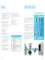
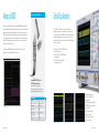
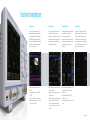
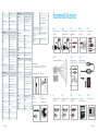
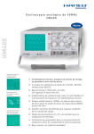
Product Brochure | 01.00 Test & Measurement R&S®HMO1002 Digital Oscilloscope 50/70/100 MHz Bandwidth Bandwidth Sampling Rate Memory Depth FFT 50 MHz, 70 MHz or 100 MHz 1 Gsample, 512 Msample per channel 1 Msample, 512 Ksample per channel The easy way to analyze the signal spectrum QuickView Key results at the push of a button Auto Measurement Versatile measurement functions and fast results At a glance High sensitivity, multifunctionality and a great price – that is what makes the R&S®HMO1002 digital oscilloscope so special. From embedded developers to service technicians to educators – with its wide range of functions, the R&S®HMO1002 addresses a broad group of users. Advanced, powerful technology in a fanless design meets the high requirements of today‘s customers. The R&S®HMO1002 digital oscilloscope includes a wide range of upgrade options, providing true investment protection for the future. Voltmeter Voltmeter measurements on both analog channel simultaneously Acquire High acquisition rate to identify signal faults Channels High vertical sensitivity down to 1 mV/div Serial Bus Analysis Function Generator MSO Pattern Generator Hardware-based triggering and decoding Common waveforms up to 50 kHz Mixed signal function as standard 4 bit wide patterns with up to 2 KBit length and 50 Mbit/s 2 R&S®HMO1002 The R&S®HMO1002 digital oscilloscope from the Rohde & Schwarz Value Instruments product range features a high waveform update rate and high vertical sensitivity, and is available with bandwidths of 50 MHz, 70 MHz and 100 MHz. The fanless instrument offers a sampling rate of 1 Gsample/s and a memory depth of 1 Msample. Like all R&S®HMO oscilloscopes, the R&S®HMO1002 includes the mixed signal function as standard. The separately available R&S®HO3508 logic probe is not coupled to a specific instrument and can be used with all R&S®HMO oscilloscopes. For communications between embedded systems and the environment, the R&S®HMO1002 includes hardware-based signal triggering and decoding for all common protocols (I2C, SPI, UART, CAN and LIN). This option can be activated with an upgrade voucher at any time. The integrated pattern generator for generating protocol messages at up to 50 Mbit/s is ideal for embedded users. In addition to using predefined messages, developers can program their own signal patterns for supported serial protocols. The integrated three-digit digital voltmeter enables service technicians to simultaneously perform voltage measurements on both analog channels with two values each. The function generator that generates different types of signals with frequencies up to 50 kHz is useful in educational settings. Trainees and students can use the R&S®HMO1002 to learn basic measurement tasks. In education mode, the convenience functions can be switched off. Thanks to 128K test points and analysis functions in the frequency domain, the R&S®HMO1002 keeps pace with significantly larger oscilloscopes. The time domain signal, measurement window, FFT analysis range and measurement result are displayed on a single screen, which makes it easier to measure the spectra. The R&S®HMO1002 offers time domain, logic, protocol and frequency analysis in a single instrument and is a member of the Rohde & Schwarz family of scope-ofthe-art oscilloscopes. R&S®HMO1002 3 Key facts Superior hardware-based acquisition for precise measurement results ❙❙ 1 Gsample/s sampling rate, 1 Msample memory depth ❙❙ High vertical sensitivity down to 1 mV/div ❙❙ Low-noise measurement due to state-of-the-art A/D converter ❙❙ High acquisition rate to identify signal faults Versatile measurement functions and fast results ❙❙ Wide selection of automatic measurement functions ❙❙ QuickView: key results at the push of a button ❙❙ Mask test: a new mask can be easily created with just a few keystrokes ❙❙ FFT: the easy way to analyze the signal spectrum 50 MHz, 70 MHz or 100 MHz Voltmeter measurements using an oscilloscope ❙❙ Three-digit display for precise voltage measurements ❙❙ Simultaneous measurement of primary and secondary voltage value per channel Future-ready investment and scalability ❙❙ Free firmware updates ❙❙ Bandwidth upgrades as required ❙❙ Serial bus analysis options via software licenses Logic analysis with the MSO option ❙❙ Mixed signal function as standard ❙❙ Precise triggering on signal events ❙❙ Straightforward display of digital signals ❙❙ Low test point loading due to active probe solution Application Serial bus analysis: hardware-based triggering and decoding ❙❙ Versatile trigger options for isolating specific data packets ❙❙ Color-coded display of decoded bus signals ❙❙ Direct export of analyzed data to USB flash drive ❙❙ Simultaneous decoding of two buses in realtime The right waveform for each application ❙❙ The right signal at hand: pattern generator up to 50 Mbit/s and function generator up to 50 kHz ❙❙ Pattern generator with standard bus signals, arb editor and counter ❙❙ Function generator with all common waveforms 4 R&S®HMO1002 Engineering lab How the R&S®HMO1002 meets your needs ❙❙ Digital pattern generator with standard bus signals and arb editor ❙❙ Automeasurement function for 28 different parameters ❙❙ Powerful zoom function ❙❙ Fanless design Analog circuit design ❙❙ Sensitivity down to 1 mV/div ❙❙ Simultaneous voltmeter measurements on both analog channels ❙❙ Component tester ❙❙ FFT with 128 kpoints Embedded ❙❙ Mixed signal function with 8 logic channels Debugging ❙❙ Hardware-accelerated triggering and decoding of serial buses ❙❙ Pass/fail tests based on user-defined masks with error signal output ❙❙ 5-digit hardware counter Education ❙❙ Function generator with all common waveforms ❙❙ Education mode 50MHz 70MHz 100MHz HV512 Depending on your requirements, the standard R&S®HMO1002 bandwidth can be upgraded from 50 MHz to 70 MHz or 100 MHz. This is done with upgrade vouchers which can be purchased at the dealer either together with the instrument or anytime thereafter. ❙❙ The upgrade voucher HV572 allows the basic 50 MHz instrument to be upgraded to a bandwidth of 70 MHz. ❙❙ Voucher HV512 increases the bandwidth from 50 MHz to 100 MHz. ❙❙ If an instrument has initially been upgraded to 70 MHz, the voucher HV712 enables you to upgrade it at any time to 100 MHz. Voucher for bandwidth upgrades or serial bus analysis options are available at the dealer. The individual voucher number and the serial number of the instrument to be upgraded is entered at http://voucher.hameg.com. The customer immediately receives the respective licence key. By loading this key via USB interface on the instrument, a 50 MHz oscilloscope is upgraded to a bandwidth of 70 MHz or 100 MHz in no time. Standard HV572 HV712 R&S®HMO1002 5 Always a MSO Optional: Logic probe R&S®HO3508 Although it is unusual for this instrument class, the standard R&S®HMO1002 model is equipped with a mixed signal functionality with no software option necessary to unlock it. Analog and digital signals can be measured and analyzed simultaneously. A real life example is the integration of ADCs (analog digital converter) or DACs (digital analog converter). In this case, the mixed signal technology allows users to determine latency periods by means of a simple cursor measurement. Therefore a MSO allows developers to devote their full attention to the circuit without having to waste energy on the measurement setup. Serial Bus Analysis I2C, SPI, CAN or LIN – in terms of interaction with the outside world for embedded systems, it is safe to say that these are the most commonly used communication protocols. The R&S®HMO1002 oscilloscopes offer you hardwareaccelerated signal triggering and decoding for all of these protocols. You can upgrade your instrument via software licence keys with those functions required to develop your application: ❙❙ HV110: Analysis of I2C, SPI and UART/RS-232 signals on analog and logic channels ❙❙ HV111: Analysis of I2C and UART/RS-232 signals on all analog channels ❙❙ HV112: Analysis of CAN and LIN signals on analog and logic channels The active logic probe R&S®HO3508 is available separately and is not linked to a specific instrument. It can be used with all R&S®HMO oscilloscopes. ❙❙ Logic probe R&S®HO3508 fits to all R&S®HMO series oscilloscopes ❙❙ No hardware lock to a specific device ❙❙ 8 logic channels available on each logic probe ❙❙ Signal threshold adjustable for each logic pod Serial bus trigger types: ❙❙ I2C: Start, Stop, ACK, nACK, Address/Data ❙❙ SPI: Start, End, Serial Pattern (32Bit) ❙❙ UART/RS-232: Startbit, Frame Start, Symbol, Pattern ❙❙ LIN: Frame Start, Wake Up, Identifier, Data, Error ❙❙ CAN: Frame Start, Frame End, Identifier, Data, Error Specifications 8 bit DAC signal change Channels 8 Memory depth per channel 512 Ksample. (HMO1002) Input impedance 100 kΩ || <4 pF Max. input frequency 350 MHz Max. input voltage 40 V (DC + peak AC) Measuring category CAT I Cable length approx. 1 m SPI bus signal, MISO / MOSI decoded 6 R&S®HMO1002 HEX decoded CAN bus signal I2C bus signal in zoom view R&S®HMO1002 7 Functions for everyday use 8 R&S®HMO1002 Pattern Generator Function Generator Digital Voltmeter (DVM) Component Tester Are you working on a distributed project, the interface definition has been completed but the prototype hardware has yet to be implemented? The R&S®HMO1002 pattern generator includes a tool for freely programmable 4-bit wide bus signals which allows you to emulate a sensor signal, for instance, to continue your work. Select the signal type suitable for your scope of application. The various basic types with frequencies of up to 50 kHz not only assist trainees and students with their measuring tasks, they also support technicians in the audio field with their assessments of filters and passes. The three-digit digital voltmeter is also a standard feature which makes the work of service technicians in particular easier. Voltage measurements can be performed simultaneously for both analog channels. Integrated into a single compact device it allows you to keep your workplace tidy. Our time proven component tester will also be at your side. Two measuring frequencies with 50 Hz or 200 Hz are provided to support your potentially tedious search for faulty components. And since a picture truly does say more than a thousand words, or rather individual values, you will be able to tell at a glance if your error analysis is on track. ❙❙ Generate protocol telegrams at speeds of up to 50 Mbit/s ❙❙ Use predefined signal patterns: I2C, SPI, UART, CAN, LIN ❙❙ Create your own patterns tailored to your needs ❙❙ Use the pattern generator as counter: a clock for your circuit with up to 25 MHz ❙❙ The function generator offers all common basic waveforms up to 50 kHz ❙❙ Available waveforms: Sine, square wave, pulse, triangle and ramp ❙❙ In tandem with the education mode which allows you to deactivate the automatic measuring functions for instruction and demonstration purposes, this will get you a powerful all-in-one instrument ❙❙ Perform measurements simultaneously on both analog channels, with two freely definable parameters each ❙❙ These options are available: DC, DCrms, ACrms, Crest Factor, Vpp, Vp+, Vp❙❙ You decide about the position of the values on the screen R&S®HMO1002 9 Frequency Analysis Due to the outstanding FFT functionality of the R&S®HMO series oscilloscopes signals can also be analysed in the frequency domain with up to 128 Kpoints. Additional practical tools such as cursor measurement as well as peak-detect-functions are also available. They allow engineers to complete their analysis significantly faster, also in the frequency domain. Figure 1: A sinusoid signal that appears undistorted at first sight Figure 2: The frequency spectrum exposes the signal distortion Figure 3: Sine burst signal in time domain Figure 4: Rectangular measurement window For non-periodic input signals most instruments offer the option to trigger the spectrum at just the right m oment to then check it in “STOP” mode at a later time. However, at that point, many oscilloscopes with FFT functionality calculate the spectrum only once and store the result in the memory. The base time signal will no longer be used for the calculation. Consequently, an investigation of all parts of the signal will no longer be possible. R&S®HMO series oscilloscopes work differently: Since FFT is also active for previously stored signals, it is possible to subsequently analyze any sections of those signals captured in single shot mode or stop mode with an adjustable window width. Figure 3 shows a sine burst signal in the time domain. Pushing the FFT button will switch the oscilloscope into the frequency domain. Users can choose between various measurement windows like the „rectangular“ type that has been used in figure 4. Although this window type captures frequencies at a high degree of accuracy, it is also accompanied by more noise. In order to suppress this disturbing interference users can for instance choose the Hanning window. The impact on the spectrum is visible in figure 5 (see device screen). Easy analysis in frequency domain Quite often the distortion of input s ignals cannot be detected with the naked eye. For instance, the sine wave signal displayed in figure 1 appears to be undistorted. Only the frequency spectrum (figure 2) - available with just one touch of a button - clearly displays additional harmonics that occur as harmonic oscillations for multiples of the basic frequency. Figure 5 10 R&S®HMO1002 R&S®HMO1002 11 R&S®HMO1002 50/70/100MHz 2-channel mixed signal oscilloscopes Firmware: ≥ 5.0 All data valid at 23°C after 30 minute warm-up. Max. input voltage: 200 Vp (derates at 20 db/decade to 5 V above 100 kHz) Noise rejection: ±5 Div (from center of screen) Trigger hold-off: Channel isolation: 35 dB from DC to specified bandwidth (same V/Div range) External trigger input (BNC) Position range: Display min. level: 1.5 Div (> 5 mV/Div) selectable with AC, DC and HF coupling Video Sync. pulse polarity: positive, negative Time base auto, 50 ns to 10 s supported standards: NTSC, SECAM, PAL, PAL-M, SDTV 576i, HDTV 720p, HDTV 1080i, HDTV 1080p Accuracy: 50.0 x 10⁻⁶ Aging: 10.0 x 10⁻⁶ per year Memory Zoom: up to 50.000 : 1 Cursor measurements: voltage (V1, V2, ∆V), time (t1, t2, ∆t, 1/∆t), ratio X, ratio Y, pulse and edge count (pos/neg), peak values (Vpp, Vp+, Vp-), mean/RMS/standard deviation, duty cycle (pos/neg), rise/fall time (80%, 90%), ratio marker, crest factor Impedance: 1 MΩ || 16 pF ±2 pF Field: even/odd, either Operation Modes Display: 16,5 cm (6,5“) VGA Color Display XY mode: CH1, CH2 Trigger level: 0.3 Vpp to 10 Vpp Line: line number selectable, all REFRESH: 2 ns/Div to 50 s/Div Resolution: 640 (H) x 480 (V) Pixel Inversion: selectively all analog channels Max. input voltage: 100 Vp Sources: all analog channels, external (AC, DC) ROLL: 50 ms/Div to 50 s/Div Quick measurements: (QUICKVIEW) Backlight: 400 cd/m2 (LED) Logic channels (with logic probe HO3508) Coupling: DC, AC Serial Busses Thresholds: TTL, CMOS, ECL, user-definied (-2 V to +8 V) Trigger output via AUX OUT (BNC) Bus representation: Analog channels: 2 x 500 MSa/s or 1 x 1 GSa/s Marker: Logic channels: 8 x 500 MSa/s Memory depth: 2 x 500 kPts or 1 x 1 MPts Frequency counter (hardware based) Resolution: 8 Bit, (HiRes up to 16Bit) Resolution: 5 digit Waveform arithmetics: refresh, roll (loose/triggered), average (up to 1024), envelope, peak detect (2 ns), filter (low-pass, adjustable), high resolution (up to 16 bit) Frequency range: 0.5 Hz to 100 MHz Accuracy: 50.0 x 10⁻⁶ Aging: ±10.0 x 10⁻⁶ per year automatic, max. sampling rate, max. waveform rate Mask Testing Functions: Pass/Fail comparison with an user-definied mask performed on waveforms Display range in horizontal direction without menu bar: 12 Div (600 Pixel) with menu bar: 10 Div (500 Pixel) Impedance: 100 kΩ || 4 pF Display range in vertical direction: 8 Div (400 Pixel) Coupling: DC with Virtual Screen usage: 20 Div Max. input voltage: 40 Vp Color depth: 256 colors Levels of trace brightness: Trace display: Functions: Pulse output for every acquisition trigger event, error output on mask violation Acquisition System Up to two busses can be analyzed at the same time. Color-coded display of decoded data in ASCII, binary, decimal and hexadecimal format. Option code realtime sampling rate voltage (Vpp, Vp+, Vp-, Vrms, Vmean), rise/fall time, frequency, period plus 6 additional measurement functions (see automatic measurement functions, freely selectable) up to 8 freely positionable markers for easy navigation Output level: 3 V Trigger system Pulse polarity: positive 32 Trigger mode Pulse width: pseudo-color, inverse brightnes Auto: Triggers automatically also without any specific trigger event >150 ns (trigger event), >0.5 µs (mask violation) Trigger types DSO Mode: CH1, CH2 Normal: Triggers only on specific trigger events Edge MSO Mode: CH1, POD (with Logic Probe HO3508) Single: Triggers once on a trigger event Direction rising, falling, both Trigger types by protocols Trigger indicator: Screen and panel (LED) Trigger coupling auto level AC, DC, HF I2C: Start, Stop, ACK, NACK, Address/Data all analog channels: sin(x)/x, linear, sample-hold Sources: all analog channels Switchable filters LF, noise rejection SPI: Start, End, Serial Pattern (32 Bit) logic channels: pulse Mask definition: Sources all analog and digital channels, AC line, external (AC, DC) UART/RS-232: Startbit, Frame Start, Symbol, Pattern Delay Mask enclosing acquired waveform with user-defined tolerance LIN: Frame Start, Wake Up, Identifier, Data, Error pre-trigger: 0 to 500.000 Sa x (1/sample rate), multiplied by 2 in interlaced mode Actions Polarity positive, negative CAN: post-trigger: 0 to 8x106 Sa x (1/sample rate) Functions equal, not equal, lower, higher, within/ without a range Frame Start, Frame End, Identifier, Data, Error Waveform update rate: up to 10,000 Wfm/s Horizontal System Waveform display: dots, vectors, persistence afterglow Pulse duration 16ns to 10s, resolution min. 2ns Display Persistence afterglow: min. 50 ms Trigger coupling Sources all analog channels Time domain (Yt): AC: <5 mV/Div: 10 Hz to 65 MHz >5 mV/Div: 10 Hz to 65/90/130 MHz Logic DC: <5 mV/Div: DC to 65 MHz >5 mV/Div: DC to 65/90/130 MHz Boolean operators: AND, OR, TRUE, FALSE time based operators: equal, not equal, lower, higher, within/ without a time range, timeout Duration: 16 ns to 10 s, resolution min. 2 ns States: H, L, X Component tester: voltage (X), current (Y) Sources: all logic channels Reference signals: up to 4 references Channel deskew: ±32 ns, step size 2 ns Vertical System Analog channels Y-bandwidth (-3dB) Trigger sensitivity (1 mV, 2 mV)/Div: 50 MHz up to 5mV/Div: 1.5 Div (5 mV to 10 V)/Div: 50 MHz (basic unit) 70 MHz (with HOO572/HV572 option) 100 MHz (with HOO512/HV512 or HOO712/HV712 option) from 5mV/Div: 0.8 Div Lower AC bandwidth: 2 Hz Bandwidth limitation (switchable): about 20 MHz Rise time (calculated, 10%-90%) 50 MHz (basic unit): <7 ns basic unit with 70 MHz option: <5 ns basic unit with 100 MHz option: <3.5 ns DC gain accuracy (all ranges): 3% of full scale with auto level: adjustable between peak values of a signal without auto level: ±5 Div (from center of screen) external ±5.0 V all analog channels: 1 mV/Div to 10 V/Div coarse stepping: 13 calibrated steps, 1-2-5 sequence variable stepping: freely between calibrated steps selectable filters Impedance: 1 MΩ II 16 pF ±2 pF Coupling: DC, AC, GND LF (low pass): 12 R&S®HMO1002 HF: HOO11: HOO12: Pulse width Trigger level setting Input sensitivity range HOO10: <5 mV/Div: 30 kHz to 65 MHz >5 mV/Div: 30 kHz to 65/90/130 MHz DC to 5 kHz (-3db), selectable in DC and auto level mode Functions: Frequency domain (FFT): Analysis of I C, SPI, UART/RS-232 signals on analog and logic channels 2 Analysis of I C, SPI, UART/RS-232 signals on all analog channels 2 Analysis of CAN and LIN signals on analog and logic channels Record modes: Interpolation main screen, time domain and zoom window time domain and frequency domain window (FFT) XY mode: voltage (XY) VirtualScreen: virtual display of ±10 Div for all math, logic, bus, reference signals on mask violations: beep, acquisition stop, screenshot, trigger pulse, automatically saving trace data during acquisiton: Statistics: number of completed tests, number of passes / failed acquisitions (absolute and in percent), test duration Waveform measurements and Operation Operation: menu-driven (multilingual), auto-set, help functions (multilingual) Waveform maths Automatic measurements: voltage (Vpp, Vp+, Vp-, Vrms, Vavg, Vmin, Vmax), amplitude, phase, frequency, period, rise/ fall time (80%, 90%), pulse width (pos/ neg), burst width, duty cycle (pos/neg), standard deviation, delay, crest factor, overshoot (pos/neg), edge/pulse count (pos/neg), trigger period, trigger frequency Functions. addition, substraction, multiplication, division Sources: CH1, CH2 Quickmath Frequency Analysis (FFT) Parameters: frequency span, center frequency, vertical scale, vertical position FFT length: 2 Kpts, 4 Kpts, 8 Kpts, 16 Kpts, 32 Kpts, 64 Kpts, 128 Kpts R&S®HMO1002 13 Scale: dBm, dBV, Vrms Waveform arithmetics: refresh, envelope, average (up to 512) Cursor measurement: 2 horizontal cursors, previous/next peak search Sources: all analog channels Pattern Generator Display (3-digit): Functions: Sources square wave / probe adjust, bus signal source, counter, programmable pattern Square wave (Probe ADJ output): frequency range: 1mHz to 500kHz level: 2.5Vpp (ta < 4ns) polarity: normal, invert duty cycle: 1% to 99% I2C (100 kBit/s, 400 kBit/s, 1 MBit/s), SPI (100 kBit/s, 250 kBit/s, 1 MBit/s), UART (9600 Bit/s, 115,2 kBit/s, 1 MBit/s), CAN (up to 50 MBits/s), LIN (up to 50 MBits/s) Counter (4 Bit): frequency: 1 mHz to 25 MHz direction: incrementing, decrementing Programmable pattern (4 Bit): sampling time: 20 ns to 42 s memory depth: 2048 sa pattern idle time: 20 ns to 42 s Waveform modes: DC, sine, square, triangle/ramp, pulse Sine: frequency range: 0.1 Hz to 50 kHz flatness: ±0.5 dB relative to 1kHz Square: frequency range: 0.1 Hz to 50 kHz rise time: <4 µs Triangle/ramp: frequency range: 0,1 Hz bis 10 kHz DC, DCrms, ACrms, Vpp, Vp+, Vp-, crest factor all analog channels +5 °C to +40 °C Storage temperature range: -20 °C to +70 °C Rel. humidity: 5% to 80% (without condensation) Mechanical Data Testing frequency: 50 Hz, 200 Hz Dimensions (W x H x D): 285 mm x 175 mm x 140 mm Voltage: 10 Vp (open) Net weight: 2.5 kg Current: 10 mA (short) Reference potential: Ground (PE) Recommended Accessories HZO50 HZO51 HZO20 HZO30 HZ115 AC/DC Current Probe 30 A, DC to 100kHz AC/DC Current Probe 100/1000 A, DC to 20kHz High voltage probe 1000:1 (400 MHz, 1000 Vrms) 1 GHz active probe (0.9 pF, 1 MΩ) Differential Probe 100:1/1000:1 HO3508 HZO40 HZO41 8 channel logic probe (350 MHZ, 4pF) Active differential probe 200 MHz (10:1, 3.5 pF, 1 MΩ) Active differential probe 800 MHz (10:1, 1 pF, 200 kΩ) HZ51 HZ52 HZ53 HZO90 HZO91 150 MHz passive probe 10:1 (12 pF, 10 MΩ) 250 MHz passive probe 10:1 (10 pF, 10 MΩ) 100 MHz passive probe 100:1 (4.5 pF, 100 MΩ) Carrying case for protection and transport 4 RU 19” rackmount kit Interfaces for mass storage (FAT16/32): 1 x USB-Host (Typ A), max. 500 mA for remote control: Ethernet (RJ45), USB Device (Typ B) General Data Application memory: 3 MB for references and device settings Save/Recall device settings: traces: on internal file system or external USB memory, available file formats: SCP, HDS on internal file system or external USB memory, available file formats: BIN (MSB/ LSB), FLT (MSB/LSB), CSV, TXT, HRT display or acquisition data sources: single or all analog channels screenshots: on external USB memory, available file formats: BMP, GIF, PNG Sampling rate: 978 kSa/s Frequency accuracy: 50.0 x 10 Realtime Clock (RTC): Aging: ±10.0 x 10⁻⁶ per year Power supply: Accessories included: Line cord, printed operating m anual, 2 probes : HZ154 (100MHz, 10:1/1:1 switchable), HZ20 adapter BNC plug /4 mm banana socket, software-CD Printed operating manual software-CD Mixed Signal Oscilloscope 50/70/100 MHz R&S®HMO1002 on external USB memory, available file formats: BIN (MSB/LSB), FLT (MSB/LSB), CSV, TXT data: frequency range: 0.1 Hz to 10 kHz duty cycle: 10% to 90% date and time Amplitude AC supply: 100 V to 240 V, 50 Hz to 60 Hz, CAT-II high impedance load: 60 mVpp to 6 Vpp Power consumption: max. 25 W 50 Ω load: 30 mVpp to 3 Vpp Accuracy: 3% DC offset: ±3 V 14 R&S®HMO1002 Operating temperature range: voltage (X), current (Y) Pulse: -6 in line with IEC 61010-1 (ed. 3), IEC 61010-2-30 (ed. 1), EN 61010-1, EN 61010-2-030 , CAN/CSA-C22.2 No. 61010-1-12 , CAN/CSA-C22.2 No. 610102-030-12 ,UL Std. No. 61010-1 (3rd Edition) , UL61010-2-030 Parameters: reference waveforms: Function Generator Safety: Primary and secondary measurement value per channel, simultaneous measuring on all channels Component Tester Functions: Bus Signal Source (4 Bit): Digital Voltmeter TestDeutsch & Measurement / Englisch Hanning, Hamming, Rectangular, Blackman Benutzerhandbuch / User Manual Benutzerhandbuch / User Manual Window: HZ154 HZ20 10/100 MHz passive probe Adapter BNC plug / 4 mm banana socket R&S®HMO1002 15 value-instruments.com HAMEG Instruments GmbH Industriestr. 6 | 63533 Mainhausen | Germany | Phone +49 (0) 6182 8000 R&S® is a registered trademark of Rohde & Schwarz GmbH & Co. KG HAMEG Instruments® is a registered trademark of HAMEG Instruments GmbH Trade names are trademarks of the owners PD 3607.0152.32 | Version 01.00 | 05 / 2014 | © HAMEG Instruments GmbH Data without tolerance limits is not binding | Subject to change 3607015232 PD 3607.0152.32 V 01.00 PDP1 en www.hameg.com