1
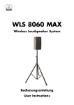
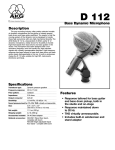
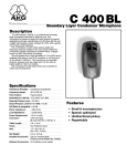
Bedienungshinweise. . . . . . . S. 2
User Instructions . . . . . . . . . p. 17
Mode d’emploi . . . . . . . . . . . p. 31
Istruzioni d’uso . . . . . . . . . . . p. 46
Modo de empleo . . . . . . . . . p. 60
Instruções de uso . . . . . . . . p. 75
Bitte vor Inbetriebnahme des Gerätes lesen!
Please read the manual before using the equipment!
Veuillez lire cette notice avant d’utiliser le système!
Prima di utilizzare l’apparecchio, leggere il manuale!
Antes de utilizar el equipo, lea por favor el manual!
Por favor leia este manual antes de usar o equipamento!
1 Precautions
Spill no liquids on the equipment and do not drop any
objects through the ventilation slots in the equipment.
1.1
Do not place the equipment near heat sources such as
radiators, heating ducts, or amplifiers, etc. and do not
expose it to direct sunlight, excessive dust, moisture,
rain, mechanical vibrations, or shock.
1.2
2 Description
Thank you for purchasing a Discreet Acoustics
module. The Discreet Acoustics Modular Series comprises five Capsule Modules and ten Installation
Modules. All modules are interchangeable so you can put
together the ideal Discreet Acoustics Modular microphone for every application at any location.
2.1. Introduction
CK 31 (Order no. 2765Z0020): Screw-on cardioid
Capsule Module.
With W 30 foam windscreen.
CK 32 (Order no. 2765Z0021): Screw-on omnidirectional Capsule Module.
With W 30 foam windscreen.
CK 33 (Order no. 2765Z0022): Screw-on hypercardioid Capsule Module.
With W 30 foam windscreen.
CK 47 (Order no. 2765Z0023): Screw-on hypercardioid Capsule Module. Acoustically equivalent to
the proven AKG C 747.
With W 70 foam windscreen.
CK 80 (Order no. 2765Z0024): Screw-on hypercardioid Capsule Module with speech-optimized frequency response.
With W 80 foam windscreen.
2.2. Capsule
Modules
The W 30 is a newly designed, two-layer windscreen. Two
different materials provide optimum rejection of wind
noise. The dark-gray outer layer swirls the impinging air
stream. The colored inside layer is more permeable to air
and acoustically neutral. It steadies the air stream before
2.3. W 30
Windscreen
17
2 Description
it hits the diaphragm. This two-stage process cuts wind
noise extremely efficiently.
2.4. Installation
Modules
18
GN 15 (Order no. 2765Z0001): 15-cm (6-in.) gooseneck with DPA external in-line XLR phantom power
adapter for permanent screw-on installation.
GN 15 E (Order no. 2765Z0002): 15-cm (6-in.) gooseneck with integrated XLR phantom power adapter for
temporary installation and PS 3 F-Lock panel mount
socket.
GN 30 OC (Order no. 2765Z0005): 30-cm (12-in.)
gooseneck with unterminated leads for permanent
screw-on installation
GN 30 (Order no. 2765Z0003): 30-cm (12-in.) gooseneck with DPA external in-line XLR phantom power
adapter for permanent screw-on installation.
GN 30 E (Order no. 2765Z0004): 30-cm (12-in.) gooseneck with integrated XLR phantom power adapter for
temporary installation and PS 3 F-Lock panel mount
socket.
GN 50 (Order no. 2765Z0008): 50-cm (20-in.) gooseneck with DPA external in-line XLR phantom power
adapter for permanent screw-on installation.
GN 50 E (Order no. 2765Z0004): 50-cm (20-in.) gooseneck with integrated XLR phantom power adapter
for temporary installation and PS 3 F-Lock panel
mount socket.
HM 1000 (Order no. 2765Z0010): Hanging module
with 10-m (33-ft.) antitwist cable and DPA in-line XLR
phantom power adapter.
LM 3 (Order no. 2765Z0015): Lavalier module
comprising:
- connection socket (with no LED ring) with 1.5-m.
(5-ft) cable with DPA in-ine XLR phantom power
adapter;
- clamp for fixing the capsule to clothing or stage
decorations;
- belt clip for the DPA phantom power adapter.
LM 3 L (Order no. 2765Z0016): Lavalier module comprising:
- connection socket (with no LED ring) with 1.5-m. (5-ft)
cable with 3-pin mini XLR connector for connecting
2 Description
the capsule to AKG bodypack transmitters PT 60,
PT 61, PT 80, or PT 81;
- clamp for fixing the capsule to clothing or stage
decorations.
B 18 battery power supply for all Installation Modules
except GN 30 OC and LM 3 L.
N 62 E, N 66 E AC power supplies for all Installation
Modules except GN 30 OC and LM 3 L.
PS3F-Lock panel mount socket for GN 15 E, GN 30 E,
and GN 50 E Installation Modules (see figs. 16 and 17).
H 500 shock mount for GN 15 E, GN 30 E, and GN 50 E
Installation Modules (see fig. 13).
H 600 + A608 shock mount for all Installation Modules
except HM 1000.
SA 40, SA 50 stand adapters for all Installation Modules except HM 1000, LM 3 and LM 3 L (see figs. 19, 20,
and 21).
SA 80 clamp for GN 15 E, GN 30 E, and GN 50 E Installation Modules (see figs. 22 and 23).
ST 1, ST 5/3, ST 45, ST 46 table stands for all Installation Modules except HM 1000, LM 3, and LM 3 L (see
figs. 18, 19, 20, and 21).
2.5. Optional
Accessories
19
3 Microphone Applications
Note that both the maximum working distance and the
area covered by the microphone depend on the pickup
angle. The smaller the pickup angle (hypercardioid), the
longer the maximum distance between the talker and the
microphone and the smaller the area covered by the
microphone.
Whether an omnidirectional, cardioid, or hypercardioid
capsule will give the best results therefore depends on
the specific application situation (see Table 1).
Note:
Omnidirectional capsules are primarily suited for recording and lavalier use.
Table 1: Microphone applications
Loudspeaker
Position
Behind the
microphone only
Application: Sound systems
Omni
Not relevant
Capsule Polar Pattern
CK 31 Cardioid
CK 32
CK 33
CK 47
CK 80
20
Working
Distance with
Gooseneck
Module
30 to 60 cm
(1 to 2 ft)
Working
Distance with
Hanging
Module
1 to 3 m
(3.5 to 10 ft.)
30 to 200 cm
(1 to 7 ft.)
1 to 7 m
(3.5 to 23 ft.)
Application: Recording only
Hypercardioid 90° to 135° off
30 to 90 cm
2 to 4 m
microphone axis
(1 to 3 ft.)
(7 to 14 ft.)
Application: Sound systems
Hypercardioid 90° to 135° off
30 to 90 cm
2 to 4 m
microphone axis
(1 to 3 ft.)
(7 to 14 ft.)
Application: High quality sound reinforcement even in acoustically difficult
locations
Hypercardioid 90° to 135° off
30 to 90 cm
2-4 m
microphone axis
(1 to 3 ft.)
(7 to 14 ft.)
Application: Speech reinforcement
4 Installation and Connections
All Discreet Acoustics Modular Capsule Modules are condenser microphones and therefore require a power supply
(phantom power). The Installation Modules have been
designed for connection to microphone inputs with 9 to
52 V phantom power. To connect Installation Modules to
inputs without phantom power, refer to Section 4.6.
1. Screw the Capsule Module onto the Installation
Module.
The screw thread is relatively fine and therefore very
smooth-running. Make sure not to tilt the capsule
when placing it on the Installation Module thread
because this would damage the thread.
2. To lock the capsule, use commercial minimum-tack
screw locking adhesive that allows you to unscrew
the capsule later if need be.
Before replacing a Capsule Module, be sure to
switch your sound system OFF in order to prevent
unwanted noise.
4.1. Capsule
Modules
1. Use the supplied PS 3 F-Lock panel mount socket to
install the Installation Module in a tabletop or an
optional SA 40 or SA 50 stand adapter to mount the
Installation Module on a floor or table stand.
Note: For even better vibrational noise rejection, you can
fix the Installation Module to the tabletop with an
optional H 500 (see fig. 13) or H 600 + A 608 shock
mount (see figs. 14 and 15).
2. Use a shielded cable to connect the Installation
Module to a microphone input with phantom power.
3. If the phantom power on your mixing console is switchable, switch the phantom power on. (Refer to the
instruction manual for your mixing console.)
The Capsule Module and the LED ring (see Section 7)
will be powered from the phantom supply.
4.2. GN 15 E,
GN 30 E, GN 50 E
Installation
Modules
1. Drill an 11-mm (7/16”) hole through the tabletop.
2. Thread the connecting cable of the Installation
Module through the opening and the supplied fixing
screw.
3. Screw the fixing screw into the Installation Module
from below to fix the Installation Module in place.
4.3. GN 15, GN 30,
GN 50, GN 30 OC
Installation
Modules
Important:
4.3.1. Tabletop
Installation
21
4 Installation and Connections
Note: For even better vibrational noise rejection, you can
fix the Installation Module to the tabletop with an optional
H 600 + A 608 shock mount (see figs. 14 and 15).
4.3.2. GN 15, GN
30, GN 50 Audio
Connection
1. Plug the cable of the DPA phantom power adapter
into the female mini XLR connector on the connecting
cable of the Installation Module.
2. Use a shielded cable to connect the DPA phantom
power adapter to a microphone input with phantom
power.
3. If the phantom power on your mixing console is switchable, switch the phantom power on. (Refer to the
instruction manual for your mixing console.)
The Capsule Module and the LED ring (see Section
4.7) will be powered from the phantom supply.
Connecting to
bodypack
transmitters:
You may also connect the GN 15, GN 30, and GN 50
installation modules to a PT 60, PT 61, PT 80, or PT 81
bodypack transmitter from AKG.
All you need to do is change the wiring of the mini XLR
connector as shown in fig. 1 below:
Shield
•
1
•
Fig. 1: Connector pinout for connecting to
bodypacks
2
•
Wire bridge
3
Red (in phase)
Pin 1: shield
Pin 2: red wire (in phase)
Pin 3: bridge to pin 2
Blue wire: unused
Black wire: unused
4.3.3. GN 30 OC
Audio Connection
22
This Installation Module has been designed for 1.5 V to
10 V a-b powering. The unterminated cable provides the
following connections:
4 Installation and Connections
Red: microphone (hot), supply voltage +
Shield: Microphone (ground), supply voltage Blue: LED +
Black: LED Connect the microphone wires to a microphone input
with a-b powering. Connect the LED ring referring to
Section 4.7.
1. Prior to installing the microphone, straighten the
cable by carefully pulling it through your fingers. Make
sure not to buckle or twist the cable.
2. Fasten a hook to the ceiling, use an existing hook, or
stretch a line across the hall.
3. Pass the cable through the hook or over the line so
that it will hang at the desired height.
4. Fix the cable in place with electrician's tape. This will
prevent the cable from twisting.
4.4. HM 1000
Hanging Module
Do not tie a knot into the cable to hang it on the
hook. This may cause the cable to twist and misalign the
microphone after a while.
Important:
Fig. 2: Aligning the
microphone.
5. Hold the cable with one hand and turn the microphone carefully into the desired position as shown in
fig. 2.
Note: If you installed the microphone as described
above, the special cable will not twist and will stay
aligned even if the temperature changes.
23
4 Installation and Connections
Steadying the
microphone:
To keep the microphone steady even in a draft,
1. Stretch a suitable length of fishing line horizontally
across the room, passing the fishing line through the
eye on the HM 1000.
2. Fix the fishing line to two opposite walls so as to
create just enough downward pull to steady the
microphone laterally.
Applications:
Fig. 3: Theater stage
miking
Fig. 4: Miking up a
choir
Audio Connection:
Refer to Section 4.3. GN 15, GN 30, GN 50 Audio
Connection.
4.5. LM 3, LM 3L
Lavalier Modules
1. Screw the capsule module onto the connection
socket of the lavalier module (see fig. 5a).
2. To relieve the microphone of the strain of the cable,
insert the cable into one of the grooves in the upper
part of the clamp (see fig. 5b).
24
4 Installation and Connections
Lapel
Selvedge
Tie
Shirt
pocket
T shirt
Fig. 5a: LM 3/LM 3L
connection socket
and clamp
Fig. 5b: Fixing the LM 3/LM 3 L
3. Snap the connection socket of the lavalier module
into the holding claws on the clamp.
The holding claws let you fix the connection socket in
a 12, 3, 6, or 9 o’clock position.
4. Clamp the microphone on the user’s clothing (see
fig. 5b) as close as possible to the user’s mouth.
Remember that gain-before-feedback will be the
higher the smaller the distance between the microphone and the mouth!
5. Make sure to aim the microphone at the user’s mouth.
Note: You may also clamp the microphone to
suitable decorations (e.g., a backdrop).
1. Insert the DPA phantom power adapter into the belt
clip and fix the phantom adapter on the belt.
2. Use a shielded cable to connect the DPA phantom
power adapter to a microphone input with phantom
power.
3. If the phantom power on your mixing console is
switchable, switch the phantom power on. (Refer to
the instruction manual for your mixing console.)
4.5.1. LM 3 Audio
Connection
25
4 Installation and Connections
4.5.2. LM 3 L Audio
Connection
Connect the cable on the LM 3 L to the audio input socket
on your bodypack transmitter. Refer to the instruction
manual of your bodypack transmitter.
4.6. Connecting to
Inputs without
Phantom Power
Note: The GN 30 OC has been designed for a-b powering (1.5 to 10 V) but can be phantom powered if you
use a suitable adapter (such as the DPA).
If your mixer has no phantom power, insert an external
phantom power supply between the DPA phantom power
adapter and mixer input. We recommend the optional B
18, N 62 E, or N 66 E power supplies from AKG. Using any
power supplies not recommended by AKG may damage
your microphone and voids the warranty.
You may also consider having a qualified technician
retrofit a phantom power supply as per DIN 45596 to
balanced or unbalanced mixer inputs. The DIN 45596
standard specifies a positive voltage of 12, 24, or 48 V on
the audio lines versus the cable shield.
4.6.1. Balanced
Inputs
Fig. 6: Input transformer with center
tap (ungrounded)
Fig. 7: Input transformer without center tap (ungrounded)
26
4 Installation and Connections
4.6.2. Unbalanced
Inputs
Fig. 8: Unbalanced
input stage
If your equipment inputs are grounded or transformerless, wire either capacitors or extra transformers into the
audio lines as shown in fig. 8 in order to prevent any current leakage into the input stage.
Table 2: Standard values for Rv and 2 x Rv
VDC
Rv
2 x Rv*
12 V ±2 V
330 Ω
680 Ω
24 V ±4 V
680 Ω
1,200 Ω
48 V ±4 V
3,300 Ω
6,800 Ω
* In order to satisfy the DIN 45596 symmetry requirement,
make sure the actual values of the two resistors 2 x Rv
do not differ by more than 0.5%!
All installation modules except for the LM 3 and LM 3 L
feature an LED ring that lights to indicate the sound
system is ready to operate.
The LED rings on these Installation Modules operate off
phantom power.
If you connected the microphone correctly, the LED ring
starts glowing at moderate intensity as soon as you switch
4.7. LED Ring
4.7.1. GN 15,
GN 15 E, GN 30,
GN 30 E, GN 50,
GN 50 E, HM 1000
Installation
Modules
27
4 Installation and Connections
the system and phantom power on. This indicates that
the system is correctly wired and ready to operate
but NOT that the microphone channel is open.
4.7.2. MIC OPEN
Indication on
GN 15, GN 30,
GN 50, GN 30 OC,
HM 1000
To obtain an open channel indication, the installation technician may connect the LED ring to an external power
source. In this mode, the LED ring will light much more
brightly to draw the required attention to the open microphone.
1. Unsolder the blue (LED +) and black (LED -) wires from
the DPA phantom power adapter or the female mini
XLR connector. (Not required for the GN 30 OC.)
2. Connect the blue and black wires to a power source
delivering one of the supply voltages listed in Table 3
below:
Table 3: Electrical values for external power source
for LED ring
Voltage
Required Resistance Max. Power
6V
390Ω
0.1 W
12 V
1000 Ω
0.25 W
24 V
2200 Ω
0.25 W
48 V
4700 Ω
0.5 W
4.7.3. Defeating the
LED Ring (not applicable to GN 30 OC,
LM 3, LM 3 L)
Remove the plug-in jumper J2 from the circuit board inside
the DPA phantom power adapter referring to fig. 9.
The LED ring is nearly invisible because its color matches
that of the case.
Fig. 9: DPA circuit
board
4.8. Bass Cut
28
The DPA phantom power adapter is equipped with a bass
cut filter to minimize low-frequency noise.
To activate the bass cut filter, plug the jumper J1 on the
circuit board into the second contact as shown in fig. 9
above.
5 Specifications
Installation Module w/
Type
Polar pattern
Frequency range
Sensitivity
CK 31
CK 32
CK 33
Pre-polarized condenser microphone
Cardioid
Omni
Hypercardioid
50-20,000 Hz 20-20,000 Hz 50-20,000 Hz
20 mV/Pa
14 mV/Pa
20 mV/Pa
-34 dBV*
-37 dBV*
-34 dBV*
Electrical impedance <600 Ω
<600 Ω
<600 Ω
Rated load impedance >2000 Ω
>2000 Ω
>2000 Ω
Power requirement
9-52 V phantom power to DIN 45596 Requires DPA adapter (integrated in GN**,
LM 3, and HM 1000 Installation Modules)
Size (dia. x length)
13 x 25 mm
13 x 25 mm
13 x 25 mm
(0.5 x 0.95 in.) (0.5 x 0.95 in.) (0.5. x 0.95 in.)
Connector**
XLR-3
XLR-3
XLR-3
Installation Module w/
Type
Polar pattern
Frequency range
Sensitivity
CK 47
CK 80
Pre-polarized condenser microphone
Hypercardioid
Hypercardioid
20-20,000 Hz
60-15,000 Hz
16.5 mV/Pa
30 mV/Pa
-35.5 dBV*
-30 dBV*
Electrical impedance <600 Ω
<600 Ω
Rated load impedance >2000 Ω
>2000 Ω
Power requirement
9-52 V phantom power to DIN 45596 Requires DPA adapter (integrated in GN**,
LM 3, and HM 1000 Installation Modules)
Size (dia. x length)
13 x 154 mm
13 x 128 mm
(0.5 x 5.85 in.)
(0.5 x 4.86 in.)
Connector**
XLR-3
XLR-3
* Re 1 V/Pa
** Except GN 30 OC and LM 3 L
This product conforms to the EN 540082-1 standard provided it is connected to
audio/power supply equipment with the CE mark.
29
5 Specifications
CK 31 Frequency
Response and
Polar Diagrams
CK 32 Frequency
Response and
Polar Diagrams
CK 33 Frequency
Response and
Polar Diagrams
CK 47 Frequency
Response and
Polar Diagrams
CK 80 Frequency
Response and
Polar Diagrams
Specifications subject to change without notice.
30
96
·
Kopfhörer
·
Drahtlosmikrofone
·
Drahtloskopfhörer
·
Kopfsprechgarnituren
·
Akustische
Komponenten
·
Cuffie
HiFi
·
Microfoni
senza
filo
·
Cuffie
senza
filo
·
Cuffie-microfono
·
Componenti
acustici
Printed in Austria on recycled paper.
Arbiter Pro Audio
Wilberforce Road, London NW9 6AX/ENGLAND
Tel: (0181) 202 1199, Fax: (0181) 202 7076
AKG Acoustics, Harman Pro GmbH
Bodenseestraße 228, D-81243 München/GERMANY
Tel: (089) 87 16-0, Fax: (089) 87 16-200
e-mail: [email protected]
AKG Acoustics GmbH
Lemböckgasse 21–25, P.O.B. 158, A-1230 Vienna/AUSTRIA
Tel: (43 1) 86 654-0*, Fax: (43 1) 86 654-516
Internet: http://www.akg-acoustics.com
11/99/9100 U 0969
Erikson Pro Audio
620 McCaffrey, St-Laurent, Quebec, H4T 1N1, CANADA
Tel: (514) 738-3000, Fax: (514) 737-5069
Internet: www.jam-ind.com/eriksonpro
Studer Japan Ltd.
2-43-7, Uehara, Shibuya-ku, Tokyo 151-0064/JAPAN
Tel: (813) 3465-2211, Fax: (813) 3465-2214
AKG ACOUSTICS, U.S.
1449 Donelson Pike, Nashville, TN 37217, U.S.A.
Tel: (615) 360-0499, Fax: (615) 360-0275
Microfones · Fones de ouvido · Microfones s/fios · Fones de ouvido s/fios · Microfones de Cabeça · Componentes Acústicos
Micrófonos · Auriculares · Micrófonos inalámbricos · Auriculares inalámbricos · Auriculares con micrófono · Componentes acústicos
Microfoni
Microphones · Casques HiFi · Microphones sans fil · Casques sans fil · Micros-casques · Composants acoustiques
Microphones · Headphones · Wireless Microphones · Wireless Headphones · Headsets · Electroacoustical Components
Mikrofone