1
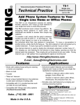
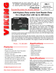
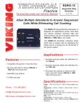
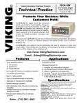
Designed, Manufactured and Supported in the USA
VIKING PRODUCT MANUAL
C O M M U N I C AT I O N & S E C U R I T Y S O L U T I O N S
SR-IP
SIP Loud Ringer/
Visual Ring Indicator
May 22, 2015
SIP Loud Ringer with Visual Ring Indication
and Remote Strobe Light Control
The SR-IP is a SIP compliant PoE powered audio device for providing loud ring and visual ring indication for
SIP VoIP phone systems. When registered with a SIP
server, the SR-IP will ring in one of 4 programmable ring
patterns and flash a bright red LED upon ring detection.
During ring detection the units internal relay contacts
will also activate providing a trigger for a Viking Model
SL-2 Strobe light or LPL-1 visual ring indicator.
Equipped with a high efficiency Class D power amplifier
and high quality loud speaker, the SR-IP is typically
over 10 times louder than a telephone speaker. The advanced features of the SR-IP include programmable
Automatic Gain Control (AGC) technology which automatically increases loud ring volume to compensate for
background ambient noise. The AGC feature is ideal for
!
variable noise environments (offices, classrooms,
restaurants, etc.), and ensures that ringing is always
heard but not unnecessarily loud.
Installation requires the assistance of a Network Administrator / IT Technician.
Features
• Programming software included
• 2 Amp relay contacts for Viking LPL-1or SL-2 strobe
light control
• Bright red visual ring indicator LED
• SIP compliant (see pg 2 for list of compatible IP-PBX
phone systems)
• PoE powered (class 2, <6.5 watts)
• Automatic Gain Control (AGC) to automatically increase ring volume to compensate for ambient noise
• Network downloadable firmware
• Surface mounts to a single gang or 4” x 4” electrical box
or directly to a wall or post
• Remotely programmable
• Extended temperature range (-40°F to 140°F)
• Remotely adjust ringer volume
• Four programmable ring cadences: normal (2 sec ON / 4
sec OFF), double, short-short-long, short-long-short
• Optional LPL-1 Remote Visual Ring Indicator (DOD#
640)
• Optional SL-2 or BLK-4-EWP strobe light kit available
(DOD# 242/653)
Applications
• Loud Ringer for noisy or variable noise enviroments
(offices, classrooms, factories)
• Visual Ring Indicator for quiet areas
(Hospitals, Church, Theater)
www.vikingelectronics.com
Information: (715) 386-8861
Specifications
Power: PoE class 2 (<6.5 watts)
Maximum Sound Pressure: 93 dB SPL @ 1m. Note: For
applications requiring louder ring, see Viking model PA-2A-IP.
Relay Output: SPDT contact, 2A @30VDC / 250VAC MAX
Dimensions: 140mm x 115mm x 38mm (5.5” x 4.5” x 1.5”)
Operating Temperature: -40° C to 60° C (-40°F to 140°F)
Humidity: 5% to 95% non-condensing
Audio Codecs: G711u, G711a, G722
Network Compliance: IEEE 802.3 af PoE, SIP 2.0
RFC3261, 100BASE-TX with auto cross over
Connections: (1) RJ45 10/100 Base-T, (3) gel-filled butt
connectors
Viking VoIP SIP System Compatibility List
NOTE: Exclusion from this list means only that compatability has not been verified, it does not mean
incompatability.
For detailed configuration instructions for certain vendors below, see Configuring Viking VoIP Phone
and SIP Servers, DOD# 944.
Infrastructure Class
Vendor
Softswitch
PBX
X
X
X
X
X
X
X
X
X
X
X
X
X
X
X
X
3COM VCX
3CX
Aastra
Asterisk
Atcom
Avaya IP Office
BlueBox
Brekeke
Cisco Unified Communications Manager (CUCM)
Cisco Unified Communications Manager Express
(CUCME)
Freeswitch
Grandstream
Interactive Intelligence
iptel.org
Kamailio
MetaSwitch
NEC
OfficeSIP
OpenSIPS
Panasonic (with SIP Extension Card)
Samsung Communications Manager (SCM)
ShoreTel
Siemens Communications Server (SCS)
SIP Express Router (SER)
sip.antisip.com
Snom PBX
Sonus
Switchvox
Teksip
Toshiba
VoIP.ms
Proxy
SBC
(session border
controller)
Service
Provider
X
X
X
X
X
X
X
X
X
X
X
X
X
X
X
X
X
X
X
X
X
X
X
2
Definitions
Client: A computer or device that makes use of a server. As an example, the client might request a particular file from the
server.
DHCP: Dynamic Host Configuration Protocol. In this procedure the network server or router takes note of a client’s MAC
address and assigns an IP address to allow the client to communicate with other devices on the network.
DNS Server: A DNS (Domain Name System) server translates domain names (ie: www.vikingelectronics.com) into an IP
address.
Ethernet: Ethernet is the most commonly used LAN technology. An ethernet Local Area Network typically uses twisted
pair wires to achieve transmission speeds up to 1Gbps.
Host: A computer or device connected to a network.
Host Name: A host name is a label assigned to a device connected to a computer network that is used to identify the device
in various forms of network communication.
Hosts File: A file stored in a computer that lists host names and their corresponding IP addresses with the purpose of mapping addresses to hosts or vice versa.
Internet: A worldwide system of computer networks running on IP protocol which can be accessed by individual computers
or networks.
IP: Internet Protocol is the set of communications conventions that govern the way computers communicate on networks
and on the Internet.
IP Address: This is the address that uniquely identifies a host on a network.
LAN: Local Area Network. A LAN is a network connecting computers and other devices within an office or building.
Lease: The amount of time a DHCP server reserves an address it has assigned. If the address isn’t used by the host for
a period of time, the lease can expire and the address can be assigned to another host.
MAC Address: MAC stands for Media Access Control. A MAC address, also called a hardware address or physical address,
is a unique address assigned to a device at the factory. It resides in the device’s memory and is used by routers to send
network traffic to the correct IP address. You can find the MAC address of your SR-IP phone printed on a white label on
the top surface of the PoE LAN port.
Router: A device that forwards data from one network to another. In order to send information to the right location, routers
look at IP Address, MAC Address and Subnet Mask.
Server: A computer or device that fulfills requests from a client. This could involve the server sending a particular file requested by the client.
Session Initiation Protocol (SIP): Is a signaling communications protocol, widely used for controlling multimedia communication sessions such as voice and video calls over Internet Protocol (IP) networks. The protocol defines the messages
that are sent between endpoints, which govern establishment, termination and other essential elements of a call.
Static IP Address: A static IP Address has been assigned manually and is permanent until it is manually removed. It is not
subject to the Lease limitations of a Dynamic IP Address assigned by the DHCP Server. The default Static IP Address is
192.168.154.1
WAN: Wide Area Network. A WAN is a network comprising a large geographical area like a state or country. The largest
WAN is the Internet.
3
Features Overview
Front View of SR-IP
Internal View of SR-IP
Microphone for
Automatic Gain
Control (AGC)
LED Ring
Indicator
Green Unit
Status LED
Reset
Switch
asdesaxtff
Yellow Network Status
LED: Lights steady to
indicate power and data
link. Blinks to indicate
network activity.
MAC:
18E80FXXXXXX
VIKING ©
PoE LAN Port 10/100, PoE Class 2 (<6.5 Watts): Connect to
your LAN via RJ45 plug and CAT5 or greater twisted pair wire.
MAC Address Label: The MAC address is a unique 12 digit number
used by routers to send network traffic to the correct IP address.
Installation
A. Wiring
Connect to Optional
Strobe Light, etc.*
Optional 2 Amp Relay
Output Contacts
Viking model
SL-2 with included
power adapter,
see DOD# 242
Rear View of SR-IP
(2A@30VDC/ 250VAC max)
120V AC
N.C. (Gray)
Not
Connected
+ _
COM. (Blue)
Green
Red
N.O. (Yellow)
3 Gel-Filled
Butt
Connectors
(included)
|
OR
|
asdesaxtff
Black
MAC:
18E80FXXXXXX
Connect to Optional Remote
Visual Ring Indicator
PCB
View of
the LPL-1
Note: The gel-filled (water-tight) butt connectors are designed for insulation displacement on 19-26 gauge wire
with a maximum insulation of 0.082 inches. Cut off
stripped wire ends before terminating.
120V AC
12VDC*
+
_
Viking model LPL-1 (DOD# 640) with Viking model
PS-2A* 12 VDC power adapter part # L120950 Go to
www.vikingelectronics.com and click on spare parts
4
B. Mounting
The SR-IP is designed to be surface mounted to a single gang box (not included), a standard 4” x 4” electrical junction
box (not included), or directly to a wall or flat sided post. Caution: For rough surfaces (ie: brick, stucco, etc.) additional
caulking may be required.
Front view of the
SR-IP
3.40"
Back Panel of the
SR-IP
Side view of the
SR-IP
1.55"
UP
3.40"
2.35"
3.30"
VIKING©
Mount back panel to a wall, a single
gang box or a 4”x4” junction box with
the arrow pointing up. Note: For
outdoor applications apply a bead of
caulk between back panel and wall.
To open the speaker box, remove the
two separate screws from the cover.
Attach the cover to the
base with the two included
screws as shown.
Typical Installation on SIP Based VoIP Phone System
Viking
SR-IP
Loud Ringer
100m (328 ft) max*
SIP VoIP PBX
or
PC with
SIP Server
Software
10/100 Mbps
Maximum
Viking
supplies
SL-2
Optional
PoE Injector
(If VoIP PBX does
not have PoE)
Optional
Switch / Hub
Customer’s
Responsibility
optional Viking
model SL-2
Strobe Light for
added visual
ring indication
Internet
(Extends range of cable, keeps
1 Gbps network speed for other
equipment on network)
* Note: A PoE extender can be used for an additional 100 meters per extender. For longer runs (up to 2 km / 1.2 miles)
a ethernet to fiber media converter can be used.
PC Requirements
• IBM compatible personal computer with:
Windows 2000 (service pack 4 or higher)
Windows XP (service pack 2 or higher)
Windows Vista (SP2 or newer), 32 or 64 bit versions
Windows 7
Windows 8
•
•
•
•
•
•
5
Adobe Acrobat Reader 8 or higher
SR-IP hardware
Available LAN with PoE (class 1, <4 watts)
Ethernet cable ( CAT5 min.)
1 MB minimum free hard drive space for installation
16MB of free physical RAM
PC Programming
A DVD is included with each SR-IP VoIP Entry phone. The DVD contains the application “Viking VoIP Phone Programming” used to program
the unit using a PC running Windows 2000, XP, Vista, Windows 7, or Windows 8 (see System Requirements above). The PC must be connected
to the same LAN as the SR-IP VoIP phone. Install the application on your PC by placing the DVD into your PC’s drive. Click “I Accept” on the
bottom of the first screen, then select “Viking VoIP Phone Programming” and click the “Install” button. Follow the directions on the screen. If
you are reinstalling the Viking VoIP Phone Programming software you must uninstall the original version first via “Add and Remove Programs”.
To start the Viking VoIP Phone Programming application, click on the Viking VoIP Phone Programming icon on your desk top. The Main screen
will appear, allowing the user to program any SR-IP phone connected to that LAN.
A. Manually Muting SIP/Network Failure Alarm Beeps (3 beeps repeated every 30 seconds)
With the unit connected and powered (Green LED on and Yellow LED off or blinking) it will output 3 beeps every 30 seconds and
turn the Red LED on and off once per second indicating a SIP registration failure, failure to receive an echo reply from pinged gateway
or Ethernet connection failure. You can manually disable the beeps by pressing and holding the RESET Switchfor 5 seconds (2
beeps will then be heard) or by clicking the “Mute Alarm Until Next Failure” tab in the Viking VoIP programming software. The LED
will continue to flash allowing you to trouble shoot the failure.
B. Configuring the SR-IP Network Settings
6
Step 1.
Open the “Viking VoIP Phone Programming” software on a windows PC that is connected to the same LAN as the SR-IP to be programmed.
Step 2.
The window in the upper left corner of the menu will show you each SR-IP that is connected to that LAN. Select the unit with the same
MAC address shown on the label located on the top of the Ethernet connector on the SR-IP.
Step 3.
Click the “Connect” button. If a pop up window appears, enter the unit’s security code (factory set to 845464) then click the “OK” button.
Step 4.
The program will then read and display the SR-IP’s IP and programming settings.
Step 5.
After adjusting the IP and phones settings, click the “Write” button under each column of settings to send the programming commands
to the connected unit.
6
C. Manually Resetting All Network Parameters to Factory Default
Step 1.
Power down the SR-IP by disconnecting the RJ45 plug.
Step 2.
Press and hold the RESET switch, then reconnect the RJ45.
Step 3.
Continue to hold the button until you hear 2 beeps, (approximately 6 seconds). Continue to hold the button until you hear 4 more
beeps, approximately 6 seconds later, then release the button. The “Ring indicator” LED will remain off for the first 3 seconds, flash
slowly for 3 seconds (2 beeps), fast flash for 6 seconds (4 beeps), then light steady indicating when to release button.
Step 4.
The unit should continue to output double beeps and slowly flash the LED indicating all Network Parameters are now reset to factory
default.
Step 5.
You must now power cycle the unit by momentarily disconnecting the RJ45.
Step 6.
You will be required to re-enter your initial network settings. See section A on page 5.
D. Speaker Mode
The Speaker Mode can be set to one of the following two modes.
OFF: In the “OFF” mode the speaker is disabled at all times. This mode is useful when using the SR-1 for visual ring indication only.
ON (factory setting): In the “ON” mode the speaker is enabled.
E. LED Mode
The LED Mode can be set to one of the following two modes.
OFF: In the “OFF” mode the LED is disabled at all times. This mode is useful when using the SR-1 for audible ring indication only.
ON (factory setting): In the “ON” mode the LED will flash while the extension is ringing.
F. Relay Mode
The 2 amp relay contacts can be programmed to one of two different modes in programming.
Loud Ring Mode: When programmed for Loud Ring Mode the relay will continuously activate while the ringing extension
is called. This mode is useful for activating a Viking model SL-2 strobe light, etc.
Loud Ring Flash Mode: When programmed for Loud Ring Flash Mode the relay will momentarily turn on and off in a
400msec on/off cadence while the ringing extension is called. This mode is useful for activating a Viking model LPL-1
remote visual ring indicator, etc.
Programming Features
A. Automatic Gain Control (AGC)
The SR-IP’s Automatic Gain Control technology automatically adjusts loud ring volume to compensate for background
ambient noise. If AGC is enabled, the ring volume will get louder or quieter by the same dB level as the ambient noise
measured just prior to the extension ringing.
For most applications using AGC, it is recommended to first set the minimum AGC ring volume to a level appropriate
for a quiet environment. AGC will then adjust the volume upward when ambient noise levels increase. To finalize settings,
make sure to test in a loud environment.
B. Loud Ring
The SR-IP can be programmed to Loud Ring or Loud Ring with AGC. Loud Ring is a fixed ring volume setting where
as Loud Ring with AGC will automatically increase or decrease the ring volume based on background ambient noise.
C. Loud Ring Cadence
The SR-IP can be programmed to ring/warble in one of 4 different distinctive ring patterns: Normal, Double, ShortShort-Long and Short-Long-Short.
7
Connection/Operation
The SR-IP connects to an on-premise SIP VoIP phone system or hosted communication server in the same way as a SIP
telephone. To register the SR-IP with the server requires the following information: 1. IP address (e.g. 192.168.1.1) of the
SIP Server 2. User Name (e.g. SIP extension number) 3. Password. When the Ringing extension is called the SR-IP will not
answer. Instead it will warble in the selected ring pattern until the ringing stops. Typically the ringing extension is programmed
as part of a hunt group so that it receives ring signal simultaneously with one or more phones to function as a loud ringer in
noisy or large areas.
Troubleshooting
If the unit cannot register with the programmed SIP server, the LED will blink on and off every two seconds, and three error
beeps will be heard every 30 seconds until communication is restored. This alerts a potential user of a problem with the device.
You may silence the error beeps, per instance, by pressing and holding the RESET Switch for 5 seconds or by clicking the
“Mute Alarm Until Next Failure” button in the Viking VoIP Programming Software (see section A on page 5). The error beeps
automatically re-enable once the unit is registered, to alert of any new problems that arise.
8
Warranty
IF YOU HAVE A PROBLEM WITH A VIKING PRODUCT, CONTACT: VIKING TECHNICAL SUPPORT AT (715) 386-8666
Our Technical Support Department is available for assistance Monday 8am - 4pm and Tuesday through Friday 8am - 5pm central time. So that we can
give you better service, before you call please:
1. Know the model number, the serial number and what software version you have (see serial label).
2. Have your Technical Practice in front of you.
3. It is best if you are on site.
RETURNING PRODUCT FOR REPAIR
The following procedure is for equipment that needs repair:
1. Customer must contact Viking's Technical Support Department at 715-386-8666 to obtain a Return Authorization (RA) number. The customer MUST
have a complete description of the problem, with all pertinent information regarding the defect, such as options set, conditions, symptoms, methods to
duplicate problem, frequency of failure, etc.
2. Packing: Return equipment in original box or in proper packing so that damage will not occur while in transit. Static sensitive equipment such as a
circuit board should be in an anti-static bag, sandwiched between foam and individually boxed. All equipment should be wrapped to avoid packing material lodging in or sticking to the equipment. Include ALL parts of the equipment. C.O.D. or freight collect shipments cannot be accepted. Ship cartons
prepaid to: Viking Electronics, 1531 Industrial Street, Hudson, WI 54016
3. Return shipping address: Be sure to include your return shipping address inside the box. We cannot ship to a PO Box.
4. RA number on carton: In large printing, write the R.A. number on the outside of each carton being returned.
RETURNING PRODUCT FOR EXCHANGE
The following procedure is for equipment that has failed out-of-box (within 10 days of purchase):
1. Customer must contact Viking’s Technical Support at 715-386-8666 to determine possible causes for the problem. The customer MUST be able to
step through recommended tests for diagnosis.
2. If the Technical Support Product Specialist determines that the equipment is defective based on the customer's input and troubleshooting, a Return
Authorization (R.A.) number will be issued. This number is valid for fourteen (14) calendar days from the date of issue.
3. After obtaining the R.A. number, return the approved equipment to your distributor, referencing the R.A. number. Your distributor will then replace the
Viking product using the same R.A. number.
4. The distributor will NOT exchange this product without first obtaining the R.A. number from you. If you haven't followed the steps listed in
1, 2 and 3, be aware that you will have to pay a restocking charge.
TWO YEAR LIMITED WARRANTY
Viking warrants its products to be free from defects in the workmanship or materials, under normal use and service, for a period of two years from the date of purchase
from any authorized Viking distributor. If at any time during the warranty period, the product is deemed defective or malfunctions, return the product to Viking Electronics, Inc.,
1531 Industrial Street, Hudson, WI., 54016. Customer must contact Viking's Technical Support Department at 715-386-8666 to obtain a Return Authorization (R.A.) number.
This warranty does not cover any damage to the product due to lightning, over voltage, under voltage, accident, misuse, abuse, negligence or any damage caused by use
of the product by the purchaser or others. This warranty does not cover non-EWP products that have been exposed to wet or corrosive environments. This warranty does not
cover stainless steel surfaces that have not been properly maintained.
NO OTHER WARRANTIES. VIKING MAKES NO WARRANTIES RELATING TO ITS PRODUCTS OTHER THAN AS DESCRIBED ABOVE AND DISCLAIMS ANY EXPRESS
OR IMPLIED WARRANTIES OR MERCHANTABILITY OR FITNESS FOR ANY PARTICULAR PURPOSE.
EXCLUSION OF CONSEQUENTIAL DAMAGES. VIKING SHALL NOT, UNDER ANY CIRCUMSTANCES, BE LIABLE TO PURCHASER, OR ANY OTHER PARTY, FOR
CONSEQUENTIAL, INCIDENTAL, SPECIAL OR EXEMPLARY DAMAGES ARISING OUT OF OR RELATED TO THE SALE OR USE OF THE PRODUCT SOLD HEREUNDER.
EXCLUSIVE REMEDY AND LIMITATION OF LIABILITY. WHETHER IN AN ACTION BASED ON CONTRACT, TORT (INCLUDING NEGLIGENCE OR STRICT LIABILITY)
OR ANY OTHER LEGAL THEORY, ANY LIABILITY OF VIKING SHALL BE LIMITED TO REPAIR OR REPLACEMENT OF THE PRODUCT, OR AT VIKING'S OPTION, REFUND OF THE PURCHASE PRICE AS THE EXCLUSIVE REMEDY AND ANY LIABILITY OF VIKING SHALL BE SO LIMITED.
IT IS EXPRESSLY UNDERSTOOD AND AGREED THAT EACH AND EVERY PROVISION OF THIS AGREEMENT WHICH PROVIDES FOR DISCLAIMER OF WARRANTIES, EXCLUSION OF CONSEQUENTIAL DAMAGES, AND EXCLUSIVE REMEDY AND LIMITATION OF LIABILITY, ARE SEVERABLE FROM ANY OTHER PROVISION
AND EACH PROVISION IS A SEPARABLE AND INDEPENDENT ELEMENT OF RISK ALLOCATION AND IS INTENDED TO BE ENFORCED AS SUCH.
If trouble is experienced with the SR-IP phone, for repair or warranty information, please contact:
Viking Electronics, Inc., 1531 Industrial Street, Hudson, WI 54016 (715) 386-8666
WHEN PROGRAMMING EMERGENCY NUMBERS AND (OR) MAKING TEST CALLS TO EMERGENCY NUMBERS:
Remain on the line and briefly explain to the dispatcher the reason for the call. Perform such tests in off-peak hours, such as early morning or late evenings.
PART 15 LIMITATIONS
This equipment has been tested and found to comply with the limits for a Class A digital device, pursuant to Part 15 of the FCC Rules. These limits are designed to provide reasonable protection against harmful interference when the equipment is operated in a commercial environment. This equipment generates, uses, and can radiate radio frequency energy and, if not installed and used in accordance with the instruction manual, may cause harmful
interference to radio communications. Operation of this equipment in a residential area is likely to cause harmful interference in which case the user will
be required to correct the interference at his own expense.
Product Support: (715) 386-8666
Due to the dynamic nature of the product design, the information contained in this document is subject to change without notice. Viking Electronics, and its affiliates and/or subsidiaries
assume no responsibility for errors and omissions contained in this information. Revisions of this document or new editions of it may be issued to incorporate such changes.
DOD# 577
Printed in the U.S.A.
9
ZF303720
Rev 1