1
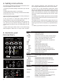
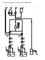
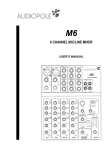
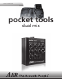
user manual pocket tools dual mix 1 pocket tools dual mix user manual ContentsPage 2 1. Introduction 3 2. Safety Instructions 4 3. Controls and Connections 4 4. Operation Summary 5 4.1 Cabling and Starting-up 5 4.2 Level Adjustment 5 5. Functional Characteristics 5 5 5.1 Inputs Channel 1 and Channel 2 5.1.1 Signal sources and preamp selection 5 5.1.2 Dual-band Equalization 6 5.2 efx – Effects Section Muliteffect 6 5.3 aux in 6 5.4 master 6 5.5 DI-out 6 5.6 24V-Phantom-Power 6 6. Technical Specifications: pocket tools dual mix 7 7. Circuit Diagram: pocket tools dual mix 8 1. Introduction Welcome to AER! Thank you for purchasing an AER Pocket Tool. You are now the owner of a professional audio preamp, designed and manufactured to the highest pro audio technical specifications; capable of shaping, maximizing and delivering the tonal character of your instrument. At AER our complete focus, some say obsession, is on the ‘true’ reproduction of natural acoustic sound. A lifetime spent listening to and working with acoustic instruments helps us to create and refine the very best devices available; to enable you to craft your own unique acoustic identity. Make your instrument the very best it can be ... Please take a moment to read this brief manual. We want you to understand how our product works and what it can do for you. We want you to gain benefit from its many features but most of all we want you to ENJOY it! The dual mix is a high-quality „two-channel“ preamplifier for instrument/line or microphone signals. The unit offers simple, efficient features just like a small mixong console: – two inputs, each for one microphone or instrument and line-level signal with switchable 24V-phantom-power – separate active two-band EQ networks for each input – a 4-preset multi-effects-unit with two reverbs, one echo and one chorus – a stereo aux-in – line-out and DI-out – plus a stereo-headphone-preamplifier This makes the dual mix especially suited for the following applications: - as channel extension in connection with AER-amplifiers (the line output of the dual mix is connected e.g. with an amp‘s effects return) - as instrument/microphone stage preamp (the line out or DI-out of the dual mix is connected directly to the mixing-desk/stagebox) - as headphone rehearsal amplifier in connection with a stereo headphone set All pocket tools need energy for their high-grade circuits and are powered by 24V-power-supplies. An appropriate supply is included in delivery. Read on and have fun using your dual mix! 3 2. Safety Instructions The following guidelines shall help minimize the risk of injury through fire or electric shock. mers, revolving machines, neon illumination etc. Do not lay signal cables parallel to power current cables. 1. Carefully read these safety notes before you use the device! 8. There are no user-serviceable components inside the unit. To avoid the risk of an electric shock, the unit must not be opened. All maintenance, adjustment and repair works should be carried out by qualified staff only. Any unauthorized tampering will void the 2-year warranty. 2. Keep these safety notes in a safe place. 3. Pay attention to all warnings, instructions and additional texts on the unit. 4. Do not install or use your device in close proximity to water or if you are wet yourself. 5. Use your device in a safe place where nobody can step on cables or trip over and damage them. 6. Always pull the mains plug before cleaning your device. Use only a dry cloth for cleaning. Avoid the use of detergents and do not let any liquids seep into the unit. 9. In keeping with the EMV regulations screened cables with correctly fitted connectors must be used for all signal connections. 10. Always use an earthed power supply with the correct mains voltage. If you are in doubt about the power outlets ground, have it checked by a qualified technician. 11. Cable up your device only when it is powered off. 7. Never install your device close to units with strong electromagnetic fields such as large mains transfor- 3. Controls and Connections pocket tools channel 1 channel 2 clip gain line/mic dual mix efx aux in level level pan master clip gain high high low low 24V phantom power line/mic select line out DI out ch.2 ch.1 dc 24 V foot switch channel 1 level head phones channel 2 1 = gnd 2 = pos 3 = neg aux in power 4 Top side gain input level control clip overload indicator line/mic signal source selector switch (combo socket): line (only via 6.3 mm jackplug) for instruments (pickup) and other line level sources mic (only via XLR-connector) for microphones high treble control low bass control efx 4-preset multi-effects unit level level control internal effect pan effect signal distribution control select effect select button with led-indicators aux in stereo-input for additional signal sources level stereo input level control master master level control Rear side dc 24 V power supply connector socket (24 Volt DC) 24V phantom power ch. 1 24V phantom power switch channel 1 ch. 2 24V phantom power switch channel 2 line out signal output, 6.3 mm mono jack socket headphones stereo-headphones socket DI out signal output, symmetrical, XLR-socket DI level DI out signal level control Front side channel 1 signal input – combo socket for 6.3 mm mono jackplug and XLR connector channel 2 signal input – combo socket for 6.3 mm mono jackplug and XLR connector aux-in stereo input for additional signal sources (e.g. CD-player), RCA-sockets (white = left channel, red = right channel), parallel: 3.5 mm stereo jack socket power on/off-status indicator 4. Operation Summary 4.2 Level adjustment 4.1 Cabling and Starting-up Note: Level adjustment Before connecting to the mains, please ensure that your local mains voltage (e.g. 230V in mainland Europe, 120V in the USA) is suitable for the voltage input range of the included power supply. The relevant specs and safety symbols are printed on the rear side of the unit. By setting the level correctly we mean that the signal level in one or several devices in a signal chain is neither too high nor too low. This applies equally to all components of a unit (here e.g. high and low). Note: 24V power supply The included 24VDC power supply is a certified widerange model, capable of handling input voltages between 100V and 240V. A substantial amount of research, effort and testing went into the selection of this power supply. It is critical to the function of the preamp – please use no other power supply! Also please bear in mind that any device powered from a power supply (as opposed to battery operation), may suffer interference carried by the electricity supply itself. To avoid this, always try and keep signal cables as short as possible. We have opted for a “non-earthed power supply“ (class 2 with protective insulation) in order to avoid unwanted earth or ground loops that occur when using several earthed mains powered devices in a signal chain. Please ensure that gain-, level- and volume-controls are turned all the way to the left and all other controls are in their middle position (centre detent). The pushbuttons should be off, i.e. not pushed. Now select the appropriate preamp function (line/mic) and make all required cable connections: 1) Instruments (1/4“ jack or XLR) or Microphones (only XLR) to input channel 1 and/or channel 2 of the dual mix 2) line-out of the dual mix e.g. to effects return of the effect loop of an AER amplifier or to the input of a downstream device You may also want to connect: 1) the DI-out of the dual mix to a mixing-desk input or a stagebox (use balanced cables for this) 2) a CD/MP3 player to aux-in or 3) a stereo headphone set to the headphones output Consequently, care must be taken that no part of the circuit is overloaded, or that distortion is unintentionally added to the signal. We have carefully designed the circuit to achieve this objective whilst also providing potentiometers (gain, level, volume) for „manual” intervention. The dual mix is equipped with two high-quality preamps which can handle line and microphone signals and have therefore a wide input sensitivity range. Having selected the appropriate preamp function (mic or line) and with the gain controls set fully counter clockwise (minimum gain), turn up the gain whilst playing your instrument until the red clip indicator LED lights up occasionally with heavy strumming. Now turn down the gain control (or the volume control on the source) by a tiny amount to allow additional headroom for undistorted reproduction. During play, the clip control LED should only flicker intermittently at most. With line (signal sources with a sufficient input signal level) the gain controls will probably sit between minimum gain and the 10 o’clock position. It’s likely that in the mic position the setting will be significantly higher. Please keep in mind that the filter stages are partly active and thus have an influence on the overall adjustment of the dual mix. 5. Functional Characteristics 5.1 Inputs Channel 1 and Channel 2 5.1.1 Signal Sources and Preamp Selection Various signal sources may be connected to the XLR/ line combo sockets (channel 1 und 2). To Line (6.3 mm jack socket): all types of active and passive pickups for acoustic instruments, electromagnetic pickups, keyboards, samplers. To XLR socket: all dynamic and condenser (vocal or instrument) microphones. The corresponding preamp is selected by the line/mic-switch. 5 5.1.2 Dual-band Equalization The dual-band equalizer of your dual mix provides you with an active and high quality sound interaction tool that supports the natural tone of instruments and voice whilst simultaneously offering you the possibility of a controlled interaction. With all controls in mid position the filters are set to produce a very pleasing and natural sound impression. The high-(treble) and low-(bass)controls allow you to modulate the sound as desired. 5.2 efx – Effects Section Multieffect The dual mix has an onboard digital effects unit with four presets: 1 = short reverb, 2 = long reverb, 3 = delay 320 ms and 4 = deep chorus, which are called up with the select effects selector switch. Each pressing of this switch will shift the preset selection by one setting. With the pan control the effect is assigned to the channels. In its centre position both channels will receive the same amount of wet signal, turned fully counterclockwise only channel 1, turned fully clockwise only channel 2 will get a wet signal. The level control adjusts the effects loudness in the master signal. 5.3 aux-in The aux-in is a stereo signal input (RCA/3.5 mm stereo jack, frontside) e.g. for a CD- oder MP3-player or a drum computer. Using the level control, the signal which is present here is blended with the master signal. Supplement to article 5.6 Information about the use of 48V or 24V phantom power (phantom power = remote supply, here: powering an audio device via the connected audio line) Turn on the phantom power only if the unit connected to the XLR socket is designed to handle it! In general, suitable units are e.g. condenser microphones, active DI boxes and other special audio devices, whose power supply is drawn from the phantom power. Such devices are also labelled accordingly; please heed the permissible power consumption (max.10mA). High-quality dynamic microphones with a balanced signal need no phantom power, but can handle it anyway. Other devices which have not been designed explicitly for phantom power operation can suffer from considerable malfunctions, and damage may result as well. Examples of devices that may be damaged by incorrect application of phantom power include: Low-cost dynamic microphones with a mono jack plug (unbalanced signal) that were fitted afterwards with an XLR connector. Audio devices with a balanced XLR output (e.g. DI boxes, effects devices, instrument preamps with a DI output etc.) which are not protected against phantom power applied to their XLR output. (The DI connectors on AER products are protected against applied phantom power.) Other audio devices (such as preamps, effects pedals etc.) whose unbalanced line output was replaced by an XLR socket. If in doubt please consult the manufacturer of the device you are using. 5.4 master The volume control adjusts the loudness of line-out and headphones together. Experiment and enjoy your new route to alternate soundscapes! 5.5 DI-out Any questions or suggestions? Please do contact us at: [email protected] The DI-out yields a balanced output signal whose level can be adjusted by the level-control. 5.6 24V Phantom power The 24V phantom power switches are located on the rear side of the housing. These provide phantom power to the XLR inputs for devices that require it, e.g. condenser mics. The 24V phantom power supply of your AER device complies with the DIN EN 61398 regulations in view of a 24V phantom power supply. Please note the adjacent text. 6 Thanks for reading! dataData: pocket tools dual mix 6.Technical Technical Inputs channels 1 and 2 aux in Switchable microphone or line input Combo socket, XLR and ¼“ jack (6.35 mm) line mode (jack input) Unbalanced high impedance input for instrument pick-ups and line-level sources Gain adjustment range: +3…+20 dB Min. input voltage: 100 mV (–20 dBV) Max. input voltage: 3 V (+10 dBV) Input impedance: 2.2 M || 60 pF Signal-to-noise ratio, A-weighted Min. gain: 108 dB Max. gain: 98 dB Frequency response: 20 Hz…20 kHz / 1 dB THD + N (1 kHz): < 0.3% mic mode (XLR input) Balanced microphone input 1 = ground, 2 = positive (+), 3 = negative (–) Gain adjustment range: +4…+40 dB Min. input voltage: 10 mV (–40 dBV) Max. input voltage: 3 V (+10 dBV) Input impedance: 2.1 k Unbalanced:1.1 k Signal-to-noise ratio, A-weighted Min. gain: 108 dB Max. gain: 93 dB Frequency response: 20 Hz…20 kHz / 1 dB THD + N (1 kHz): < 0.1% Phantom power: 24 V, R = 1.2 k per terminal, switchable for each channel, total current max. 10 mA per channel, short circuit protected Warning: External equipment may be damaged by inappropriate use of phantom power. In case of doubt keep the 24 V phantom power switch off (not pushed). Clip indicator Red LED Headroom: 8 dB Auxiliary stereo input (mono-mixed), e.g. for CD player Cinch (RCA) sockets (left / right) and 3.5 mm stereo jack socket. Level control Min. input voltage: 2 x 250 mV (–14 dBV) Max. input voltage: 2 x 10 V (+20 dBV) Input impedance: 10 k Outputs line out headphones Unbalanced line output after master Mono jack, ¼” (6.35 mm) Nominal output voltage: 1 V (0 dBV) Max. output voltage: 9 V (+19 dBV) Output impedance: 47 Min. load impedance: 2 k Residual noise (master fully anticlockwise): A-weighted: 1 μV (–120 dBV) Headphones output Stereo jack, ¼” (6.35 mm) Output power, 1 kHz, THD = 1%: Typ. 2 x 40 mW / 32 Residual noise (master fully anticlockwise): A-weighted: 3.3 μV (–110 dBV) Warning: Suitable for headphones with stereo jack only. Do not connect any mono jacks. DI-out Balanced XLR output 1 = ground, 2 = positive (+), 3 = negative (–) Level control Nominal output voltage (differential), adjustment range: 41…410 mV (–28…–8 dBV) Output impedance: 47 each terminal to ground Min. load impedance (differential): 1 k Residual noise (both channels in line mode), A-weighted: 3.3 μV (–110 dBV) Tone controls channels 1 and 2 low high 12 dB at 100 Hz (shelf type) 13 dB at 10 kHz (shelf type) Effects Built-in effect Digital effect processor with 4 presets 1 = Reverb with short predelay 2 = Reverb with long predelay 3 = Repeating delay 4 = Chorus Footswitch connector footswitch Connector for a dual footswitch Stereo jack, ¼” (6.35 mm) Tip = footswitch for muting channel 1 Ring = footswitch for muting channel 2 Sleeve = ground (common) Function: Switch ON = channel muted Power Supply voltage Mains adapter 24 V=, 0.5 A Use only supplied mains adapter. Mains voltage: 100-240 V~ Power consumption when used with Dual Mix: max. 10 W General Metal housing Aluminium Finish Dimensions Anodized black 65 mm (2.56“) high 105 mm (4.13“) wide 135 mm (5.31“) deep 480 g (1.06 lbs) Weight Definitions and conditions Input and output voltages are RMS values for a sine signal and 1 kHz unless stated otherwise. Tone controls in neutral position unless stated otherwise. Min. input voltage: Input voltage for nominal output voltage at line out with gain and master fully clockwise. Max. input voltage: Permissible input voltage that does not cause distortion more than the rated THD + N (assuming suitable control settings). Signal-to-noise ratio (SNR): Ratio of nominal output voltage to noise voltage at line out, at specified gain setting, master fully clockwise, input shorted, 20 Hz…20 kHz. Note: The SNR found at line out may be less than the SNRs specified for the channels because both channels contribute to the output noise. Residual noise: Noise voltage at an output when all gain and level settings are minimal. THD + N: Total harmonic distortion + noise for nominal output voltage at line out Specifications and appearance subject to change without notice. TD20111123 7 Aux In LINE CHANNEL 2 1 MIC 3 CHANNEL 2 LINE 1 MIC 3 CHANNEL 1 2 2 R T GAIN LINE/MIC +24 V High impedance GAIN LINE/MIC +24 V 24 V PHANTOM POWER CH. 2 High impedance 1.2 k 1.2 k 8 1.2 k 1.2 k 24 V PHANTOM POWER CH. 1 LOW LOW HIGH HIGH Clip Clip MUTE PAN MUTE SELECT Digital EFX 1 2 3 4 AUX IN LEVEL DI LEVEL MASTER R R 3 1 2 DI OUT LINE OUT HEADPHONES FOOTSWITCH B090529B_20111111 T T 7. Circuit Diagram: pocket tools dual mix notes 9 notes 10 notes 11 www.aer-amps.com DualMix - 2011_11_GB