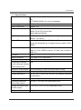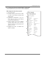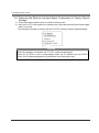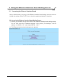
1
Ethernet Interface Board MODEL : IF1-ET01 User’s Manual Ver.2.10 CITIZEN SYSTEMS JAPAN CO., LTD. 6-1-12, Tanashi-cho, Nishi-Tokyo-shi, Tokyo, 188-8511, Japan TEL: +81-424-68-4608 [email protected] http://www.citizen-systems.co.jp/english/ Contents Contents ......................................................................................................................... 2 Read before using ......................................................................................................... 3 Safety Instructions ........................................................................................................ 4 1. Introduction ............................................................................................................. 6 1-1. Specifications ......................................................................................................................... 7 1-2. Part Names and Functions ................................................................................................... 8 2. Preparing the IF1-ET01 ........................................................................................... 9 2-1. Using the Panel Button ........................................................................................................ 9 2-2. LED Functions..................................................................................................................... 10 2-3. Printing the Ethernet Interface Board Configuration ..................................................... 11 2-4. Returning the Ethernet Interface Board Configuration to Factory Default Settings.... 12 3. Using the Ethernet Interface Board Setting Screen ........................................... 13 3-1. Connecting the Ethernet Interface Board ......................................................................... 13 3-2. Checking or Changing Ethernet Interface Board Configuration .................................... 14 3-3. Checking the Operational Status of Printer ..................................................................... 17 3-4. Checking the Ethernet Interface Board Version Information ......................................... 18 4. Setting the IP Address .......................................................................................... 19 5. Network Seeker ..................................................................................................... 20 5-1. Starting Network Seeker .................................................................................................... 20 5-2. Changing Settings ............................................................................................................... 22 6. Installing the Ethernet Interface Board Unit and Connecting to the Network .. 22 2 Read before using Be sure to read this manual carefully before using the product. After you read it, store it in a safe place so that you can reread it when necessary. Contents of this manual may be changed without notice. Reproducing and/or copying the contents of this manual by any means without permission are prohibited. We will not be responsible for any adverse occurrence that results from the use of this manual, regardless if it contains omissions, errors/misprints, etc. Note that we will not be responsible for (a) loss caused by improper operation or mishandling of the device by the user, or (b) loss due to operational environment. Data etc., are basically impermanent; long time or permanent storing/saving of data by the device is not possible. Note that we will not be responsible for any loss or loss of profits owing to loss of data due to breakdown, repairs, inspections, etc. Please contact us if there are omissions, errors, ambiguities, etc. in this manual. Refer to this document along with the user manual of the printer. This product operates by setting up a wireless connection between itself and other wireless LAN equipment for data transmission. Therefore, other wireless LAN equipment is required to use this product. While we have confirmed the operation of this product with certain wireless LAN equipment, operation with all types of wireless LAN equipment is not guaranteed. Carry out a sufficient evaluation before using this product. Trademarks ・ Microsoft, Windows XP, Windows Vista, Windows 7 and Windows 8 are registered trademarks of Microsoft Corporation U.S.A. ・ Other company names and product names mentioned here are trademarks or registered trademarks of those companies. 3 Safety Instructions Before handling the product (removing from packaging, etc.), discharge static electricity by touching metal, etc. Do not spill liquid onto the device. Do not place the device in a humid place. Do not step on, or subject the network cable connected to the device to rough treatment. Do not connect a telephone line to the RJ45 connector on the device. Be sure to connect STP cable (category 5 or higher). Connect the product only to devices that operate on SELV voltage (safety extra-low voltage). Be sure to use the device inserted in the interface board slot of the printer. Do not use the device when it is not inserted in the interface board slot. 4 Safety Instructions Important FCC Radiation Exposure Statement The radiation exposure from this equipment is within the FCC RF radiation exposure limits for an uncontrolled environment. It is recommended that you install and operate this equipment with a minimum of 20 cm between the radiator and your body. CE Mark Warning This equipment is classified as a Class B product and may cause radio interference in a home environment. In such cases, the user is requested to take the necessary countermeasures to resolve the interference. Restrictions by Country Frequency range: 2400.0 to 2483.5 MHz Country Bulgaria Restrictions None France Outdoor use is limited to 10 mW e.i.r.p. within the band 2,454 to 2,483.5 MHz Italy None Luxembourg None Norway Implemented Russian Federation None Note: Do not use this equipment outdoors in France. 5 Notes Outdoor use and public service require general authorization. Used for military radiolocation. The 2.4 GHz band is being reformed to relax the current regulations. Full implementation is planned by 2012. Outdoor use requires general authorization. Network and service supply (not for spectrum) require general authorization. The geographical area within a radius of 20 km from the center of Ny-Ålesund is excluded from this subsection. For indoor use only. 1. Introduction Thank you for purchasing the Citizen IF1-ET01 Ethernet interface board. The IF1-ET01 Ethernet Interface Board is compatible with, for example, the Line Thermal Printer CT-S801 series and the CT-S601 series. Connecting the IF1-ET01 to a printer enables you to relay data between a network of multiple computers and the printer. In addition, the computers and printer are able to communicate with each other: the operational status, print settings, and other information about the printer can be checked from computers on the network. 6 1. Introduction 1-1. Specifications Compatible printers CT-S801 Series, CT-S601 Series, CL-S400DT, CL-S6621, etc. (CT-S2000/310/300, etc. are not compatible) Power supply DC 5 V ± 5% Power consumption Approx. 1 W Hardware CPU: NXP LPC2458 ROM: 512 kb CPU internal flash RAM: 8Mbytes SDRAM Operation panel LED: 4 (2 on panel, 2 on RJ45 connector) Button: 1 (on panel) Network I/F Auto-Negotiation (100Base-TX/10-Base-T) Automatic distinguishing of straight/crossover cables (AUTOMDIX) Connection to the printer Printer Class USB 2.0 FULL SPEED (however, CT-S801 side currently is USB 1.1) IP Version IPv4 Network protocols TCP, UDP, HTTP, ICMP, DHCP Port number for printing TCP 9100 (initial value) Configuration changes Yes from the Ethernet interface board setting screen Interactive communication Yes (only when CITIZEN TCP/IP port driver is used) Firmware upgrade Yes (using the Ethernet interface board setting screen) External dimensions 80 mm (W) x 70 mm (D) x 25 mm (H) (including connector protuberance) Weight Approx. 75 g Operating temperature 0 to 40°C, 10 to 90% RH (condensation free) and humidity ranges Storage temperature and -20 to 90°C, 10 to 91% RH (condensation free) humidity ranges Safety standards VCCI Class A 7 1. Introduction 1-2. Part Names and Functions Ethernet interface board unit Printer interface connector ① ② Operation panel ⑤ ③ ④ ① RJ45 connector (compatible with 10Base-T/100Base-TX) Connection for LAN cable. ② Network transmission speed indicator*1 Shows network transmission speed with steady/blinking light. (Green) ③ Network status indicator*1 Shows network connection status (disconnected, receiving data, etc.). (Yellow) ④ Board status indicator*1 Shows operational status of the IF1-ET01 with combinations of steady and blinking lights. (Red/green) ⑤ Panel button*2 Used to operate the IF1-ET01. *1 For indicator details, see “2-3. LED Functions” (page 10). *2 For panel button operations, see “2-2. Using the Panel Button” (page 9). 8 2. Preparing the IF1-ET01 2-1. Using the Panel Button The panel button on the operation panel is used to operate the IF1-ET01. You can use it to print settings information and restore factory default settings. Panel button ■ Starting the Ethernet Interface Board Switch on the printer. The IF1-ET01 starts along with the printer. ■ Printing the Ethernet Interface Board Configuration Press the panel button. For details, see “2-4. Printing the Ethernet Interface Board Configuration” (page 11). ■ Switching to Setting Mode Press and hold the panel button. The buzzer* sounds once, signaling a switch to setting mode. ・ Setting mode enables the reading of the factory default settings and printing of the firmware information. ・ If there is no activity for 3 seconds in the setting mode, the buzzer* sounds once, signaling a return to normal mode. * Note that the buzzer will not sound if the printer’s buzzer is disabled. ■ Restoring to the Factory Default Settings Switch to setting mode, then press and hold the panel button. The IF1-ET01 returns to the factory default settings. Warning When the operation is complete, the IF1-ET01 restarts automatically. When the IF1-ET01 is set to automatically obtain the IP address from the DHCP server, the IP address assigned may be different from the previous one. 9 2. Preparing the IF1-ET01 2-2. LED Functions The following charts show what each LED indicator indicates. ① ② ③ ① Network transmission speed Transmission speed LED (green) 100 Mbps On 10 Mbps / disconnected Off ② Link status with network Link status LED (yellow) Connected On Disconnected Off Transmitting data Flashing ③ Ethernet interface board status Display content LED (green) Printer: disconnected Printer: connected Network: disconnected Seeking IP address Network: connected Resource error System error LED (red) Off - On - Off - Flashing (0.5 second cycle) On - Alternating blinking (0.5 second cycle) Alternating blinking (0.1 second cycle) 10 Description Not connected to printer Connected to printer Not connected to network Seeking IP address from DHCP server Network setting is complete The IF1-ET01 is malfunctioning The IF1-ET01 is malfunctioning 2. Preparing the IF1-ET01 2-3. Printing the Ethernet Interface Board Configuration Press the panel button to print out the IF1-ET01 configuration. ■ Configuration items that are printed ① Title of the printout. ② Firmware version of the IF1-ET01. Same ① as noted on the Ethernet interface board setting screen. PrintServer: DQ00-05XX ② ③ Configuration programmed in the IF1interface board setting screen. ③ currently being used by the IF1-ET01. When the network is not connected, the IP address is “0.0.0.0”. ④ ⑤ 11 MAC Address :00:01:02:0a:0b:0c Ethernet :Auto-detect DHCP :Enable IP Address(Fixed) :192.168.10.101 Subnet Mask :255.255.255.0 PrintPort :9100 Receive Timeout :180 Manufacturer :CITIZEN SYSTEMS CO.,Ltd. Model :IF1-ET01 Serial Number :10100016 Host Name :no name Network ⑤ Displayed only when “IP address from DHCP” is “Enable”. Mar 28 2014/11:56:22 Configuration ET01. Same as noted on the Ethernet ④ Network settings such as the IP address I/F Board Information Ethernet :Auto-detect IP Address :192.168.128.212 Subnet Mask :255.255.254.0 100BaseTx/Full Broadcast :192.168.129.255 MTU :1500 DHCP Server :192.168.128.1 Gateway :192.168.128.1 DNS1 :0.0.0.0 DNS2 :0.0.0.0 2. Preparing the IF1-ET01 2-4. Returning the Ethernet Interface Board Configuration to Factory Default Settings 1) Press and hold the panel button to switch to setting mode. 2) After the IF1-ET01 has switched to setting mode, press and hold the panel button again within 3 seconds. The following message is printed, and the IF1-ET01 returns to factory default settings. Warning When the operation is complete, the IF1-ET01 restarts automatically. When the IF1-ET01 is set to automatically obtain the IP address from the DHCP server, the IP address assigned may be different from the previous one. 12 3. Using the Ethernet Interface Board Setting Screen 3-1. Connecting the Ethernet Interface Board Using a Web browser, you can go to the Ethernet interface board setting screen to check or change the settings of the IF1-ET01 or to check the operational status of the printer. ■ Accessing the Ethernet Interface Board Setting Screen 1) Launch your browser and go to the URL of the Ethernet interface board setting screen. For the URL, enter the IP address assigned to the printer. (For example, if the IP address is “169.254.1.10”, enter “http://169.254.1.10”.) 2) The Ethernet interface board setting screen appears. 13 3. Using the Ethernet Interface Board Setting Screen 3-2. Checking or Changing Ethernet Interface Board Configuration You can check or change the settings of the IF1-ET01 from “Print server configuration” page of the Ethernet interface board setting screen. ■ Checking the Ethernet Interface Board Configuration On the menu page of the Ethernet interface board setting screen, click “Print server configuration”. The “Print server configuration” page appears. 14 3. Using the Ethernet Interface Board Setting Screen ■ Ethernet interface board setting items Classification Item Printer information Manufacturer Model Network setting Host name Line speed TCP/IP settings MAC address IP address from DHCP IP address Subnet mask Print settings Description Obtains information from the printer about the manufacturer of the printer to which the IF1-ET01 is connected Obtains information from the printer about the model of the printer to which the IF1ET01 is connected IF1-ET01 host name Line speed Auto-detect (factory default) 10BaseT Half duplex 10BaseT Full duplex 100BaseTX Half duplex 100BaseTX Full duplex MAC address Setting to obtain IP address from DHCP server Enable: ON (factory default) Disable: OFF Static IP address 169.254.1.10 (factory default) Subnet mask 255.255.255.0 (factory default) Gateway IP address Gateway IP address 0.0.0.0 (factory default) SNMP port number Print port number Time out duration for print data Port number used by SNMP agents Print port number used for TCP 9100 (factory default) Time-out duration of connection to host machines (0 to 65535 seconds). “0” means no time-out. 180 (factory default) ・ We recommend setting the time-out duration for at least 30 seconds. 15 Changeable No No Yes Yes No Yes Yes Only when “IP address from DHCP” is “Disable” Only when “IP address from DHCP” is “Disable” No Yes Yes 3. Using the Ethernet Interface Board Setting Screen ■ Changing the Ethernet Interface Board Configuration 1) On the menu page of the Ethernet interface board setting screen, click “Print server configuration”. The “Print server configuration” page appears. 2) Click “Edit.” The editing page appears. 3) After changing the settings, click “Register.” The “Please wait” page appears, and the changes are saved. Warning When the operation is complete, the IF1-ET01 restarts automatically. When the IF1-ET01 is set to automatically obtain the IP address from the DHCP server, the IP address assigned may be different from the previous one. 16 3. Using the Ethernet Interface Board Setting Screen 3-3. Checking the Operational Status of Printer 1) On the menu page of the Ethernet interface board setting screen, click “Printer status”. The “Printer status” page appears. 2) On the “Printer status” page beside “Printer status”, check the operational status of the printer. The information is updated every 5 seconds. ■ “Printer status” display items Item Manufacturer Description Information about the manufacturer of the printer to which the IF1-ET01 is connected. Model Information about the model of the printer to which the IF1-ET01 is connected. Printer status Operational status of the printer. Ready: Ready to print Offline: Not ready to print Paper Empty: Out of paper Time-out duration for print data Time-out duration of connection to host machines. 17 3. Using the Ethernet Interface Board Setting Screen 3-4. Checking the Ethernet Interface Board Version Information The IF1-ET01 host name, serial number, and firmware version can be checked on the “LAN I/F information” page of the Ethernet interface board setting screen. To view the “LAN I/F information” page, open the menu page of the Ethernet interface board setting screen, and then click “LAN I/F information”. ■ “LAN I/F information” display items Item Description Host name IF1-ET01 host name Serial number IF1-ET01 serial number Firmware version IF1-ET01 firmware version ■ Updating the firmware 1) Click “Firmware update”. 2) Click “Browse”, select the firmware file, and then click “Update”. The firmware is updated. 18 4. Setting the IP Address The IP address that is used to connect the printer to the network can be automatically obtained from the DHCP server or it can be manually set. When it leaves the factory, the IF1-ET01 is programmed to obtain the IP address from the DHCP server automatically. To change the IP address, enter it manually. ■ IP address when connecting to the network for the first time After the printer is switched on, the IF1-ET01 automatically obtains the IP address from the DHCP server within 60 seconds. If an IP address cannot be obtained automatically, the static IP address (169.254.1.10) that had been set in the IF1-ET01 before it left the factory is applied. ■ Setting the IP address manually 1) Using your Web browser, access the Ethernet interface board setting screen. For the setting screen access method, see “3. Using the Ethernet Interface Board Setting Screen” (p.17). 2) Open the “Print server configuration” page and click “Edit.” 3) In “TCP/IP settings” group, set “IP address from DHCP” to “Disable”. The IP address will no longer be obtained from DHCP server automatically. 4) In “TCP/IP settings” group, set “IP address” to the IP address. 5) Click “Register” to save the changes. ■ Setting the IP address automatically 1) Using your Web browser, access the Ethernet interface board setting screen. For the setting screen access method, see “3. Using the Ethernet Interface Board Setting Screen” (p.17). 2) Open the “Print server configuration” page and click “Edit.” 3) In “TCP/IP settings” group, set “IP address from DHCP” to “Enable”. The IP address will be obtained from the DHCP server automatically. 4) Click “Register” to save the changes. The “Please wait” page appears, and the changes are saved. 5) Switch on the printer. After the printer is switched on, the IF1-ET01 automatically obtains the IP address from the DHCP server within 60 seconds. ■ Checking the IP address To check, print the settings information. For details, see “2-4. Printing the Ethernet Interface Board Configuration” (page 16). 19 5. Network Seeker By using “CITIZEN Network Seeker”, utility software that runs on Windows, you can check and change the Ethernet interface board settings. 5-1. Starting Network Seeker After obtaining the program “NetSeeker.exe” from the CD-ROM or our website, double click the program. A dialog box appears. Click “Seek” to start a LAN IF search. ① ② ④ ③ ⑤ ⑧ ⑥ 20 ⑦ 5. Network Seeker ① “Seek” button Start a search for Ethernet interface boards on the network. The search function waits for a response for the duration set for ⑦. ② “Edit config” button Change the settings of the selected board. ③ Board information list A list of discovered boards. ④ Board information Single click to select a board and double click to change settings. ⑤ Configuration display section View the settings of the selected board. ⑥ Client condition display When “Busy” is displayed, operations to search, change settings, and so on are prohibited. If you click “Stop”, the “Busy” status is cleared forcibly. ⑦ Communication timeout You can configure the time-out duration for searches and other operations. ⑧ Status log View the status of the utility. 21 6. Installing the Ethernet Interface Board Unit and Connecting to the Network 5-2. Changing Settings You can configure an Ethernet interface board by selecting it at the main dialog box, and then clicking “Edit config”. ① ② ① These are unalterable parameters. These parameters are for display purposes only. ② These are changeable parameters. Users can change these parameters. 6. Installing the Ethernet Interface Board Unit and Connecting to the Network If the Ethernet interface board unit is already installed in the printer, proceed to “■ Connecting to the Network” (page 13). Warning ・ Malfunctions may occur if the IF1-ET01 is removed or re-inserted. ・ To install the IF1-ET01, please contact your dealer or service person. ・ If you work on your own, consider static 22 electricity and other factors carefully, and then install IF1-ET01 at your own responsibility. 6. Installing the Ethernet Interface Board Unit and Connecting to the Network <Back side of the Printer> ■ Connecting to the Printer 1) Switch off the power and remove the power cord from the Power connector Cable connector printer. AC adapter AC power cord (For DC power type) 2) If another interface board is installed in the printer, remove it. 3) Insert the IF1-ET01 into the interface slot of the printer. 4) Connect the interface connector of the IF1-ET01 to the interface connector inside the printer. 5) Fix the IF1-ET01 in place with screws. 23 Interface slot 6. Installing the Ethernet Interface Board Unit and Connecting to the Network ■ Connecting to the Network 1) Connect the LAN cable to the RJ45 connector of the IF1-ET01. RJ45 connector LAN cable Power connector 2) Connect the power cord to the printer. Cable connector AC adapter AC power cord (For DC power type) ■ Setting the IP address Set the IP address for the printer in order to connect it to the network. 3) Switch on the printer. After the printer is switched on, the IF1-ET01 automatically obtains an IP address from the DHCP server within 60 seconds. If an IP address cannot be obtained automatically, the static IP address (169.254.1.10) that had been set in the IF1-ET01 before it left the factory is applied. 4) Press the panel button. The IP address and other settings are printed. 24